


Models DR130/DR231/DR232/DR241/DR242
Communication Interface
Instruction Manual
IM DR231-11E
IM DR231-11E
6th Edition

Introduction
This Communication Interface User’s Manual describes the functions and commands of the optional GP-IB, RS-232-C, RS-422-A/RS-485, and Ethernet interfaces. Read this manual carefully before using these interface functions, and be sure to keep this manual on hand for future reference should any problems arise.
As manuals relative to the DR130, DR231, DR232, DR241 and DR242, the following manuals are also provided. Read them if necessary.
Name of manuals |
Manual No. |
DR130/DR231/DR241 Hybrid Recorder (Stand-alone model) |
IM DR231-01E |
or |
|
DR232/DR242 Hybrid Recorder (Expandable model) |
IM DR232-01E |
|
|
Note
•YOKOGAWA reserves the right to change the content of this manual at any time without prior notice because of improvements in performance or functions. Actual displays on the screen may also be a little different from the screen displays described in this manual.
•All reasonable efforts have been made to ensure the accuracy of this manual. If, however, any errors or ambiguities are found, please inform YOKOGAWA.
•No part of this manual may be reproduced in any form without the prior written permission of YOKOGAWA.
•The warranty card is attached to the packing box. This card cannot be reissued. Thoroughly read the card and carefully store it.
Trademark
•MS-DOS and Windows are registered trademarks of Microsoft Corporation, USA.
•Other product names are trademarks or registered trademarks of the relevant companies.
History
First edition: |
January 1996 |
2nd edition: |
June 1996 |
3rd edition: |
September 1996 |
4th edition: |
March 1997 |
5th edition: |
November 1998 |
6th edition: |
November 1999 |
Disk No. RE02
6th Edition: November 1999 (YK)
All Rights Reserved, Copyright 1996 Yokogawa Electric Corporation
IM DR231-11E |
1 |

Configuration and Use of This Manual
Configuration
This user’s manual is composed of chapter 1 to chapter 8, Appendix, and indices.
Chapter 1 Overview and Specifications of GP-IB Interface
Describes the functions and specifications of the GP-IB interface and the address setting method.
Chapter 2 Overview and Specifications of RS-232-C Interface
Describes the functions and specifications of the RS-232-C interface and the parameter setting method.
Chapter 3 Overview and Specifications of RS-422A/RS-485 Interface
Describes the functions and specifications of the RS-422-A/RS-485 interface and the parameter setting method.
Chapter 4 Overview and Specifications of Ethernet Interface
Described the functions and specifications of the ethernet interface and the setting method.
Chapter 5 Command Format
Describes how to specify command formats and channel numbers.
Chapter 6 Commands
Describes the commands for various setting items, commands for executing actions, data request commands for measured data saved in memory, or commands requesting output of internally set data.
Chapter 7 Output Format
Describes the output formats for set data, measured data, etc.
Chapter 8 Sample Program
Useful sample programs are presented.
Appendix Computation Equation
Describes the optional computation equation. Index There are command and general indices.
2 |
IM DR231-11E |

 TABLE OF CONTENTS
INTRODUCTION.................................................................................................................................................................... |
1 |
|
CONFIGURATION AND USE OF THIS MANUAL .................................................................................................... |
2 |
|
CHAPTER 1 OVERVIEW AND SPECIFICATIONS OF GP-IB INTERFACE |
|
|
1.1 |
Description of Functions (GP-IB) .................................................................................................................. |
1-1 |
1.2 |
Setting of Address of GP-IB Interface ............................................................................................................ |
1-3 |
1.3 |
Specifications .................................................................................................................................................. |
1-4 |
CHAPTER 2 OVERVIEW AND SPECIFICATIONS OF RS-232-C INTERFACE |
|
|
2.1 |
Description of Functions (RS-232-C) ............................................................................................................. |
2-1 |
2.2 |
Specifications .................................................................................................................................................. |
2-3 |
2.3 |
RS-232-C Interface Connection ..................................................................................................................... |
2-4 |
2.4 |
Handshake Format Selection .......................................................................................................................... |
2-6 |
2.5 |
Communication Data Format ......................................................................................................................... |
2-8 |
2.6 |
RS-232-C Interface Parameter Setting Procedure .......................................................................................... |
2-9 |
CHAPTER 3 OVERVIEW AND SPECIFICATIONS OF RS-422-A/RS-485 INTERFACE |
|
|
3.1 |
Description of Functions (RS-422-A/RS-485) ............................................................................................... |
3-1 |
3.2 |
Specifications .................................................................................................................................................. |
3-2 |
3.3 |
RS-422-A/RS-485 Interface Connection ........................................................................................................ |
3-3 |
3.4 |
Communication Data Format ......................................................................................................................... |
3-8 |
3.5 |
RS-422-A/RS-485 Interface Parameter Setting Procedure ............................................................................. |
3-9 |
CHAPTER 4 OVERVIEW AND SPECIFICATIONS OF ETHERNET INTERFACE |
|
|
4.1 |
Introduction of Functions (Ethernet) .............................................................................................................. |
4-1 |
4.2 |
Specifications .................................................................................................................................................. |
4-3 |
4.3 |
Names and Functions of Each Section ........................................................................................................... |
4-4 |
4.4 |
Setting the IP Address .................................................................................................................................... |
4-6 |
4.5 |
Connection Methods ....................................................................................................................................... |
4-8 |
4.6 |
Checking the Connection (Loopback test) ..................................................................................................... |
4-9 |
4.7 |
Transferring the Instantaneous Values ......................................................................................................... |
4-10 |
4.8 |
Displaying the Communication Information ................................................................................................ |
4-12 |
4.9 |
Setting the Timeout ....................................................................................................................................... |
4-14 |
CHAPTER 5 COMMAND FORMAT |
|
|
5.1 |
Command Format ........................................................................................................................................... |
5-1 |
5.2 |
Command Syntax ............................................................................................................................................ |
5-3 |
5.3 |
Setting a Channel No., and Alarm Output Relay No. ..................................................................................... |
5-4 |
5.4 |
Command List ................................................................................................................................................ |
5-5 |
5.5 |
Input Range Parameter ................................................................................................................................... |
5-7 |
5.6 |
ASCII Code Table ........................................................................................................................................ |
5-10 |
CHAPTER 6 COMMANDS |
|
|
6.1 |
Setting the Input .............................................................................................................................................. |
6-1 |
|
Range Setting (SR) |
|
|
Unit Setting (SN) |
|
|
Filter Setting (XQ) |
|
|
Measurement Period Setting (XV) |
|
|
A/D Integration Setting (XI) |
|
6.2 |
Setting Alarms ................................................................................................................................................ |
6-4 |
|
Alarm Setting (SA) |
|
|
Performs Alarm-related Settings (XA) |
|
|
Relay Reflash Setting (XY) |
|
|
Relay AND/OR Setting (XN) |
|
|
Relay Energizing/Deenergizing Setting (XD) |
|
|
Relay Hold/Non-hold Setting (XH) |
|
1
2
3
4
5
6
7
8
App
Index
IM DR231-11E |
3 |

TABLE OF CONTENTS
6.3 |
Setting the Display .......................................................................................................................................... |
6-5 |
|
Setting the display mode on the upper part of the display (UD) |
|
|
Setting the display mode on the middle part of the display (MD) |
|
|
Setting the display mode on the lower part of the display (LD) |
|
|
Setting the switching time for the displayed channel (XW) |
|
6.4 |
Setting the Recording ..................................................................................................................................... |
6-6 |
|
Chart speed setting (SC) |
|
|
Second chart speed setting (SE) |
|
|
Select the trend records/logging records (SS) |
|
|
Recording zone setting (SZ) |
|
|
Partially expanded recording setting (SP) |
|
|
Message setting (SG) |
|
|
Tag setting (ST) |
|
|
Header setting (SH) |
|
|
Title setting (SJ) |
|
|
Format for list printing setting (SF) |
|
|
Interpolation setting (SB) |
|
|
Trend recording ON/OFF (PT) |
|
|
Digital recording ON/OFF (PD) |
|
|
Manual printing ON/OFF (PM) |
|
|
Alarm printing ON/OFF (PA) |
|
|
Scale printing ON/OFF (PC) |
|
|
List printing ON/OFF (PL) |
|
|
Performs settings related to records (XR) |
|
|
Dot printing colors setting (XC) |
|
6.5 |
Other Settings ............................................................................................................................................... |
6-10 |
|
Date and time setting (SD) |
|
|
Moving average setting (SV) |
|
|
Copy between channels (SY) |
|
|
Group setting (SX) |
|
|
Timer setting (SI) |
|
|
Match time setting (SQ) |
|
|
Event/action setting (SL) |
|
|
Computation Expression Setting (SO : with optional computation function or floppy disk drive function) |
|
|
Computation Constant Setting (SK : with optional computation function) |
|
|
Communication Input Data Setting (CM : with optional computation function) |
|
|
Setting the channel for setting data that are stored on a RAM disk (MH : floppy disk drive function) |
|
|
Setting hourly/daily/monthly report to ON/OFF and the time to create the report (RO : with optional report |
|
|
function) |
|
|
Setting report channel to ON/OFF and the report computation type (RM : with optional report function) |
|
|
Setting the automatic print at the time when the report is created to ON/OFF (RI : with optional report function) |
|
|
Summer/winter time (SW) |
|
|
Key lock setting (XK) |
|
|
Function screen setting (XF) |
|
|
Setting screen setting (XS) |
|
|
Burnout setting (XB) |
|
|
Reference junction compensation setting (XJ) |
|
|
Setting of Computation Error Handling Method (XG : with optional computation function) |
|
|
Setting of temperature unit (XT) |
|
|
Setting of language (XL) |
|
|
Setup setting data (XE) |
|
|
Setting for execution, data modification, and data storage in A/D calibration (XZ) |
|
6.6 |
Control and Execution Command ................................................................................................................ |
6-14 |
|
Recording start/stop(PS) |
|
|
Manual printing start/stop (MP) |
|
|
List printing start/stop (LS) |
|
Header printing start/stop (HD)
Setup list printing start/stop (SU)
Message printing start (MS)
Acknowledgment of alarm status (AK)
Alarm reset (AR)
Timer reset (IR)
4 |
IM DR231-11E |

TABLE OF CONTENTS
Alarm buffer clear (AC) |
|
Message buffer clear (MC) |
|
Computation start/stop (EX : with optional computation function or floppy disk drive function) |
|
Storing measured data on a RAM disk (MW : floppy disk drive function) |
|
Reading measured data on a RAM disk (MR : floppy disk drive function) |
|
Storing set data on a RAM disk (MV : floppy disk drive function) |
|
Reading setting data on a RAM disk (ML : floppy disk drive function) |
|
Deleting files on a RAM disk (ME : floppy disk drive function) |
|
Copying a file (MY : floppy disk drive function) |
|
Storing set data on a floppy disk (FV : floppy disk drive function) |
|
Reading setting data on a floppy disk (FL : floppy disk drive function) |
|
Deleting a file on a floppy disk (FE : floppy disk drive function) |
|
Storing set data in setup mode (YV : floppy disk drive function) |
|
Reading set data, which have been stored, in setup mode (YL : floppy disk drive function) |
|
Deleting a file in setup mode (YE : floppy disk drive function) |
|
Executes the initial balancing of the strain input channel (BL) |
|
Report start/stop (DR : with optional report function) |
|
Report printing start/stop (RP : with optional report function) |
|
System reconstruction (RS) |
|
RAM clear (RC) |
|
Setting mode selection (DS) |
|
6.7 Data Output Request Command ................................................................................................................... |
6-17 |
Selection of talker output data (TS) |
|
Measured data output request (FM)
Format specification for measured data on the RAM disk (MF : floppy disk drive function)
Report data output request (RF : with optional report function)
Setting data output request (LF)
System configuration data output request (CF)
Byte output order specification (BO)
Interrupt mask specification (IM)
Auxiliary mask specification (SM)
CHAPTER 7 OUTPUT FORMAT
7.1 |
Functions as Talker ......................................................................................................................................... |
7-1 |
7.2 |
Measured/Computed Data Output Format (ASCII code) ............................................................................... |
7-2 |
7.3 |
Measured/Computed Data Output Format (Binary code) .............................................................................. |
7-3 |
7.4 |
Setting Data Output Format (Operation mode) .............................................................................................. |
7-4 |
7.5 |
Setting Data Output Format (Setup mode) ..................................................................................................... |
7-6 |
7.6 |
Output Format for Unit and Decimal Point Position ...................................................................................... |
7-7 |
7.7 |
System Configuration Output Format ............................................................................................................ |
7-8 |
7.8 |
A/D Calibration Data Output Format ............................................................................................................. |
7-9 |
7.9 |
RAM Disk Output Format (File Directory Output) ...................................................................................... |
7-10 |
7.10 |
RAM Disk Output Format (ASCII Code) .................................................................................................... |
7-11 |
7.11 |
RAM Disk Output Format (Binary Code) .................................................................................................... |
7-13 |
7.12 |
RAM Disk Output Format (Channel On/Off) .............................................................................................. |
7-15 |
7.13 |
Report Output Format ................................................................................................................................... |
7-16 |
CHAPTER 8 SAMPLE PROGRAM
8.1 |
GP-IB Sample Programs ................................................................................................................................. |
8-1 |
8.2 |
RS-232-C Sample Programs ........................................................................................................................... |
8-4 |
8.3 |
RS-422-A/RS-485 Sample Programs ............................................................................................................. |
8-7 |
8.4 |
Ethernet Program .......................................................................................................................................... |
8-13 |
APPENDIX
App. 1 Computing Equation ....................................................................................................................... App-1
INDEX
General index .................................................................................................................................................... |
Index-1 |
Command Index ................................................................................................................................................ |
Index-4 |
1
2
3
4
5
6
7
8
App
Index
IM DR231-11E |
5 |

 1.1 Description of Functions (GP-IB)
Listener and Talker Functions
Listener Function
This allows almost all settings except power on/off and operation control.
•Settings except communication settings.
•Operation control except power on/off.
•Call-up of setting data
•Specifying of output data (specifying of channel numbers or output data types)
•Specifying of causes of interrupt generation (see IM command: page 6-18)
Talker Function
The following data can be output:
•Measured data
•Data on RAM disk
•Report data
•Computed data
•System configuration
•Data for operation mode setting
•Data for setup mode setting
For measured data, data on RAM disk and computed data, either binary output or ASCII output can be selected. Report data are output in binary format. Other data are output in the form of ASCII data.
Data Output
When trigger (GET) becomes activated, DR130/DR230/DR240 will store the new data in a buffer. When an output request such as the FM command is received, these new data will be output.
Note when dividing and reading in data output from DR with the personal computer:
The data group being read in after ATN* has just become TRUE may miss its first bite.
Example of N88-BASIC (Standard language for PC9801 series) Dividing and reading in measured data by every line
70 PRINT @1; “FM0, 001,010” 80 LINE INPUT @1; D$: PRINT D$ 90 LINE INPUT@1; D$: PRINT D$
100 IF MID$ (D$, 2, 1)<>“E” THEN 90
Because the specification of talker address is repeated in the line 90 LINE INPUT@1; D$:PRINT D$, ATN becomes TRUE before the third data group being read in.
Precaution:
70 PRINT @1; “FM0, 001,010” 80 LINE INPUT @1; D$: PRINT D$ 90 LINE INPUT@; D$:PRINT D$
100 IF MID$ (D$,2,1)<>“E” THEN 90
The command is changed into LINE INPUT@; D$:PRINT D$ in the line 90. ATN won’t become TRUE if the specification of talker address is not repeated.
It’s unnecessary to repeat the specification when reading in data from the same address.
* ATN is a signal for data distinction: TRUE (0) Device message
FALSE (1) Interface message
1
Interface IB-GP of Specifications and Overview
IM DR231-11E |
1-1 |

1.1 Description of Functions
Status Byte Format
The format of status byte output in serial polling is as follows:
Upper-level byte |
|
|
|
Lower-level byte |
||||||||||||
|
|
|
|
|
|
|
|
|
|
|
|
|
|
|
|
|
|
0 |
|
|
|
|
0 |
0 |
|
|
|
|
|
|
|
||
|
|
|
|
|
|
|
|
|
|
|
|
|
|
|
|
Interrupt generated at the end of A/D conversion. |
|
|
|
|
|
|
|
|
|
|
|
|
|
|
|
|
|
|
|
|
|
|
|
|
|
|
|
|
|
|
|
|
|
|
|
|
|
|
|
|
|
|
|
|
|
|
|
|
|
|
Interrupt generated at the time of syntax error. |
|
|
|
|
|
|
|
|
|
|
|
|
|
|
|
|
|
|
|
|
|
|
|
|
|
|
|
|
|
|
|
|
|
Interrupt generated when the internal timer is being operated |
|
|
|
|
|
|
|
|
|
|
|
|
|
|
|
|
|
|
|
|
|
|
|
|
|
|
|
|
|
|
|
|
|
or hourly, daily and monthly reports are created. |
|
|
|
|
|
|
|
|
|
|
|
|
|
|
|
|
Interrupt generated after storing data on media, or reading |
|
|
|
|
|
|
|
|
|
|
|
|
|
|
|
|
|
|
|
|
|
|
|
|
|
|
|
|
|
|
|
|
|
data from media (with a floppy disk drive). |
|
|
|
|
|
|
|
|
|
|
|
|
|
|
|
|
Interrupt generated when the chart reaches it’s end. |
|
|
|
|
|
|
|
|
|
|
|
|
|
|
|
|
|
|
|
|
|
|
|
|
|
|
|
|
|
|
|
|
|
Interrupt generated when measurement release is generated |
|
|
|
|
|
|
|
|
|
|
|
|
|
|
|
|
while computation is in progress (with computation |
|
|
|
|
|
|
|
|
|
|
|
|
|
|
|
|
functions). |
|
|
|
|
|
|
|
|
|
|
|
|
|
|
|
|
SRQ |
|
|
|
|
|
|
|
|
|
|
|
|
|
|
|
|
|
|
|
Bit 8: Not used. Always 0. |
||||||||||||||
|
|
Bit 7: |
SRQ |
|
|
|
|
|
|
|
|
|
||||
|
|
|
|
|
This bit changes to 1 when any cause of the bits 1 to bit 6 has been generated and interrupts |
|||||||||||
|
|
|
|
|
the controller. After responding to serial polling, this bit is set to 0. |
|||||||||||
|
|
Bit 6 This bit changes to 1 when a measurement release is generated while the computation is in |
||||||||||||||
|
|
|
|
|
progress; |
otherwise, it is 0. This bit is effective only with optional computation functions. |
||||||||||
|
|
|
|
|
After responding to serial polling, this bit is set to 0. |
|||||||||||
Bit 5 This bit changes to 1 when the chart reaches its end.
Bit 4 This bit changes to 1 after storing data on media, or reading data from media; otherwise, it is 0. After responding to serial polling, this bit is set to 0.
Bit 3 This bit changes to 1 when the internal timer is being operated or hourly, daily and monthly reports are created. Whenever one of the internal timers 1 to 6 is being used or reports are created, the bit changes to 1. After responding to serial polling, this bit is set to 0.
Bit 2: This bit changes to 1 when a syntax error occurs in a command and is normally 0.
If there is an error in a command description, this changes to 1. After responding to serial polling, this bit is set to 0.
Bit 1: This bit changes to 1 at the end of an A/D conversion; otherwise, it is 0.
When the A/D conversion of measured data is terminated, this changes to 1. After responding to serial polling, this bit is set to 0.
Status byte and serial polling
•In IM commands, the bit status that is to be made effective must be specified. The status of unspecified bits does not change to 1.
•If a new cause is generated before reading out a status byte for which a cause has already been generated, the existing cause remains in the status byte as is and the new cause is added. For example, if bit 1 is in 1 state and bit 2 is newly changed to 1 before reading out the status byte, both bit 1 and bit 2 become 1.
The initial value
The initial value is ‘ IM2 ’.
1-2 |
IM DR231-11E |
 1.2 Setting of Address of GP-IB Interface
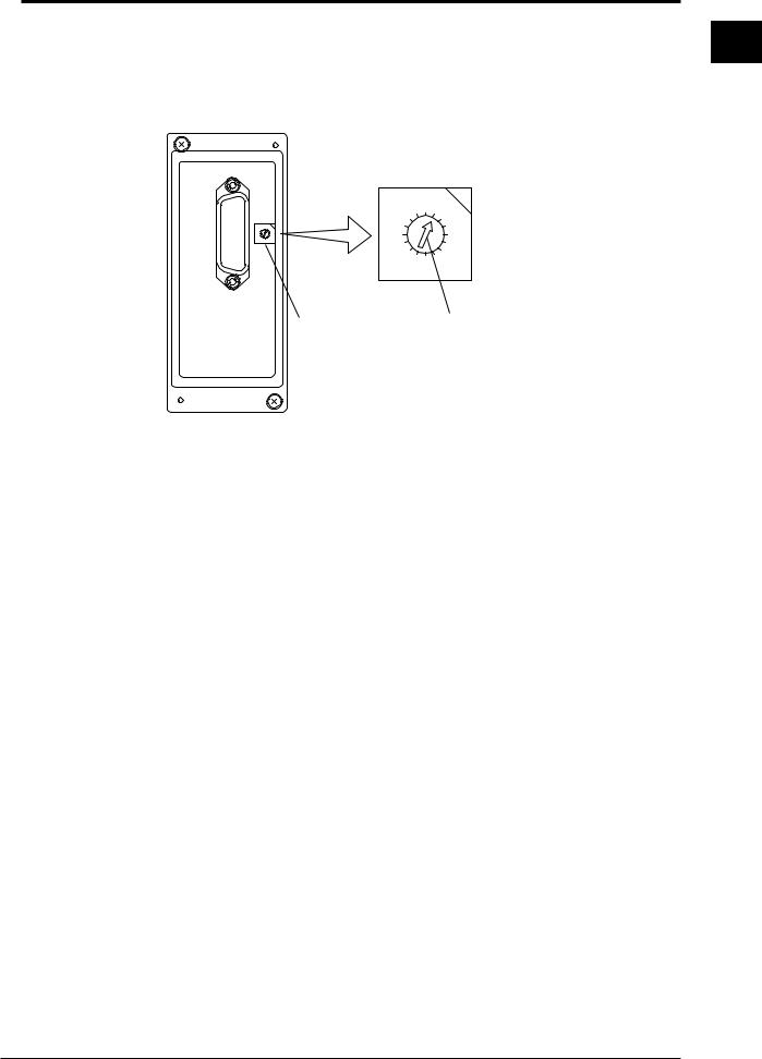
The GP-IB address is set with the rotary switch located on the side of the GP-IB module connector. Turn the arrow on the rotary switch with a flat-blade screwdriver or the like to align the arrow with the address to be set.
F0
CDE
B
A 98
12 |
|
3 |
|
4 |
|
76 |
5 |
|
F0 |
1 |
|
D |
E |
2 |
|
3 |
|||
|
4 |
||
C |
|||
B |
6 |
5 |
|
|
A |
|
|
|
98 |
7 |
|
|
|
|
|
Rotary switch with |
|
Address is the numeral |
|
which address is |
|
to which the arrow is pointed |
|
to be set |
|
|
|
1
Interface IB-GP of Specifications and Overview
IM DR231-11E |
1-3 |

 1.3 Specifications
Electrical and mechanical specifications: Conforming to IEEE St’d 488-1975
Code to be used: |
|
ISO (ASCII) code |
|
Function specifications |
|
|
|
|
|
|
|
Function |
Subset name |
Description |
|
Source handshake |
SH1 |
All transmission handshake functions operative |
|
Acceptor handshake |
AH1 |
All transmission handshake functions operative |
|
Talker |
T6 |
Basic talker functions, serial poll, and talker release function |
|
|
|
by listener are provided. |
|
Listener |
L4 |
Basic listener function and listener release function by talker |
|
|
|
are provided. |
|
Service request |
SR1 |
All service request functions operative |
|
Remote/local |
RL1 |
All remote/local functions operative |
|
Parallel poll |
PP0 |
No parallel poll function |
|
Device clear |
DC1 |
All device clear functions operative |
|
Device trigger |
DT1 |
All device trigger functions operative |
|
Controller |
C0 |
No controller function |
|
1-4 |
IM DR231-11E |
 2.1 Description of Functions (RS-232-C)
Listener and Talker Functions
Listener Function
This allows almost all settings except power on/off and operation control.
•Settings except communication settings.
•Operation control except power on/off.
•Call-up of setting data
•Specifying of output data (specifying of channel numbers or output data types)
Talker Function
The following data can be output:
•Measured data
•Data on RAM disk
•Report data
•Computed data
•System configuration
•Data for operation mode setting
•Data for setup mode setting
For measured data, data on RAM disk and computed data, either binary output or ASCII output can be selected. Report data are output in binary format. Other data are output in the form of ASCII data.
Data Output
When trigger(GET) becomes activated DR130/DR230/DR240 will store the new data in a buffer. When an output request such as the FM command is received, these new data will be output.
2
Interface C-232-RS of Specifications and Overview
IM DR231-11E |
2-1 |

2.1 Description of Functions
Commands Applicable to RS-232-C Only
The following commands are only applicable to RS-232-C.
ESC T Trigger Execution
Setting |
ESC T<terminator> |
Description |
Before executing this command, select the output data using the TS command. The |
|
data selected with the TS command are prepared for output. The data are output |
|
with the FM, LF, CF, MF or RF command. |
ESC S Status Output Command |
|
Setting |
ESC S<terminator> |
Description |
The status for a sent command is output. |
ESC R Switch from Local Status to Remote Status |
|
Setting |
ESC R<terminator> |
Description |
• Panel setting conditions in the local status are retained even if the status is switched |
|
to the remote status. |
|
• When the status is switched to the remote status, no key except DISP can be used. |
|
Panel operation can be done by pressing the DISP key or switching the status to |
|
local using the ESC L command described below. |
ESC L Switch from Remote Status to Local Status
Setting |
ESC L<terminator> |
Description |
The panel setting conditions in the remote status are retained even if the status is |
|
switched to the local status. |
Note
• ESC corresponds to hexadecimal code (1B)H.
Status Byte Format
When the status byte output command (ESC S) is received, any of the ER00CRLF to ER03CRLF status will be output.
ER 


 CrLf
CrLf
 An ASCII character string of a numeral (numerals) shown inparentheses at the end of any of the following items or the sum of the numerals of the relevant items is output.
For example, if out-of-chart and timer operation occur, ER20CrLf is output.
Items not specified with an IM command are invalid and not included in this status output.
•A/D conversion end (1)
When an A/D conversion for measured data ends, “1” is output.
•Syntax error (2)
If an error occurs in the description of a command, “2” is output.
•Internal timer or time when hourly, daily and monthly reports are created(4)
If any of the 6 timers (1 to 6) or the time for hourly, daily and monthly reports arrives set with an auxiliary mask operates, “4” is output.
•Storing data or reading data end (8)
When storing data on media, or reading data from media ends, “8” is output.
•Out-of-chart (16)
If out-of-chart is detected, “16” is output.
•Measurement release (32)
If a measurement release is generated while the computation is in progress, “32” is output.
Items Applicable to RS-232-C Only
With RS-232-C, all commands can be acknowledged by ACK output. The ACK output is as follows, except for the FM, LF, CF, RF and BL commands, whose ACK output will described later on.
E0 : Commands are processed succesfully
E1 : Commands are not processed succesfully
After having sent the output request, make sure to retrieve the data.
2-2 |
IM DR231-11E |

|
|
2.2 |
Specifications |
|
|
|
|
Electrical & mechanical specs |
: Conform to the EIA RS-232-C Standard. |
|
|
|
||
|
|
|
Connection format |
: Point-to point |
|
|
|
Communication format |
: Half duplex |
|
|
|
Synchronizing format |
: Start-stop asynchronous transmission |
|
|
|
|
(synchronized by start/stop bit) |
|
|
|
Baud rate (bps) |
: 150, 300, 600, 1200, 2400, 4800, 9600, 19200, 38400 |
|
|
|
START bit |
: 1 bit, fixed. |
|
|
|
Data length |
: Either 7 or 8 bits (selectable). |
|
|
|
Parity |
: Even, Odd, or None (selectable). |
|
|
|
STOP bit |
: Either 1 or 2 bits (selectable). |
|
|
|
Connector |
: DBSP-JB25S (JAE) |
|
|
|
Hardware handshake |
: Transmission/reception control by DTR, RTS, CTS. |
|
|
|
Software handshake |
: Transmission control by XON, XOFF. |
|
|
|
Reception buffer length |
: 200 bytes |
|
|
|
Escape sequence |
: Trigger; |
|
|
|
|
Status call. |
2
Interface C-232-RS of Specifications and Overview
IM DR231-11E |
2-3 |
 2.3 RS-232-C Interface Connection
When connecting this instrument to a personal computer, first it is necessary to match settings such as handshake format, data transmission speed, and data format at the computer’s side. For details relating to these settings, refer to the description on this and following pages. Furthermore, make sure to use an interface cable which matches this instrument’s specifications.
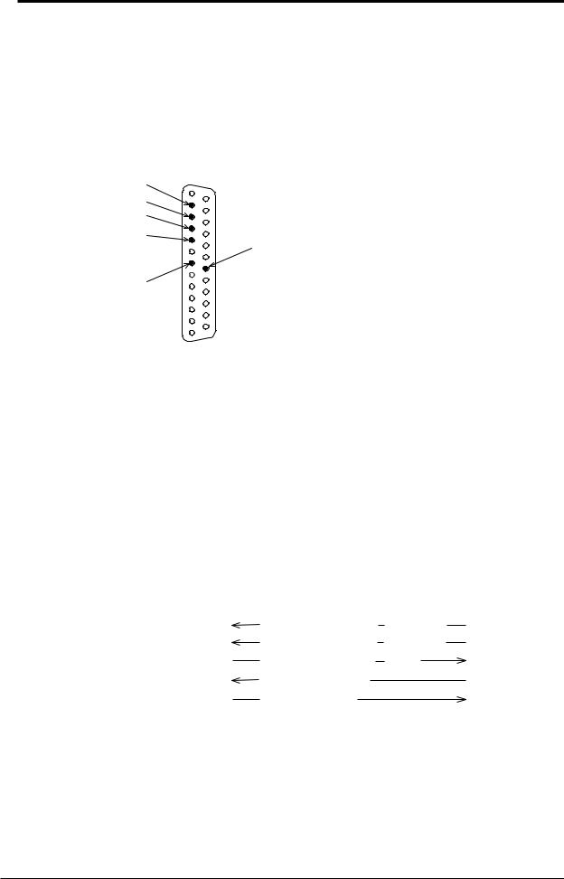
Connector and Signal Names
2
3
4
5
20 |
|
7 |
|
Numeric values in the above figure indicate Pin Nos. |
|
2.TXD (Send Data) |
: Data transmitted to the host computer. |
|
Signal direction : Output. |
3.RXD (Received Data) |
: Data received from the host computer. |
|
Signal direction : Input. |
4.RTS (Request to Send) |
: Handshake signal used for reception of data from the host computer. |
|
Signal direction : Output. |
5.CTS (Clear to Send) |
: Handshake signal used for transmission of data to the host |
|
computer. |
|
Signal direction : Input. |
7.GND (Signal Ground) |
: Signal ground connection. |
20.DTR (Equipment Ready) : Handshake signal used for reception of data from the host computer.
Signal direction : Output. Pin Nos. 1, 6 and 8 to 19 are not used.
Signal direction
|
DTR [Transmission request |
reception OK] |
20 |
|
|
RTS [Transmission request |
reception OK] |
4 |
|
Host Computer |
CTS [Transmission enable |
Ready] |
5 |
DR series |
|
TXD [Transmission data] |
|
2 |
|
|
RXD [Reception data] |
|
3 |
|
|
|
|
|
|
2-4 |
IM DR231-11E |

|
|
|
|
|
|
2.3 RS-232-C Interface Connection |
|
||
RS-232-C Signal List and Corresponding JIS & CCITT Abbreviation |
|
|
|||||||
|
|
|
|
Signal Table |
|
|
|
|
|
|
|
|
|
|
|
|
|
|
|
|
Pin No. |
|
Abbreviation |
|
Name |
|
|
|
|
|
|
|
|
|
|
|
|
||
|
RS-232-C |
|
CCITT |
JIS |
|
|
2 |
||
|
|
|
|
|
|
||||
|
|
|
|
|
|
|
|
|
|
|
7 |
AB(GND) |
|
102 |
SG |
Signal ground |
|
|
|
|
|
|
|
|
|||||
|
|
|
|
|
|
|
|
|
|
|
2 |
BA(TXD) |
|
103 |
SD |
Transmitted data |
|
|
Overview |
|
3 |
BB(RXD) |
|
104 |
RD |
Received data |
|
|
|
|
|
|
|
|
|||||
|
5 |
CB(CTS) |
|
106 |
CS |
Transmission enable |
|
|
|
|
4 |
CA(RTS) |
|
105 |
RS |
Transmission request |
|
|
and |
|
|
|
|
|
|||||
|
|
|
|
|
|
|
|
|
|
|
20 |
CD(DTR) |
|
108/2 |
ER |
Data terminal ready |
|
|
InterfaceC-232-RSofSpecifications |
|
|
|
|
|
|
|
|
|
|
|
|
|
|
|
|
|
|
|
|
IM DR231-11E |
2-5 |
 2.4 Handshake Format Selection
In order to ensure proper data transfers between the recorder and the host computer via the RS-232- C interface, a mutual procedure is required for processing the electrical signals. Such a procedure is referred to as a ‘handshake’. Several handshake formats are available, with selection depending on the host computer being used. The same handshake format must be designated for both the recorder and the host computer.
The recorder parameter settings permit any one of the following 5 formats to be selected.
|
|
Transmission Data Control |
Reception Data Control |
|
||||||
|
|
(Control format when transmitting data |
(control format when receiving data |
|||||||
|
|
to the host computer) |
|
from the host computer) |
||||||
Format |
Software |
Hardware |
|
|
Hardware |
|
|
|||
Handshake |
Handshake |
|
|
Handshake |
|
|
||||
Selection |
|
|
|
|
||||||
|
|
Transmission is |
Transmission |
|
No |
When reception |
When reception |
|
No |
|
|
|
stopped when |
is stopped |
|
Handshake |
of data becomes |
of data becomes |
|
Handshake |
|
|
|
X-OFF is |
when CTS is |
|
|
impossible DTR |
impossible RTS |
|
|
|
|
|
received, and is |
FALSE, and is |
|
|
becomes |
becomes |
|
|
|
|
|
resumed when |
resumed when |
|
|
FALSE, when |
FALSE, when |
|
|
|
|
|
X-ON is |
CTS is TRUE. |
|
|
data recept |
data recept |
|
|
|
|
|
received. |
|
|
|
|
becomes |
becomes |
|
|
|
|
|
|
|
|
|
possible DTR |
possible RTS |
|
|
|
|
|
|
|
|
|
becomes TRUE. |
becomes TRUE. |
|
|
O F F - O F F |
|
|
|
|
|
|
|
|
|
|
|
|
|
|
|
|
|
|
|
|
|
X O N - R T S |
|
|
|
|
|
|
|
|
|
|
|
|
|
|
|
|
|
|
|
|
|
X O N - D T R |
|
|
|
|
|
|
|
|
|
|
|
|
|
|
|
|
|
|
|
|
|
C T S - R T S |
|
|
|
|
|
|
|
|
|
|
|
|
|
|
|
|
|
|
|
|
|
C T S - D T R |
|
|
|
|
|
|
|
|
|
|
|
|
|
|
|
|
|
|
|
|
|
OFF-OFF |
|
|
|
|
|
|
|
|
|
|
• |
Transmission data control |
: There is no handshake status between the recorder and host |
||||||||
|
|
|
|
computer. the X-OFF signal from the host computer is processed |
||||||
|
|
|
|
as data, and the CTS signal is ignored. |
|
|||||
• |
Reception data control |
: There is no handshake status between the recorder and host |
||||||||
|
|
|
|
computer. When the recorder reception buffer becomes full, the |
||||||
|
|
|
|
excess data is discarded. |
|
|
|
|||
|
|
|
|
DTR=True, RTS=True (both fixed). |
|
|||||
Note
•It is necessary to create a host computer program which prevents the recorder and host computer reception buffers from becoming full.
XON-RTS |
|
|
• |
Transmission data control |
: A software handshake status is established between the recorder |
|
|
and the host computer. The recorder will stop a data transmission |
|
|
when an X-OFF signal is received from the host computer. The |
|
|
transmission will be resumed when the next X-ON signal is |
|
|
received. |
|
|
The CTS signal from the host computer is ignored. |
• |
Reception data control |
: A hardware handshake status is established between the recorder |
|
|
and the host computer. When the recorder recept of data becomes |
|
|
impossible, an ‘RTS=False’ status will be established. When data |
|
|
recept becomes possible, an ‘RTS=True’ status will be established. |
|
|
DTR=True (Fixed). |
2-6 |
IM DR231-11E |

|
|
2.4 Handshake Format Selection |
XON-DTR |
|
|
• |
Transmission data control |
: A software handshake status is established between the recorder |
|
|
and the host computer. The recorder will stop a data transmission |
|
|
when an X-OFF signal is received from the host computer. The |
|
|
data transmission will be resumed when the next X-ON signal is |
|
|
received. The CTS signal from the host computer is ignored. |
• |
Reception data control |
: A hardware handshake status is established between the recorder |
|
|
and the host computer. When the recorder recept of data becomes |
|
|
impossible, an ‘DTR=False’ status will be established. When data |
|
|
recept become possible, an ‘DTR=True’ status will be established. |
|
|
RTS=True (Fixed). |
CTS-RTS |
|
|
• |
Transmission data control |
: A hardware handshake status is established between the recorder |
|
|
and the host computer. The recorder will stop a data transmission |
|
|
if a ‘CTS=False’ status is established, and will resume the |
|
|
transmission when a ‘CTS=True’ status is established. The X- |
|
|
OFF and X-ON signals from the host computer are processed as |
|
|
data. |
• |
Reception data control |
: A hardware handshake status is established between the recorder |
|
|
and the host computer. An ‘RTS=False’ status will be established |
|
|
when the recorder recept of data becomes impossible, and an |
|
|
‘RTS=Ture’ status will be established when data recept becomes |
|
|
possible. DTR=Ture (Fixed). |
CTS-DTR |
|
|
• |
Transmission data control |
: A hardware handshake status is established between the recorder |
|
|
and the host computer. The recorder will stop a data transmission |
|
|
if a ‘CTS=False’ status is established, and will resume the |
|
|
transmission when a ‘CTS=True’ status is established. The X- |
|
|
OFF and X-ON signals from the host computer are processed as |
|
|
data. |
• |
Reception data control |
: A hardware handshake status is established between the recorder |
|
|
and the host computer. A ‘DTR=False’ status will be established |
|
|
when the recorder recept of data becomes impossible and a |
|
|
‘DTR=True’ status will be established when data recept becomes |
|
|
possible. RTS=Ture (Fixed). |
2
Interface C-232-RS of Specifications and Overview
IM DR231-11E |
2-7 |

 2.5 Communication Data Format
The RS-232-C interface uses a START-STOP communication format. With this format, a START bit is placed at the beginning of each character transmitted, followed by the data bits, parity bit, and stop bit, in that order. (See the figure below.)
Return to ‘line idle’ condition (dotted line), or proceed to
‘Line idle’  1 character
  next data START bit.
condition
Data bits
(7-8 bits)
|
|
|
|
|
|
STOP bit |
|
|
||
|
|
|
|
|
|
|
|
|
|
|
|
|
|
|
Parity bit(Odd, |
|
1 |
|
|
|
|
|
|
|
|
|
|
|
|
|||
|
|
|
|
|
|
|
|
|
|
|
START bit |
even, or none) |
|
1 or 2 |
|
|
|||||
|
|
|
|
|
|
2 |
|
|
||
|
|
|
|
|
|
|
|
|
|
|
2-8 |
IM DR231-11E |
 2.6 RS-232-C Interface Parameter Setting Procedure
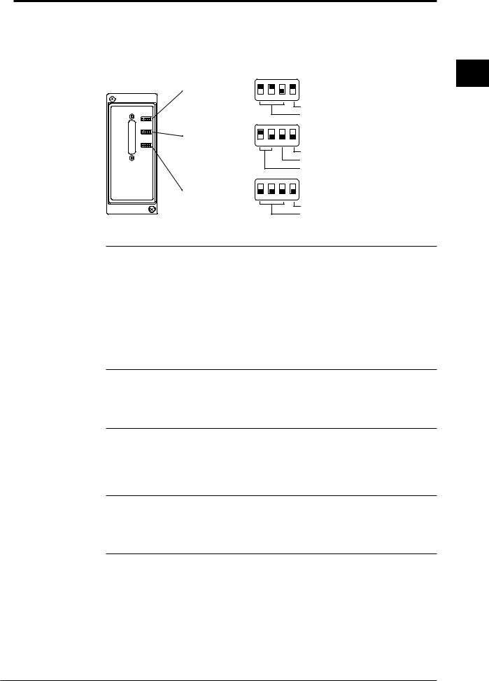
Setting of the RS-232-C parameters must be carried out using the 3 dipswitches located next to the module connector.
Parameter setting |
|
|
|
ON |
|
1 |
2 |
3 |
4 OFF |
||
switch 1 |
|||||
|
|
|
Data length |
||
|
|
|
|
||
|
|
|
|
Baud rate |
|
Parameter setting |
|
|
|
ON |
|
1 |
2 |
3 |
4 OFF |
||
switch 2 |
|||||
|
|
|
Baud rate |
||
|
|
|
|
||
|
|
|
|
Stop bit |
|
|
|
|
|
Parity |
|
Parameter setting |
|
|
|
ON |
|
1 |
2 |
3 |
4 OFF |
||
switch 3 |
|||||
|
|
|
Not use |
||
|
|
|
|
||
|
|
|
|
Handshake system |
Baud rate (No.1 to 3 of setting switch 1 and No.4 of setting switch 2)
Baud rate |
No.1 |
No.2 |
No.3 |
No.4 (switch 2) |
|
150 |
OFF |
OFF |
OFF |
OFF |
|
300 |
OFF |
OFF |
ON |
OFF |
|
600 |
OFF |
ON |
OFF |
OFF |
|
1200 |
OFF |
ON |
ON |
OFF |
|
2400 |
ON |
OFF |
OFF |
OFF |
|
4800 |
ON |
OFF |
ON |
OFF |
|
9600 |
ON |
ON |
OFF |
OFF |
← Default |
19200 |
ON |
ON |
ON |
OFF |
|
38400 |
OFF |
OFF |
OFF |
ON |
|
Data length (Switch No.4 of parameter setting switch 1)
Data length |
No.4 |
|
7 |
OFF |
|
8 |
ON |
← Default |
Parity (Switch No.1 and 2 of parameter setting switch 2)
Parity |
No.1 |
No.2 |
|
NONE |
OFF |
OFF |
|
ODD |
OFF |
ON |
|
EVEN |
ON |
OFF |
← Default |
Stop bit (Switch No.3 of parameter setting switch 2)
Stop bit |
No.4 |
|
1 |
OFF |
← Default |
2 |
ON |
|
Handshake system (Switch No.1 to 3 of parameter setting switch 3)
Handshake system |
No.1 |
No.2 |
No.3 |
No handshake |
OFF |
OFF |
OFF ← Default |
XON-ER* |
OFF |
OFF |
ON |
XON-RS* |
OFF |
ON |
OFF |
CS-ER |
OFF |
ON |
ON |
CS-RS |
ON |
OFF |
OFF |
* When the baud rate is set to 38400, there is no handshaking.
2
Interface C-232-RS of Specifications and Overview
IM DR231-11E |
2-9 |


 3.1 Description of Functions (RS-422-A/RS-485)
Listener and Talker Functions
Listener Function
This allows almost all settings except power on/off and operation control.
•Settings except communication settings.
•Operation control except power on/off.
•Call-up of setting data
•Specifying of output data (specifying of channel numbers or output data types)
Talker Function
The following data can be output:
•Measured data
•Data on RAM disk
•Report data
•System configuration
•Data for operation mode setting
•Data for setup mode setting
For measured data and data on RAM disk, binary output or ASCII output can be selected. (for RS- 422-A with using the multi point.) Report data are output in binary format. Other data are output in the form of ASCII data.
Data Output
When trigger(ESC T) becomes activated DR will store the new data in a buffer. When an output request such as the FM command is received, these new data will be output.
Commands Applicable to RS-422-A/RS-485 Only
The following commands are only applicable to RS-422-A/RS-485.
ESC O Open Command (address a communication destination)
Setting |
ESC O xx<terminator> |
|
xx : address, 01 to 31 |
Description |
Specifies the communicating device by its address. When this command is ex- |
|
ecuted, all commands to the DR series (including ESC T) become effective. |
|
• Only one device can be opened. |
|
• Executing ESC O automatically closes all opened devices. |
|
• When the DR series receives this command correctly, it sends “ESC O xx” in |
|
response to the computer. |
|
• CR+LF can only used for the terminator. |
ESC C Close Command (close the addressed state of a device)
Setting |
ESC C xx<terminator> |
|
xx : address, 01 to 31 |
Description |
Disconnects the device currently connected. When this command is executed, it |
|
allows opening communication with other devices with the ESC O command. |
|
• When the DR series receives this command correctly, it sends “ESC C xx” in |
|
response to the computer. |
|
• CR+LF can only used for the terminator. |
The following commands are same as the RS-232-C interface. Refer to User’s Manual shown below.
ESC T (Trigger Execution), ESC S (Status Output Command)
Note
• ESC corresponds to hexadecimal code (1B)H. On the N88-BASIC, “ESC x” is denoted as “CHR$(&H1B)+”x”.”
3
Interface 485-A/RS-422-RS of Specifications and Overview
IM DR231-11E |
3-1 |
|
|
3.2 |
Specifications |
|
|
|
|
|
Electrical & mechanical specs |
: Conform to the EIA RS-422-A and EIA RS-485 Standard |
|
|
|
|
|||
|
|
|
Connection format |
: Multi-drop 1:n (n=16 for RS-422-A, n=31 for RS-485) |
|
|
|
|
Communication format |
: Half duplex |
|
|
|
|
Synchronizing format |
: Start-stop asynchronous transmission (synchronized by start/stop |
|
|
|
|
|
|
bit) |
|
|
|
Baud rate (bps) |
: 300, 600, 1200, 2400, 4800, 9600, 19200, or 38400 (selectable) |
|
|
|
|
START bit |
: |
1 bit (fixed) |
|
|
|
Data length |
: |
Either 7 or 8 bits (selectable) |
|
|
|
Parity |
: |
Even, Odd, or None (selectable) |
|
|
|
STOP bit |
: |
Either 1 or 2 bits (selectable) |
|
|
|
Connector |
: |
6 point screw type terminal (uses M4 screws) |
|
|
|
Minimum response time |
: |
0, 10, 20, 50, or 100 ms (selectable) |
|
|
|
Reception buffer length |
: |
250 bytes |
|
|
|
Escape sequence |
: Trigger, Status call, Open and Close |
|
|
|
|
Electrical characteristics |
: SDA, SDB, RDA, RDB, SG. Between the signal terminal and |
|
|
|
|
|
|
the main internal circuit is insulated functionally. |
|
|
|
Communication distance |
: 1.2 km maximum |
|
|
|
|
Terminator |
: Internal resistor (120 ohm, 1W) switch with the slide switch |
|
3-2 |
IM DR231-11E |

 3.3 RS-422-A/RS-485 Interface Connection
The following explains how the RS-422-A/RS-485 module is connected to the computer.
Cable Used
There are two types of cables: two-wire cable and four-wire cable. Make sure each type meets the
following conditions. |
|
|
Cable used |
: twisted pair shielded cable |
|
|
|
2 pairs of 24 AWG minimum (two-wire), 3 pairs 24 AWG mini- |
|
|
mum (four-wire) |
Characteristic impedance |
: |
100 ohm |
Capacitance |
: |
50 pF/m |
Length of cable |
: 1.2 km maximum * |
|
*Communication distance of the RS-422-A/RS-485 interface is not the linear distance, but the total length of the cable (shielded twisted pair cable).
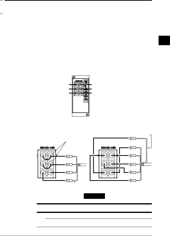
Terminal Arrangement of the RS-422-A/RS-485 Module
RD A Receive data A ( - ) |
SD A Send data A ( - ) |
RD B Receive data B ( + ) |
SD B Send data B ( + ) |
FG Frame ground |
SG Signal ground |
Screws used for the terminals:
ISO M4 screws, length 6 mm
Connecting the Cable
Attach crimp-on lugs (for 4 mm screws) with insulation sleeves on the leadwire ends as shown in the diagram below. Make the exposed portion of the shielded cable to be less than 5 cm.
Short the terminals.
SD/RD A
SD/RD B
SG
FG
Shield
FG potential
SG
SD A
SD B |
RD B |
RD A |
 Shield potential
For two-wire system |
For four-wire system |
WARNING
To prevent an electric shock, ensure the main power supply is turned OFF.
Note
•As shown on the next page, connect terminal RD to SD(TD) of the computer (converter) and terminal SD to RD of the computer.
3
Interface 485-A/RS-422-RS of Specifications and Overview
IM DR231-11E |
3-3 |

3.3 RS-422-A/RS-485 Interface Connection
Connecting to the Host Computer
Can be connected to a host computer with RS-232-C, RS-422-A, RS-485 ports.
•In the case of RS-232-C, a converter is used as shown in the diagram below.
•For information on recommended converters, refer to “Converters” in the latter.
•Dip switch needs to be changed depending on whether it is a two-wire system or four-wire system. Refer to “3.5 RS-422-A/RS-485 Interface Parameter Setting Procedure.”
Host
Computer
SDA( - ) |
SDB( + ) |
RDA( - ) |
RDB( + ) |
SG |
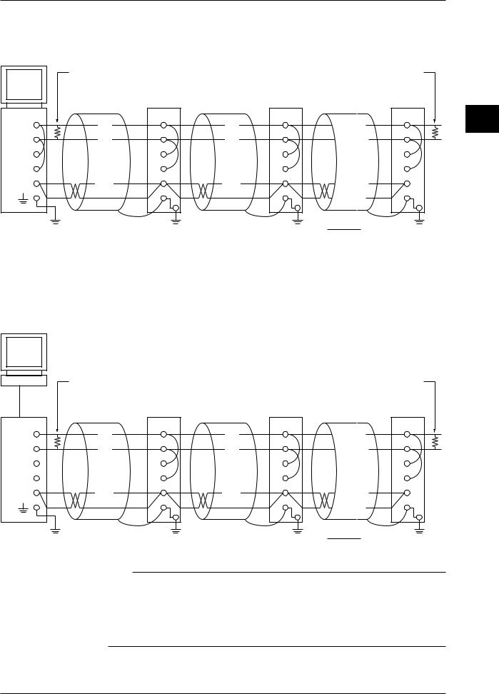
In the case of four-wire system
In general, the recorder is wired to the host computer using a four-wire system. When four-wire system is used, the send and receive wires need to be crossed.
Terminator (externally applied) 120 ohm, more than 1/2 W
RS-422-A/RS-485 module
of the DA100/DR
|
SD A |
(SDA) |
(SDA) |
|
SD B |
(SDB) |
(SDB) |
|
RD A |
(RD A) |
(RD A) |
|
RD B |
(RD B) |
(RD B) |
|
SG |
(SG) |
(SG) |
FG
#1
SD A |
SD B |
RD A |
RD B |
SG |
FG |
#2 |
Terminator (Internal ON)
SD A
(SDA)
SD B
(SDB)
RD A
(RD A)
RD B
(RD B)
SG
(SG)
FG
#n
(#n≤ 31)
No terminators are inserted between #1 through #n-1 (internal OFF)
(Diagram below shows the case when the port of the host computer is RS-232-C)
Host
Computer
Terminator (externally applied) 120 ohm, more than 1/2 W |
Terminator (Internal ON) |
RS-232-C |
RS-422-A/RS-485 |
|
|
module |
|
|
|
|
of the DA100/DR |
|
|
TD( - ) |
SD A |
SD A |
SD A |
(SDA) |
(SDA) |
(SDA) |
|
TD( + ) |
SD B |
SD B |
SD B |
(SDB) |
(SDB) |
(SDB) |
|
RD( - ) |
RD A |
RD A |
RD A |
(RD A) |
(RD A) |
(RD A) |
|
RD( + ) |
RD B |
RD B |
RD B |
(RD B) |
(RD B) |
(RD B) |
|
SHIELD |
SG |
SG |
SG |
(SG) |
(SG) |
(SG) |
|
|
FG |
FG |
FG |
Converter |
#1 |
#2 |
#n |
|
|
(#n≤ 31) |
|
Z - 101HE |
|
|
|
(SHARP) |
No terminators are inserted between #1 through #n-1 (internal OFF) |
||
|
|||
3-4 |
IM DR231-11E |
3.3 RS-422-A/RS-485 Interface Connection
In the case of two-wire system
Connect send and receive terminals with the same signal polarity on the terminal arrangement of the RS-422-A/RS-485 module. Only two wires are used in connecting to other units.
Host
Computer
Terminator (externally applied) 120 ohm, more than 1/2 W |
Terminator (Internal ON) |
RS-422-A/RS-485 module
of the DA100/DR
SDA( - ) |
SD A |
(A) |
|
SDB( + ) |
SD B |
(B) |
|
RDA( - ) |
RD A |
|
|
RDB( + ) |
RD B |
|
|
SG |
SG |
(SG) |
|
|
FG |
#1
SD A |
SD A |
(A) |
(A) |
SD B |
SD B |
(B) |
(B) |
RD A |
RD A |
RD B |
RD B |
SG |
SG |
(SG) |
(SG) |
FG |
FG |
#2 |
#n |
|
(#n≤ 31) |
No terminators are inserted between #1 through #n-1 (internal OFF)
(Diagram below shows the case when the port of the host computer is RS-232-C)
Host
Computer
|
Terminator (externally applied) 120 ohm, more than 1/2 W |
Terminator (Internal ON) |
|
RS-232-C |
RS-422-A/RS-485 |
|
|
module |
|
|
|
|
|
|
|
|
of the DA100/DR |
|
|
TD( - ) |
SD A |
SD A |
SD A |
(A) |
(A) |
(A) |
|
TD( + ) |
SD B |
SD B |
SD B |
(B) |
(B) |
(B) |
|
RD( - ) |
RD A |
RD A |
RD A |
|
|
|
|
RD( + ) |
RD B |
RD B |
RD B |
|
|
|
|
SHIELD |
SG |
SG |
SG |
(SG) |
(SG) |
(SG) |
|
|
FG |
FG |
FG |
Converter |
#1 |
#2 |
#n |
|
|
(#n≤ 31) |
|
Z - 101HE |
|
|
|
(SHARP) |
No terminators are inserted between #1 through #n-1 (internal OFF) |
||
|
|||
Note
•The method in eliminating noise depends on the condition in which it is used. In the example, shielded cable is grounded only at the DR (one-sided grounding). This method is effective in eliminating noise in long distance communication in which there is potential difference between the ground of the PC and the ground of the DR. When there is no potential difference between the ground of the PC and the ground of the DR, grounding both sides (two-sided grounding) is sometimes effective. In addition, there are cases when grounding both sides with one side having a capacitor connected in series is effective.
Consider all the above cases in eliminating the noise.
3
Interface 485-A/RS-422-RS of Specifications and Overview
IM DR231-11E |
3-5 |

3.3 RS-422-A/RS-485 Interface Connection
Converter
Recommended converter : Sharp Z-101HE
Caution
Some converters other than the recommended, do not have the FG and SG terminals insulated. In such cases, do not connect as in the diagram on the previous page (do not connect anything to the FG and SG terminals of the converter). Especially when it is long distance, the potential difference may damage the devices or the communication may become unreliable.
Also, converters without the SG terminal can be used without grounding. For details, refer to the converter’s manual.
Some converters other than the recommended have their signal polarity reversed (indication of A/B or +/-). In this case, reverse the connection. If the “RD” LED on the front panel of the RS-422-A/ RS-485 module blinks when it receives data, the connection is correct. If it lights, the connection may be reversed.
In the case of the two-wire system, the host computer must control the ON/OFF of the transmission driver of the converter in order to prevent the collision of the send and receive data. When using the recommended converter, ON/OFF is controlled using RTS.
Using the Module with Devices Using the RS-422-A
Maximum of 31 devices with respect to 1 host computer can be connected with this module, but in a system in which devices using the RS-422-A are used together, this may not be possible.
•In a system in which former Yokogawa recorders are used together
Some of the former Yokogawa recorders (such as HR2400 and R) use the RS-422-A driver. In this case, the maximum number of devices that can be connected is 16.
Note
•According to the RS-422-A standard, the maximum number of devices that can be connected with respect to one port is 10 devices (in the case of a four-wire system).
Terminator
When devices are connected in multi-drop configuration (includes point-to-point connections), turn the terminators of the modules on the extreme ends ON. All modules in between should have them turned off. Terminators are turned ON/OFF using the TERMIN switch on the front panel.
Also, turn ON the terminator on the host computer (refer to the computer’s manual). When converters are used, turn their terminators ON also. The recommended converter needs an external terminator to be installed, but some converters are internal types.
3-6 |
IM DR231-11E |
3.3 RS-422-A/RS-485 Interface Connection
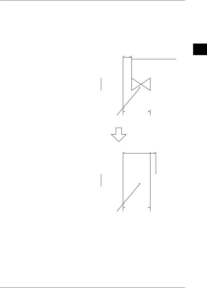
Minimum Response Time
Because send and receive are done on the same line in the two-wire system, minimum response time needs to be set. The minimum response time is the amount of time the RS-422-A/RS-485 module waits in order for the host computer to be able to receive the data after it sends data. The time can be set in the range from 0 to 100 ms. Set the time using the dip switch on the front panel of the RS-422- A/RS-485 module to match the computer or the converter’s specification. (Refer to “3.5 RS-422-A/ RS-485 Interface Parameter Setting Procedure.”) Note that the minimum response time is, as the name indicates, the minimum time for responding. Not all responses will take place in this time.
In the four-wire system, the minimum response time does not need to be set (set to 0 ms).
Response from the computer is too early
Active
DA100/DR side
Transmission driver |
|
|
|
|
|
|
||
|
|
|
|
|
|
|
|
|
|
|
|
|
|
|
|
|
|
Data |
PC -> DA100/DR Terminator |
|
|
|
|
DA100/DR -> PC |
||
|
|
|
|
|
|
|
|
|
|
|
|
|
|
|
|
|
|
Computer side |
Active |
|
|
|
|
|
|
|
Transmission driver |
|
|
|
|
|
|
||
|
|
|
|
|
|
|
|
|
|
|
|
|
|
|
|
|
|
|
|
|
|
|
|
|
|
|
|
Driver simultaneously becomes |
Delay after sending the terminator |
||||||
|
output mode, and the data collides. |
|||||||
|
|
|
|
|
|
|
||
Insert appropriate time for waiting
DA100/DR side |
|
|
|
|
|
|
Active |
|
|
|
|
|
|
|
|
||
Transmission driver |
|
|
|
|
|
|
||
Data |
|
|
|
|
|
|
|
|
|
|
|
|
|
|
|||
PC -> DA100/DR Terminator |
|
|
|
DA100/DR -> PC |
||||
|
|
|
|
|
|
|
|
|
|
|
|
|
|
|
|
|
|
Computer side |
Active |
|
|
|
|
|
|
|
Transmission driver |
|
|
|
|
|
|
||
|
|
|
|
|
|
|
|
|
|
|
|
|
|
|
|
|
|
|
|
|
|
|
|
|
|
|
|
No time interval in which there is |
Delay after sending the terminator |
||||||
|
data collision. |
|||||||
|
|
|
|
|
|
|
||
3
Interface 485-A/RS-422-RS of Specifications and Overview
IM DR231-11E |
3-7 |


 3.4 Communication Data Format
Same as the RS-232-C interface. For a description, refer to “2.5 Communication Data Format.”
3-8 |
IM DR231-11E |
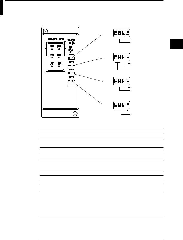
3.5RS-422-A/RS-485 Interface Parameter Setting
Procedure
Setting of the RS-422-A/RS-485 parameters must be carried out using the 4 dip switches located next to the module connector.
|
|
|
SW1 |
|
|
ON |
|
|
|
2 |
3 |
4 OFF |
|
|
|
|
1 |
|||
|
|
|
|
|
|
Data length |
|
|
|
|
|
|
Baud rate |
|
|
|
SW2 |
|
|
ON |
|
|
|
2 |
3 |
4 OFF |
|
|
|
|
1 |
|||
|
|
|
|
|
|
four-wire/two-wire |
|
|
|
|
|
|
Stop bit |
|
|
|
|
|
|
Parity |
|
|
|
SW3 |
|
|
ON |
|
|
|
2 |
3 |
4 OFF |
|
|
|
|
1 |
|||
|
|
|
|
|
|
Address (upper) |
|
|
|
|
|
|
Minimum response time |
|
|
|
SW4 |
|
|
ON |
|
|
|
2 |
3 |
4 OFF |
|
|
|
|
1 |
|||
|
|
|
|
|
|
Address (lower) |
Baud rate (No.1 to 3 of SW1) |
|
|
|
|
|
|
Baud rate |
No.1 |
No.2 |
No.3 |
|
|
|
300 |
OFF |
OFF |
ON |
|
|
|
600 |
OFF |
ON |
OFF |
|
|
|
1200 |
OFF |
ON |
ON |
|
|
|
2400 |
ON |
OFF |
OFF |
|
|
|
4800 |
ON |
OFF |
ON |
|
|
|
9600 |
ON |
ON |
OFF ← Default Setting |
|
|
|
19200 |
ON |
ON |
ON |
|
|
|
38400 |
OFF |
OFF |
OFF |
|
|
|
Data length (No.4 of SW1) |
|
|
|
|
|
|
Data length |
No.4 |
|
|
|
|
|
7 |
OFF |
|
|
|
|
|
8 |
ON |
← Default Setting |
|
|
|
|
Parity (No.1 to 2 of SW2)
Parity |
No.1 |
No.2 |
None |
OFF |
OFF |
ODD |
OFF |
ON |
EVEN |
ON |
OFF ← Default Setting |
Stop bit (No.3 of SW2)
Stop bit |
No.3 |
1 |
OFF ← Default Setting |
2 |
ON |
Switch between four-wire/two-wire systems (No.4 of SW2)
|
four-wire/two-wire |
No.4 |
|
|
four-wire |
OFF |
← Default Setting |
|
two-wire |
ON |
|
|
|
|
|
3
Interface 485-A/RS-422-RS of Specifications and Overview
IM DR231-11E |
3-9 |

3.5 RS-422-A/RS-485 Interface Parameter Setting Procedure
Minimum response time (No.1 to 3 of SW3)
Minimum response time |
No.1 |
No.2 |
No.3 |
0ms |
OFF |
OFF |
OFF ← Default Setting |
10ms |
OFF |
OFF |
ON |
20ms |
OFF |
ON |
OFF |
50ms |
OFF |
ON |
ON |
100ms |
ON |
OFF |
OFF |
Address (No.4 of SW3 and No.1 to 4 of SW4)
Address |
No.4(SW3) |
No.1(SW4) |
No.2(SW4) |
No.3(SW4) |
No.4(SW4) |
1 |
OFF |
OFF |
OFF |
OFF |
ON ← Default Setting |
2 |
OFF |
OFF |
OFF |
ON |
OFF |
3 |
OFF |
OFF |
OFF |
ON |
ON |
4 |
OFF |
OFF |
ON |
OFF |
OFF |
5 |
OFF |
OFF |
ON |
OFF |
ON |
6 |
OFF |
OFF |
ON |
ON |
OFF |
7 |
OFF |
OFF |
ON |
ON |
ON |
8 |
OFF |
ON |
OFF |
OFF |
OFF |
9 |
OFF |
ON |
OFF |
OFF |
ON |
10 |
OFF |
ON |
OFF |
ON |
OFF |
11 |
OFF |
ON |
OFF |
ON |
ON |
12 |
OFF |
ON |
ON |
OFF |
OFF |
13 |
OFF |
ON |
ON |
OFF |
ON |
14 |
OFF |
ON |
ON |
ON |
OFF |
15 |
OFF |
ON |
ON |
ON |
ON |
16 |
ON |
OFF |
OFF |
OFF |
OFF |
17 |
ON |
OFF |
OFF |
OFF |
ON |
18 |
ON |
OFF |
OFF |
ON |
OFF |
19 |
ON |
OFF |
OFF |
ON |
ON |
20 |
ON |
OFF |
ON |
OFF |
OFF |
21 |
ON |
OFF |
ON |
OFF |
ON |
22 |
ON |
OFF |
ON |
ON |
OFF |
23 |
ON |
OFF |
ON |
ON |
ON |
24 |
ON |
ON |
OFF |
OFF |
OFF |
25 |
ON |
ON |
OFF |
OFF |
ON |
26 |
ON |
ON |
OFF |
ON |
OFF |
27 |
ON |
ON |
OFF |
ON |
ON |
28 |
ON |
ON |
ON |
OFF |
OFF |
29 |
ON |
ON |
ON |
OFF |
ON |
30 |
ON |
ON |
ON |
ON |
OFF |
31 |
ON |
ON |
ON |
ON |
ON |
3-10 |
IM DR231-11E |


 4.1 Introduction of Functions (Ethernet)
Connecting to the Network
The Ethernet Module DT300-41 can connect to a network conforming to IEEE802.3 through a 10BASE-T.
By connecting to a network, a PC also connected to the same network will be able to read the data measured by the DR. However, to do so, the PC must have the following application software installed.
Data Acquisition Software 32 (DP120 comes with the DR) Data Acquisition Software 32 Plus (DP320 sold separately)
These applications are used to set the IP address and other parameters, read in the measured data with the PC, and display various measurement information.
Note
•Because the IP address is not set at the time of shipment, an error will occur if you try to communicate without setting the IP address first.
What You Can Do with the Ethernet module
You can do the following things by using the Ethernet module.
Read in the DR measurement data with the PC, configure and control the DR from the PC (supports RS-232-C commands)
By using the Data Acquisition Software 32 or the Data Acquisition Software 32 Plus, you will be able to read in the DR measurement data with the PC and configure and control the DR from the PC. This is possible, because the Ethernet module supports all the commands that are supported by the RS-232-C module.
You can also create an original program using the RS-232-C commands. For details on the commands, see chapter 6.
Read in instantaneous value data
You can read in the current measured data with the PC.
Check the communication conditions
The following information can be displayed on the computer screen by using Telnet.
•Warning information.
•The socket address and connection state of the DR and the PC.
•Information about the network.
About the Ports
The Ethernet module uses separate ports for the three functions mentioned above. The number of PCs that can connect (software connections) to each of the ports varies.
Function |
Port |
Number of Connections |
RS-232-C command port |
34150 |
1 |
Reading instantaneous value data |
34151 |
4 |
Checking communication conditions |
34159 |
1 |
4
Interface Ethernet of Specifications and Overview
IM DR231-11E |
4-1 |
 Loading...