


 Loading...
MOTOMAN-MH80
INSTRUCTIONS
TYPE: YR-MH00080-A00 (STANDARD SPECIFICATION) YR-MH00080-A01 (WITH LIMIT SWITCHES FOR SLU-AXES)
Upon receipt of the product and prior to initial operation, read these instructions thoroughly, and retain for future reference.
MOTOMAN INSTRUCTIONS
MOTOMAN-MH80 INSTRUCTIONS
DX100 INSTRUCTIONS
DX100 OPERATOR’S MANUAL
DX100 MAINTENANCE MANUAL
The DX100 operator’s manual above corresponds to specific usage.
Be sure to use the appropriate manual.
Part Number: 158813-1CD
Revision: 002
MANUAL NO. |
1 of 77 |
|
HW1480080 2

158813-1CD
MH80 Manipulator
Copyright © 2015, Yaskawa America, Inc. All Rights Reserved.
ii |
2 of 77 |
HW1480080
158813-1CD
MH80 Manipulator
 MANDATORY
•This instruction manual is intended to explain operating instructions and maintenance procedures primarily for the MOTOMAN-MH80.
•General items related to safety are listed in Chapter 1: Safety of the DX100 Instructions. To ensure correct and safe operation, carefully read the DX100 instructions before reading this manual.
 CAUTION
•Some drawings in this manual are shown with the protective covers or shields removed for clarity. Be sure all covers and shields are replaced before operating this product.
•The drawings and photos in this manual are representative examples and differences may exist between them and the delivered product.
•YASKAWA may modify this model without notice when necessary due to product improvements, modifications, or changes in specifications. If such modification is made, the manual number will also be revised.
•If your copy of the manual is damaged or lost, contact a YASKAWA representative to order a new copy. The representatives are listed on the back cover. Be sure to tell the representative the manual number listed on the front cover.
•YASKAWA is not responsible for incidents arising from unauthorized modification of its products. Unauthorized modification voids your product’s warranty.
iii |
3 of 77 |
HW1480080

158813-1CD
MH80 Manipulator
Notes for Safe Operation
Read this manual carefully before installation, operation, maintenance, or inspection of the MOTOMAN-MH80.
In this manual, the Notes for Safe Operation are classified as “DANGER”, “WARNING”, “CAUTION”, “MANDATORY”, or “PROHIBITED”.
 DANGER
 WARNING
 CAUTION
Indicates an imminent hazardous situation which, if not avoided, could result in death or serious injury to personnel.
Indicates a potentially hazardous situation which, if not avoided, could result in death or serious injury to personnel.
Indicates a potentially hazardous situation which, if not avoided, could result in minor or moderate injury to personnel and damage to equipment. It may also be used to alert against unsafe practices.
 MANDATORY
 PROHIBITED
Always be sure to follow explicitly the items listed under this heading.
Must never be performed.
Even items described as “CAUTION” may result in a serious accident in some situations. At any rate, be sure to follow these important items.
To ensure safe and efficient operation at all times, be sure NOTE to follow all instructions, even if not designated as
“DANGER”, “WARNING” and “CAUTION”.
 DANGER
•Maintenance and inspection must be performed by specified personnel.
Failure to observe this caution may result in electric shock or injury.
•For disassembly or repair, contact your Yaskawa representative.
•Do not remove the motor, and do not release the brake.
Failure to observe these safety precautions may result in death or serious injury from unexpected turning of the manipulator's arm.
iv |
4 of 77 |
HW1480080

158813-1CD
MH80 Manipulator
 WARNING
•Before operating the manipulator, check that servo power is turned off when the emergency stop buttons on the front door of the DX100 and programming pendant are pressed.
When the servo power is turned OFF, the SERVO ON LED on the programming pendant is turned OFF.
Injury or damage to machinery may result if the emergency stop circuit cannot stop the manipulator during an emergency. The manipulator should not be used if the emergency stop buttons do not function.
Figure 1: Emergency Stop Button
•Once the emergency stop button is released, clear the cell of all items which could interfere with the operation of the manipulator. Then turn ON the servo power.
Injury may result from unintentional or unexpected manipulator motion.
Figure 2: Release of Emergency Stop
 TURN
TURN
•Observe the following precautions when performing teaching operations within the P-point maximum envelope of the manipulator:
–Be sure to use a lockout device to the safeguarding when going inside. Also, display the sign that the operation is being performed inside the safeguarding and make sure no one closes the safeguarding.
–View the manipulator from the front whenever possible.
–Always follow the predetermined operating procedure.
–Ensure that you have a safe place to retreat in case of emergency.
Improper or unintended manipulator operation may result in injury.
•Confirm that no persons are present in the P-point maximum envelope of the manipulator and that you are in a safe location before:
–Turning ON the DX100 power.
–Moving the manipulator with the programming pendant.
–Running check operations.
–Performing automatic operations.
Injury may result if anyone enters the P-point maximum envelope of the manipulator during operation. Always press an emergency stop button immediately if there is a problem. The emergency stop button is located on the right of front door of the DX100 and the programming pendant.
v |
5 of 77 |
HW1480080

158813-1CD
MH80 Manipulator
 CAUTION
•Perform the following inspection procedures prior to conducting manipulator teaching. If problems are found, repair them immediately, and be sure that all other necessary processing has been performed.
–Check for problems in manipulator movement.
–Check for damage to insulation and sheathing of external wires.
•Always return the programming pendant to the hook on the DX100 cabinet after use.
The programming pendant can be damaged if it is left in the P-point maximum envelope of the manipulator, on the floor, or near fixtures.
•Read and understand the Explanation of Warning Labels in the DX100 instructions before operating the manipulator.
Definition of Terms Used Often in This Manual
The MOTOMAN is the YASKAWA industrial robot product.
The MOTOMAN usually consists of the manipulator, the controller, the programming pendant, and manipulator cables.
In this manual, the equipment is designated as follows:
Equipment |
Manual Designation |
DX100 controller |
DX100 |
|
|
DX100 programming pendant |
Programming pendant |
|
|
Cable between the manipulator and the |
Manipulator cable |
controller |
|
|
|
Registered Trademark
In this manual, names of companies, corporations, or products are trademarks, registered trademarks, or brand names for each company or corporation. The indications of (R) and TM are omitted.
vi |
6 of 77 |
HW1480080

158813-1CD
MH80 Manipulator
Explanation of Warning Labels
The following warning labels are attached to the manipulator. Always follow the warnings on the labels.
Also, an identification label with important information is placed on the body of the manipulator. Prior to operating the manipulator, confirm the contents.
Figure 3: Warning Labels Location
WARNING Label B |
|
|
WARNING Label A |
|
|
||
|
Nameplate
Nameplate
|
|
MOTOMAN |
|
MOTOMAN- |
|
|
|
TYPE |
|
|
|
|
|
|
|
PAYLOAD |
MASS |
||
|
kg |
|
kg |
|
ORDER NO. |
|
DATE |
SERIAL NO.
YASKAWA ELECTRIC CORPORATION
2-1 Kurosakishiroishi, Yahatanishi-ku,
Kitakyushu 806-0004 Japan
MADE IN JAPAN |
NJ3247 |
Warning Label A |
Warning Label B |
WARNING |
WARNING |
Moving parts |
Do not enter |
may cause |
robot |
injury |
work area. |
vii |
7 of 77 |
HW1480080

|
|
158813-1CD |
|
MH80 Manipulator |
|
Table of Contents |
|
Table of Contents
1 |
Product Confirmation ...................................................................................................................... |
1-1 |
|
|
1.1 |
Contents Confirmation ....................................................................................................... |
1-1 |
|
1.2 |
Order Number Confirmation ............................................................................................... |
1-2 |
2 |
Transport......................................................................................................................................... |
|
2-1 |
|
2.1 |
Transporting Method .......................................................................................................... |
2-1 |
|
|
Using a Crane....................................................................................................... |
2-2 |
|
|
Using a Forklift...................................................................................................... |
2-3 |
|
2.2 |
Shipping Bolts and Brackets .............................................................................................. |
2-4 |
3 |
Installation....................................................................................................................................... |
|
3-1 |
|
3.1 |
Installation of Safeguarding ............................................................................................... |
3-2 |
|
3.2 |
Mounting Procedures for Manipulator Base ....................................................................... |
3-2 |
|
|
3.2.1 Mounting the Manipulator on the Baseplate ......................................................... |
3-3 |
|
|
3.2.2 Mounting the Manipulator on the Floor ................................................................. |
3-4 |
|
3.3 |
Types of Mounting ............................................................................................................. |
3-5 |
|
|
S-axis Operating Range ....................................................................................... |
3-5 |
|
|
3.3.2 Fixing the Manipulator Base ................................................................................. |
3-5 |
|
|
3.3.3 Precautions to Prevent the Manipulator from Falling ............................................ |
3-5 |
|
3.4 |
Notes in Mounting the Manipulators on the Ceiling ........................................................... |
3-6 |
|
3.6 |
IP (International Protection) ............................................................................................... |
3-8 |
|
3.7 |
Location ............................................................................................................................. |
3-8 |
4 |
Wiring |
|
4-1 |
|
4.1 |
Grounding .......................................................................................................................... |
4-1 |
|
4.2 |
Manipulator Cable Connection ........................................................................................... |
4-2 |
|
.............................................................................. |
4.2.1 Connection to the Manipulator |
4-2 |
|
...................................................................................... |
4.2.2 Connection to the DX100 |
4-2 |
viii |
8 of 77 |
HW1480080
158813-1CD |
|
|
|
|
|
MH80 Manipulator |
|
Table of Contents |
|
||
|
|
|
|
|
|
5 |
Basic Specifications........................................................................................................................ |
|
|
5-1 |
|
|
5.1 |
Basic Specifications........................................................................................................... |
5-1 |
||
|
5.2 |
Part Names and Working Axes.......................................................................................... |
5-2 |
||
|
5.3 |
Manipulator Base Dimensions ........................................................................................... |
5-2 |
||
|
5.4 |
Dimensions and P-Point Maximum Envelope.................................................................... |
5-3 |
||
|
5.5 |
Alterable Operating Range ................................................................................................ |
5-4 |
||
6 Allowable Load for Wrist Axis and Wrist Flange ............................................................................. |
6-1 |
||||
|
6.1 |
Allowable Wrist Load ......................................................................................................... |
6-1 |
||
|
6.2 |
Wrist Flange....................................................................................................................... |
|
|
6-2 |
7 |
System Application ......................................................................................................................... |
|
|
7-1 |
|
|
7.1 |
Peripheral Equipment Mounts ........................................................................................... |
7-1 |
||
|
7.2 |
Internal User I/O Wiring Harness and Air Lines................................................................. |
7-2 |
||
8 |
Electrical Equipment Specification.................................................................................................. |
8-1 |
|||
|
8.1 |
Position of Limit Switch...................................................................................................... |
8-1 |
||
|
|
8.1.1 Specification of Limit Switch................................................................................. |
8-1 |
||
|
|
8.1.2 Location of Limit Switches.................................................................................... |
8-1 |
||
|
|
8.1.3 Setting of Operation Range.................................................................................. |
8-2 |
||
|
|
8.1.3.1 |
S-Axis Operation Range.......................................................................... |
8-2 |
|
|
|
8.1.3.2 |
L-Axis Operation Range.......................................................................... |
8-2 |
|
|
|
8.1.3.3 Setting Range of LU-Axes Interference Angle ........................................ |
8-3 |
||
|
8.2 |
Internal Connections.......................................................................................................... |
8-4 |
||
9 |
Maintenance and Inspection ........................................................................................................... |
9-1 |
|||
|
9.1 |
Inspection Schedule .......................................................................................................... |
9-1 |
||
|
9.2 |
Notes on Maintenance Procedures ................................................................................... |
9-6 |
||
|
|
9.2.1 Battery Pack Replacement................................................................................... |
9-6 |
||
|
9.3 |
Notes on Grease Replenishment/Exchange Procedures .................................................. |
9-8 |
||
|
|
9.3.1 Grease Replenishment/Exchange for S-Axis Speed Reducer ............................. |
9-8 |
||
|
|
9.3.1.1 |
Grease Replenishment............................................................................ |
9-8 |
|
|
|
9.3.1.2 |
Grease Exchange ................................................................................... |
9-9 |
|
|
|
9.3.2 Grease Replenishment/Exchange for L-Axis Speed Reducer............................ |
9-11 |
||
|
|
9.3.2.1 |
Grease Replenishment.......................................................................... |
9-11 |
|
|
|
9.3.2.2 |
Grease Exchange ................................................................................. |
9-12 |
|
ix |
9 of 77 |
HW1480080
|
|
|
|
|
158813-1CD |
|
MH80 Manipulator |
|
Table of Contents |
|
|
||
|
|
|
|
|
|
|
|
|
9.3.3 Grease Replenishment/Exchange for U-Axis Speed Reducer ........................... |
9-13 |
|
||
|
|
9.3.3.1 |
Grease Replenishment.......................................................................... |
9-13 |
|
|
|
|
9.3.3.2 |
Grease Exchange.................................................................................. |
9-14 |
|
|
|
|
9.3.4 Grease Replenishment/Exchange for R-Axis Speed Reducer ........................... |
9-16 |
|
||
|
|
9.3.4.1 |
Grease Replenishment.......................................................................... |
9-16 |
|
|
|
|
9.3.4.2 |
Grease Exchange.................................................................................. |
9-17 |
|
|
|
|
9.3.5 Grease Replenishment/Exchange for B- and T-Axis Speed Reducers |
9-18 |
|||
|
|
and Gears........................................................................................................... |
||||
|
|
9.3.5.1 |
Grease Replenishment.......................................................................... |
9-18 |
|
|
|
|
9.3.5.2 |
Grease Exchange.................................................................................. |
9-19 |
|
|
|
|
9.3.6 Notes for Maintenance........................................................................................ |
9-20 |
|
||
|
|
9.3.6.1 Battery Pack Connection for Motors...................................................... |
9-20 |
|
||
10 |
Recommended Spare Parts........................................................................................................ |
10-1 |
|
|||
11 |
Parts List ..................................................................................................................................... |
|
|
11-1 |
|
|
|
11.1 |
S-Axis Unit ..................................................................................................................... |
|
|
11-1 |
|
|
11.2 |
L-Axis Unit...................................................................................................................... |
|
|
11-3 |
|
|
11.3 |
U-Axis Unit..................................................................................................................... |
|
|
11-5 |
|
|
11.4 |
R-, B-, T-Axis Unit.......................................................................................................... |
11-7 |
|
||
|
11.5 |
Wrist Unit ..................................................................................................................... |
|
|
11-10 |
|
x |
10 of 77 |
HW1480080
158813-1CD |
|
|
|
MH80 Manipulator |
1 |
Product Confirmation |
|
|
1.1 |
Contents Confirmation |
|
1 Product Confirmation
 CAUTION
•Confirm that the manipulator and the DX100 have the same order number. Special care must be taken when more than one manipulator is to be installed.
If the numbers do not match, manipulators may not perform as expected and cause injury or damage.
1.1Contents Confirmation
Confirm the contents of the delivery when the product arrives.
Standard delivery includes the following four items (Information for the content of optional goods is given separately):
•Manipulator
•DX100
•Programming Pendant
•Manipulator cables
(2 cables, between the DX100 and the manipulator)
1-1 |
11 of 77 |
HW1480080
|
|
|
158813-1CD |
|
MH80 Manipulator |
|
1 |
Product Confirmation |
|
|
|
1.2 |
Order Number Confirmation |
|
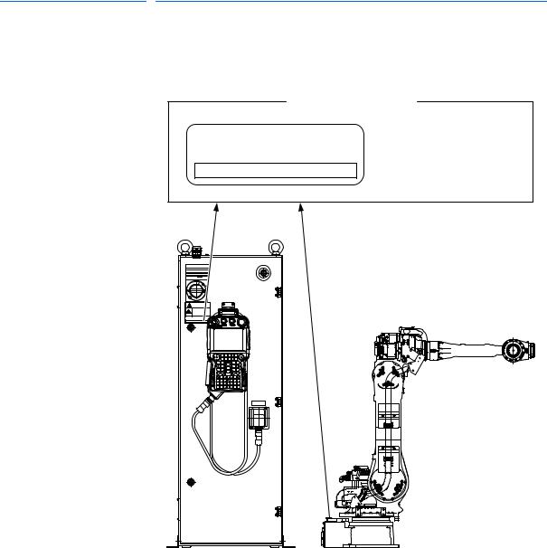
1.2 Order Number Confirmation
Check that the order number of the manipulator corresponds to the
DX100. The order number is indicated on a label as shown below.
Fig. 1-1: Location of Order Number Label
Label (Enlarged View)
THE MANIPULATOR AND THE CONTROLLER SHOULD HAVE SAME ORDER NUMBER.
ORDER NO. 


Check that the manipulator and the DX100 have the same order number.
DX100 |
ER GE NC |
E |
Y |
|
S T O P |
ORDER NO. |
|
X 8 1 |
|
(a) DX 100 (Front View) |
(b) Manipulator (Side View) |
1-2 |
12 of 77 |
HW1480080
158813-1CD
MH80 Manipulator
2 Transport
2 Transport
2.1 Transporting Method
 CAUTION
•Sling and crane or forklift operations must be performed by authorized personnel only.
Failure to observe this caution may result in injury or damage.
•Avoid excessive vibration or shock during transport.
The system consists of precision components. Failure to observe this caution may adversely affect performance.
2.1 Transporting Method
• The mass of the manipulator is approximately 585 kg including the shipping bolts and brackets. Use a wire rope strong enough to withstand the mass.
• The attached eyebolts are designed to support the manipulator mass. Never use them for anything other
NOTE than transporting the manipulator.
• Mount the shipping bolts and brackets before transporting the manipulator.
•With any transportation equipment, make sure to avoid external force on the arm or motor unit when transporting the manipulator.
2-1 |
13 of 77 |
HW1480080

|
|
|
158813-1CD |
|
MH80 Manipulator |
|
2 |
Transport |
|
|
2.1 |
Transporting Method |
||
|
|
|
|
|
2.1.1 |
Using a Crane |
|||
As a rule, when uncrating the manipulator and moving it, a crane should be used. Lift the manipulator with a four-leg bridle sling using the shipping bolts and brackets. Be sure that the manipulator is fixed with the shipping bolts and brackets before transport, and lift it in the posture as shown in
Fig. 2-1 “Transport Using a Crane”.
Fig. 2-1: Transport Using a Crane
Shipping bolts and bracket (Fixed to the manipulator before shipment.)
Hexagon head screw
M12 (8 screws)
2-2 |
14 of 77 |
HW1480080
158813-1CD |
|
MH80 Manipulator |
2 Transport |
2.1Transporting Method
2.1.2Using a Forklift
When using a forklift, the manipulator should be fixed on a pallet with shipping bolts and brackets as shown in Fig. 2-2 “Transport Using a Forklift”. Insert claws into the folklift claw entries of the pallet and lift it. The pallet must be strong enough to support the manipulator.
Transport the manipulator slowly with due caution in order to avoid overturn or slippage.
Fig. 2-2: Transport Using a Forklift
Shipping bolts and bracket 


 (Fixed to the manipulator


 before shipment.)
Screw M20 (8 screws)
Pallet |
Forklift claw entries |
2-3 |
15 of 77 |
HW1480080

|
|
|
158813-1CD |
|
MH80 Manipulator |
|
2 |
Transport |
|
|
|
2.2 |
Shipping Bolts and Brackets |
|
2.2 Shipping Bolts and Brackets
The manipulator is provided with shipping bolts and brackets at positions as shown in the figures in section 2.1 “Transporting Method” on page 2-1, to protect its driving units from various external force during transport.
The shipping brackets are painted yellow.
|
Before turning ON the power, check to be sure that the |
NOTE |
shipping bolts and brackets have been removed. The |
shipping bolts and brackets then must be stored for future |
|
|
use, in the event that the manipulator must be moved again |
|
for relocation. |
2-4 |
16 of 77 |
HW1480080

158813-1CD |
|
MH80 Manipulator |
3 Installation |
3 Installation
 WARNING
•Install the safeguarding.
Failure to observe this warning may result in injury or damage.
•Install the manipulator in a location where the manipulator’s tool or the workpiece held by the manipulator will not reach the wall, safeguarding, or DX100 when the arm is fully extended.
Failure to observe this warning may result in injury or damage.
•Do not start the manipulator or even turn ON the power before it is firmly anchored.
The manipulator may overturn and cause injury or damage.
 CAUTION
•Do not install or operate a manipulator that is damaged or lacks parts.
Failure to observe this caution may cause injury or damage.
•Before turning ON the power, check to be sure that the shipping bolts and brackets explained in section 2.2 “Shipping Bolts and Brackets” on page 2-4 are removed.
Failure to observe this caution may result in damage to the driving parts.
3-1 |
17 of 77 |
HW1480080

|
|
|
158813-1CD |
|
MH80 Manipulator |
|
3 |
Installation |
|
|
|
3.1 |
Installation of Safeguarding |
|
3.1 Installation of Safeguarding
To insure safety, be sure to install the safeguarding. They prevent unforeseen accidents with personnel and damage to equipment. The following is quoted for your information and guidance.
Responsibility for Safeguarding (ISO 10218)
The user of a manipulator or robot system shall ensure that safeguarding is provided and used in accordance with Sections 6, 7, and 8 of this standard. The means and degree of safeguarding, including any redundancies, shall correspond directly to the type and level of hazard presented by the robot system consistent with the robot application. Safeguarding may include but not be limited to safeguarding devices, barriers, interlock barriers, perimeter guarding, awareness barriers, and awareness signals.
3.2 Mounting Procedures for Manipulator Base
The manipulator should be firmly mounted on a baseplate or foundation strong enough to support the manipulator and withstand repulsion forces during acceleration and deceleration. Construct a solid foundation with the appropriate thickness to withstand maximum repulsion force of the manipulator. (Refer toTable 3-1 "Maximum Repulsion Force of the Manipulator at Emergency Stop" andTable 3-2 "Endurance Torque in Operation".)
A baseplate flatness must be kept at 0.5 mm or less: insufficient flatness of installation surface may deform the manipulator shape and affect its functional abilities.
For installation, refer to Fig. 3-1 “Mounting the Manipulator on the Baseplate” or Fig. 3-2 “Mounting the Manipulator on the Floor”.
Table 3-1: Maximum Repulsion Force of the Manipulator at Emergency Stop
Maximum torque in horizontal rotation |
24500 N·m |
(S-axis moving direction) |
(2500 kgf·m) |
|
|
Maximum torque in vertical rotation |
45080 N·m |
(LU-axis moving direction) |
(4600 kgf·m) |
|
|
Table 3-2: Endurance Torque in Operation
Endurance torque in horizontal operation |
6125N·m |
|
(625 kgf·m) |
||
|
||
|
|
|
Endurance torque in vertical operation |
11270 N·m |
|
(1150 kgf·m) |
||
|
||
|
|
3-2 |
18 of 77 |
HW1480080

158813-1CD |
|
MH80 Manipulator |
3 Installation |
3.2Mounting Procedures for Manipulator Base
3.2.1Mounting the Manipulator on the Baseplate
The baseplate should be rugged and durable to withstand maximum repulsion force of the manipulator and to ensure that the manipulator and fixture are in the correct relative position. The thickness of the baseplate is 50 mm or more and an M20 size or larger anchor bolt is recommended. After anchoring the baseplate firmly on the floor, fix the manipulator base to the baseplate with the hexagon head screw M20 (8 screws, length of 70 mm or more is recommended) using mounting holes on the manipulator base. The manipulator base is tapped for eight mounting holes. Tighten the hexagon head bolts and anchor bolts securely so that they will not work loose during operation. For details, refer to Fig. 3-1 “Mounting the Manipulator on the Baseplate”.
Fig. 3-1: Mounting the Manipulator on the Baseplate
Hexagon head screw
M20 (8 screws)
Spring washer
Manipulator base
Washer |
30 |
|
|
|
50 |
 Baseplate
Anchor bolt (M20 or more)
Flatness: 0.5mm or less |
Baseplate |
3-3 |
19 of 77 |
HW1480080
158813-1CD
MH80 Manipulator |
|
3 Installation |
3.2Mounting Procedures for Manipulator Base
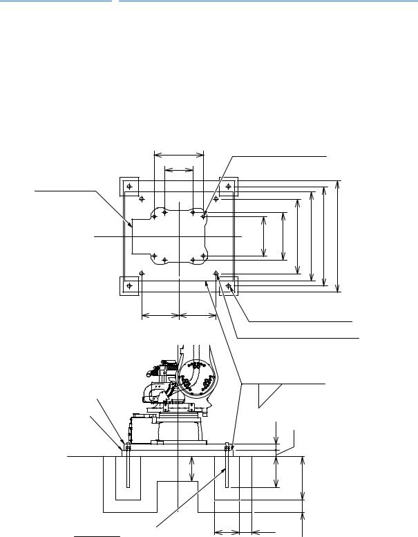
3.2.2Mounting the Manipulator on the Floor
The floor should be strong enough to support the manipulator. Construct a solid foundation with the appropriate thickness to withstand maximum repulsion force of the manipulator shown in Table 3-1 "Maximum Repulsion Force of the Manipulator at Emergency Stop" . As a rough standard, if there is a concrete thickness (floor) of 200 mm or more, the manipulator base can be fixed directly to the floor with anchor bolts M20. Before mounting the manipulator, however, check that the floor is level and that all cracks, etc. are repaired. Any thickness less than 200 mm is insufficient for mounting, even if the floor is concrete.
Fig. 3-2: Mounting the Manipulator on the Floor
400 |
|
Tapped hole M20 (8 holes); |
|
||||
230 |
|
Screw A |
|
|
|
|
|
|
|
|
|
|
|
|
|
Manipulator base |
|
|
|
|
|
|
|
|
|
320 |
385 |
600 |
720 |
800 |
900 |
|
|
|
|
|
|
|
|
300 |
300 |
28 dia.hole (4 holes) (Base B) |
|||||
|
|
||||||
Base A
Base B
Level the floor.
28 dia.hole (4 holes) (Base A)
Tapped hole M24 (4 holes) (Base B);
Screw B
Weld here after installation and adjustment .
10
36 32
FL |
200 |
|
250 |
|
|
|
350 |
||
|
|
|
|
Units: mm |
JA-type anchor bolt M24 |
|
200 |
100 |
100 |
(length: 315) |
|
|||
|
|
Screw A: Screw M20 (length: 70) (8 screws); spring washer, flat washer
Screw B: Screw M24 (length: 70) (4 screws); spring washer
The fixing screws and bases are to be prepared by customer.
3-4 |
20 of 77 |
HW1480080
158813-1CD |
|
|
|
MH80 Manipulator |
3 |
Installation |
|
|
3.3 |
Types of Mounting |
|
|
|
|
|
3.3 |
Types of Mounting |
||
The MOTOMAN-MH80 is available in three ways: floor-mounted (standard), wall-mounted and ceiling-mounted way. For wall-mounted and ceiling-mounted ways, the three points listed below are different from the floor-mounted way.
•S-axis Operating Range
•Fixing the Manipulator Base
•Precautions to Prevent the Manipulator from Falling
3.3.1S-axis Operating Range
For wall-mounted way, the S-axis operating range is ±30°. (The range is adjusted prior to the shipment.)
3.3.2Fixing the Manipulator Base
For walland ceiling-mounted ways, be sure to use eight hexagon socket head cap screws M20 (tensile strength: 1200 N/mm2 or more) when fixing the manipulator base. Use a torque of 402 N•m (41 kgf•m) when tightening the screws.
3.3.3Precautions to Prevent the Manipulator from Falling
For the wallor ceiling-mounted ways, take appropriate measures to avoid the falling of the manipulator in case of emergency. Refer to Fig. 3-3 “Precaution Against Falling” for details.
Fig. 3-3: Precaution Against Falling
 Support for fall prevention
Manipulator base
Hexagon socket head cap
screw M20 (8 screws)
(Tensile strength: 1200 N/mm2 or more)
|
In case of using the wall-/ceiling-mounted way, inform |
NOTE |
Yaskawa of the matter when placing an order. Be sure to |
contact your Yaskawa representative (listed on the back |
|
|
cover of this instruction manual) to perform a wall/ceiling |
|
installation on site. |
3-5 |
21 of 77 |
HW1480080
|
|
|
158813-1CD |
|
MH80 Manipulator |
|
3 |
Installation |
|
|
|
3.4 |
Notes in Mounting the Manipulators on the Ceiling |
|
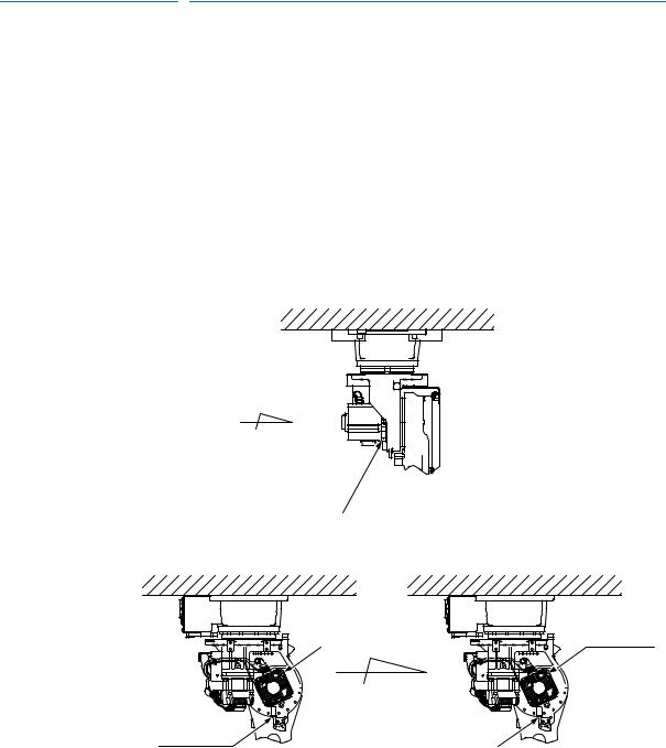
3.4 Notes in Mounting the Manipulators on the Ceiling
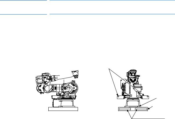
In the case if the manipulator shipped is the floor-mounted way, yet is to be mounted on the ceiling, mounting positions of each part on the view A in the figure below should be changed after installing the manipulator on the ceiling, to prevent a grease leakage from an air breather.
Change the mounting positions of the parts as shown in the figure below.
After installing the manipulator on the ceiling, replace the positions of the parts installed in the L-axes motor base, by switching the positions of the grease cap and the air breather.
Replace the positions of the grease cap and the air breather promptly, to prevent the grease leakage from a hole where a grease cap is to be installed.
Fig. 3-4: Parts Positions for Ceiling Mounted Manipulator
A
Motor base
Grease Cap |
Air Breather |
Air Breather |
Grease Cap |
(Before) |
(After) |
|
View A |
3-6 |
22 of 77 |
HW1480080
158813-1CD |
|
|
|
MH80 Manipulator |
3 |
Installation |
|
|
3.4 |
Notes in Mounting the Manipulators on the Ceiling |
|
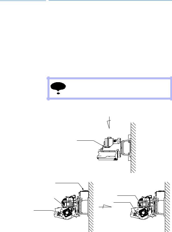
3.5 Notes in Mounting the Manipulators on the Wall
In the case if the manipulator shipped is the floor-mounted way, yet is to be mounted on the wall, mounting positions of each part on the view A in the figure below should be changed after installing the manipulator on the wall, to prevent a grease leakage from an air breather.
Change the mounting positions of the parts as shown in the figure below.
After installing the manipulator on the wall, replace the positions of the parts installed in the motor base, by switching the positions of the grease cap and the air breather.
Replace the positions of the grease cap and the air breather promptly, to prevent the grease leakage from a hole where a grease cap is to be installed.
NOTE |
When used in the wall mounted position, install the |
|
manipulator so that a connector base becomes the top. |
Fig. 3-5: Parts Positions for Wall Mounted Manipulator
A
Motor base
Connector base
Air Breather
Grease Cap
Grease Cap
Air Breather
(Before) |
(After) |
|
View A |
3-7 |
23 of 77 |
HW1480080

|
|
|
158813-1CD |
|
MH80 Manipulator |
|
3 |
Installation |
|
|
|
3.6 |
IP (International Protection) |
|
3.6 IP (International Protection)
For the standard type, environmental resistance for main part of the manipulator conforms to IP54; the wrist part conforms to IP67.
However, for wall-mounted or ceiling mounted ways, environmental resistance for main part of the manipulator does not conform to IP54; environmental resistance for IP65 is optionally available.
3.7 Location
When installing the manipulator, satisfy the following environmental conditions.
• Ambient temperature: 0° to 45°C
• Humidity: 20 to 80%RH at constant temperature
• Free from exposure to water, oil, or dust
• Free from corrosive gas or liquid, or explosive gas or liquid
• Free from excessive vibration (Vibration acceleration: 4.9 m/s2 [0.5 G] or less)
• Free from large electrical noise (plasma)
• Flatness for installation is 0.5 mm or less
3-8 |
24 of 77 |
HW1480080
Loading...