


 Loading...
DX200 OPTIONS
INSTRUCTIONS
FOR ARC SENSOR COMARC FUNCTION
Upon receipt of the product and prior to initial operation, read these instructions thoroughly, and retain for future reference.
MOTOMAN INSTRUCTIONS
MOTOMAN-- INSTRUCTIONS
DX200 INSTRUCTIONS
DX200 OPERATOR’S MANUAL
DX200 MAINTENANCE MANUAL
The DX200 Operator’s manual above corresponds to specific usage.
Be sure to use the appropriate manual.
Part Number: 165557-1CD
Revision: 0
MANUAL NO. |
0 |
|
HW1482187 |
1/54 |
|
|
|

165557-1CD
Arc Sensor Comarc
 MANDATORY
•This manual explains the arc sensor COMARC function of the DX200 system and general operations. Read this manual carefully and be sure to understand its contents before handling the DX200.
•General items related to safety are listed in Chapter 1: Safety of the DX200 Instructions. To ensure correct and safe operation, carefully read the DX200 Instructions before reading this manual.
 CAUTION
•Some drawings in this manual are shown with the protective covers or shields removed for clarity. Be sure all covers and shields are replaced before operating this product.
•The drawings and photos in this manual are representative examples and differences may exist between them and the delivered product.
•YASKAWA may modify this model without notice when necessary due to product improvements, modifications, or changes in specifications.
•If such modification is made, the manual number will also be revised.
•If your copy of the manual is damaged or lost, contact a YASKAWA representative to order a new copy. The representatives are listed on the back cover. Be sure to tell the representative the manual number listed on the front cover.
•YASKAWA is not responsible for incidents arising from unauthorized modification of its products. Unauthorized modification voids your product's warranty.
ii
HW1482187 2/54

165557-1CD
Arc Sensor Comarc
Notes for Safe Operation
Read this manual carefully before installation, operation, maintenance, or inspection of the DX200.
In this manual, the Notes for Safe Operation are classified as “WARNING”, “CAUTION”, “MANDATORY”, or “PROHIBITED”.
 WARNING
 CAUTION
Indicates a potentially hazardous situation which, if not avoided, could result in death or serious injury to personnel.
Indicates a potentially hazardous situation which, if not avoided, could result in minor or moderate injury to personnel and damage to equipment. It may also be used to alert against unsafe practices.
 MANDATORY
 PROHIBITED
Always be sure to follow explicitly the items listed under this heading.
Must never be performed.
Even items described as “CAUTION” may result in a serious accident in some situations.
At any rate, be sure to follow these important items
To ensure safe and efficient operation at all times, be sure to NOTE follow all instructions, even if not designated as "CAUTION"
and "WARNING".
iii
HW1482187 3/54

165557-1CD
Arc Sensor Comarc
 WARNING
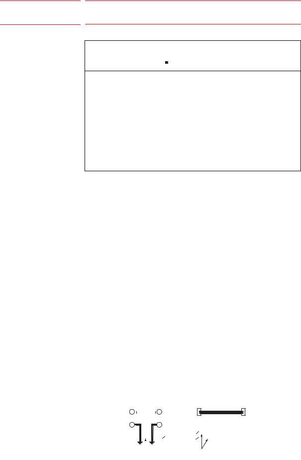
•Before operating the manipulator, check that servo power is turned OFF pressing the emergency stop buttons on the front door of the DX200 and the programming pendant.
When the servo power is turned OFF, the SERVO ON LED on the programming pendant is turned OFF.
Injury or damage to machinery may result if the emergency stop circuit cannot stop the manipulator during an emergency. The manipulator should not be used if the emergency stop buttons do not function.
Figure 1: Emergency Stop Button
•Once the emergency stop button is released, clear the cell of all items which could interfere with the operation of the manipulator. Then turn the servo power ON.
Injury may result from unintentional or unexpected manipulator motion.
Figure 2: Release of Emergency Stop
 TURN
TURN
•Observe the following precautions when performing teaching operations within the P-point maximum envelope of the manipulator:
–View the manipulator from the front whenever possible.
–Always follow the predetermined operating procedure.
–Keep in mind the emergency response measures against the manipulator’s unexpected motion toward you.
–Ensure that you have a safe place to retreat in case of emergency.
Improper or unintended manipulator operation may result in injury.
•Confirm that no person is present in the P-point maximum envelope of the manipulator and that you are in a safe location before:
–Turning ON the power for the DX200.
–Moving the manipulator with the programming pendant.
–Running the system in the check mode.
–Performing automatic operations.
•Injury may result if anyone enters the P-point maximum envelope of the manipulator during operation. Always press an emergency stop button immediately if there is a problem.
The emergency stop buttons are located on the right of front door of the DX200 and the programming pendant.
iv
HW1482187 4/54

165557-1CD
Arc Sensor Comarc
 CAUTION
•Perform the following inspection procedures prior to conducting manipulator teaching. If problems are found, repair them immediately, and be sure that all other necessary processing has been performed.
–Check for problems in manipulator movement.
–Check for damage to insulation and sheathing of external wires.
•Always return the programming pendant to the hook on the cabinet of the DX200 after use.
The programming pendant can be damaged if it is left in the manipulator's work area, on the floor, or near fixtures.
•Read and understand the Explanation of Warning Labels in the DX200 Instructions before operating the manipulator.
Definition of Terms Used Often in This Manual
The MOTOMAN is the YASKAWA industrial robot product.
The MOTOMAN usually consists of the manipulator, the controller, the programming pendant, and supply cables.
In this manual, the equipment is designated as follows.
Equipment |
Manual Designation |
|
|
DX200 controller |
DX200 |
|
|
DX200 programming pendant |
Programming pendant |
|
|
Cable between the manipulator and the |
Manipulator cable |
controller |
|
|
|
v
HW1482187 5/54

165557-1CD
Arc Sensor Comarc
Descriptions of the programming pendant keys, buttons, and displays are shown as follows:
Equipment |
|
Manual Designation |
|
|
|
Programming |
Character Keys |
The keys which have characters or its |
Pendant |
/Symbol Keys |
symbol printed on them are denoted with [ ]. |
|
|
ex. [ENTER] |
|
|
|
|
Axis Keys |
[Axis Key] and [Numeric Key] are generic |
|
/Numeric Keys |
names for the keys for axis operation and |
|
|
number input. |
|
|
|
|
Keys pressed |
When two keys are to be pressed |
|
simultaneously |
simultaneously, the keys are shown with a |
|
|
“+” sign between them, |
|
|
ex. [SHIFT]+[COORD] |
|
|
|
|
Displays |
The menu displayed in the programming |
|
|
pendant is denoted with { }. |
|
|
ex. {JOB} |
|
|
|
Description of the Operation Procedure
In the explanation of the operation procedure, the expression "Select • • • " means that the cursor is moved to the object item and the SELECT key is pressed, or that the item is directly selected by touching the screen.
Registered Trademark
In this manual, names of companies, corporations, or products are trademarks, registered trademarks, or brand names for each company or corporation. The indications of (R) and TM are omitted.
vi
HW1482187 6/54

165557-1CD
Arc Sensor Comarc
|
|
|
Table of Contents |
|
|
|
|
|
|
|
|
1 |
Installation....................................................................................................................................... |
1-1 |
|||
|
1.1 |
Starting Point Detecting Unit.............................................................................................. |
1-2 |
||
|
1.2 |
Current Detecting Unit ....................................................................................................... |
1-3 |
||
2 |
DX200 Wiring.................................................................................................................................. |
2-1 |
|||
|
2.1 |
Connection Diagnosis........................................................................................................ |
2-4 |
||
3 |
Arc Sensor Function ....................................................................................................................... |
3-1 |
|||
|
3.1 |
Basic Understanding of the Arc Sensor............................................................................. |
3-1 |
||
|
|
3.1.1 Left and Right Path Correction ............................................................................. |
3-1 |
||
|
|
3.1.2 Up and Down Path Correction.............................................................................. |
3-2 |
||
|
|
3.1.3 Applicable Range of the Arc Sensor..................................................................... |
3-2 |
||
|
3.2 |
Main Operations for the Arc Sensor Function.................................................................... |
3-3 |
||
|
|
3.2.1 Job Preparation for Welding and Adjustment of Welding Conditions ................... |
3-3 |
||
|
|
3.2.1.1 Registration of Arc Sensing Instructions ................................................. |
3-4 |
||
|
3.3 |
Arc Sensor Function and Weaving Condition .................................................................... |
3-5 |
||
|
|
3.3.1 Path Correction Direction and Weaving Basis Coordinate System ...................... |
3-5 |
||
|
|
3.3.2 Cases that Require the Registration of Reference Points .................................... |
3-7 |
||
4 |
Registration of Instructions ............................................................................................................. |
4-1 |
|||
|
4.1 |
COMARCON (Sensing Start Instruction)........................................................................... |
4-1 |
||
|
4.2 |
COMARCOF (Sensing End Instruction) ............................................................................ |
4-4 |
||
|
4.3 |
COMARCSET (Sensing Condition Change)...................................................................... |
4-5 |
||
|
4.4 |
REFP (Reference Point Registration)................................................................................ |
4-7 |
||
5 |
Phase Compensation Value ........................................................................................................... |
5-1 |
|||
|
5.1 |
Job Preparation for Measurement of Phase Compensation Value.................................... |
5-1 |
||
|
5.2 |
Measurement and Registration of a Phase Compensation Value ..................................... |
5-3 |
||
6 Measurement and Registration of Sensing Conditions................................................................... |
6-1 |
||||
|
6.1 |
Job for Measuring Sensing Conditions.............................................................................. |
6-1 |
||
|
6.2 |
Measurement of Sensing Conditions................................................................................. |
6-3 |
||
|
6.3 |
Registration of Sensing Conditions.................................................................................... |
6-4 |
||
|
6.4 |
Adjustment of Sensing Conditions..................................................................................... |
6-5 |
||
|
6.5 |
Results of Arc Sensing ...................................................................................................... |
6-6 |
||
vii
HW1482187 7/54
|
|
|
|
|
165557-1CD |
|
Arc Sensor Comarc |
|
Table of Contents |
|
|
||
|
|
|
|
|
|
|
|
|
|
|
|
|
|
7 |
COMARC Condition File ................................................................................................................. |
7-1 |
|
|||
|
7.1 |
COMARC Condition File .................................................................................................... |
7-1 |
|
||
|
7.2 |
File Operation .................................................................................................................... |
7-3 |
|
||
|
|
7.2.1 Display of a File .................................................................................................... |
7-3 |
|
||
|
|
7.2.2 Editing of a File ..................................................................................................... |
7-3 |
|
||
|
|
7.2.2.1 Editing of “CORRECTION SELECT” and “CONDITION” ........................ |
7-3 |
|
||
|
|
7.2.2.2 Editing of Other Items.............................................................................. |
7-3 |
|
||
|
|
7.2.3 Initialization of the File .......................................................................................... |
7-4 |
|
||
8 Modification of the Settings in COMARC Function ......................................................................... |
8-1 |
|
||||
9 |
Instruction List................................................................................................................................. |
9-1 |
|
|||
10 |
Parameter List............................................................................................................................. |
10-1 |
|
|||
11 |
Alarm Message List..................................................................................................................... |
11-1 |
||||
viii
HW1482187 8/54

165557-1CD |
|
Arc Sensor Comarc |
1 Installation |
1 Installation
 WARNING
•Since detected voltage (200 V), welding current, and welding voltage are applied to the starting point detecting unit, install the unit securely so that it does not fall.
Failure to observe this warning may result in an electric shock or damage to the unit.
For installation methods of a starting point detecting unit and a current detecting unit, refer to Fig.1-1 Installation of Starting Point Detecting Unit and Fig.1-2 Installation of Current Detecting Unit.
The starting point detecting unit should be installed outside of the manipulator interference area.
1-1
HW1482187 9/54

|
|
|
165557-1CD |
|
Arc Sensor Comarc |
|
1 |
Installation |
|
|
|
1.1 |
Starting Point Detecting Unit |
|
1.1 Starting Point Detecting Unit
The starting point detecting unit should be installed on the side of the welder.
When installing the unit on a welder or other devices, use a fixture to fix the unit with the mounting holes located on both sides of the unit in order to prevent the unit from falling.
Fig. 1-1: Installation of Starting Point Detecting Unit
3 |
4 |
5 |
|
1NL 1LED |
1PEI |
Air vent |
|
|
|||
3 |
|
|
|
|
ON |
1FU |
|
1SW |
OFF |
|
|
1A |
|
||
|
1 |
|
2 |
400
400
Front View
Eyebolt M8 (2 eyebolts)
Air vent
150 |
(38) |
500
Side View
Units: mm
1-2
HW1482187 10/54
165557-1CD |
|
|
|
Arc Sensor Comarc |
1 |
Installation |
|
|
1.2 |
Current Detecting Unit |
|
|
|
|
|
1.2 |
Current Detecting Unit |
||
Fig. 1-2: Installation of Current Detecting Unit
18
38
18
21
.5 33
50
100
Front View
80 |
100
Units: mm
Side View
1-3
HW1482187 11/54

165557-1CD
Arc Sensor Comarc |
|
2 DX200 Wiring |
2 DX200 Wiring
 WARNING
•Before connecting the inter-unit cables and the welding cables, be sure to turn OFF the power supply to the DX200 and the welder.
Failure to observe this warning may result in an electric shock.
•Special attention should be paid during starting point detection, since 200 VDC is applied across the wire and the workpiece (welding jig).
Failure to observe this warning may result in an electric shock.
•Do not place any object directly on the cable of the starting point detecting unit.
Failure to observe this warning may result in an injury or damage caused by the disconnection of the cable.
•Attach the cable of the starting point detecting unit for the wire feeder with the wire stand, to protect it from robot movement.
If interference between the cable and the peripheral devices cannot be avoided, cover the cable with a rubber plate or spiral tube, etc.
Failure to observe this warning may result in an electric shock caused by damage to the cable, or an injury or damage caused by malfunction.
•Do not lay the cable of the starting point detecting unit directly on the floor, but install them in a pit or duct, or attach the cable with a protective cover.
Failure to observe this warning may result in an injury or damage to the cable.
•Since a high current flows through the welding cable, separate it from the cables of the control circuit system. If the cables cannot be separated, take preventative measures such as using metallic ducts or tubes on the cables of the control circuit system.
2-1
HW1482187 12/54
165557-1CD |
|
Arc Sensor Comarc |
2 DX200 Wiring |
 CAUTION
•Insert the inter-unit cable on the starting point detecting unit side, firmly to the connector, and fix it securely by tightening the coupling nut.
•Fix the other cables connected to the terminal stand securely by tightening the terminal screws.
Failure to observe these cautions may result in an electric shock, an injury, or damage caused by malfunctioning.
•After connected, be sure to reinstall the terminal covers of starting point detecting unit and welder.
Failure to observe this caution may result in an electric shock.
Wire the unit in the following manner, referring to Fig.2-1 Configuration
Diagram of Starting Point Detecting Unit and Fig.2-2 Configuration
Diagram of Current Detecting Unit.
Starting Point Detecting Unit
1.Connect the starting point detecting unit to the DX200.
2.Connect the plus terminal of the starting point detecting unit to the plus terminal of the welder.
3.Connect the minus terminal of the starting point detecting unit to the torch power supply unit on the wire feeder.
4.Connect the front terminal of the stand of the starting point detecting unit to the welding voltage detecting terminal on the wire feeder in the case of a floor-standing type, and to the terminal stand in the welder in the case of a welder-side hung type, respectively.
Fig. 2-1: Configuration Diagram of Starting Point Detecting Unit
DX200
Welder |
|
|
|
|
|
|
|||||||||||
|
|
|
|
|
|
|
|
|
|
|
Starting point |
|
|
|
|
|
|
|
|
Welding cable |
detecting unit |
|
Inter-unit cable |
|
|||||||||||
|
|
|
1CN |
|
YCP02 board |
||||||||||||
|
|
|
|
|
|
|
|
|
|
|
|
|
|
|
|
||
|
|
|
|
|
|
|
|
|
|
|
|
|
|
|
|
||
|
|
|
|
|
|
|
|
|
|
|
E |
SE1 |
|
|
To the torch |
|
|
|
|
|
|
|
|
|
|
|
|
|
|
|
|
||||
|
|
|
|
|
|
|
|
|
|
|
|
|
|
||||
|
|
|
|
|
|
|
|
|
|
|
|
|
|
||||
|
|
|
|
|
|
|
|
|
|
|
|
|
|
||||
|
|
|
|
|
|
|
|
|
|
|
SE2 |
|
|
To the welder |
|
||
|
|
|
|
|
|
|
|
|
|
|
|
|
|
|
|||
To the workpiece |
To the wire feeder |
|
|
|
|
|
|||||||||||
|
|
|
|
|
|
|
|
|
|
|
|
Cable for welding voltage detection |
|||||
|
|
|
|
|
|
|
|
|
|||||||||
|
Ground cable |
|
|
|
|
|
|
||||||||||
2-2
HW1482187 13/54

165557-1CD
Arc Sensor Comarc |
|
2 DX200 Wiring |
Current Detecting Unit
1.Connect the connection cable of current detecting unit to the DX200.
2.Connect the plus cable of the current detecting unit to the + terminal of the welder.
Connect the other cable to the welding cable from the torch power supply unit on the wire feeder, and tape it with an insulating tape.
Fig. 2-2: Configuration Diagram of Current Detecting Unit
DX200
Welder
Current detecting unit

 YCP02 board
To the workpiece To the wire feeder
2-3
HW1482187 14/54

165557-1CD |
|
|
|
Arc Sensor Comarc |
2 |
DX200 Wiring |
|
|
2.1 |
Connection Diagnosis |
|
2.1 Connection Diagnosis
To confirm a connection, perform a diagnosis of the input status to the YCP02 board.
(The YCP02 board is a board for the COMARC.)
Use the following procedure to call the YCP02 I/O status display. 1. Select {IN/OUT} from the main menu.
2. Select {YCP02 I/O}.
– The YCP02 I/O STATUS window appears.
–In this display, confirm the values read-by the YCP02 board’s A/D converter and the general I/O status.
–Eight channels are provided for the A/D converter.
–Four points for input and output respectively are provided for general I/O.
–Use the YCP02 I/O STATUS window for the following purposes;
•Check whether the A/D converter is correctly operating.
•Check whether the cables for the current detecting unit are correctly connected.
For an incorrect |
When welding is performed, the A/D |
connection |
data shows a negative value (-). |
For normal status |
When welding is performed by |
|
executing the normal ARCON/ARCOF, |
|
the A/D data show a positive value (+). |
|
(Execute a job without using |
|
COMARCON/COMARCOF.) |
|
|
|
|
|
• The YCP02 I/O STATUS window can be called only in |
NOTE |
"MANAGEMENT MODE". |
|
• When the icon {YCP02 I/O} does not appear, switch the security mode to "MANAGEMENT MODE".
2-4
HW1482187 15/54

165557-1CD
Arc Sensor Comarc |
|
3 |
Arc Sensor Function |
|
|
3.1 |
Basic Understanding of the Arc Sensor |
3Arc Sensor Function
3.1Basic Understanding of the Arc Sensor
For welding with a power supply that has constant voltage characteristics, the welding current fluctuates as the distance L changes as shown below. Distance L is the distance between the tip and the base metal. The arc sensor function uses these characteristics.
Welding current
High  Low
Low
Tip
Consumable |
|
electrode (wire) |
L |
Arc |
|
Base metal
3.1.1Left and Right Path Correction
During welding with the torch weaving from side to side, an equal amount welding current flows on points and if the distance L is the same on both sides (points and ) due to the aforementioned characteristics.
1 2
Welding current: 1 = 2 , (When the distance between the tip and the base metal is the same on both sides.)
If the distances L are different at points and , different currents flow at these two points as shown below.
The arc sensor checks the welding currents at points and and corrects the path to equalize the values.
|
Direction of path |
Direction of path |
|
|
correction |
correction |
|
1 |
2 |
1 |
2 |
|
|
|
|
|
|
|
|
|
|
|
|
|
|
|
|
|
|
|
|
|
|
|
|
|
|
|
|
|
|
|
|
|
|
|
|
|
|
|
|
|
|
|
|
|
|
|
|
|
|
|
|
|
|
|
|
|
|
|
|
|
|
|
|
|
|
|
|
|
|
|
|
|
|
|
|
|
|
|
|
|
|
|
|
Welding current 1 > 2 (shifted to the left) |
Welding current 1 < 2 (shifted to the right) |
||||||||||||
3-1
HW1482187 16/54
165557-1CD |
|
|
|
Arc Sensor Comarc |
3 |
Arc Sensor Function |
|
|
3.1 |
Basic Understanding of the Arc Sensor |
|
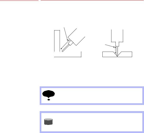
3.1.2 Up and Down Path Correction
During welding with the torch moving up and down, the arc sensor checks the welding currents at any 2 points, an upper point and a lower point, and corrects the path to equalize the values.
Up and down path correction
Up and down path correction
3.1.3Applicable Range of the Arc Sensor
The applicable metal thickness and joint are as follows.
Metal thickness: 3.2 mm or more
Joint: T joint, Lap joint
Speed: 1 m/min or less
NOTE |
The arc sensor function can be used except that the droplet |
|
transfer status is a spray transfer. |
SUPPLE-
MENT
•The droplet transfer means that the welded tip of wire (droplet) transfers to the base metal.
•For the status of droplet transfer, there are dip transfer, spray transfer, and etc.
3-2
HW1482187 17/54
Loading...