


 Loading...
YASKAWA
Machine Controller MP920
Motion Module
USER'S MANUAL
YASKAWA |
MANUAL NO. SIEZ-C887-2.5C |

Copyright © 1999 YASKAWA ELECTRIC CORPORATION
All rights reserved. No part of this publication may be reproduced, stored in a retrieval system, or transmitted, in any form, or by any means, mechanical, electronic, photocopying, recording, or otherwise, without the prior written permission of Yaskawa. No patent liability is assumed with respect to the use of the information contained herein. Moreover, because Yaskawa is constantly striving to improve its high-quality products, the information contained in this manual is subject to change without notice. Every precaution has been taken in the preparation of this manual. Nevertheless, Yaskawa assumes no responsibility for errors or omissions. Neither is any liability assumed for damages resulting from the use of the information contained in this publication.

Using this Manual
Please read this manual to ensure correct usage of the MP920 system. Keep this manual in a safe place for future reference.
Overview
This manual describes the Motion Modules designed for MP920 Machine Controller. The following Motion Modules can be used with MP920 Machine Controller.
•SVA-01A 4-axis Servo Module
•SVA-02A 2-axis Servo Module
•SVB-01 MECHATROLINK Interface Servo Module
•PO-01 Pulse Output Module
This manual describes the following items required to use these Motion Modules.
•Motion Module setup
•Installation and connection methods
•Parameters
•Troubleshooting
Read this manual carefully to ensure that motion control is correctly performed using the MP920 Machine Controller. Also, keep this manual in a safe place so that it can be referred to whenever necessary.
Intended Audience
This manual is intended for the following users.
•Those responsible for estimating the MP920 system
•Those responsible for deciding whether to apply the MP920 system
•Those responsible for designing the MP920 system so that it can be mounted in the control and operating panels
•Those responsible for making, inspecting, testing, adjusting, and maintaining the control and operating panels in which the MP920 is mounted
Basic Terms
Unless otherwise specified, the following definitions are used:
•MP920 = MP920 Machine Controller
• |
PC: |
Programmable Logic Controller |
• |
MPE720: The Programming Device Software or a Programming Device (i.e., a personal |
|
|
|
computer) running the Programming Device Software |
•PLC = Programmable Logic Controller
•“ ” in “MOV [axis1]...” represents numeric data for axis 1.
iii

Visual Aids
The following aids are used to indicate types of information for easier reference.
IMPORTANT
INFO
 EXAMPLE
TERMS
Indicates important information that should be memorized.
Indicates supplemental information.
Indicates application examples.
Describes technical terms that are difficult to understand, or in the text without an explanation being given.
Indication of Reverse Signals
In this manual, the names of reverse signals (ones that are valid when low) are written with a forward slash (/) before the signal name, as shown in the following example:
• |
S-ON |
|
= /S-ON |
• |
|
= /P-CON |
|
P-CON |
|||
iv

Related Manuals
Refer to the following related manuals as required.
Thoroughly check the specifications, restrictions, and other conditions of the product before attempting to use it.
Manual Name |
Manual Number |
Contents |
Machine Controller MP920 User’s |
SIEZ-C887-2.1 |
Describes the design and maintenance for |
Manual: Design and Maintenance |
|
the MP920 Machine Controller. |
Machine Controller MP920 |
SIEZ-C887-2.6 |
Describes the functions, specifications, and |
Communications Module User’s Manual |
|
usage of the MP920 Communications Mod- |
|
|
ules (215IF, 217IF, and 218IF). |
Machine Controller MP900/MP2000 |
SIEZ-C887-1.2 |
Describes the instructions used in MP900/ |
Series Ladder Logic Programming |
|
MP2000 Series ladder logic programming. |
User’s Manual |
|
|
Machine Controller MP900/MP2000 |
SIEZ-C887-1.3 |
Describes the motion programming language |
Series Motion Programming |
|
used for MP900/MP2000 Series Machine |
User’s Manual |
|
Controllers. |
Machine Controller MP900/MP2000 |
SIEPC88070005 |
Describes how to install and operate the |
Series User’s Manual |
|
MP900/MP2000 Series programming sys- |
MPE720 Software for Programming |
|
tem MPE720. |
Device |
|
|
v
Safety Information
The following conventions are used to indicate precautions in this manual. Failure to heed provided in this manual can result in serious or possibly even fatal injury or damage to he products or to related equipment and systems.

 WARNING

 CAUTION
Indicates precautions that, if not heeded, could possibly result in loss of life, serious injury.
Indicates precautions that, if not heeded, could result in relatively serious or minor injury, damage to the product, or faulty operation.
In some situations, the precautions indicated could have serious consequences if not heeded.

 PROHIBITED

 MANDATORY
Indicates prohibited actions that must not be performed. For example, this symbol would be used as follows to indicate that fire is
prohibited:  .
.
Indicates compulsory actions that must be performed. For example, this symbol would be used as follows to indicate that grounding is
compulsory:  .
.
The warning symbols for ISO and JIS standards are different, as shown below.
ISO |
JIS |
|
|
|
|
The ISO symbol is used in this manual.
Both of these symbols appear on warning labels on Yaskawa products. Please abide by these warning labels regardless of which symbol is used.
vi
Safety Precautions
This section describes precautions to ensure the correct application of the product. Before installing, operating, maintaining, or inspecting the product, always read this manual and all other documents provided to ensure correct work procedures and application. Before using the equipment, familiarize yourself with equipment details, safety information, and all other precautions.
Handling
 CAUTION
•Do not subject the product to halogen gases, such as fluorine, chlovine, bromine, and iodine, at any time even during transportation or installation.
Failure to observe this caution may cause damage or failure of the product.
Installation
 CAUTION
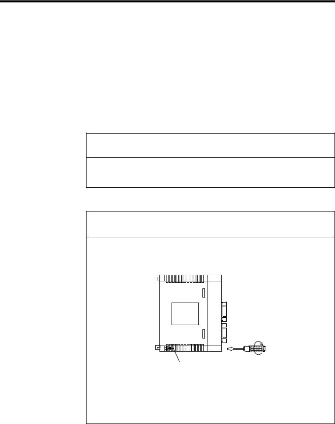
•Firmly tighten the Module mounting screws and terminal block mounting screws to prevent them from loosening during operation.
Loose screws may result in a malfunction of the MP920.
Module mounting screw
(Use an M4 Phillips screw driver.)
•Always turn OFF the power supply to the Module before installing it.
•Insert the connectors of the cables that are to be connected to the MP920 Modules and secure them well.
Incorrect insertion of the connectors may result in a malfunction of the MP920.
vii
Wiring
 CAUTION
•Always connect a power supply that meets the given specifications.
Connecting an inappropriate power supply may cause fires.
•Wiring must be performed by qualified personnel.
Incorrect wiring may cause fires, product failure, or electrical shocks.
•Do not accidentally leave foreign matter such as wire chips on the Mounting Base or in the Module when wiring.
This may cause fires, failures, and malfunctions.
 MANDATORY
•Always ground the FG terminal to a ground resistance 100Ω or less.
Failure to ground the MP920 may result in electrical shocks or malfunctioning.
Select, separate, and lay external cables correctly.
•Consider the following items when selecting the I/O signal lines (external cables) to connect the MP920 Module to external devices.
•Mechanical strength
•Noise interference
•Wiring distance
•Signal voltage, etc.
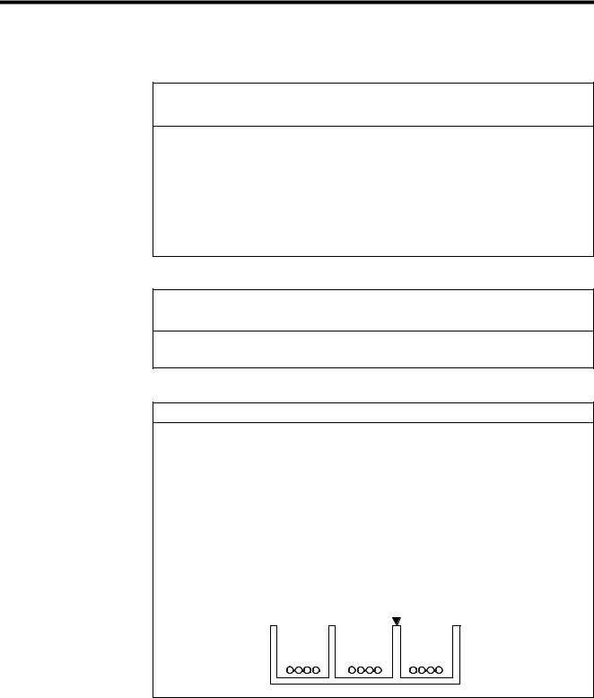
•Separate the I/O signal lines from the power lines both inside and outside the control panel to reduce the influence of noise from the power lines.
If the I/O signal lines and power lines are not separated properly, malfunctioning may result.
Example of Separated External Cables
|
|
|
|
Steel separator |
|
|
|
|
|
Power |
General |
|
Digital I/O |
|
|
||||
circuit |
control cir- |
|
signal |
|
cables |
cuit cables |
|
cables |
|
viii

Application
 WARNING
•Do not touch any Module terminals when the system power is ON.
There is a risk of electrical shock.
 CAUTION
•Do not attempt to modify the MP920 programs, force outputs, switch between RUN and STOP, or perform other similar operations while the MP920 is operating without knowing the direct and indirect consequences of the operation.
Incorrect programming or operation may damage the equipment or cause an accident.
Maintenance
 WARNING
•Make sure that the polarity of the Module’s built-in battery is correct. The battery must be installed correctly and must not be charged, disassembled, heated, thrown into fire, or short-circuited.
Improper handling may cause the battery to explode or ignite.
 PROHIBITED
•Do not attempt to disassemble or modify the MP920 Modules in any way.
Doing so can cause fires, product failure, or malfunctions.
•The customer must not replace any built-in fuses.
If the customer replaces a built-in fuse, the MP920 Module may malfunction or break down. The built-in fuse must always be replaced by Yaskawa service staff.
ix

General
Always note the following to ensure safe use.
•MP920 was not designed or manufactured for use in devices or systems directly related to human life. Users who intend to use the product described in this manual for special purposes such as devices or systems relating to transportation, medical, space aviation, atomic power control, or underwater use must contact Yaskawa Electric Corporation beforehand.
•MP920 has been manufactured under strict quality control guidelines. However, if this product is to be installed in any location in which a failure of MP920 involves a life and death situation or in a facility where failure may cause a serious accident, safety devices MUST be installed to minimize the likelihood of any accident.
•Drawings in this manual show typical product examples that may differ somewhat from the product delivered.
•This manual may change without prior notice due to product improvements and specification changes or for easier use. We will update the manual number of the manual and issue revisions when changes are made. The revision number of the revised manual appears on the back of the manual.
•Contact your nearest Yaskawa sales representative or the dealer from whom you purchased the product and quote the manual number on the front page of the manual if you need to replace a manual that was lost or destroyed.
•Contact your nearest Yaskawa sales representative or the dealer from whom you purchased the product to order new nameplates whenever a nameplate becomes worn or damaged.
•Products modified by the customer are not covered by the Yaskawa warranty, nor does Yaskawa assume any liability for injury or damage that may result from such modifications.
x
CONTENTS
Using this Manual- - - - - - - - - - - - - - - - - - - - - - - - - - - - - - - - - - - - - - - iii Safety Information - - - - - - - - - - - - - - - - - - - - - - - - - - - - - - - - - - - - - - vi Safety Precautions - - - - - - - - - - - - - - - - - - - - - - - - - - - - - - - - - - - - - vii
1 Overview of Motion Modules
1.1 Module Overview and Features - - - - - - - - - - - - - - - - - - - - - 1-2
1.1.1 Motion Modules - - - - - - - - - - - - - - - - - - - - - - - - - - - - - - - - - - - - - - -1-2
1.1.2 SVA-01A Module - - - - - - - - - - - - - - - - - - - - - - - - - - - - - - - - - - - - - -1-3
1.1.3 SVA-02A Module - - - - - - - - - - - - - - - - - - - - - - - - - - - - - - - - - - - - - -1-4
1.1.4 SVB-01 Module - - - - - - - - - - - - - - - - - - - - - - - - - - - - - - - - - - - - - - -1-6
1.1.5 PO-01 Module - - - - - - - - - - - - - - - - - - - - - - - - - - - - - - - - - - - - - - - -1-8
1.2 System Configuration - - - - - - - - - - - - - - - - - - - - - - - - - - - - 1-9
1.2.1 System Configuration Examples - - - - - - - - - - - - - - - - - - - - - - - - - - -1-9
1.3 Specifications- - - - - - - - - - - - - - - - - - - - - - - - - - - - - - - - - 1-10
1.3.1 General Specifications - - - - - - - - - - - - - - - - - - - - - - - - - - - - - - - - -1-10
1.3.2 Function Lists- - - - - - - - - - - - - - - - - - - - - - - - - - - - - - - - - - - - - - - - 1-11
2 Motion Control
2.1 Overview of Motion Control - - - - - - - - - - - - - - - - - - - - - - - - 2-2
2.1.1 Motion Control for the MP920 - - - - - - - - - - - - - - - - - - - - - - - - - - - - -2-2 2.1.2 Motion Control Methods - - - - - - - - - - - - - - - - - - - - - - - - - - - - - - - - -2-4 2.1.3 Examples of Motion Control Applications - - - - - - - - - - - - - - - - - - - - -2-5
2.2 Control Modes - - - - - - - - - - - - - - - - - - - - - - - - - - - - - - - - - 2-7
2.2.1 Overview of Control Modes - - - - - - - - - - - - - - - - - - - - - - - - - - - - - - -2-7
2.2.2 Speed Reference Output Mode - - - - - - - - - - - - - - - - - - - - - - - - - - - -2-8
2.2.3 Torque Reference Output Mode - - - - - - - - - - - - - - - - - - - - - - - - - - - 2-12
2.2.4 Phase Control Mode - - - - - - - - - - - - - - - - - - - - - - - - - - - - - - - - - - -2-15
2.2.5 Zero Point Return Mode - - - - - - - - - - - - - - - - - - - - - - - - - - - - - - - -2-22
2.3 Position Control - - - - - - - - - - - - - - - - - - - - - - - - - - - - - - - 2-26
2.3.1 Prerequisites for Position Control - - - - - - - - - - - - - - - - - - - - - - - - - -2-26
2.3.2 Position Control Without Using Motion Commands - - - - - - - - - - - - -2-41
2.4 Position Control Using Motion Commands - - - - - - - - - - - - 2-45
2.4.1 Overview of Motion Commands - - - - - - - - - - - - - - - - - - - - - - - - - - -2-45 2.4.2 Positioning (POSING) - - - - - - - - - - - - - - - - - - - - - - - - - - - - - - - - - -2-48 2.4.3 External Positioning (EX_POSING) - - - - - - - - - - - - - - - - - - - - - - - -2-51 2.4.4 Zero Point Return (ZRET) - - - - - - - - - - - - - - - - - - - - - - - - - - - - - - -2-55 2.4.5 Interpolation (INTERPOLATE, END_OF_INTERPOLATE) - - - - - - - -2-70 2.4.6 Interpolation with Position Detection (LATCH) - - - - - - - - - - - - - - - - -2-73 2.4.7 Fixed Speed Feed (FEED)- - - - - - - - - - - - - - - - - - - - - - - - - - - - - - -2-74 2.4.8 Fixed Length Feed (STEP) - - - - - - - - - - - - - - - - - - - - - - - - - - - - - -2-77 2.4.9 Zero Point Setting (ZSET) - - - - - - - - - - - - - - - - - - - - - - - - - - - - - - -2-81
xi

3 Motion Module Allocations and Setup
3.1 Allocations and Configuration Definitions - - - - - - - - - - - - - - 3-2
3.1.1 Motion Module Allocation Method - - - - - - - - - - - - - - - - - - - - - - - - - - 3-2
3.1.2 Setting Module Definitions - - - - - - - - - - - - - - - - - - - - - - - - - - - - - - - 3-4
3.1.3 Saving Module Definitions - - - - - - - - - - - - - - - - - - - - - - - - - - - - - - - 3-6
3.2 Individual Module Definitions - - - - - - - - - - - - - - - - - - - - - - - 3-7
3.2.1 MECHATROLINK Definitions - - - - - - - - - - - - - - - - - - - - - - - - - - - - - 3-7
3.2.2 Setting Motion Parameters - - - - - - - - - - - - - - - - - - - - - - - - - - - - - - 3-10
4 Parameters
4.1 Overview of Parameters - - - - - - - - - - - - - - - - - - - - - - - - - - 4-2
4.1.1 Parameter Classifications - - - - - - - - - - - - - - - - - - - - - - - - - - - - - - - - 4-2
4.1.2 Modules and Motion Parameter Registers - - - - - - - - - - - - - - - - - - - - 4-3
4.2 Parameter List by Module - - - - - - - - - - - - - - - - - - - - - - - - - 4-5
4.2.1 Motion Fixed Parameters - - - - - - - - - - - - - - - - - - - - - - - - - - - - - - - - 4-5 4.2.2 Motion Setting Parameters - - - - - - - - - - - - - - - - - - - - - - - - - - - - - - 4-10 4.2.3 Motion Monitoring Parameters - - - - - - - - - - - - - - - - - - - - - - - - - - - 4-18
5 SVA Module Specifications and Handling
5.1 SVA-01A Module - - - - - - - - - - - - - - - - - - - - - - - - - - - - - - - 5-2
5.1.1 Hardware Specifications - - - - - - - - - - - - - - - - - - - - - - - - - - - - - - - - - 5-2
5.1.2 Handling - - - - - - - - - - - - - - - - - - - - - - - - - - - - - - - - - - - - - - - - - - - - 5-3
5.2 SVA-02A Module - - - - - - - - - - - - - - - - - - - - - - - - - - - - - - 5-24
5.2.1 Hardware Specifications - - - - - - - - - - - - - - - - - - - - - - - - - - - - - - - - 5-24
5.2.2 Handling - - - - - - - - - - - - - - - - - - - - - - - - - - - - - - - - - - - - - - - - - - - 5-25
5.3 Differences between SVA-01A and SVA-02A Modules - - - - 5-43
5.3.1 Differences in Hardware - - - - - - - - - - - - - - - - - - - - - - - - - - - - - - - - 5-43 5.3.2 Differences in Servo Connectors - - - - - - - - - - - - - - - - - - - - - - - - - - 5-44 5.3.3 Differences in External I/O Signals - - - - - - - - - - - - - - - - - - - - - - - - 5-46 5.3.4 Precautions on Connecting the SVA-02A Module - - - - - - - - - - - - - - 5-47 5.3.5 Connection with SGDA- S SERVOPACK - - - - - - - - - - - - - - - - 5-48
5.4 SVA-01A and SVA-02A Parameters - - - - - - - - - - - - - - - - - 5-52
5.4.1 Motion Fixed Parameters - - - - - - - - - - - - - - - - - - - - - - - - - - - - - - - 5-52
5.4.2 Motion Setting Parameters - - - - - - - - - - - - - - - - - - - - - - - - - - - - - - 5-62
5.4.3 Motion Monitoring Parameters - - - - - - - - - - - - - - - - - - - - - - - - - - - 5-83
6 SVB Module Specifications and Handling
6.1 SVB-01 Module - - - - - - - - - - - - - - - - - - - - - - - - - - - - - - - - 6-2
6.1.1 Hardware Specifications - - - - - - - - - - - - - - - - - - - - - - - - - - - - - - - - - 6-2
6.1.2 Handling - - - - - - - - - - - - - - - - - - - - - - - - - - - - - - - - - - - - - - - - - - - - 6-3
xii

6.2 SVB-01 Parameters - - - - - - - - - - - - - - - - - - - - - - - - - - - - 6-16
6.2.1 Motion Fixed Parameters - - - - - - - - - - - - - - - - - - - - - - - - - - - - - - -6-16 6.2.2 Motion Setting Parameters - - - - - - - - - - - - - - - - - - - - - - - - - - - - - -6-23 6.2.3 Motion Monitoring Parameters - - - - - - - - - - - - - - - - - - - - - - - - - - - -6-38 6.2.4 Σ Series SERVOPACK parameters - - - - - - - - - - - - - - - - - - - - - - - -6-45 6.2.5 Σ-II Series SERVOPACK Parameters- - - - - - - - - - - - - - - - - - - - - - - 6-52 6.2.6 Relationship of SERVOPACK Parameters to SVB-01 Parameters- - -6-64
7 PO-01 Module Specification and Handling
7.1 PO-01 Module - - - - - - - - - - - - - - - - - - - - - - - - - - - - - - - - - 7-2
7.1.1 Hardware Specifications - - - - - - - - - - - - - - - - - - - - - - - - - - - - - - - - -7-2
7.1.2 Handling - - - - - - - - - - - - - - - - - - - - - - - - - - - - - - - - - - - - - - - - - - - -7-3
7.2 Functions- - - - - - - - - - - - - - - - - - - - - - - - - - - - - - - - - - - - 7-16
7.2.1 Motion Control Functions- - - - - - - - - - - - - - - - - - - - - - - - - - - - - - - -7-16
7.2.2 Motion Functions - - - - - - - - - - - - - - - - - - - - - - - - - - - - - - - - - - - - - 7-19
7.2.3 Program Example- - - - - - - - - - - - - - - - - - - - - - - - - - - - - - - - - - - - -7-22
7.2.4 Out-of-step Detection - - - - - - - - - - - - - - - - - - - - - - - - - - - - - - - - - -7-25
7.2.5 Emergency Stop - - - - - - - - - - - - - - - - - - - - - - - - - - - - - - - - - - - - - -7-29
7.3 PO-01 Parameters - - - - - - - - - - - - - - - - - - - - - - - - - - - - - 7-31
7.3.1 Motion Fixed Parameters - - - - - - - - - - - - - - - - - - - - - - - - - - - - - - -7-31
7.3.2 Motion Setting Parameters - - - - - - - - - - - - - - - - - - - - - - - - - - - - - -7-39
7.3.3 Motion Monitoring Parameters - - - - - - - - - - - - - - - - - - - - - - - - - - - -7-49
8 Troubleshooting
8.1 Overview of Alarms - - - - - - - - - - - - - - - - - - - - - - - - - - - - - 8-2
8.1.1 Description of Motion Alarms - - - - - - - - - - - - - - - - - - - - - - - - - - - - - -8-2 8.1.2 Processing Flow for Motion Alarms - - - - - - - - - - - - - - - - - - - - - - - - -8-5
8.2 Alarms and Actions Taken- - - - - - - - - - - - - - - - - - - - - - - - - 8-6
8.2.1 Alarm IL 22 - - - - - - - - - - - - - - - - - - - - - - - - - - - - - - - - - - - - - - - -8-6 8.2.2 Motion Alarm Configuration - - - - - - - - - - - - - - - - - - - - - - - - - - - - - -8-20 8.2.3 Motion Module Error Displays and Actions Taken - - - - - - - - - - - - - -8-22
9 Application Precautions
9.1 Vertical Axis Control - - - - - - - - - - - - - - - - - - - - - - - - - - - - - 9-2
9.1.1 Overview - - - - - - - - - - - - - - - - - - - - - - - - - - - - - - - - - - - - - - - - - - - -9-2
9.1.2 SGDA SERVOPACK Connections - - - - - - - - - - - - - - - - - - - - - - - - - -9-3
9.1.3 SGDB SERVOPACK Connections - - - - - - - - - - - - - - - - - - - - - - - - - -9-5
9.1.4 SGDM/SGDS SERVOPACK Connections - - - - - - - - - - - - - - - - - - - - -9-8
9.2 Overtravel Function - - - - - - - - - - - - - - - - - - - - - - - - - - - - 9-10
9.2.1 Overview - - - - - - - - - - - - - - - - - - - - - - - - - - - - - - - - - - - - - - - - - - -9-10
9.2.2 Overtravel Input Signal Connections- - - - - - - - - - - - - - - - - - - - - - - -9-10
9.2.3 Parameter Settings - - - - - - - - - - - - - - - - - - - - - - - - - - - - - - - - - - - -9-12
xiii

9.3 Software Limit Function - - - - - - - - - - - - - - - - - - - - - - - - - 9-16
9.3.1 Overview- - - - - - - - - - - - - - - - - - - - - - - - - - - - - - - - - - - - - - - - - - - 9-16 9.3.2 Fixed Parameter Settings - - - - - - - - - - - - - - - - - - - - - - - - - - - - - - - 9-16 9.3.3 Processing after an Alarm- - - - - - - - - - - - - - - - - - - - - - - - - - - - - - - 9-17
9.4 Reverse Rotation Mode - - - - - - - - - - - - - - - - - - - - - - - - - 9-18
9.4.1 Overview- - - - - - - - - - - - - - - - - - - - - - - - - - - - - - - - - - - - - - - - - - - 9-18
9.4.2 Absolute Encoder Setting - - - - - - - - - - - - - - - - - - - - - - - - - - - - - - - 9-20
9.4.3 Incremental Encoder Setting - - - - - - - - - - - - - - - - - - - - - - - - - - - - - 9-21
10 CNTR-01 Module Specifications and Handling
10.1 CNTR-01 Module - - - - - - - - - - - - - - - - - - - - - - - - - - - - - 10-2
10.1.1 Hardware Specifications - - - - - - - - - - - - - - - - - - - - - - - - - - - - - - - 10-2
10.1.2 Handling - - - - - - - - - - - - - - - - - - - - - - - - - - - - - - - - - - - - - - - - - - 10-3
10.2 Using the CNTR-01 Module- - - - - - - - - - - - - - - - - - - - - 10-11
10.2.1 Overview- - - - - - - - - - - - - - - - - - - - - - - - - - - - - - - - - - - - - - - - - 10-11
10.2.2 Fixed Parameters- - - - - - - - - - - - - - - - - - - - - - - - - - - - - - - - - - - 10-13
10.2.3 Setting I/O Data - - - - - - - - - - - - - - - - - - - - - - - - - - - - - - - - - - - - 10-15
10.3 Counter Modes - - - - - - - - - - - - - - - - - - - - - - - - - - - - - 10-22
10.3.1 Reversible Counter Mode - - - - - - - - - - - - - - - - - - - - - - - - - - - - - 10-22
10.3.2 Interval Counter Mode - - - - - - - - - - - - - - - - - - - - - - - - - - - - - - - 10-24
10.3.3 Frequency Measurement - - - - - - - - - - - - - - - - - - - - - - - - - - - - - 10-26
10.4 CNTR-01 Module I/O Circuits - - - - - - - - - - - - - - - - - - - 10-30
10.4.1 Pulse Input Specifications - - - - - - - - - - - - - - - - - - - - - - - - - - - - - 10-30
10.4.2 Latch Input Circuits - - - - - - - - - - - - - - - - - - - - - - - - - - - - - - - - - 10-32
10.4.3 Coincidence Output Circuits - - - - - - - - - - - - - - - - - - - - - - - - - - - 10-33
10.5 CNTR-01 Counter Module Connections - - - - - - - - - - - - 10-34
10.5.1 Connections to Pulse Generators - - - - - - - - - - - - - - - - - - - - - - - 10-34
10.5.2 Pulse C Signals - - - - - - - - - - - - - - - - - - - - - - - - - - - - - - - - - - - - 10-36
Appendix A Module Appearance
A.1 Motion Modules - - - - - - - - - - - - - - - - - - - - - - - - - - - - - - - - A-2
A.2 Counter Module - - - - - - - - - - - - - - - - - - - - - - - - - - - - - - - - A-5
INDEX
Revision History
xiv

1
1
Overview of Motion Modules
This chapter provides an overview of the Motion Modules and describes their features.
1.1 Module Overview and Features - - - - - - - - - - - - - - - - - - - - - 1-2
1.1.1 Motion Modules - - - - - - - - - - - - - - - - - - - - - - - - - - - - - - - - - - - - - - 1-2
1.1.2 SVA-01A Module - - - - - - - - - - - - - - - - - - - - - - - - - - - - - - - - - - - - - 1-3
1.1.3 SVA-02A Module - - - - - - - - - - - - - - - - - - - - - - - - - - - - - - - - - - - - - 1-4
1.1.4 SVB-01 Module - - - - - - - - - - - - - - - - - - - - - - - - - - - - - - - - - - - - - - 1-6
1.1.5 PO-01 Module - - - - - - - - - - - - - - - - - - - - - - - - - - - - - - - - - - - - - - - 1-8
1.2 System Configuration - - - - - - - - - - - - - - - - - - - - - - - - - - - - 1-9
1.2.1 System Configuration Examples - - - - - - - - - - - - - - - - - - - - - - - - - - - 1-9
1.3 Specifications - - - - - - - - - - - - - - - - - - - - - - - - - - - - - - - - - 1-10
1.3.1 General Specifications - - - - - - - - - - - - - - - - - - - - - - - - - - - - - - - - - 1-10
1.3.2 Function Lists - - - - - - - - - - - - - - - - - - - - - - - - - - - - - - - - - - - - - - - 1-11
1-1
1 Overview of Motion Modules
1.1.1Motion Modules
1.1Module Overview and Features
This section provides an overview of the Motion Modules and describes their features.
1.1.1Motion Modules
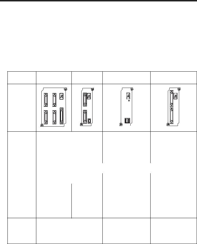
The following table lists the Motion Modules that can be used with the MP920.
Description |
SVA-01A |
SVA-02A |
SVB-01 |
PO-01 |
|
|
|
|
|
Model Number |
JEPMC-MC200A |
JEPMC-MC220A |
JEPMC-MC210 |
JEPMC-PL210 |
Appearance |
SVA-01 |
|
SVA-02 |
SVB-01 |
PO-01 |
|
|
||||
|
|
|
CN1 STATUS |
|
CN1 |
CN1 |
CN3 |
STATUS |
STATUS |
STATUS |
|
|
|
|
|
TRX |
|
|
|
CN5 |
|
|
|
CN2 |
CN4 |
|
CN2 |
|
CN2 |
|
|
|
|||
|
|
|
CN3 |
CN1 |
|
|
|
|
+24V |
|
|
|
|
|
0V |
|
|
Interface |
Analog |
|
MECHATROLINK |
Pulse |
|
|
|
|
|
|
|
Number of Con- |
4 |
|
2 |
14 |
4 |
trolled Axes per |
|
|
|
|
|
Module |
|
|
|
|
|
|
|
|
|
|
|
Maximum Num- |
15 |
|
16 |
16 |
16 |
ber of Modules |
|
|
|
|
|
|
|
|
|
|
|
Total Number of |
|
|
|
16 max. |
|
Modules |
|
|
|
|
|
|
|
|
|
||
Pulse Counting |
A/B, Up/Down, sign, ×1/2/4 |
×4 |
− |
||
Methods |
|
|
|
|
|
|
|
|
|
|
|
Control |
• Speed reference |
• Speed reference |
• Position control only |
• Position control only |
|
Functions |
output |
output |
Position loop is performed |
Open loop control |
|
|
• Synchronized phase |
• Synchronized |
by Servo Drivers. The SVB- |
The PO-01 Module outputs |
|
|
control |
phase control |
01 Module outputs position |
reference pulses. |
|
|
• Position control |
• Position control |
reference values. |
|
|
|
|
|
|||
•Torque reference output
Motion |
• Positioning |
• Positioning |
• Positioning |
Functions |
• Linear interpolation |
• Linear interpolation |
• Linear interpolation |
|
• Circular interpolation |
• Circular interpolation |
• Circular interpolation |
|
• Helical interpolation |
• Helical interpolation |
• Helical interpolation |
|
• External positioning |
• External positioning |
|
1-2
1.1 Module Overview and Features
|
|
|
|
(cont’d) |
||
|
|
|
|
|
|
|
Description |
SVA-01A |
SVA-02A |
SVB-01 |
PO-01 |
|
|
|
|
|
|
|
|
|
Model Number |
JEPMC-MC200A |
JEPMC-MC220A |
JEPMC-MC210 |
JEPMC-PL210 |
|
|
|
|
|
|
|
|
|
Applicable Ser- |
• Servo Drivers |
|
• Servo Drivers |
Pulse Motor Drivers |
|
|
vo Drivers and |
SGDA- S |
|
SGD- N |
|
|
|
Inverters |
SGDB- |
|
SGDBAN |
|
|
|
|
SGDM- |
|
SGDH- E+JUSP- |
|
|
|
|
SGDS- |
|
NS100 |
|
|
|
|
|
|
|
1 |
||
|
• Inverters |
|
• Inverters |
|
|
|
|
|
|
(216IF Card required) |
|
|
|
|
|
|
VS-616G5 |
|
|
|
|
|
|
|
|
|
|
|
|
|
VS-676H5 |
|
|
|
|
|
|
VS-676H5T |
|
|
|
|
|
|
|
|
|
|
Features |
Analog control |
|
High-speed network control |
Low-cost and simple control |
|
|
|
|
|
• Transmission speed: |
|
|
|
|
|
|
4 Mbps |
|
|
|
|
|
|
• Communications cycle: 2 ms |
|
|
|
|
|
|
• Transmission distance: 50 m |
|
|
|
|
|
|
max. |
|
|
|
|
|
|
Multi-axis control: |
|
|
|
|
|
|
14 axes max. per Module |
|
|
|
|
|
|
|
|
|
|
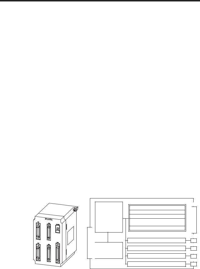
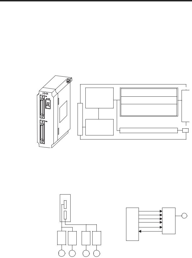
1.1.2SVA-01A Module
Overview of the SVA-01A Module
The SVA-01A Module is a Motion Control Module with analog outputs. One SVA-01A Module can control servos for up to four axes. Four connectors (CN1 to CN4) are provided for connections to SERVOPACKs. Each connector is equipped with a speed reference analog output, phase-A/B/C pulse inputs (5 V differential), a pulse latch digital input, and gen- eral-purpose digital I/O signals. The CN5 connector is equipped with positive and negative overtravel signals, deceleration limit inputs, zero point latch inputs, external positioning latch inputs, brake control outputs, and other external I/O signals for four axes.
System Bus Connector
Motion Control
Speed control
Position control
Phase control
Zero point return
function Monitor function
System Bus
Interface
Servo parameters OW
IW
Analog output: Speed ref. NREF
Pulse input: Phase A/B/C
General-purpose digital inputs (3) DI0 to D12
General-purpose digital outputs (5) DO0 to DO2 DO4, DO5
Sensor ON output (5 V/24 V) SENS/DO3
Same as above.
Same as above.
Same as above.
External (Field) I/O signals
CN1  ConnectorServo CN2
CN3
CN4
CN5
1-3
1 Overview of Motion Modules
1.1.3 SVA-02A Module
Features of the SVA-01A Module
•Analog-output 4-axis Servo Module
•Independent position control, speed reference output, torque reference output, and phase control are possible for each axis.
•Up to 60 axes (up to 15 Modules) can be controlled.
•Interpolations and complex processing operations can be easily programmed in motion programs.
|
|
15 Modules max. |
Speed, Position, and Phase Control |
|||||
|
|
|
Inverters |
|||||
|
|
|
|
|
|
|
||
SVA-01A |
Analog servos |
SVA-01A |
Speed |
SERVO- |
|
|||
|
|
|
SGDA |
D/A |
reference |
PACK |
M |
|
|
|
|
SGDB |
|
|
|||
|
|
|
|
|
|
|||
|
|
|
|
|
|
|
||
|
|
|
SGDM |
|
|
|
|
|
|
|
|
SGDS |
|
|
|
PG |
|
|
|
|
|
|
|
|
||
|
|
|
|
|
|
Encoder |
|
|
|
|
|
|
|
Counter |
pulse |
|
|
|
|
|
|
|
|
|
|
|
M |
M |
|
M |
M |
|
|
|
|
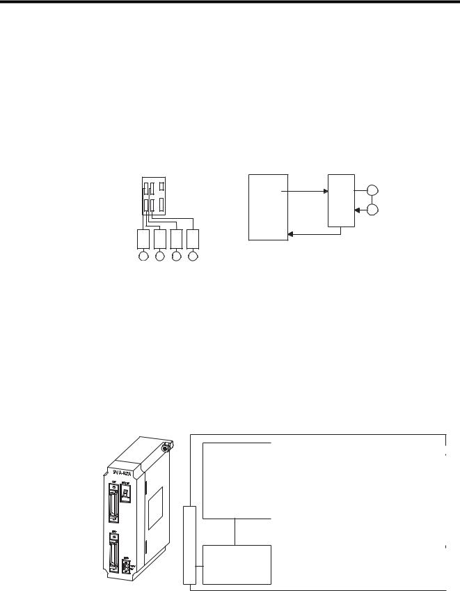
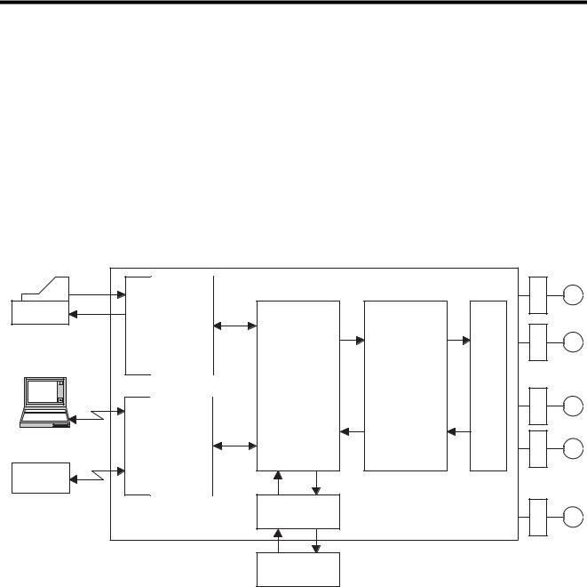
1.1.3SVA-02A Module
Overview of the SVA-02A Module
The SVA-02A Module is a Motion Control Module with analog outputs. One SVA-02A Module can control servos for up to two axes. Two connectors (CN1 and CN2) are provided for connections to SERVOPACKs and external I/O devices. Each connector is equipped with a speed reference analog output, a torque reference output, a torque monitoring analog output, phase A/B/C pulse inputs (5 V differential), a pulse latch digital input, and generalpurpose digital I/O signals.
System Bus Connector
Servo Control
Speed control
Position control
Torque control
Phase control
Zero point return
function Monitor function
System Bus
Interface
Servo parameters OW
IW
|
|
|
|
|
|
|
|
|
|
|
|
|
|
|
|
|
|
Analog outputs: Speed ref. |
NREF |
|
|
|
CN1 |
|
|||
|
|
|
|
Positive torque ref. TLIMP |
|
|
|
|
|
|
|
||
|
|
|
|
|
|
|
Connector |
|
|||||
|
|
|
|
Analog input: Speed monitor |
NREF |
|
|
|
|
|
|||
|
|
|
|
|
|
|
|
|
|
|
|||
|
|
|
|
Pulse input: Phase A/B/C |
|
|
|
|
|
|
|
|
|
|
|
|
|
|
|
|
|
|
|
|
|
|
|
|
|
|
|
Pulse latch digital input |
PIL |
|
|
|
|
|
|
|
|
|
|
|
|
General-purpose digital outputs (6) |
DO0 to DO2 |
|
|
|
|
Servo |
|
||
|
|
|
|
General-purpose digital inputs (5)+PI |
DI0 to DI5 |
|
|
|
|
|
|
|
|
|
|
|
|
|
DO4, DO5 |
|
|
|
|
|
|
|
|
|
|
|
|
|
|
|
|
|
|
|
|
||
|
|
|
|
|
|
|
|
|
|
|
|
||
|
|
|
|
|
|
|
|
|
|
|
|
|
|
|
|
|
|
Sensor ON output (5 V/24 V) |
SENS/DO3 |
|
|
|
|
|
|
|
|
|
|
|
|
|
|
|
|
|
CN2 |
|
|||
|
|
|
|
|
|
|
|
|
|||||
|
|
|
|
|
|
|
|
|
|
|
|
|
|
|
|
|
|
Same as above. |
|
|
|
|
|
|
|
|
|
|
|
|
|
|
|
|
|
|
|
|
|
|
|
1-4
1.1 Module Overview and Features
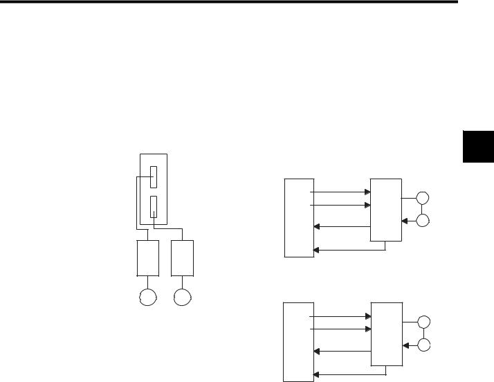
Features of the SVA-02A Module
• Analog-output 2-axis Servo Module
• Independent position control, speed reference output, torque reference output, and phase control are possible for each axis.
• Up to 32 axes (up to 16 Modules) can be controlled.
• Interpolations and complex processing operations can be easily programmed in motion
programs.
1
SVA-02A
|
16 Modules max. |
Speed, Position, and Phase Control |
||
|
Inverters |
SVA-02A |
|
|
|
Analog servos |
Speed reference |
SERVOPACK |
|
|
SGDA |
D/A |
|
M |
|
|
Torque control |
||
|
SGDB |
D/A |
|
|
|
|
|
||
|
SGDM |
|
|
|
|
SGDS |
A/D |
Speed monitor |
PG |
|
|
|||
|
|
|
|
|
|
|
Counter |
Encoder pulse |
|
|
|
|
|
|
M |
M |
|
Torque Control |
|
|
|
|
||
|
|
SVA-02A |
Torque reference |
SERVOPACK |
|
|
D/A |
|
|
|
|
|
M |
|
|
|
|
Speed control |
|
|
|
D/A |
|
|
|
|
|
|
|
|
|
A/D |
Torque monitor |
PG |
|
|
|
|
|
|
|
Counter |
Encoder pulse |
|
|
|
|
|
|
1-5
1 Overview of Motion Modules
1.1.4SVB-01 Module
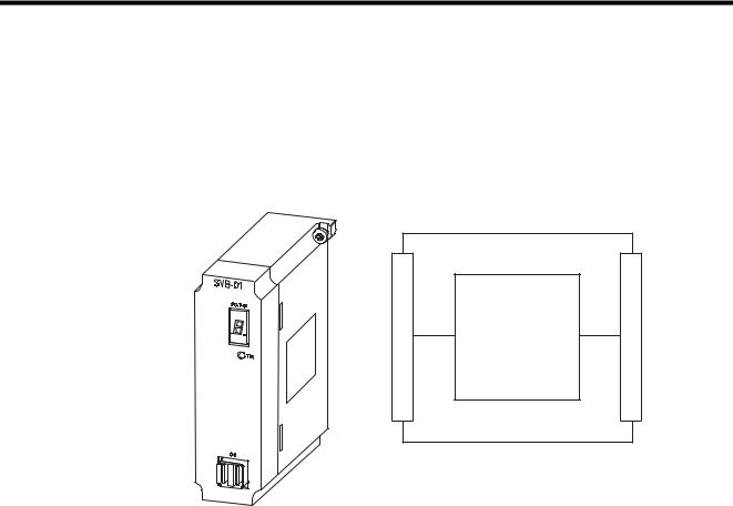
1.1.4SVB-01 Module
Overview of the SVB-01 Module
The SVB-01 Module has a single MECHATROLINK connector and can control up to 14
Module Devices with MECHATROLINK interfaces.
System Bus Connector
MECHATROLINK
Control
Servo Control
Remote I/O Control
Inverter Control
CN1
MECHATROLINK Connector
The SVB-01 Module can be connected to I/O Modules (such as the JEPMC-IO350) or Inverters (such as the VS-616G5 or VS-675H5) to transmit control signals and messages.
1-6
1.1 Module Overview and Features
Features of the SVB-01 Module
•By using the MECHATROLINK high-speed field network interface, up to 14 axes can be controlled with less wiring. A total of 224 axes can be controlled using a maximum of 16 Modules.
•Using the position control functions, motion programs can perform positioning, zero point returns, and interpolations.
|
|
|
|
|
|
|
|
|
|
|
1 |
|
|
SVB |
16 Modules max. |
||||||||
|
|
|
|||||||||
|
|
|
|
|
|
|
|
|
|
|
|
|
|
|
|
|
|
|
|
|
|
|
|
|
|
|
|
|
|
|
|
|
|
|
|
|
|
|
|
|
|
|
|
|
|
|
|
14 stations max.
M M M M
SGD-N or SGDB-N (connecting MECHATROLINKcompatible servos)
|
|
YASKAWA |
|
|||
|
|
JEPMC-IO350 |
|
|||
CN1 |
IN1 |
OUT1 |
|
|
IN2 |
OUT2 |
|
A1 |
B1 A1 |
B1 |
A1 |
B1 A1 |
B1 |
SW1
IN2
SW2 IN1
OUT2
OUT1
DC24V
DC 0V
616G5 |
RIO
1-7
1 Overview of Motion Modules
1.1.5PO-01 Module
1.1.5PO-01 Module
Overview of the PO-01 Module
The PO-01 Module is a Motion Control Module with pulse-train outputs. One PO-01 Module can be connected to pulse motor drivers for up to 4 axes.
Two connectors (CN1 and CN2) are provided for connections to pulse motor drivers. Each connector is equipped with a 5-V differential pulse-train output as well as 4 digital outputs (DO) and 5 digital inputs (DI) for various pulse driver control applications.
System Bus Connector
Motion functions Override function Stroke limit function Emergency stop function
System Bus
Interface
Servo Parameters
OW
IW
2 Pulse-train Outputs:CCW
CW
4 Digital Outputs: 1 Excitation ON
2 General-purpose
5 Digital Inputs: 1 Excitation monitor/zero point
3 General-purpose
1 Emergency/deceleration stop
Same as above.
CN1
DriverMotorConnector
Pulse
CN2
Features of the PO-01 Module
•The PO-01 Module can be connected to up to four axes.
•A total of 64 axes can be controlled using a maximum of 16 Modules.
•This Module provides positioning, zero point returns, interpolations, and other functions, all of which can be specified in motion programs.
PO-01
16 Modules max.
PO-01 |
CW+ |
Pulse |
|
|
CW- |
Motor |
M |
|
CCW+ |
Driver |
|
|
|
|
|
|
CCW- |
|
|
|
DO |
|
|
|
DI |
|
|
Pulse Motor
Driver
M M M M
1-8

1.2 System Configuration
1.2System Configuration
1.2.1System Configuration Examples
The MP920 Motion Modules are available with analog outputs, pulse outputs, and field network interfaces. Modules can be freely selected to configure the system best suited to the
application.
1
|
|
|
|
|
|
|
SVA-02A |
|
PO-01 |
|
|
|
|
||
PS-03 |
|
CPU-01 |
SVA-01A |
|
SVB-01 |
|
|
|
|
|
|||||
PS-03 |
|
MP920 CPU-01 |
|
SVA-01A |
|
SVA-02A |
SVB-01 |
PO-01 |
|
LIO-01 |
LIO-01 |
|
|
||
DC24V |
|
|
|
|
|
|
|
|
|
|
|
|
|
|
|
POWER |
SW1 |
|
|
|
|
|
|
|
CN1 |
|
CN1 |
CN1 |
|
|
|
|
1 |
|
|
RDY |
CN3 |
|
CN1 |
STATUS |
STATUS |
STATUS |
RUN |
RUN |
|
|
|
|
L.RST |
BATTERY |
CN1 |
STATUS |
|
|
|
|
|
||||||
|
2 |
RUN |
|
RUN |
|
|
|
|
|
|
|
FUSE |
FUSE |
|
|
|
3 |
INIT |
|
|
|
|
|
|
|
|
|
|
|
|
|
|
4 |
TEST |
|
ALM |
|
|
|
|
|
|
|
|
|
|
|
|
5 |
|
|
|
|
|
|
|
|
|
|
|
|
|
|
|
6 |
MULTI |
|
ERR |
|
|
|
|
|
|
|
|
|
|
|
|
7 |
FLASH |
|
|
|
|
|
|
|
|
|
|
|
|
|
|
8 |
M.RST |
|
BAT |
|
|
|
|
|
|
|
|
|
|
|
|
|
|
|
ALM |
|
|
|
|
|
|
|
|
|
|
|
|
ON |
OFF |
|
PRT2 |
|
|
|
|
|
|
|
|
|
|
|
|
PORT2 |
|
|
|
|
|
|
TRX |
|
|
|
|
|
|
|
|
|
|
|
PRT1 |
|
|
|
|
|
|
|
|
|
|
|
TB1 |
|
|
|
|
|
CN5 |
|
|
|
|
|
|
|
|
|
|
|
|
|
|
|
|
|
|
|
CN2 |
|
CN2 |
CN2 |
|
|
|
|
|
|
|
|
|
|
|
|
|
|
|
|
|
|
|
|
|
|
CN2 |
CN4 |
|
CN2 |
|
|
|
|
|
|
|
|
+24V |
|
|
|
|
|
|
|
|
|
|
|
|
|
|
|
|
PORT1 |
|
|
|
|
|
|
|
|
|
|
|
|
|
|
0V |
|
|
|
|
|
|
|
|
|
|
|
|
|
|
|
FG |
|
|
|
|
|
|
|
|
CN1 |
|
|
|
|
|
|
|
|
|
CN1 |
|
|
|
|
CN3 |
|
|
|
|
|
|
|
SG |
|
|
|
|
|
|
|
+24V |
|
|
|
|
|
|
|
|
|
|
RLY OUT |
|
|
|
|
|
|
|
|
|
|
|
|
|
|
|
|
|
|
|
|
0V |
|
|
|
|
|
|
|
Analog outputs for 4 axes |
|
|
|
|
|
|
|
|
|
Pulse outputs for 4 axes |
|||||
|
|
|
|
|
|
|
|
|
|
|
|
|
Pulse Motor Driver |
|
|
M |
M |
|
M |
M |
|
|
|
|
|
|
|
M |
M |
M |
M |
|
Analog output for 2 axes |
|
|
|
|
|
|
MECHATROLINK communications |
|||||||
|
|
|
|
|
|
|
|
|
|
|
MECHATROLINK-compatible servos |
||||
|
|
|
|
|
|
|
|
|
|
|
M |
|
M |
M |
M |
|
|
|
M |
M |
|
|
|
|
|
|
IO-350 |
|
216IF Inverter |
||
|
|
|
|
|
|
|
|
|
|
|
|
||||
Two analog outputs per axis One analog input per axis
|
|
YASKAWA |
|
|
||
|
|
JEPMC-IO350 |
|
|
||
|
CN1 |
IN1 |
OUT1 |
IN2 |
|
OUT2 |
|
A1 |
B1 A1 |
|
B1 A1 |
B1 A1 |
B1 |
SW1 |
|
|
|
|
|
|
|
IN2 |
|
|
|
|
|
SW2 |
IN1 |
|
|
|
|
|
|
OUT2 |
|
|
|
|
|
|
OUT1 |
|
|
|
|
|
DC24V |
|
|
|
|
|
|
DC 0V |
|
|
|
|
|
|
616G5 |
Up to 14 Modules can be connected.
1-9

1 Overview of Motion Modules
1.3.1General Specifications
1.3Specifications
This section gives an overview of the specifications and functions of the MP920 Modules.
1.3.1General Specifications
General Specifications of the MP920 Modules
Table 1.1 lists the general specifications of the MP920 Modules.
Table 1.1 General Specifications of the MP920 Modules
|
Item |
Specifications |
|
|
|
|
|
Environmental |
|
Ambient Operat- |
0 to 55°C |
Conditions |
|
ing Temperature |
|
|
|
|
|
|
|
Storage Tempera- |
-20 to 85°C |
|
|
ture |
|
|
|
|
|
|
|
Ambient Operat- |
30% to 95% RH (with no condensation) |
|
|
ing Humidity |
|
|
|
|
|
|
|
Ambient Storage |
5% to 95% RH (with no condensation) |
|
|
Humidity |
|
|
|
|
|
|
|
Pollution Level |
Pollution level 1 (conforming to JIS B 3501) |
|
|
|
|
|
|
Corrosive Gas |
There must be no combustible or corrosive gas. |
|
|
|
|
|
|
Operating |
2,000 m above sea level or lower |
|
|
Altitude |
|
|
|
|
|
Electrical |
|
Noise Resistance |
Conforming to JIS B 3502: |
Operating |
|
|
1,500 V (p-p) in either normal or common modes with a |
Conditions |
|
|
pulse width of 100 ns/11μs and a rise time of 1 ns (tested |
|
|
|
with impulse noise simulator) |
|
|
|
|
Mechanical |
|
Vibration |
Conforming to JIS B 3502: |
Operating |
|
Resistance |
10 to 57 Hz with single-amplitude of 0.075 mm |
Conditions |
|
|
57 to 150 Hz with fixed acceleration of 9.8 m/s2 (1G) |
|
|
|
10 sweeps each in X, Y, and Z directions |
|
|
|
(sweep time: 1 octave/min) |
|
|
|
|
|
|
Shock |
Conforming to JIS B 3502: |
|
|
Resistance |
Peak acceleration of 147 m/s2 (15G) twice for 11 ms each in |
|
|
|
the X, Y, and Z directions |
|
|
|
|
Installation |
|
Ground |
Ground to 100Ω max. |
Requirements |
|
|
|
|
Cooling Method |
Natural cooling |
|
|
|
||
|
|
|
|
1-10

1.3 Specifications
1.3.2Function Lists
Table 1.2 lists the motion control function specifications for the MP920.
|
|
|
|
Table 1.2 |
MP920 Motion Control Function Specifications |
|
|
|
||||
|
|
|
|
|
|
|
|
|
|
|
||
|
|
Item |
|
|
|
Specification |
|
|
|
|||
|
|
|
|
|
|
|
|
|
|
|
||
Description |
|
|
|
|
SVA-01A |
|
SVA-02A |
SVB-01 |
PO-01 |
|
|
|
Model Number |
|
|
JEPMC-MC200A |
JEPMC-MC220A |
JEPMC-MC210 |
JEPMC-PL210 |
|
1 |
||||
|
|
|
|
|
|
|
|
|
|
|
||
Interface |
|
|
|
|
Analog |
|
Analog |
MECHATROLINK |
Pulse |
|
||
|
|
|
|
|
|
|
|
|
||||
Number of Controlled Axes per Module |
|
4 |
|
2 |
14 |
4 |
|
|
||||
|
|
|
|
|
|
|
|
|
||||
Maximum Number of Modules |
|
15 |
|
16 |
16 |
16 |
|
|
||||
|
|
|
|
|
|
|
|
|
|
|||
Control |
|
PTP Control |
|
Linear, rotary, infinite-length, and independent axes |
|
|
|
|||||
Specifi- |
|
|
|
|
|
|
|
|
|
|
|
|
|
Interpolation |
|
Up to 16 linear axes, 2 circular axes, and 3 helical axes |
|
|
|
||||||
cations |
|
|
|
|
|
|||||||
|
|
|
|
|
|
|
|
|
|
|
|
|
|
Speed Reference Output |
|
Yes |
|
Yes |
No |
No |
|
|
|||
|
|
|
|
|
|
|||||||
|
|
|
|
|
|
|
|
|
|
|
||
|
|
Torque Reference Output |
|
No |
|
Yes |
No |
No |
|
|
||
|
|
|
|
|
|
|
|
|
|
|
||
|
|
Phase Control |
|
Yes |
|
Yes |
No |
No |
|
|
||
|
|
|
|
|
|
|
|
|
|
|
||
|
|
Position |
Positioning |
|
Yes |
|
Yes |
Yes |
Yes |
|
|
|
|
|
Control |
|
|
|
|
|
|
|
|
|
|
|
|
|
External Positioning |
|
Yes |
|
Yes |
Yes |
No |
|
|
|
|
|
|
|
|
|
|
|
|||||
|
|
|
|
|
|
|
|
|
|
|
|
|
|
|
|
|
Zero Point Return |
|
Yes |
|
Yes |
Yes |
Yes |
|
|
|
|
|
|
|
|
|
|
|
|
|
|
|
|
|
|
|
Interpolation |
|
Yes |
|
Yes |
Yes |
Yes |
|
|
|
|
|
|
|
|
|
|
|
|
|
|
|
|
|
|
|
Interpolation with |
|
Yes |
|
Yes |
Yes |
No |
|
|
|
|
|
|
Position Detection |
|
|
|
|
|
|
|
|
|
|
|
|
|
|
|
|
|
|
|
|
|
|
|
|
|
Fixed-speed Feed |
|
Yes |
|
Yes |
Yes |
Yes |
|
|
|
|
|
|
|
|
|
|
|
|
|
|
|
|
|
|
|
Fixed-length Feed |
|
Yes |
|
Yes |
Yes |
Yes |
|
|
|
|
|
|
|
|
|
|
|
|
|
|
|
Reference Unit |
|
|
mm, inch, deg, pulse |
|
|
|
|
|
||||
|
|
|
|
|
|
|
||||||
Reference Unit Minimum Setting |
|
1, 0.1, 0.01, 0.001, 0.0001, 0.00001 |
|
|
|
|
||||||
|
|
|
|
|
|
|||||||
Maximum Programmable Value |
|
-2147483648 to +2147483647 (signed 32-bit value) |
|
|
|
|||||||
|
|
|
|
|
|
|
|
|||||
Speed Reference Unit |
|
|
mm/min, inch/min, deg/min, pulses/min |
|
|
|
|
|||||
|
|
|
|
|
|
|
||||||
Acceleration/Deceleration Type |
|
Linear, asymmetric, S-curve, exponential |
|
|
|
|
||||||
|
|
|
|
|
|
|
|
|||||
Override Function |
|
|
Positioning: 0.01% to 327.67% by axis |
|
|
|
|
|||||
|
|
|
|
|
|
Interpolation: 0.01% to 327.67% by group |
|
|
|
|||
|
|
|
|
|
|
|
|
|
||||
Coordinate System |
|
|
Rectangular coordinates |
|
|
|
|
|
||||
|
|
|
|
|
|
|
|
|
|
|
||
Zero |
|
DEC1 + Phase-C |
|
Yes |
|
Yes |
Yes |
No |
|
|
||
Point |
|
|
|
|
|
|
|
|
|
|
|
|
|
DEC2 + Phase-C |
|
Yes |
|
Yes |
No |
No |
|
|
|||
Return |
|
|
|
|
|
|||||||
|
|
|
|
|
|
|
|
|
|
|
|
|
|
DEC1 + LMT + C |
|
Yes |
|
Yes |
No |
No |
|
|
|||
|
|
|
|
|
|
|||||||
|
|
|
|
|
|
|
|
|
|
|
|
|
|
|
Phase-C |
|
|
Yes |
|
Yes |
Yes |
No |
|
|
|
|
|
|
|
|
|
|
|
|
|
|
||
|
|
DEC1 + ZERO |
|
Yes |
|
No |
Yes |
Yes |
|
|
||
|
|
|
|
|
|
|
|
|
|
|
||
|
|
DEC2 + ZERO |
|
Yes |
|
No |
No |
Yes |
|
|
||
|
|
|
|
|
|
|
|
|
|
|
||
|
|
DEC1 + LMT + ZERO |
|
Yes |
|
No |
No |
Yes |
|
|
||
|
|
|
|
|
|
|
|
|
|
|
|
|
|
|
ZERO |
|
|
Yes |
|
No |
Yes |
No |
|
|
|
|
|
|
|
|
|
|
|
|
|
|
||
Pro- |
|
Language |
|
|
Special motion language, ladder logic program |
|
|
|
||||
grams |
|
|
|
|
|
|
|
|
|
|
|
|
|
Number of Tasks |
|
Up to eight programs can be executed in parallel. |
|
|
|
||||||
|
|
|
|
|
|
|||||||
|
|
|
|
|
|
|
|
|
|
|||
|
|
Number of Programs |
|
Up to 256 |
|
|
|
|
|
|||
|
|
|
|
|
|
|
|
|
|
|||
|
|
Program Capacity |
|
80 Kbytes |
|
|
|
|
|
|||
|
|
|
|
|
|
|
|
|
|
|
|
|
1-11

1 Overview of Motion Modules
1.3.2 Function Lists
Table 1.2 MP920 Motion Control Function Specifications (cont’d)
Item |
|
Specification |
|
|
|
|
|
|
|
Description |
SVA-01A |
SVA-02A |
SVB-01 |
PO-01 |
|
|
|
|
|
Applicable SERVOPACKs and Inverters |
SERVOPACKs |
SERVOPACKs |
SERVOPACKs |
Pulse Motor |
|
• SGDA- S |
• SGDA- S |
• SGD- N |
Drivers |
|
• SGDB- |
• SGDB- |
• SGDBAN |
|
|
• SGDM- |
• SGDM- |
• SGDH- |
|
|
• SGDS- |
• SGDS- |
E+ |
|
|
Inverters |
Inverters |
JUSP-NS100 |
|
|
Inverters (216IF |
|
||
|
|
|
|
|
|
|
|
board required) |
|
|
|
|
• VS-616G5 |
|
|
|
|
• VS-676H5 |
|
|
|
|
• VS-676H5T |
|
|
|
|
|
|
Encoder |
Incremental or |
Incremental or |
Incremental or |
No |
|
absolute |
absolute |
absolute |
|
|
|
|
|
|
Note: Yes: Can be controlled, No: Cannot be controlled.
1-12

2
Motion Control
2
This chapter gives an overview of motion control and describes the motion commands.
2.1 Overview of Motion Control - - - - - - - - - - - - - - - - - - - - - - - - 2-2
2.1.1 |
Motion Control for the MP920 - - - - - - - - - - - - - - - - - - - - - - - - - - - - |
2-2 |
2.1.2 |
Motion Control Methods - - - - - - - - - - - - - - - - - - - - - - - - - - - - - - - - |
2-4 |
2.1.3 |
Examples of Motion Control Applications - - - - - - - - - - - - - - - - - - - - |
2-5 |
2.2 Control Modes - - - - - - - - - - - - - - - - - - - - - - - - - - - - - - - - - 2-7
2.2.1 Overview of Control Modes - - - - - - - - - - - - - - - - - - - - - - - - - - - - - - 2-7 2.2.2 Speed Reference Output Mode - - - - - - - - - - - - - - - - - - - - - - - - - - - 2-8 2.2.3 Torque Reference Output Mode - - - - - - - - - - - - - - - - - - - - - - - - - - 2-12 2.2.4 Phase Control Mode - - - - - - - - - - - - - - - - - - - - - - - - - - - - - - - - - - 2-15 2.2.5 Zero Point Return Mode - - - - - - - - - - - - - - - - - - - - - - - - - - - - - - - 2-22
2.3 Position Control - - - - - - - - - - - - - - - - - - - - - - - - - - - - - - - 2-26
2.3.1 |
Prerequisites for Position Control - - - - - - - - - - - - - - - - - - - - - - - - - |
2-26 |
2.3.2 |
Position Control Without Using Motion Commands - - - - - - - - - - - - |
2-41 |
2.4 Position Control Using Motion Commands - - - - - - - - - - - - 2-45
2.4.1 Overview of Motion Commands - - - - - - - - - - - - - - - - - - - - - - - - - - 2-45 2.4.2 Positioning (POSING) - - - - - - - - - - - - - - - - - - - - - - - - - - - - - - - - - 2-48 2.4.3 External Positioning (EX_POSING) - - - - - - - - - - - - - - - - - - - - - - - 2-51 2.4.4 Zero Point Return (ZRET) - - - - - - - - - - - - - - - - - - - - - - - - - - - - - - 2-55 2.4.5 Interpolation (INTERPOLATE, END_OF_INTERPOLATE) - - - - - - - 2-70 2.4.6 Interpolation with Position Detection (LATCH) - - - - - - - - - - - - - - - - 2-73 2.4.7 Fixed Speed Feed (FEED) - - - - - - - - - - - - - - - - - - - - - - - - - - - - - - 2-74 2.4.8 Fixed Length Feed (STEP) - - - - - - - - - - - - - - - - - - - - - - - - - - - - - 2-77 2.4.9 Zero Point Setting (ZSET) - - - - - - - - - - - - - - - - - - - - - - - - - - - - - - 2-81
2-1
2 Motion Control
2.1.1Motion Control for the MP920
2.1Overview of Motion Control
This section describes the methods used for motion control and gives some examples of their use.
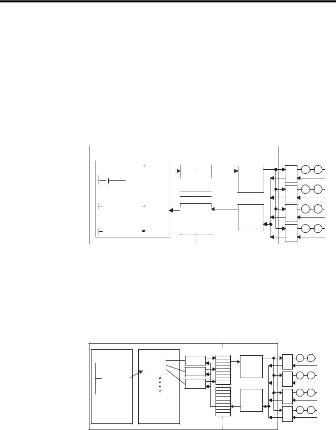
2.1.1Motion Control for the MP920
The MP920 Machine Controller provides fully integrated sequence control and motion control.
The following diagram shows a conceptual diagram of the MP920 system.
|
|
|
|
|
|
|
SERVOPACK |
|
|
|
|
Ladder logic program |
MC program |
|
M |
|
|
|
|
|
|
|
|
Operation |
Module |
processing |
|
|
|
|
|
panel |
|
|
|
|
|||
|
|
I/O |
Sequence |
Motion control |
|
|
|
|
|
|
|
|
|
||
|
I/O |
|
control |
|
|
M |
|
|
|
|
|
|
|||
|
|
|
|
Module |
|
||
|
|
|
|
|
|
Inverter |
|
|
Communications |
Module |
|
|
|
Motion |
|
|
|
|
|
M |
|||
|
|
|
|
|
|
|
|
Programming |
|
|
Commu- |
|
|
|
|
Device |
|
|
nications |
|
|
|
M |
|
|
|
control |
|
|
|
|
Other |
|
|
|
|
|
|
|
company's |
|
|
|
|
|
|
Pulse motor |
sequencer |
|
|
|
|
|
|
|
|
|
|
|
|
|
driver |
|
|
|
|
|
|
|
|
|
|
|
|
|
Analog Module |
|
|
M |
|
|
|
|
|
|
|
|
|
|
|
|
Analog Device |
|
|
|
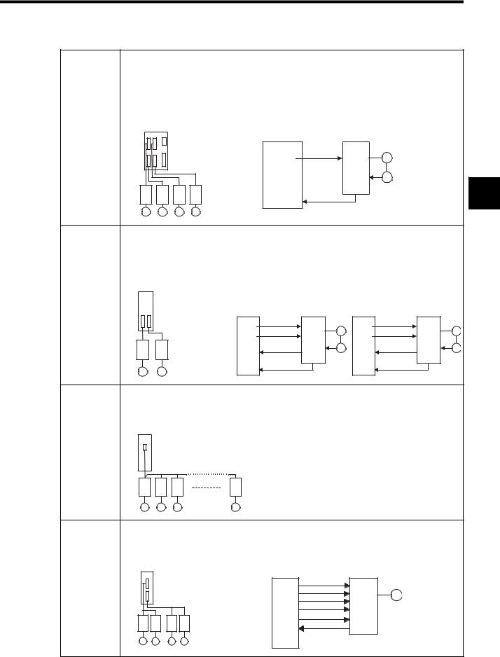
A wide range of Motion Modules is provided for the MP920, and these can be selected according to the purpose.
The following table shows the types of Motion Module and their features.
2-2
2.1 Overview of Motion Control
Name |
Features |
|
|
SVA-01A |
• Analog-output 4-axis Servo Module |
•Independent position control, speed control, and phase control are possible for each axis.
•Up to 60 axes (up to 15 Modules) can be controlled.
•Interpolations and complex processing operations can be easily programmed in motion programs.
|
15 Modules max. |
|
|
|
||
SVA-01A |
Inverters |
|
Speed, position, and phase control |
|||
|
Analog servos |
|
Speed |
|
||
|
SGDA- |
|
S |
SVA-01A |
SERVOPACK |
|
|
|
reference |
|
|||
|
SGDB |
|
|
|
M |
|
|
|
|
D/A |
|
||
|
SGDM |
|
|
|
|
|
|
|
|
|
|
|
|
|
|
|
|
|
|
PG |
|
|
|
|
|
Encoder |
2 |
|
|
|
|
Counter |
Pulse |
|
|
M M M M |
SVA-02A |
• Analog-output 2-axis Servo Module |
•Independent position control, speed control, torque, and phase control are possible for each axis.
•Up to 32 axes (up to 16 Modules) can be controlled.
•Interpolations and complex processing operations can be easily programmed in motion programs.
|
16 Modules max. |
|
|
|
|
|
|
||
SVA-02A |
Inverters |
|
|
|
|
|
|
|
|
|
Analog servos |
Speed, position, and phase control |
Torque control |
||||||
|
SGDA- |
|
S |
||||||
|
|
|
|
|
|
|
|
||
|
SGDB |
|
|
SVA-02A |
Speed reference |
SERVOPACK |
SVA-02A |
Torque reference |
SERVOPACK |
|
SGDM |
|
|
||||||
|
|
|
D/A |
M |
D/A |
M |
|||
|
|
|
|
|
Torque limit |
|
Speed limit |
||
|
|
|
|
D/A |
|
D/A |
|
||
|
|
|
|
|
|
|
|
||
|
|
|
|
A/D |
Speed monitor |
PG |
A/D |
Torque monitor |
PG |
|
|
|
|
|
|
|
|
||
|
|
|
|
Counter |
Encoder |
|
Counter |
Encoder |
|
M |
M |
|
|
Pulse |
|
Pulse |
|
||
|
|
|
|
|
|
||||
|
|
|
|
|
|
|
|
||
SVB-01 |
• By using the high-speed field network (MECHATROLINK) interface, up to 14 axes can be con- |
|
trolled with less wiring. (Using a maximum of 16 Modules, 224 axes can be controlled.) |
•Using the position control functions, motion programs can perform positioning, zero point returns, and interpolations.
|
SVB |
16 Modules max. |
|
|
|
|
|
|
|
14 axes max. |
|
|
|
|
SGD-N or |
|
|
|
SGDB-N |
|
M M M |
M |
|
PO-01 |
• Pulse output type 4-axis Pulse Output Module |
||
•Up to 64 axes (up to 16 Modules) can be controlled.
•Using the position control functions, motion programs can perform positioning, zero point returns, and interpolations.
PO-01 |
|
|
|
|
16 Modules max. |
PO-01 |
CW+ |
Pulse |
|
|
|
CW- |
motor |
M |
|
|
CCW+ |
driver |
|
|
|
|
||
|
|
CCW- |
|
|
Pulse motor driver |
|
DO |
|
|
|
DI |
|
|
|
|
|
|
|
|
M M M M |
|
|
|
|
2-3
2 Motion Control
2.1.2Motion Control Methods
2.1.2Motion Control Methods
By using Motion Modules, motions for a wide variety of applications can be controlled. There are two programming methods for controlling motions: Ladder logic programs and motion programs. An overview of each programming method is given below.
Ladder Logic Programming
Ladder logic programs are designed mainly for sequence control. The motion setting parameters and motion monitoring parameters used as interfaces with the Motion Modules are directly written to and read by the ladder logic programs to perform motion control.
|
|
|
|
CPU Module |
|
|
|
|
|
|
|
|
SVA Module |
|
||
|
|
|
Ladder logic program |
|
|
|
|
|
|
|
|
|
|
|
|
|
|
|
|
|
|
|
|
Setting Parameters |
|
|
|
||||||
|
|
|
H0101 |
OWC000 |
|
|
||||||||||
|
|
|
|
|
|
|
|
|
|
|
|
|
Motion |
|
||
|
|
B00105 |
|
|
|
|
|
|
|
|
|
|
|
|
||
|
|
|
|
|
|
|
|
|
|
|
|
|
|
|||
processing
IFON |
|
|
|
|
Monitoring Parameters |
500 |
OWC015 |
Status |
|
|
Status |
ELSE |
|
information |
0 |
OWC015 |
|
M |
PG |
SERVO- |
|
PACK |
|
M |
PG |
SERVO- |
|
PACK |
|
M |
PG |
SERVO- |
|
PACK |
|
M |
PG |
SERVO- |
|
PACK |
|
Special operations can be programmed and combined as user functions. For details, refer to Chapter4 Parameters and the section describing the parameters of each Motion Module.
Motion Programming
The motion programs that have been created using a special motion language perform motion control. Up to 256 programs can be created, and these can also be executed in parallel.
CPU Module
CPU Module |
Motion program |
MOV [X] 100
MVS [X] 100
MCC - - - -
EXT
MSEE MPM001
|
SVA Module |
|
|
|
|
Setting Parameters |
|
|
|
MOV |
|
SERVO- |
M |
PG |
command |
|
|
|
|
Command |
PACK |
|
|
|
|
|
|
||
MOV |
processing |
|
|
|
command |
|
|
M |
PG |
|
|
SERVO- |
||
|
|
|
|
|
MOV |
|
PACK |
|
|
|
|
|
|
|
command |
|
|
|
|
|
|
SERVO- |
M |
PG |
|
Status |
|
|
|
|
PACK |
|
|
|
|
information |
|
|
|
|
|
SERVO- |
M |
PG |
|
|
PACK |
|
|
Monitoring Parameters |
|
|
|
|
The use of the special motion language enables complex operations to be easily programmed. The system performs command end checks and other processing. The special motion commands shown in the following table are provided as standard in the MP9 Series.
2-4
Loading...