


 Loading...
SMC-2000 Multi-Axis Motion Controller
User’s Guide Version 3.1

Overview
Introduction
The SMC-2000 Series are packaged motion controllers designed for stand-alone operation. Features include coordinated motion profiling, uncommitted inputs and outputs, non-volatile memory for stand-alone operation and RS232/RS422 communication. Extended performance capability includes: fast 8 MHz encoder input frequency, precise 16-bit motor command output DAC, +/-2 billion counts total travel per move, faster sample rate, and multitasking of up to four programs. The controllers provide increased performance and flexibility featuring plug and play operation.
Designed for maximum system flexibility, the SMC-2000 is available in one, two, four, and eight axes configurations.
Each axis accepts feedback from a quadrature linear or rotary encoder with input frequencies up to 8 million quadrature counts per second. For dual-loop applications that require one encoder on both the motor and the load, auxiliary encoder inputs are included for each axis.
The powerful controller provides several modes of motion including jogging, point-to-point positioning, linear and circular interpolation with infinite vector feed, electronic gearing and user-defined path following. Several motion parameters can be specified including acceleration and deceleration rates, and slew speed. To eliminate jerk, the SMC-2000 provides S-curve profiling.
For synchronizing motion with external events, the SMC-2000 includes 8 optically isolated inputs, eight programmable outputs and seven analog inputs (eight optional). I/O expansion boards provide additional inputs and outputs. Event triggers can automatically check for elapsed time, distance and motion complete.
Despite its full range of sophisticated features, the SMC-2000 is easy to program. Instructions are represented by two letter commands such as BG for Begin and SP for Speed. Conditional Instructions, Jump Statements, and arithmetic functions are included for writing self-contained applications programs.
To prevent system damage during machine operation, the SMC-2000 provides several error handling features. These include software and hardware limits, automatic shut-off on excessive error, abort input, and user-definable error and limit routines.
SMC-2000 User's Guide |
Overview • 1 |
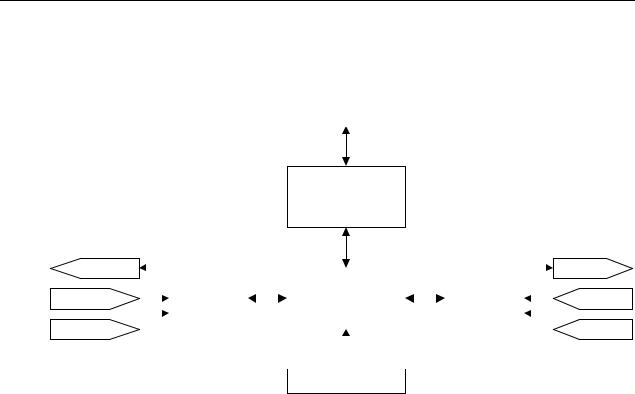
SMC-2000 Functional Elements
The SMC-2000 circuitry can be divided into the following functional groups as shown in Figure 1.1 and discussed below.
To Host
RS-232 / RS-422 Serial
Communication FIFO
80 Bytes
8 24V Out |
|
|
|
|
|
|
|
|
|
|
|
|
|
|
|
|
|
To Amps |
|
|
|
|
|
|
|
|
68340 |
|
|
|
4-Axes |
|
|||||||
|
|
|
|
|
|
|
|
|
|
|
|
|
|
|
|
|
|||
|
|
|
|
|
|
|
|
|
Microcomputer |
|
|
|
|
|
|
|
|
||
8 Digital In |
|
|
|
|
I/O |
|
|
|
|
|
|
Motor/Encoder |
|
|
|
|
From |
||
|
|
|
|
|
|
|
1024K RAM |
|
|
|
|
|
|
|
|||||
|
|
Interface |
|
|
|
|
|
|
Interface |
|
|
|
|
Limits |
|||||
|
|
|
|
|
|
|
|
|
|
|
|||||||||
|
|
|
|
|
|
|
|
256K EPROM |
|
|
|
|
|
|
|
||||
|
|
|
|
|
|
|
|
|
|
|
|
|
|
|
|
|
|
||
8 Analog In |
|
|
|
|
|
|
|
|
1024 EEPROM |
|
|
|
|
|
|
|
|
From |
|
|
|
|
|
|
|
|
|
|
|
|
|
|
|
|
|
|
|
||
|
|
|
|
|
|
|
|
|
|
|
|
|
|
|
|
Encoders |
|||
|
|
|
|
|
|
|
|
|
|
|
|
|
|
|
|
|
|
|
|
|
|
|
|
|
|
|
|
|
|
|
|
|
|
|
|||||
|
|
|
|
|
|
|
|
|
|
|
|
|
|
|
|
|
|
|
|
Watch Dog
Timer
Figure 1.1 - SMC-2000 Functional Elements
Microcomputer Section
The main processing unit of the SMC-2000 is a specialized 32-bit Motorola 68340 Series Microcomputer with 256K RAM, 64 K EPROM and 128 K bytes EEPROM. The RAM provides memory for variables, array elements, and application programs. The EPROM stores the firmware of the SMC-2000. The EEPROM allows parameters and programs to be saved in non-volatile memory upon power down.
Motor Interface
For each axis, a sub-micron gate array performs quadrature decoding of the encoders at up to 8 MHz, generates the +/-10 Volt analog signal (16-Bit D-to-A) for input to a servo amplifier. Interface to hardware limits and home inputs is also included.
Communication
Communication to the SMC-2000 is via two separately addressable RS232 ports. The factory may also configure the ports for RS422. The serial ports may be daisy-chained to other SMC-2000 controllers.
General I/O
The SMC-2000 provides interface circuitry for eight opto-isolated inputs, eight general outputs, and seven (or eight) analog inputs (14-Bit ADC). The eight axis SMC-2000 provides 24 inputs and 16 outputs. Additional I/O is optional.

System Elements
As shown in Fig. 1.2, the SMC-2000 is part of a motion control system that includes amplifiers, motors, and encoders. These elements are described below
Power Supply
|
|
|
|
|
|
|
|
Computer |
|
SMC-2000 Controller |
|
Driver |
|
||
|
|
|
|||||
|
|
|
|
|
|
|
|
|
|
|
|
|
|
|
|
Encoder |
Motor |
Figure 1.2 - Elements of Servo systems
Motor
A motor converts current into torque, which produces motion. Each axis of motion requires a motor sized properly to move the load at the required speed and acceleration. (Yaskawa's "YSize" software can help you with motor sizing).
The servo motor and can be brush-type or brushless, rotary or linear. Please refer to Yaskawa catalogs for more information.
Amplifier
For each axis, the power amplifier converts the +/-10 Volt signal from the controller into enough current to drive the motor. As such, the amplifier should be sized properly to meet the power requirements of the motor. For brushless motors, an amplifier that provides electronic commutation is required. The amplifier should be set up to operate in a torque control mode. Set the torque reference gain so that 10 Volts at the torque reference input will allow the amplifier/motor to operate at peak torque (typically 200-300% of rated torque). See Yaskawa technical manuals for specifications. Please call Yaskawa if you need help configuring your amplifier.
Encoder
An encoder translates motion into an electrical signal to be fed back into the controller. The SMC-2000 accepts feedback from either a rotary or linear encoder. The preferred encoder is the one with two channels in quadrature, CHA and CHB. This encoder may also have a third channel (or index) for synchronization. When necessary, the SMC-2000 can interface to encoders with pulse and direction signals.
There is no limit on encoder line density, however, the input frequency to the controller must not exceed 2,000,000 full encoder cycles/second (8,000,000 quadrature counts/sec). For example, if the encoder line density is 10000 cycles per inch, the maximum speed is 200 inches/second.
The encoder type may be either single-ended (CHA and CHB) or differential (CHA,CHA-,CHB,CHB-). The SMC-2000 decodes either type into quadrature states or four times the number of cycles.
SMC-2000 User's Guide |
Overview • 3 |
The standard voltage level is TTL (zero to five volts), however, voltage levels up to 12 Volts are acceptable. (If using differential signals, 12 Volts can be input directly to the SMC-2000. Single-ended 12 Volt signals require a bias voltage input to the complementary inputs)
SMC-2000 User's Guide |
Overview • 1 |

Getting Started
Elements You Need
Before you start, you must get all the necessary system elements. These include:
1.SMC-2000 Series Controller
2.Servo motors and amplifiers
3.24 Volt Class 2 Power Supply for SMC-2000 and Amplifiers
4.PC (Personal Computer with RS232 port) with at least 4MB of RAM and Windows 3.1 or higher.
5.Communication Disk (YTerm-2000 software) from Yaskawa
6.All interface and communication cables
Warning: Follow the “Tuning Servo System” procedure before applying power to the SMC unit and the servo amplifier at the same time. Applying power to the SMC unit and the amplifiers at the same time may result in damage to the mechanical system if the initial gain parameters for the SMC unit are not properly set.
Installing the SMC-2000
Connecting AC and DC Power to the Controller
The SMC-2000 requires a single AC supply voltage, single phase, 50 Hz or 60 Hz, from 85 volts to 264 volts, and a +24 (±10%) Volt Class 2 DC supply for I/O. It is also recommended that AC and DC wiring is kept separate in order to avoid noise and interference.
Warning: Do NOT use the I/O 24 VDC power supply to power any holding brakes that may be connected to your servo motors. Use a dedicated supply for that purpose.
Warning: Dangerous voltages, current, temperatures and energy levels exist in this product and in its associated amplifier(s) and servo motor(s). Extreme caution should be exercised in the application of this equipment. Only qualified individuals should attempt to install, set up and operate this equipment.
SMC-2000 User's Guide |
Getting Started • 1 |

The AC and DC power is applied to the power connector at the bottom of the front panel. The power connector is a 6-pin black screw-type terminal. Note that the AC power is applied to the LEFT side while the DC power is applied to the RIGHT. The five connections are:
Pin |
Connect to: |
|
|
GND |
Earth Ground |
|
|
N & L |
AC In, 85V - 264V |
|
|
0 & 24V |
24 Volt DC and Common |
|
|
|
|
Warning: Never open the controller box when AC power is applied to it.
Applying AC power will turn on the green light power indicator.
Connecting Servo Motors and the Amplifiers
Before connecting the amplifier to the controller, you need to verify that the ground level of the amplifier is either floating or at the same potential as earth.
WARNING: When the amplifier ground is not isolated from the power line or when it has a different potential than that of the computer ground serious damage will result to the computer controller and amplifier.
If you are not sure about the potential of the ground levels, connect the two ground signals by a 10 KΩ resistor and measure the voltage across the resistor. Only if the voltage is zero, proceed to connect the two ground signals directly.
Establishing Communication - RS232
Use the 9-Pin RS232 cable to connect the MAIN (Com 1) SMC-2000 serial port to your computer Com port. Your computer must be configured for a baud rate setting of 19.2 KB, full duplex, no parity, 8 bits data, one start bit, and one stop bit. The Yaskawa software “YTerm-2000” will accomplish this configuration.
At this point you should install YTerm-2000 software. This software requires the use of Windows 3.1 or above, and at least 4M of RAM. The YTerm-2000 communication disk from Yaskawa provides a terminal emulator / configuration program for your computer. Follow the steps below to install and run the terminal emulator.
Installation:
1.Insert Disk in drive A: ( or B)
2.From Windows Program Manager or Start Menu, select <Run> command.
3.Run: A:\Setup ( or B:\Setup)
4.After the Yaskawa group is created, make sure the SMC-2000 has AC power connected to it then double-click the YTerm-2000 icon to start the program.
Encoder Interface
Encoder interface is part of the Yaskawa supplied cable that connects the SMC with the Yaskawa amplifier. See the pinout for connector AE1 or AE2 for Auxiliary Encoder interface connection, found in the appendix.
2 •Getting Started |
SMC-2000 User's Guide |

Tuning Servo System
Step 1. Setting servo(s) parameters
Yaskawa servo amplifier models SGD, SGDA, SGDB need to be set up to operate in a Torque Mode.
Parameter ( SGD, SGDA ) |
Function |
Setting |
|
|
|
Cn-01, bit B , A |
Torque Control Mode Selection |
1,0 |
|
|
|
Cn-13 |
Torque Reference Gain |
30 |
|
|
|
Cn-01, bit 2,3 |
Limit Switch Disable |
1,1 |
|
|
|
|
|
|
Parameter ( SGDB ) |
Function |
Setting |
|
|
|
Cn-2B |
Torque Control Mode Selection |
2 |
|
|
|
Cn-13 |
Torque Reference Gain |
30 |
|
|
|
Cn-01, bit 2,3 |
Limit Switch Disable |
1,1 |
|
|
|
|
|
|
NOTE: When using a motor with an absolute encoder please see the Absolute Encoder section in chapter 12 for additional parameter settings.
Step 2. Applying Power to SMC unit and servos
Apply power to SMC-2000. Input the command MO (CR), this will shut off control of the SMC to the servo(s). Apply power to the servo amplifier.
Step 3. Setting Gain values in SMC unit
Set gains to default values:
Command |
Function |
Default value for |
|
|
SG** servo |
|
|
|
KD |
Derivative Constant |
10 |
|
|
|
KP |
Proportional Constant |
1 |
|
|
|
KI |
Integrator |
0 |
|
|
|
|
|
|
Step 4. Enable Servo
In order to properly tune the servo system, enable one servo at a time with the SH* command ( *=X, Y, Z, W, E, F, G, H). After enabling a servo, maximize the gains.
Step 5. Maximize Gains
For more damping, you can increase KD (maximum is 4095). Increase gradually and stop after the motor vibrates. A vibration is noticed by the audible sound or by interrogation. If you send the command
TE X (CR) |
Tell error |
SMC-2000 User's Guide |
Getting Started • 3 |

a few times, and get varying responses, especially with reversing polarity, it indicates system vibration. When that is the case, simply reduce KD.
Next you need to increase the value of KP gradually (maximum allowed is 1023). You can monitor the improvement in the response with the Tell Error instruction.
KP 10 (CR) |
Proportion gain |
TE X (CR) |
Tell error |
As the proportional gain is increased, the error decreases.
Here again, the system may vibrate if the gain is too high. When that is the case, reduce KP. Typically, KP should not be greater than KD/4.
Finally, increase the value of KI, start with zero value and increase it gradually. The integrator eliminates the position error, resulting in improved accuracy. Therefore, the response to the instruction
TE X (CR)
becomes zero. As KI is increased, its effect is amplified and it may lead to vibrations. When that occurs, simply reduce KI.
After tuning one axis, disable the servo with the MO* command ( *=X, Y, Z, W, E, F, G, H), and repeat the tuning process for the remaining axes.
After each servo has been properly tuned, the values now need to be burned into the EEROM. This is done by issuing the BN command. After the BN command has been issued the new values will remain effective.
Next, you are ready to try a few motion examples.
Motion Examples
Here are a few examples for using your controller.
Example 1- Profiled Move
Objective: Rotate the X-axis a distance of 10,000 counts at a slew speed of 20,000 counts/sec and an acceleration and deceleration rates of 100,000 counts/s2.
Instruction |
Interpretation |
|
|
PR 10000 |
Distance |
|
|
SP 20000 |
Speed |
|
|
DC 100000 |
Deceleration |
|
|
AC 100000 |
Acceleration |
|
|
BG X |
Start Motion |
|
|
|
|
In response, the motor turns and stops.
Example 2 - Multiple Axes
Objective: To move four axes independently.
4 •Getting Started |
SMC-2000 User's Guide |
Instruction |
Interpretation |
|
|
PR 500,1000,600,-400 |
Distances of X,Y,Z,W |
|
|
SP 10000,12000,20000,10000 |
Slew speeds of X,Y,Z,W |
|
|
AC 100000,10000,100000,100000 |
Accelerations of X,Y,Z,W |
|
|
DC 80000,40000,30000,50000 |
Decelerations of X,Y,Z,W |
|
|
BG XZ |
Start X and Z motion |
|
|
BG YW |
Start Y and W motion |
|
|
|
|
Example 3 - Independent Moves
The motion parameters may be specified independently as illustrated below.
Instruction |
Interpretation |
|
|
PR ,300,-600 |
Distances of Y and Z |
|
|
SP ,2000 |
Slew speed of Y |
|
|
DC,80000 |
Deceleration of Y |
|
|
AC,100000 |
Acceleration of Y |
|
|
SP ,,40000 |
Slew speed of Z |
|
|
AC ,,100000 |
Acceleration of Z |
|
|
DC ,,150000 |
Deceleration of Z |
|
|
BG Z |
Start Z motion |
|
|
BG Y |
Start Y motion |
|
|
|
|
Example 4 - Position Interrogation
The position of all axes may be interrogated with the instruction
TP |
Tell position all axes |
|
|
|
|
which returns all of the positions of the motors separated by commas. Individual axis may be interrogated with the instructions:
TP X |
Tell position - X axis only |
|
|
TP Y |
Tell position - Y axis only |
|
|
TP Z |
Tell position - Z axis only |
|
|
TP W |
Tell position - W axis only |
|
|
TP E |
Tell position - E axis only (SMC-2000-8 only) |
|
|
TP F |
Tell position - F axis only (SMC-2000-8 only) |
|
|
TP G |
Tell position - G axis only (SMC-2000-8 only) |
|
|
TP H |
Tell position - H axis only (SMC-2000-8 only) |
|
|
|
|
The position error, which is the difference between the commanded position and the actual position, can be interrogated by the instructions
SMC-2000 User's Guide |
Getting Started • 5 |
TE |
Tell error - all axes |
|
|
TE X |
Tell error - X axis only |
|
|
TE Y |
Tell error - Y axis only |
|
|
TE Z |
Tell error - Z axis only |
|
|
TE W |
Tell error - W axis only |
|
|
|
|
Example 5- Absolute Position
Objective: Command motion by specifying the absolute position.
Instruction |
Interpretation |
|
|
DP 0,2000 |
Define the current positions of X,Y as 0 and 2000 |
|
|
PA 7000,4000 |
Sets the desired absolute positions |
|
|
BG X |
Start X motion |
|
|
BG Y |
Start Y motion |
|
|
|
|
After both motions are completed, command: |
|
PA 0,0 |
Move to 0,0 |
|
|
BG XY |
Start both motions |
|
|
|
|
Example 6 - Velocity Control
Objective: Drive the X and Y motors at specified speeds.
Instruction |
Interpretation |
|
|
JG 10000,-20000 |
Set Jog Speeds and Directions |
|
|
AC 100000, 40000 |
Set accelerations |
|
|
DC 50000,50000 |
Set decelerations |
|
|
BG XY |
Start motion |
|
|
|
|
after a few seconds, command: |
|
JG -40000 |
New X speed and Direction |
|
|
TV X |
Returns X speed |
|
|
|
|
and then |
|
JG ,20000 |
New Y speed |
|
|
TV Y |
Returns Y speed |
|
|
|
|
These cause velocity changes, including direction reversal. The motion can be stopped with the instruction
ST |
Stop |
|
|
|
|
6 •Getting Started |
SMC-2000 User's Guide |
Example 7 - Operation under Torque Limit
The magnitude of the motor command may be limited independently by the instruction TL. The following program illustrates that effect.
Instruction |
Interpretation |
|
|
TL 0.2 |
Set output limit of X axis to 0.2 volts |
|
|
JG 10000 |
Set X speed |
|
|
BG X |
Start X motion |
|
|
|
|
The X motor will probably not move as the output signal is not sufficient to overcome the friction. If the motion starts, it can be stopped easily by the touch of a finger.
Increase the torque level gradually by instructions such as
TL 1.0 |
Increase torque limit to 1 volt. |
|
|
TL 9.998 |
Increase torque limit to maximum, 9.998 Volts. |
|
|
|
|
The maximum level of 10 volts provides the full output torque.
Example 8 - Interrogation
The values of the parameters may be interrogated. For example, the instruction
KP ? |
Return gain of X-axis. |
|
|
|
|
returns the value of the proportional gain of the X axis. Similarly, the instruction
KP ,,? |
Return gain of Z-axis. |
|
|
|
|
returns the value of the Z axis gain.
KP ?,?,?,? |
Return gains of all axes. |
|
|
|
|
returns the gain values for the four axes.
The same procedure applies to other parameters such as KI, KD, FA, etc.
Example 9 - Operation in the Buffer Mode
The instructions may be buffered before execution as shown below.
PR 600000 |
Distance |
|
|
SP 10000 |
Speed |
|
|
WT 10000 |
Wait 10000 milliseconds before reading the next |
|
instruction |
BG X |
Start the motion |
|
|
|
|
SMC-2000 User's Guide |
Getting Started • 7 |
Example 10 - Motion Programs
Motion programs may be edited and stored in memory using Yaskawa’s YTerm-2000 software. They may be executed at a later time.
#A |
Define label |
|
|
PR 700 |
Distance |
|
|
SP 2000 |
Speed |
|
|
BGX |
Start X motion |
|
|
EN |
End program |
|
|
|
|
Now the program may be executed with the command
XQ #A |
Start the program running |
|
|
|
|
Example 11 - Motion Programs with Loops
Motion programs may include conditional jumps as shown below.
Instruction |
Interpretation |
|
|
#A |
Label |
|
|
DP 0 |
Define current position as zero |
|
|
V1=1000 |
Set initial value of V1 |
|
|
#LOOP |
Label for loop |
|
|
PA V1 |
Move X motor V1 counts |
|
|
BG X |
Start X motion |
|
|
AM X |
After X motion is complete |
|
|
WT 500 |
Wait 500 ms |
|
|
TP X |
Tell position X |
|
|
V1=V1+1000 |
Increase the value of V1 |
|
|
JP #LOOP,V1<10001 |
Repeat if V1<10001 |
|
|
EN |
End |
|
|
|
|
After the above program is entered and downloaded to the SMC-2000, use the following command to run the program:
XQ #A |
Execute Program #A |
|
|
|
|
Example 12 - Motion Programs with Trippoints
The motion programs may include trippoints as shown below.
|
Instruction |
Interpretation |
|
|
|
|
#B |
Label |
|
|
|
|
DP 0,0 |
Define initial positions |
|
|
|
|
PR 30000,60000 |
Set targets |
|
|
|
|
SP 5000,5000 |
Set speeds |
|
|
|
|
|
|
|
|
|
8 •Getting Started |
SMC-2000 User's Guide |
|
BGX |
Start X motion |
|
|
AD 4000 |
Wait until X moved 4000 |
|
|
BGY |
Start Y motion |
|
|
AP 6000 |
Wait until position X=6000 |
|
|
SP 2000,50000 |
Change speeds |
|
|
AP ,50000 |
Wait until position Y=50000 |
|
|
SP ,10000 |
Change speed of Y |
|
|
EN |
End program |
|
|
|
|
To start the program, command:
XQ #B |
Execute Program #B |
|
|
|
|
Example 13 - Control Variables
Objective: To show how control variables may be utilized.
Instruction |
Interpretation |
|
|
#A;DP0 |
Label; Define current position as zero |
|
|
PR 4000 |
Initial position |
|
|
SP 2000 |
Set speed |
|
|
BGX |
Move X |
|
|
AMX |
Wait until move is complete |
|
|
WT 500 |
Wait 500 ms |
|
|
#B |
|
|
|
V1 = _TPX |
Determine distance to zero |
|
|
PR -V1/2 |
Command X move 1/2 the distance |
|
|
BGX |
Start X motion |
|
|
AMX |
After X moved |
|
|
WT 500 |
Wait 500 ms |
|
|
V1= |
Report the value of V1 |
|
|
JP #C, V1=0 |
Exit if position=0 |
|
|
JP #B |
Repeat otherwise |
|
|
#C;EN |
End |
|
|
|
|
To start the program, command |
|
XQ #A |
Execute Program #A |
|
|
|
|
This program moves X to an initial position of 1000 and returns it to zero on increments of half the distance. Note that _TPX is an internal variable that returns the value of the X position. Internal variables may be created by preceding a SMC-2000 instruction with an underscore, _.
Example 14 - Control Variables and Offset
Objective: Illustrate the use of variables in iterative loops and use of multiple instructions on one line.
SMC-2000 User's Guide |
Getting Started • 9 |
Instruction |
Interpretation |
|
|
#A;KI0;DP0;V1=8 |
Set initial values |
|
|
#B;OF V1;WT 200 |
Set offset value |
|
|
V2=_TPX;JP #C,@ABS[V2]<2;V2= |
Exit if error small, report position |
|
|
V1=V1-1;JP #B |
Decrease Offset |
|
|
#C;EN |
End |
|
|
|
|
This program starts with a large offset and gradually decreases its value, resulting in decreasing error.
Example 15 - Linear Interpolation
Objective: Move X,Y,Z motors distance of 7000,3000,6000, respectively, along linear trajectory. Namely, motors start and stop together.
Instruction |
Interpretation |
|
|
LM XYZ |
Specify linear interpolation axes |
|
|
LI 7000,3000,6000 |
Relative distances for linear interpolation |
|
|
LE |
Linear End |
|
|
VS 6000 |
Vector speed |
|
|
VA 20000 |
Vector acceleration |
|
|
VD 20000 |
Vector deceleration |
|
|
BGS |
Start motion |
|
|
|
|
Example 16 - Circular Interpolation
Objective: Move the XY axes in circular mode to form the path shown on Fig. 2.3.
Instruction |
Interpretation |
|
|
VM XY |
Select XY axes for circular interpolation |
|
|
VP -4000,0 |
Linear segment |
|
|
CR 2000,270,-180 |
Circular segment |
|
|
VP 0,4000 |
Linear segment |
|
|
CR 2000,90,-180 |
Circular segment |
|
|
VS 1000 |
Vector speed |
|
|
VA 50000 |
Vector acceleration |
|
|
VD 50000 |
Vector deceleration |
|
|
VE |
End vector sequence |
|
|
BGS |
Start motion |
|
|
|
|
10 •Getting Started |
SMC-2000 User's Guide |

Y
R=2000
X
Figure 2-3 - Motion Path for Example 16
SMC-2000 User's Guide |
Getting Started • 11 |


Hardware Interface
Cable Shielding, Segregation and Noise Immunity
Yaskawa recommends the following shielding and wiring precautions to maximize the performance of the SMC2000:
a)Signal cables (encoder, communication, I/O) should be routed away from AC power/signal wiring such as motor power and amplifier power wiring
b)Separate metal conduit should be used for running signal and power wiring from the enclosure
c)Parallel runs of signal and power wiring should be avoided. If unavoidable, parallel runs should be in a separate wire-way spaced at least 2 inches apart.
d)Signal and power wires should cross at right angles.
e)Shielded cables should be properly terminated by grounding the shielding conductor at one end only.
f)The shield should continue throughout the cable from device to device. The shield should be continuous across plugs/receptacles and terminal blocks, or the shields may be grounded separately by grounding one end and tying the shield back at the other (See Fig. 3-1a).
DO NOT ground shields at both ends as this can create ground loops (See Fig. 3-2a).
DO NOT allow the shield to remain ungrounded, this causes the shield to actually pick up and transmit noise.
To improve noise immunity, all inductive loads (Brakes, Relay Coils, etc.) should have a flyback diode connected across them to absorb and back EMF produced by that load. The flyback diode should be placed as close to the load as possible (See Fig. 3.2a).
SMC-2000 User's Guide |
Hardware Interface • 1 |

Proper Shield Terminations
SMC 2000 D1 or I/O |
Terminal Block |
Shields tied |
|||||
Connector Case |
back at device |
||||||
|
|||||||
|
|
|
|
|
|
|
|
|
|
|
|
|
|
|
|
a)
|
|
|
|
|
|
PROPER |
|||||
|
|
|
|
|
|
Shield connected across |
|||||
|
|
|
|
|
|
terminal block. |
|||||
|
SMC 2000 D1 or |
Terminal Block |
Shields tied |
||||||||
I/O Connector Case |
back at device |
||||||||||
|
|
|
|||||||||
|
|
|
|
|
|
|
|
|
|
|
|
|
|
|
|
|
|
|
|
|
|
|
|
b)
PROPER |
PROPER |
|
Shield tied back at |
||
Shields of field |
||
terminal block. |
cables grounded at |
|
|
one point |
Figure 3-1 – Proper shield terminations
Improper Shield Terminations
SMC 2000 D1 or I/O |
Terminal Block |
Shields tied |
|||||
Connector Case |
back at device |
||||||
|
|||||||
|
|
|
|
|
|
|
|
|
|
|
|
|
|
|
|
a)
WRONG
Shield grounded at more than one point.
SMC 2000 D1 or |
Terminal Block |
Shields tied |
|||||
I/O Connector Case |
back at device |
||||||
|
|||||||
|
|
|
|
|
|
|
|
|
|
|
|
|
|
|
|
b)
WRONG
Shields of field cables ungrounded
Figure 3-2 – Improper shield terminations
2 • Hardware Interface |
SMC-2000 User's Guide |

Encoder Interface
For each axis of motion, the SMC-2000 accepts inputs from incremental encoders with two channels in quadrature, or 90 electrical degrees out of phase. The SMC-2000 performs quadrature decoding of the two signals, resulting in bi-directional position information with a resolution of four times the number of full encoder cycles. For example, a 500 cycle encoder is decoded into 2000 quadrature counts per revolution. An optional third channel or index pulse may be used for homing or synchronization. Several types of incremental encoders may be used: linear or rotary, analog or digital, single-ended or differential. Any line resolution may be used, the only limitation being that the encoder input frequency must not exceed 2,000,000 full cycles/sec (or 8,000,000 quadrature counts/sec). The SMC-2000 also accepts inputs from an additional encoder for each axis. These are called auxiliary encoders and can be used for dual-loop applications.
The encoder inputs are not isolated.
Connections for the various types of encoders are described below.
Pin # of X, Y, ... |
Signal |
|
|
1 |
Channel B |
|
|
2 |
Channel B complementary |
|
|
3 |
Channel A |
|
|
4 |
Channel A complementary |
|
|
5 |
Index |
|
|
6 |
Index complementary |
|
|
|
|
Use the above table to connect the signals as needed. For example, when connecting an encoder with Channels A, B single ended, use pins 1 and 3, and ignore 2 and 4-6.
In a similar manner, the auxiliary encoders may be connected by using the pin-out for connector AE1 or AE2 found in the appendix.
The SMC-2000 can interface to incremental encoders of the pulse and direction type, instead of two channels in quadrature. In that case, replace Channel A by the pulse signal, and Channel B by the direction, and use the CE command to configure the SMC-2000 for pulse and direction encoder format. For pulse and direction format, the SMC-2000 provides a resolution of 1X counts per pulse.
Note that while TTL level signals are common, the SMC-2000 encoder inputs accept signals in the range of +/- 12V. If you are using a non-TTL single-ended encoder signal (no complement), to assure proper bias, connect a voltage equal to the average signal to the complementary input. For example, if Channel A varies between 2 and 12V, connect 7 volts to Channel A complement input.
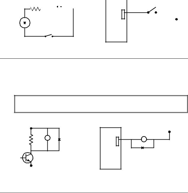
Opto-isolated Inputs
The SMC-2000 provides opto-isolated digital inputs for limit, home, abort, and the uncommitted inputs. All inputs have the same common ground and are sinking inputs.
If nothing is connected to the inputs, no current flows, resulting in a logic one. A logic zero is generated when at least 1 mA of current flows through the input.
The 8-Axis SMC provides 16 isolated inputs and 8 additional TTL inputs.
SMC-2000 User's Guide |
Hardware Interface • 3 |
+24 |
|
|
|
SMC |
|
|
||
|
0 V |
|
|
|
SWITCH |
|||
VDC |
|
I/O |
||||||
|
|
|
|
|
||||
|
|
|
|
|
|
|
|
|
|
|
|
|
|
|
|
|
|
|
|
|
|
|
|
|
|
|
|
|
|
|
|
|
|
|
|
|
|
|
|
|
|
|
|
|
0 V
SWITCH
Figure 3-3 - Digital input diagram
Outputs
The SMC-2000 provides several output signals including eight general outputs, and four amplifier enable signals AEN. All the output signals are 24 volts and are sinking outputs. The maximum current draw is 600 mA per point, and a total of 800 mA per group of eight i.e. outputs 1-8, 9-16 ... The 8-Axis SMC provides an additional eight outputs.
WARNING: All inductive loads (Brakes, Relay Coils,...) should have a flyback diode connected across them to absorb any back EMF produced by that load. The flyback diode should be placed as close to the load as possible.
+24 |
LOAD |
|
|
+24 |
VDC |
SMC |
|
||
|
|
I/O |
LOAD |
VDC |
|
|
|
||
|
|
|
|
0 V
Figure 3-4 - Digital output diagram
Analog Inputs
The SMC-2000 has seven analog inputs configured for the range between -10V and 10V. The inputs are decoded by a 14-bit A/D decoder. The impedance of these inputs is 10 KΩ.
4 • Hardware Interface |
SMC-2000 User's Guide |
Amplifier Interface
The SMC-2000 generates +/-10 Volt range analog signal, ACMD, and ground for each axis. This signal is input to power amplifiers which have been sized to drive the motors and load. For best performance, the amplifiers should be configured for a current mode of operation with no additional compensation. The gain should be set such that a 10 Volt input results in the maximum required current.
The SMC-2000 also provides an AEN, amplifier enable signal, to control the status of the amplifier. This signal toggles when the watchdog timer activates, when a motor-off command is given, or when OE1 (Off-on-error is enabled) command is given and the position error exceeds the error limit. As shown in Figure 3-3, AEN can be used to disable the amplifier for these conditions.
The standard configuration of the AEN signal is 24 VDC active low.
|
ACMD |
INPUT |
|
|
|
|
|||
SMC-2000 |
AEN |
ENABLE |
AMP |
|
GND |
GND |
|||
|
|
|||
|
|
|
|
Figure 3-5 - Connecting AEN to an amplifier
Motors with Brakes
A separate 24 VDC power supply should be used to power the brakes because holding brakes typically generate large power spikes when they are de-energized.
Severe damage may result when connecting the same power supply to the SMC and the brake!
Yaskawa recommends that all inductive loads have a diode across them to absorb back EMF.
Step Motors
To connect step motors to the SMC 2000 you must follow this procedure:
1.For each axis that is a stepper, a jumper wire is necessary between ground pin 23 on the AE1 or AE2 connector and the axis stepper mode jumper pin on the AE connector. Newer controllers already have this jumper wire installed during assembly.
2.Connect step and direction signals from the axis connector pins with the labels, STEP (pin 12) and SEN/DIR (pin 13) to respective signals on your step motor amplifier. The signals are 5V TTL level. Consult the documentation for your step motor amplifier.
3.Configure the SMC 2000 for motor type using the MT command. You can configure the SMC 2000 for active high or active low pulses. Use the command MT 2 for active high step motor pulses and MT -2 for active low step motor pulses. See the Commands section of this manual for details.
SMC-2000 User's Guide |
Hardware Interface • 5 |
The pulse output signal has a 50% duty cycle. Step motors operate open loop and do not require encoder feedback. When a stepper is used, the auxiliary encoder for the corresponding axis is unavailable for an external connection. If an encoder is used for position feedback, connect the encoder to the main encoder input corresponding to that axis. The commanded position of the stepper can be interrogated with RP or DE. The encoder position can be interrogated with TP.
The frequency of the step motor pulses can be smoothed with the filter parameter, KS. The KS parameter has a range between 1 and 16, where 16 implies the largest amount of smoothing.
The SMC 2000 profiler commands the step motor amplifier. All SMC 2000 motion commands apply such as PR, PA, VP, CR and JG. The acceleration, acceleration, slew speed, and S-curve filtering are also used. However, since step motors run open loop, the PID filter does not function and the position error is not generated.
When configured for stepper motor operation, the SMC 2000 can accept encoder signals into the main encoder inputs. This is useful for monitoring encoder position to insure that encoder position is consistent with commanded position.
Note: When configured for step motors, the encoder inputs can not be used for closed loop position control and the auxiliary encoder inputs are not available.
6 • Hardware Interface |
SMC-2000 User's Guide |


Communication - RS232
RS232 Ports
The SMC-2000 has two RS232 ports. The main port can be configured by the factory, and the auxiliary port can be configured with the software command CC. The auxiliary port can either be configured as a general port or for the daisy-chain communications. The auxiliary port configuration can be saved using the Burn (BN) instruction. The RS232 ports also have a clock synchronizing line that allows synchronization of motion on more than one controller.
The RS232 pin-out description for the main and auxiliary port is given below. Note, the auxiliary port is essentially the same as the main port except inputs and outputs are reversed. The SMC-2000 may also be configured by the factory for RS422. These pin-outs are also listed below.
RS232 - Main Port {COM 1}
1 |
CTS (-) output |
6 |
CTS (-) output |
|
|
|
|
2 |
Transmit Data (-) output |
7 |
RTS (-) input |
|
|
|
|
3 |
Receive Data (-) input |
8 |
CTS (-) output |
|
|
|
|
4 |
RTS (-) input |
9 |
No connect - or - (5V or sample clock with jumpers) |
|
|
|
|
5 |
Ground |
|
|
|
|
|
|
|
|
|
|
RS232 - Auxiliary Port {COM 2} |
|
|
|
|
|
|
|
1 |
CTS (-) input |
6 |
CTS (-) input |
|
|
|
|
2 |
Transmit Data (-) input |
7 |
RTS (-) output |
|
|
|
|
3 |
Receive Data (-) output |
8 |
CTS (-) input |
|
|
|
|
4 |
RTS (-) output |
9 |
5V - or - (no connect or sample clock with jumpers) |
|
|
|
|
5 |
Ground |
|
|
|
|
|
|
|
|
|
|
SMC-2000 User's Guide |
Communication - RS232 • 1 |
*RS422 - Main Port {COM 1}
1 |
CTS (-) output |
6 |
CTS (+) output |
|
|
|
|
2 |
Transmit Data (-) output |
7 |
Transmit Data (+) output |
|
|
|
|
3 |
Receive Data (-) input |
8 |
Receive Data (+) input |
|
|
|
|
4 |
RTS (-) input |
9 |
RTS (+) input |
|
|
|
|
5 |
Ground |
|
|
|
|
|
|
|
|
|
|
*RS422 - Auxiliary Port {COM 2} |
|
|
|
|
|
|
|
1 |
CTS (-) input |
6 |
CTS (+) input |
|
|
|
|
2 |
Transmit Data (-) input |
7 |
Transmit Data (+) input |
|
|
|
|
3 |
Receive Data (-) output |
8 |
Receive Data (+) output |
|
|
|
|
4 |
RTS (-) output |
9 |
RTS (+) output |
|
|
|
|
5 |
Ground |
|
|
|
|
|
|
|
|
|
|
*Configured for RS422 by factory
Configuration
Configure your PC for 8-bit data, one start-bit, one stop-bit, full duplex and no parity. The baud rate for the RS232 communication is 19.2 K baud. A lower baud rate may be configured at the factory.
The RS232 main port is configured for handshake mode. In this mode, the RTS and CTS lines are used. The CTS line will go high whenever the SMC-2000 is not ready to receive additional characters. The RTS line will inhibit the SMC-2000 from sending additional characters. Note the RTS line goes high for inhibit.
The auxiliary port of the SMC-2000 can be configured either as a general port or for the daisy chain. When configured as a general port, the port can be commanded to send ASCII messages to another SMC-2000 controller or to a display terminal or panel.
(Configure Communication) at port 2. The command is in the format of: CC m,n,r,p
where m sets the baud rate, n sets for either handshake or non-handshake mode, r sets for general port or the auxiliary port, and p turns echo on or off.
m - Baud Rate - 300,1200,4800,9600,19200,38400 n - Handshake - 0=No; 1=Yes
r - Mode - 0=General Port; 1=Daisy-chain p - Echo - 0=Off; 1=On; Valid only if r=0
Note, for the handshake of the auxiliary port, the roles for the RTS and CTS lines are reversed. Example:
2 • Communication - RS232 |
SMC-2000 User's Guide |
CC 1200,0,0,1 |
Configure communication at port 2, with 1200 baud, no |
|
handshake, general port and echo turned on. |
|
|
|
|
Daisy-Chaining
Up to eight SMC-2000 controllers may be connected in a daisy chain. The daisy-chain connection is straightforward. One SMC-2000 is connected to the host terminal via the RS232 at port 1, or the main port. Port 2, or the auxiliary port, of that SMC-2000 is then brought into port 1 of the next SMC-2000, and so on. The default address of the SMC-2000 is zero, if another address is required each of the SMC-2000’s must be configured by the factory. Please contact Yaskawa if your application requires daisy-chaining.
To communicate with any one of the SMC-2000s, give the command of %A, where A is the address of the SMC that you want to communicate with. All instructions following this command will be sent only to the SMC with that address. Only when a new %A command is given will the instruction be sent to another SMC. The only exception is "!" command. To talk to all the SMC-2000s in the daisy-chain at one time, insert the character "!" before the software command. All SMCs receive the command, but only address 0 will echo.
Note: The CC command must be specified to configure the port {P2} of each unit.
Example:
Problem: 6-axis motion system. Address 0 is a 4-axis |
Required Motion: |
SMC-2000-4. A 2-axis SMC-2000-2 is set for Address 1. |
|
|
|
Address 0 |
X Axis is 500 counts |
|
Y Axis is 1000 counts |
|
Z Axis is 2000 counts |
|
W Axis is 1500 counts |
|
|
Address 1 |
X Axis is 700 counts |
|
Y Axis is 1500 counts |
|
|
|
|
Software Command |
Interpretation |
|
|
%0 |
Talk only to controller 0 (SMC-2000-4) |
|
|
PR 500,1000,2000,1500 |
Specify X,Y,Z,W distances |
|
|
%1 |
Talk only to controller 1 (SMC-2000-2) |
|
|
PR 700,1500 |
Specify X,Y distances |
|
|
!BG |
Begin motion on both controllers |
|
|
|
|
Synchronizing Sample Clocks
It is possible to synchronize the sample clocks of all SMC-2000's in the daisy chain. This involves burning in the command, TM-1, in all SMC-2000's except for one SMC-2000, which will be the source. If it is necessary to synchronize the sample clocks please contact Yaskawa.
Operator Interface
To program an operator interface you need to select a port (either 1 or 2), If you select port 2 it must be configured by using the Configure Communication (CC) command as shown on page 26. You must also decide if the port will be a general port or an operator data entry port. NOTE: configuring a port as an operator data
SMC-2000 User's Guide |
Communication - RS232 • 3 |
entry port will disable ALL commands sent to that port, see Operator Data Entry Mode in chapter 7 for a complete description. All serial commands, such as message (MG) or input variable (IN) default to port 1. To assign serial commands to port 2, you must follow the command with a “{P2}” such as:
IN {P2} “Enter a value”,VALUE
Which will send out the prompt “Enter a value” to port 2, then wait until a return or semi-colon is sent out port 2, and assign the value of the preceding characters to the variable VALUE.
Controller Response to Data
Most SMC-2000 instructions are represented by two characters followed by the appropriate parameters. Each instruction must be terminated by a carriage return or semicolon.
Instructions are sent in ASCII, and the SMC-2000 decodes each ASCII character (one byte) one at a time. It takes approximately .5 msec for the controller to decode each command.
After the instruction is decoded, the SMC-2000 returns a colon (:) if the instruction was valid or a question mark
(?) if the instruction was not valid or was not recognized.
For instructions requiring data, such at Tell Position (TP), the SMC-2000 will return the data followed by a carriage return, line feed and : .
It is good practice to check for : after each command is sent to prevent errors. An echo function is provided to enable associating the SMC-2000 response with the data sent. The echo is enabled by sending the command EO 1 to the controller.
4 • Communication - RS232 |
SMC-2000 User's Guide |
Loading...