


 Loading...
TM
YASKAWA AC Drive
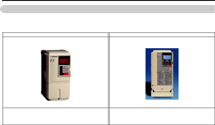
F7 to A1000
Product Transition Guide
Type: CIMR-F7U 
Models: 240 V Class, Three-Phase Input: 1/2 to 150 HP Heavy Duty* 1/2 to 175 HP Normal Duty 480 V Class, Three-Phase Input: 1/2 to 500 HP Heavy Duty* 1/2 to 600 HP Normal Duty
Type: CIMR-AU 
Models: 240 V Class, Three-Phase Input: 3/4 to 150 HP Heavy Duty* 3/4 to 175 HP Normal Duty 480 V Class, Three-Phase Input: 3/4 to 900 HP Heavy Duty*
3/4 to 1000 HP Normal Duty
* Note: This guide lists only comparable models. Refer to the product catalog for a list of all available models. The Heavy Duty drive ratings (HD) are primarily used in this guide to facilitate data comparison.
DOCUMENT NO. PL.A1000.02

2 |
YASKAWA PL.A1000.02 F7 to A1000 - Product Transition Guide |

Replacing F7 with A1000
1 FEATURE OVERVIEW . . . . . . . . . . . . . . . . . . . . . . . . . . . . . . . . . . . . . . . . . . . . . 4 2 F7 TO A1000 FEATURE SPECIFICATIONS . . . . . . . . . . . . . . . . . . . . . . . . . . . . 5 3 DIGITAL OPERATOR COMPARISON. . . . . . . . . . . . . . . . . . . . . . . . . . . . . . . . . 6 4 FRONT COVER & COOLING FAN COMPARISON. . . . . . . . . . . . . . . . . . . . . . . 7 5 NAMEPLATE/LABELING DIFFERENCES . . . . . . . . . . . . . . . . . . . . . . . . . . . . . 8 6 MAIN CONTROL PCB COMPARISON . . . . . . . . . . . . . . . . . . . . . . . . . . . . . . . . 9 7 A1000 DRIVE OPTIONS. . . . . . . . . . . . . . . . . . . . . . . . . . . . . . . . . . . . . . . . . . . 15 8 DETAILS ON NEW A1000 FEATURES AND FUNCTIONS . . . . . . . . . . . . . . . 16 9 APPENDIX 1 RATINGS . . . . . . . . . . . . . . . . . . . . . . . . . . . . . . . . . . . . . . . . . . . 20 10 APPENDIX 2 PARAMETER CROSS REFERENCE . . . . . . . . . . . . . . . . . . . . . 30 11 APPENDIX 3 TERMINAL SIZE AND WIRE GAUGE . . . . . . . . . . . . . . . . . . . . . 56
YASKAWA PL.A1000.02 F7 to A1000 - Product Transition Guide |
3 |
1 Feature Overview
1 Feature Overview
This document details differences between the F7 and A1000 product to assist in product transistion and new product introductions.
F7 Drive |
|
A1000 Drive |
The F7 drive is primarily used for general purpose industrial applications.
The A1000 drive is primarily used for general purpose and high performance industrial applications, including those that require precise torque and speed control as well as control of both induction and permanent magnet motors.
Table 1 Key A1000 Features and Functions
Key A1000 Features and Functions |
Key A1000 Features and Functions |
|
• Closed or open loop vector control for outstanding regulation, torque production, and |
• Auxiliary Control Power Unit maximizes production time and efficiency by maintaining |
|
position control capability |
network communication while main power is removed |
|
• Continuous Auto-tuning optimizes performance by compensating for changes in motor |
• Embedded Safe Torque Off minimizes downtime for applications requiring occasional |
|
temperature |
intervention (SIL CL2, PLd, Category 3) |
|
• High Frequency Injection enables high precision open loop control of Interior Permanent |
• Embedded function blocks, programmable with DriveWorksEZ, provide additional |
|
Magnet Motors |
application flexibility and the opportunity to eliminate separate controllers |
|
• Fast acting current and voltage limiters help achieve continuous drive operation during |
• USB Copy Unit and Keypad configuration storage provide speed and convenience for |
|
periods of excessive demand |
duplicate configuration of multiple drives |
|
• High Slip Braking reduces installation cost and the need for dynamic braking resistors |
• Removable terminal board with configuration storage provides convenience of |
|
configuration backup |
||
|
||
• Communication options for all major industrial networks provides high speed control and |
• Made with RoHS compliant materials |
|
monitoring, reducing installation cost |
||
|
||
• DriveWizard computer software and Application Sets for easy configuration |
• Integrated DC Reactor (standard on 30 HP and larger) for input harmonic reduction |
4 |
YASKAWA PL.A1000.02 F7 to A1000 - Product Transition Guide |

2 F7 to A1000 Feature Specifications
2 F7 to A1000 Feature Specifications
Table 2 Feature Specifications
Feature |
Item |
Yaskawa F7 |
Yaskawa A1000 |
|
|
200 V |
240V 0.5 to 150 HP (HD) 0.5 to 175 HP (ND) <1> |
240 V 0.75 to 150 HP (HD) 0.75 to 175 HP (ND) |
|
HP Range |
400 V |
480V 0.5 to 500 HP (HD) 0.5 to 600 HP (ND) |
480 V 0.75 to 900 HP (HD) 0.75 to 1000 HP (ND) |
|
|
600 V |
— |
600 V 2 to 250 HP (ND) |
|
Input Voltage |
Rated Voltage |
3-phase, 200-240 Vac |
3-phase, 200-240 Vac |
|
3-phase, 380-480 Vac |
||||
3-phase, 380-480 Vac |
||||
|
|
3-phase, 500-600 Vac |
||
|
|
|
||
Motor types |
— |
Induction |
Induction, Permanent Magnet |
|
PWM Carrier Frequency |
Range |
See Appendix 1 |
See Appendix 1 |
|
Maximum Output Frequency |
Hz |
300 Hz (HD) 400 Hz (ND) |
400 Hz (1000 Hz optional) |
|
1000 Hz optional |
||||
|
|
|
||
Keypad Design |
Display |
5 Line X 16 Character LCD |
5 Line X 16 Character LCD |
|
Copy Function |
Yes |
Yes |
||
|
||||
Digital Input Terminal |
NPN/PNP |
Switchable NPN/PNP |
Switchable NPN/PNP |
|
Digital output Terminal |
Open Collector |
0 |
0 |
|
Relay Output |
3 x Form A, 1 x Form C |
3 x Form A, 1 x Form C |
||
|
||||
|
|
2 channels |
2 channels with independent level selections |
|
Analog Output |
Output Level |
with independent level selections |
||
0-10 V (10 bit plus sign) or |
||||
0-10 V (10 bit plus sign) or |
||||
|
|
–10-+10 V or 10 bit plus sign or 4-20 ma 10 bit |
||
|
|
–10-+10 V or 10 bit plus sign or 4-20 ma 10 bit |
||
|
|
|
||
Pulse Input |
Qty: |
1 |
1 |
|
Input Frequency |
1-32 kHz |
1-32 kHz |
||
|
||||
Pulse Output |
Qty: |
1 |
1 |
|
Output Frequency |
1-32 kHz |
1-32 kHz |
||
|
||||
Quick Disconnect Terminals |
Type |
Yes |
Yes |
|
Auto Tuning |
Methods |
Rotating, Stationary |
Rotating, Stationary, Continuous, Inertia /ASR |
|
Preset Speeds |
Qty. |
17 |
17 |
|
Speed Search |
Bi/Uni-Directional |
Bi-Directional |
Bi-Directional |
|
Method |
Current/Speed |
Current/Speed Estimation |
||
|
||||
Auto Restart |
Time Between Attemps |
0.0 – 5.0 sec (selectable) |
0.0 – 5.0 sec (selectable) |
|
Energy Savings Mode |
Man/Auto |
Man/Auto |
Man/Auto |
|
DC Injection Function |
At Start/At Stop |
At Start/At Stop +HSB during stop |
At Start/At Stop +HSB during stop |
|
Braking Function |
DB Transistor |
Built-in to 25 HP |
Built-in to 40 HP (HD) |
|
Special |
High Slip Braking |
High Slip/Over-excitation Braking |
||
|
||||
Cooling Fan On/Off Control |
Power/Run |
Run Based |
Selectable Always Active/During Run |
|
Timer Function |
On/Off Delay |
On/Off Delay (0-3000 s) |
On/Off Delay (0-3000 s) |
|
Fault Code Additions |
— |
10 additional |
10 with elapsed time stamp |
|
|
|
Stall Prevention |
Stall Prevention |
|
Torque Limit/Current Limit/ |
— |
During Accel/Run/Decel (V/F) |
During Accel/Run/Decel (V/F) |
|
Stall Prevention |
Torque Limit in 4 Quadrants (Vector) |
Torque Limit in 4 Quadrants (Vector) |
||
|
||||
|
|
Software Current Limit (HD=150 %, ND=120 %) |
Software Current Limit (HD=150 %, ND=120 %) |
|
|
— |
12 Pulse: 30 HP and Above |
Filters/Reactors (Options) |
|
|
Filters/Reactors (Options) |
|||
|
|
|
||
Harmonic Counter Measures |
Built-In DC Bus Reactor |
240 Vac:30-150 HP (HD) |
240 Vac: 30-175 HP (ND) |
|
|
480 Vac: 30-1000 HP (ND) |
|||
|
480 Vac: 30-500 HP (HD) |
|||
|
|
600 Vac: 30-250 HP (ND) |
||
|
|
|
||
Ambient Temperature |
ºC |
-10ºC ~ +40ºC (IP21) |
-10 to +50°C (Open Chassis Installation) |
|
-10ºC ~ +45ºC (IP00) |
-10 to +40°C (Chassis with zero side clearance, or Type 1) |
|||
|
|
|||
Storage Temperature |
ºC |
-20ºC ~ +60ºC |
-20ºC ~ +60ºC |
|
|
Standard |
Modbus RTU via terminal I/O RS485/422 |
Modbus RTU |
|
|
via terminal I/O RS485/422 |
|||
Network Communications |
|
|
||
Optional |
DeviceNet, Profibus-DP, ControlNet, Ethernet |
DeviceNet, Profibus-DP, ProfiNet, Ethernet, |
||
|
||||
|
Modbus TCP/IP, Mechatrolink |
|||
|
|
|
||
Unique Feature/Function |
— |
HSB – High Slip Braking |
Over-excitation Braking |
<1> HD = Heavy Duty, ND = Normal Duty
YASKAWA PL.A1000.02 F7 to A1000 - Product Transition Guide |
5 |
3 Digital Operator Comparison
3 Digital Operator Comparison
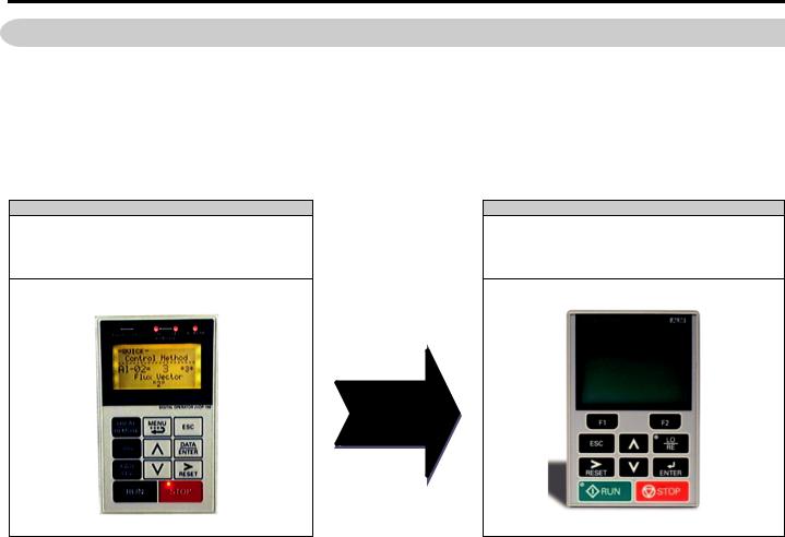
•Enhanced LCD operator with built-in copy function and parameter verify for A1000
•Soft Keys simplify operation and programming
•Optional LED operator available for A1000
•LCD contrast adjustment
•Simplified parameter grouping for easier navigation and set-up
•The A1000 has a new layout for faster parameter selection
Table 3 Digital Operator
F7 Operator
LCD Backlit Display
5 Line x 16 Characters
New A1000 Operator
LCD Backlit Display
5 Line x 16 Characters
New Button Layout
Soft Keys (F1/F2)
Smaller
•A1000 copy keypad is capable of uploading all of the parameter settings from the A1000 drive memory.
•Upload of F7 parameters to the A1000 is not available.
•A1000 drives must have the same software version, model, and control mode to copy parameters between A1000 drives.
•A Quick Start menu is added to aid in simple start up.
•The Quick Start menu consists of 26 parameters. The advanced menu offers full parameter access.
•There is a new button layout for quicker drive navigation.
|
Table 4 Menu Structure Comparison |
|
|
|
|
F7 |
|
A1000 |
Operation “DRIVE” |
|
Operation |
|
|
|
Quick Setting “QUICK” |
|
Auto-Tuning |
Programming “ADV” |
|
Programming |
|
|
|
Modified Constants “VERIFY” |
|
Quick Settings |
|
|
|
Auto-Tuning “A.TUNE” |
|
Modified Constants |
— |
|
Monitor Menu |
|
|
|
6 |
YASKAWA PL.A1000.02 F7 to A1000 - Product Transition Guide |
4 Front Cover & Cooling Fan Comparison
4 Front Cover & Cooling Fan Comparison
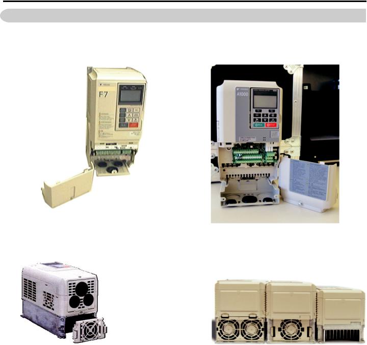
F7 - Split Front Cover |
A1000 - Split Front Cover |
|
The A1000 is provided with a split cover to allow terminal only access. The split cover limits |
|
exposure to the control PCB and power structure during wiring. |
F7 Modular Cooling |
A1000 - New Modular Top-Mounted Cooling Fan |
•The A1000 features an easy to remove top mounted heat sink fan.
•Fan operation is parameter controlled.
•Fan operation time can be monitored for preventative maintenance.
YASKAWA PL.A1000.02 F7 to A1000 - Product Transition Guide |
7 |
5 Nameplate/Labeling Differences
5 Nameplate/Labeling Differences
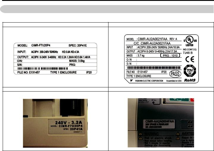
Table 5 Nameplates and Front Labels
F7 Side Nameplate |
A1000 Side Nameplate |
F7 Front Label |
A1000 Front Label |
8 |
YASKAWA PL.A1000.02 F7 to A1000 - Product Transition Guide |
6 Main Control PCB Comparison
6 Main Control PCB Comparison
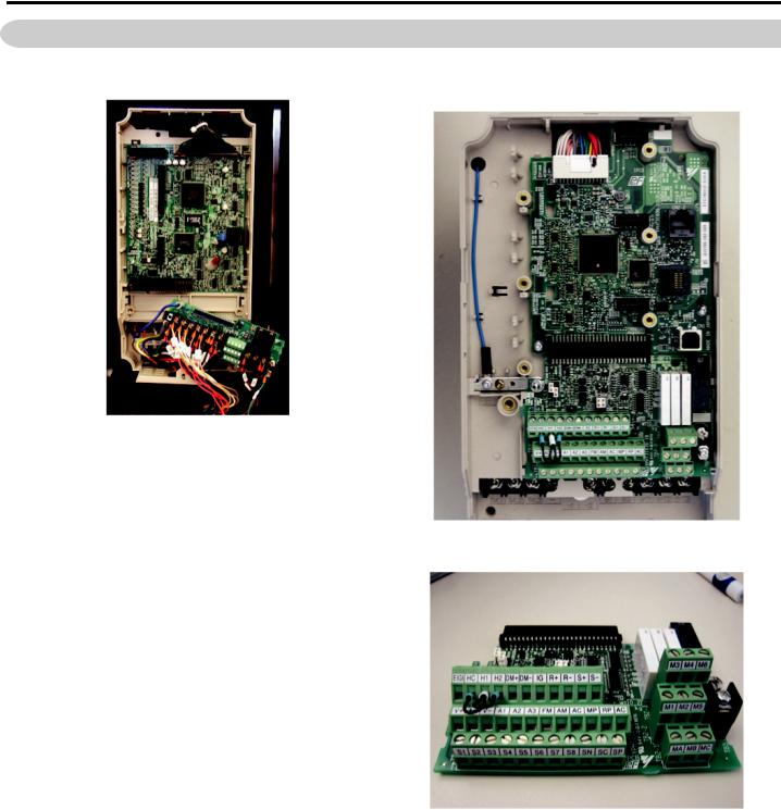
F7 Control PCB |
New A1000 Control PCB |
A1000 Removable Terminal Board
YASKAWA PL.A1000.02 F7 to A1000 - Product Transition Guide |
9 |
6Main Control PCB Comparison
Terminal Board Set-Up Comparison
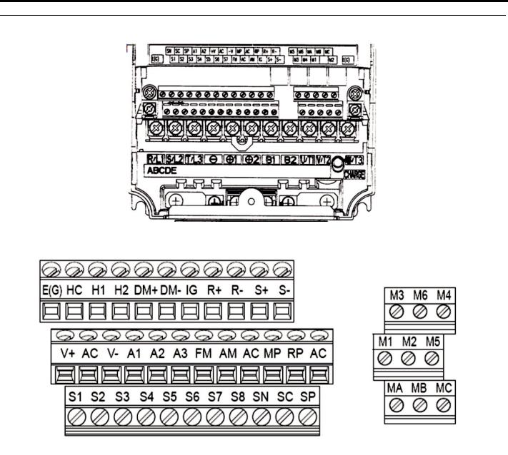
Figure 1 F7 Terminal Board Configuration
Figure 2 A1000 Terminal Board Configuration
10 |
YASKAWA PL.A1000.02 F7 to A1000 - Product Transition Guide |
6 Main Control PCB Comparison
F7 to A1000 Terminal Comparison
Table 6 Factory Default Terminal Functions 2-Wire Control
|
F7 Terminal |
|
A1000 Terminal (Designations similar to F7) |
|||
Type |
F7 Terminal |
Default Function |
A1000 Terminal |
Default Function |
A1000 Description |
|
|
S1 |
Forward run/stop command |
S1 |
Forward run/stop |
|
|
|
S2 |
Reverse run/stop command |
S2 |
Reverse run/stop |
Multi-function inputs 1-8 |
|
|
S3 |
External fault input |
S3 |
External fault, N.O. |
||
|
|
|||||
|
S4 |
Fault reset |
S4 |
Fault reset |
Photocoupler |
|
|
S5 |
Multi-step speed reference 1 |
S5 |
Multi-step speed reference 1 |
24 Vdc, 8 mA |
|
|
(Master/auxiliary switch) |
Set the S3 jumper to select |
||||
|
|
|
|
|
between sinking, sourcing |
|
|
S6 |
Multi-step speed reference 2 |
S6 |
Multi-step speed reference 2 |
||
Digital Input Signals |
mode, and the power supply. |
|||||
S7 |
Jog frequency reference |
S7 |
Jog reference |
|
||
|
|
|||||
|
S8 |
External baseblock N.O. |
S8 |
External baseblock |
|
|
|
SC |
Factory connected to SP |
SC |
Multi-function input |
— |
|
|
common |
|||||
|
|
|
|
|
||
|
SN |
Digital input common |
SN |
Digital input power supply |
24 Vdc power supply for |
|
|
0 V |
digital inputs, 150 mA max |
||||
|
|
|
|
|||
|
SP |
Factory connected to SC |
SP |
Digital input power supply |
(only when not using digital |
|
|
+24 Vdc |
input option DI-A3) |
||||
|
|
|
|
|||
|
|
|
H1 |
Safe Disable input 1 |
• 24 Vdc, 8mA |
|
|
|
|
|
|
• One or both open: Output |
|
|
|
|
H2 |
Safe Disable input 2 |
||
|
|
|
disabled |
|||
|
|
|
|
|
||
|
|
|
|
|
• Both closed: Normal |
|
|
|
|
|
|
operation |
|
|
|
|
|
|
• Internal impedance: 3.3 kΩ |
|
Safe Disable Inputs |
— |
— |
|
|
• Of time of at least 1 ms |
|
|
Safe Disable function |
Disconnect the wire jumpers |
||||
|
|
HC |
||||
|
|
|
shorting terminals H1, H2, |
|||
|
|
|
common |
|||
|
|
|
|
and HC to use the Safe |
||
|
|
|
|
|
||
|
|
|
|
|
Disable inputs. Set the S5 |
|
|
|
|
|
|
jumper to select between |
|
|
|
|
|
|
sinking, sourcing mode, and |
|
|
|
|
|
|
the power supply. |
|
|
|
|
|
|
Input frequency range: 0 to 32 |
|
|
|
|
|
|
kHz |
|
|
RP |
Pulse input |
RP |
Multi-function pulse train |
Signal Duty Cycle: 30 to 70 % |
|
|
input (frequency reference) |
High level: 3.5 to 13.2 Vdc, |
||||
|
|
|
|
|||
|
|
|
|
|
low level: 0.0 to 0.8 Vdc |
|
|
|
|
|
|
Input impedance: 3 kΩ |
|
|
+V |
+15 Vdc power output |
+V |
Power supply for analog |
10.5 Vdc (max allowable |
|
|
inputs |
current 20 mA) |
||||
|
|
|
|
|||
|
-V |
-15 Vdc power output |
-V |
Power supply for analog |
-10.5 Vdc (max allowable |
|
|
inputs |
current 20 mA) |
||||
|
|
|
|
|||
|
A1 |
Analog input or speed |
A1 |
Multi-function analog input |
-10 to 10 Vdc, 0 to 10 Vdc |
|
|
command |
1 (Frequency reference bias) |
(input impedance: 20 kΩ) |
|||
|
|
|
||||
|
|
|
|
|
-10 to 10 Vdc, 0 to 10 Vdc |
|
Analog Input Signals |
|
|
|
|
(input impedance: 20 kΩ) |
|
A2 |
Add to terminal A1 |
A2 |
Multi-function analog input |
4 to 20 mA, 0 to 20 mA (input |
||
|
impedance: 250 kΩ) |
|||||
|
2 (Frequency reference bias) |
|||||
|
|
|
|
Voltage or current input must |
||
|
|
|
|
|
be selected by DIP switch S1 |
|
|
|
|
|
|
and H3-09. |
|
|
|
|
|
|
-10 to 10 Vdc, 0 to 10 Vdc |
|
|
|
|
|
Multi-function analog input |
(input impedance: 20 kΩ) |
|
|
|
|
|
Use DIP switch S4 on the |
||
|
A3 |
Aux. frequency reference 1 |
A3 |
3 (Auxiliary frequency |
||
|
terminal board to select |
|||||
|
|
|
|
reference)/PTC input |
||
|
|
|
|
between analog and PTC |
||
|
|
|
|
|
||
|
|
|
|
|
input |
|
|
AC |
Analog common |
AC |
Analog frequency reference |
0 V |
|
|
common |
|||||
|
|
|
|
|
||
|
E(G) |
Shield wire, optional ground |
E(G) |
Ground for shielded lines |
— |
|
|
line connection point |
and option cards |
||||
|
|
|
|
|||
|
M1 |
During run |
M1 |
During run |
• Multi-function digital |
|
|
M2 |
(N.O. contact) |
M2 |
(closed at run) |
outputs, |
|
Digital Output Signals |
M3 |
Zero speed |
M3 |
Zero speed |
• N.O. contacts, 30 Vdc, |
|
10 mA to 1 A |
||||||
M4 |
(N.O. contact) |
M4 |
(closed at zero speed) |
|||
|
• 250 Vac, 10 mA to 1 A |
|||||
|
M5 |
Frequency agree |
M5 |
Speed Agree 1 |
• Minimum load: 5 Vdc, |
|
|
M6 |
(N.O. contact) |
M6 |
(closed at speed agree) |
10 mA |
|
YASKAWA PL.A1000.02 F7 to A1000 - Product Transition Guide |
11 |

6 Main Control PCB Comparison
|
F7 Terminal |
|
A1000 Terminal (Designations similar to F7) |
|||
Type |
F7 Terminal |
Default Function |
A1000 Terminal |
Default Function |
A1000 Description |
|
|
MA |
Fault output signal |
MA |
N.O. |
30 Vdc, 10 mA to 1 A; |
|
Fault Relay |
MB |
MB |
N.C. output |
|||
(SPDT) |
250 Vac, 10 mA to 1 A |
|||||
|
MC |
MC |
Fault output common |
|||
|
|
|
||||
|
FM |
Output frequency |
FM |
Analog monitor output 1 |
|
|
|
(Output frequency) |
-10 to +10 Vdc, or |
||||
|
|
|
|
|||
|
AM |
Output current |
AM |
Analog monitor output 2 |
0 to +10 Vdc |
|
Analog Output Signals |
(Output current) |
|
||||
|
|
|
|
|||
|
AC |
Analog common |
AC |
Monitor common |
0 V |
|
|
MP |
Pulse monitor |
MP |
Pulse train output (Output |
32 kHz (max) |
|
|
frequency) |
|||||
|
|
|
|
|
||
|
R+ |
Modbus communication |
R+ |
Communications input (+) |
MEMOBUS/Modbus |
|
|
|
Differential input, |
|
|
||
|
R- |
R- |
Communications input (-) |
communication: Use an RS- |
||
|
PHC isolation |
|||||
|
485 or RS-422 cable to |
|||||
|
|
|
|
|||
RS-485/422 |
S+ |
Modbus communication |
S+ |
Communications output (+) |
connect the drive. |
|
|
|
Differential output, |
|
|
RS-485/422 MEMOBUS/ |
|
|
S- |
S- |
Communications output (-) |
|||
|
PHC isolation |
Modbus comm. protocol: |
||||
|
IG |
Signal common |
IG |
Shield ground |
115.2 kbps (max.) |
|
|
|
|||||
|
— |
— |
DM+ |
Safety monitor output |
Output status of Safe Disable |
|
|
|
|
|
|
function Closed when both |
|
|
|
|
|
|
||
Safety Monitor Output |
|
|
|
Safety monitor output |
Safe Disable channels are |
|
— |
— |
DM- |
closed. |
|||
|
common |
|||||
|
|
|
|
Open Collector: +48 Vdc 50 |
||
|
|
|
|
|
mA maximum |
|
12 |
YASKAWA PL.A1000.02 F7 to A1000 - Product Transition Guide |

6 Main Control PCB Comparison
Digital Inputs 1-2
24Vdc, 8mA
|
2-Wire |
|
|
External Fault |
|
|
|
|
|
|
|
|
|
|
|
|
|
|
|
|
|
|
|
|
|
|
|
|
|
||||||||||||||||
|
|
|
Fault Reset |
|
|
|
|
|
|
|
|
|
|
|
|
|
|
|
|
|
|
|
|
|
|
|
|
|
|||||||||||||||||
|
Control |
|
|
|
|
|
|
|
|
|
|
|
|
|
|
|
|
|
|
|
|
|
|
|
|
|
|||||||||||||||||||
|
|
|
|
|
|
|
|
|
|
|
|
|
|
|
|
|
|
|
|
|
|
|
|
|
|
||||||||||||||||||||
|
|
|
Multi-Step Ref 1 |
|
|
|
|
|
|
|
|
|
|
|
|
|
|
|
|
|
|
|
|
|
|
|
|||||||||||||||||||
|
Multi-function |
|
|
|
|
|
|
|
|
|
|
|
|
|
|
|
|
|
|
|
|
|
|
|
|
||||||||||||||||||||
|
|
|
|
|
|
|
|
|
|
|
|
|
|
|
|
|
|
|
|
|
|
|
|
|
|||||||||||||||||||||
|
|
|
|
|
|
|
|
|
|
|
|
|
|
|
|
|
|
|
|
|
|
|
|
|
|
|
|
|
|
|
|
|
|
|
|
|
|
|
|
|
|
|
|||
Digital Inputs 3-8 |
|
Multi-Step Ref 2 |
|
|
|
|
|
|
|
|
|
|
|
|
|
|
|
|
|
|
|
|
|
|
|
||||||||||||||||||||
|
24Vdc, 8mA |
|
|
|
|
|
|
|
|
|
|
|
|
|
|
|
|
|
|
|
|
|
|
|
|
|
|
|
|
|
|
|
|
|
|
|
|
|
|
|
|
|
|
||
|
Jog Reference |
|
|
|
|
|
|
|
|
|
|
|
|
|
|
|
|
|
|
|
|
|
|
|
|
|
|||||||||||||||||||
|
|
|
|
|
|
|
|
|
|
|
|
|
|
|
|
|
|
|
|
|
|
|
|
|
|
|
|
||||||||||||||||||
|
|
|
|
|
|
|
|
|
|
|
|
|
|
|
|
|
|
|
|
|
|
|
|
|
|
|
|
||||||||||||||||||
|
|
|
|
|
Baseblock |
|
|
|
|
|
|
|
|
|
|
|
|
|
|
|
|
|
|
|
|
|
|
|
|||||||||||||||||
|
|
|
|
|
|
|
|
|
|
|
|
|
|
|
|
|
|
|
|
|
|
|
|
|
|
|
|
||||||||||||||||||
|
|
|
|
|
|
|
|
|
|
|
|
|
|
|
|
|
|
|
|
|
|
|
|
|
|
|
|
|
|
|
|
|
|
|
|
|
|
|
|
|
|
|
|
|
|
|
|
|
|
|
|
|
|
|
|
|
|
|
|
|
|
|
|
|
|
|
|
|
|
|
|
|
|
|
|
|
|
|
|
|
|
|
|
|
|
|
|
|
|
|
|
|
|
|
|
|
|
|
|
|
|
|
|
|
|
|
|
|
|
|
|
|
|
|
|
|
|
|
|
|
|
|
|
|
|
|
|
|
|
|
|
|
|
|
|
|
|
|
|
|
|
|
|
|
|
|
|
|
|
|
|
|
|
|
|
|
|
|
|
|
|
|
|
|
|
|
|
|
|
|
|
|
|
|
|
|
|
|
|
|
|
|
|
|
|
|
|
|
|
|
|
|
|
|
|
|
|
|
|
|
|
|
|
|
|
|
|
|
|
|
|
|
|
|
|
|
|
|
|
|
|
|
|
|
|
|
|
|
|
|
|
|
|
|
|
|
|
|
|
|
|
|
|
|
|
|
|
|
|
|
|
|
|
|
|
|
|
|
|
|
|
|
|
|
|
|
|
|
|
|
|
|
|
|
|
|
|
|
|
|
|
|
|
|
|
|
|
|
|
|
|
|
|
|
|
|
|
|
|
|
|
|
|
|
|
|
|
|
|
|
|
|
|
|
|
|
|
|
|
|
|
|
|
|
|
|
|
|
|
|
|
|
|
|
|
|
|
|
|
|
|
|
|
|
|
|
|
|
|
|
|
|
|
|
|
|
|
|
|
|
|
|
|
|
|
|
|
|
|
|
|
|
|
|
|
|
|
|
|
|
|
|
|
|
|
|
|
|
|
|
|
|
|
|
|
|
|
|
|
|
|
|
|
|
|
|
|
|
|
|
|
|
|
|
|
|
|
|
|
|
|
|
|
|
|
|
|
|
|
|
|
|
|
|
|
|
|
|
|
|
|
|
|
|
|
|
|
|
|
|
|
|
|
|
|
|
|
|
|
|
|
|
|
|
|
|
|
|
|
|
|
|
|
|
|
|
|
|
|
|
|
|
|
|
|
|
|
|
|
|
|
|
|
|
|
|
|
|
|
|
|
|
|
|
|
|
|
|
|
|
|
|
|
|
|
|
|
|
|
|
|
|
|
|
|
|
|
|
|
|
|
|
|
|
|
|
|
|
|
|
|
|
|
|
|
|
|
|
|
|
|
|
|
|
|
|
|
|
|
|
|
|
|
|
|
|
|
|
|
|
|
|
|
|
|
|
|
|
|
|
|
|
|
|
|
|
|
|
|
|
|
|
|
|
|
|
|
|
|
|
|
|
|
|
|
|
|
|
|
|
|
|
|
|
|
|
|
|
|
|
|
|
|
|
|
|
|
|
|
|
|
|
|
|
|
|
|
|
|
|
|
|
|
|
|
|
|
|
|
|
|
|
|
|
|
|
|
|
|
|
|
|
|
|
|
|
|
|
|
|
|
|
|
|
|
|
|
|
|
|
|
|
|
|
|
|
|
|
|
|
|
|
|
|
|
|
|
|
|
|
|
|
|
|
|
|
|
|
|
|
|
|
|
|
|
|
|
|
|
|
|
|
|
|
|
|
|
|
|
|
|
|
|
|
|
|
|
|
|
|
|
|
|
|
|
|
|
|
|
|
|
|
|
|
|
|
|
|
|
|
|
|
|
|
|
|
|
|
|
|
|
|
|
|
|
|
|
|
|
|
|
|
|
|
|
|
|
|
|
|
|
|
|
|
|
|
|
|
|
|
|
|
|
|
|
|
|
|
|
|
|
|
|
|
|
|
|
|
|
|
|
|
|
|
|
|
|
|
|
|
|
|
|
|
|
|
|
|
|
|
|
|
|
|
|
|
|
|
|
|
|
|
|
|
|
|
|
|
|
|
|
|
|
|
|
|
|
|
|
|
|
|
|
|
|
|
|
|
|
|
|
|
|
|
|
|
|
|
|
|
|
|
|
|
|
|
|
|
|
|
|
|
|
|
|
|
|
|
|
|
|
|
|
|
|
|
|
|
|
|
|
|
|
|
|
|
|
|
|
|
|
|
|
|
|
|
|
|
|
|
|
|
|
|
|
|
|
|
|
|
|
|
|
|
|
|
|
|
|
|
|
|
|
|
|
|
|
|
|
|
|
|
|
|
|
|
|
|
|
|
|
|
|
|
|
|
|
|
|
|
|
|
|
|
|
|
|
|
|
|
|
|
|
|
|
|
|
|
|
|
|
|
|
|
|
|
|
|
|
|
|
|
|
|
|
|
|
|
|
|
|
|
|
|
|
|
|
|
|
|
|
|
|
|
|
|
|
|
|
|
|
|
|
|
|
|
|
|
|
|
|
|
|
|
|
|
|
|
|
|
|
|
|
|
|
|
|
|
|
|
|
|
|
|
|
|
|
|
|
|
|
|
|
|
|
|
|
|
|
|
|
|
|
|
|
|
|
|
|
|
|
|
|
|
|
|
|
|
|
|
|
|
|
|
|
|
|
|
|
|
|
|
|
|
|
|
|
|
|
|
|
|
|
|
|
|
|
|
|
|
|
|
|
|
|
|
|
|
|
|
|
|
|
|
|
|
|
|
|
|
|
|
|
|
|
|
|
|
|
|
|
|
|
|
|
|
|
|
|
|
|
|
|
|
|
|
|
|
|
|
|
|
|
|
|
|
|
|
|
|
|
|
|
|
|
|
|
|
|
|
|
|
|
|
|
|
|
|
|
|
|
|
|
|
|
|
|
|
|
|
|
|
|
|
|
|
|
|
|
|
|
|
|
|
|
|
|
|
|
|
|
|
|
|
|
|
|
|
|
|
|
|
|
|
|
|
|
|
|
|
|
|
|
|
|
|
|
|
|
|
|
|
|
|
|
|
|
|
|
|
|
|
|
|
|
|
|
|
|
|
|
|
|
|
|
|
|
|
|
|
|
|
|
|
|
|
|
|
|
|
|
|
|
|
|
|
|
|
|
|
|
|
|
|
|
|
|
|
|
|
|
|
|
|
|
|
|
|
|
|
|
|
|
|
|
|
|
|
|
|
|
|
|
|
|
|
|
|
|
|
|
|
|
|
|
|
|
|
|
|
|
|
|
|
|
|
|
|
|
|
|
|
|
|
|
|
|
|
|
|
|
|
|
|
|
|
|
|
|
|
|
|
|
|
|
|
|
|
|
|
|
|
|
|
|
|
|
|
|
|
|
|
|
|
|
|
|
|
|
|
|
|
|
|
|
|
|
|
|
|
|
|
|
|
|
|
|
|
|
|
|
|
|
|
|
|
|
|
|
|
|
|
|
|
|
|
|
|
|
|
|
|
|
|
|
|
|
|
|
|
|
|
|
|
|
|
|
|
|
|
|
|
|
|
|
|
|
|
|
|
|
|
|
|
|
|
|
|
|
|
|
|
|
|
|
|
|
|
|
|
|
|
|
|
|
|
|
|
|
|
|
|
|
|
|
|
|
|
|
|
|
|
|
|
|
|
|
|
|
|
|
|
|
|
|
|
|
|
|
|
|
|
|
|
|
|
|
|
|
|
|
|
|
|
|
|
|
|
|
|
|
|
|
|
|
|
|
|
|
|
|
|
|
|
|
|
|
|
|
|
|
|
|
|
|
|
|
|
|
|
|
|
|
|
|
|
|
|
|
|
|
|
|
|
|
|
|
|
|
|
|
|
|
|
|
|
|
|
|
|
|
|
|
|
|
|
|
|
|
|
|
|
|
|
|
|
|
|
|
|
|
|
|
|
|
|
|
|
|
|
|
|
|
|
|
|
|
|
|
|
|
SN |
3-Wire Control
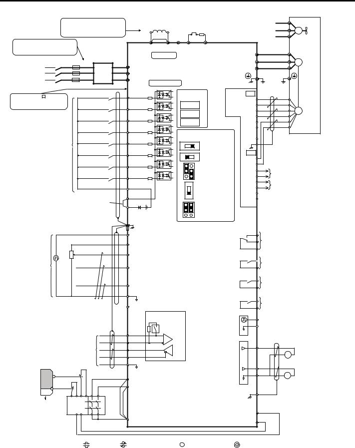
Figure 3 F7 Connection Diagram
YASKAWA PL.A1000.02 F7 to A1000 - Product Transition Guide |
13 |
6 Main Control PCB Comparison
|
|
Terminals -, +1, +2, B1, B2 are |
|
DC link choke<1>Thermal relay |
|
|
|
<15> |
|
|
||||||
|
|
|
|
|
|
FU |
|
|
||||||||
|
|
for connection options. Never |
|
(option) |
|
(option) <2> |
|
|
|
FV |
|
|
||||
|
|
connect power supply lines to |
|
U |
X |
|
|
|
|
|
M |
|||||
|
|
these terminals |
|
|
Jumper |
|
|
Braking resistor |
|
|
FW |
|
Cooling fan |
|||
|
|
|
|
|
|
|
|
|
|
|
||||||
Wiring sequence should shut off |
|
|
|
|
|
|
(option)<3> |
|
|
|
|
|
||||
|
|
+2 |
+1 |
|
|
|
|
|
|
|
|
|
||||
power to the drive when a fault |
|
|
|
|
B1 |
B2 |
|
|
|
U |
|
|
||||
output is triggered. |
|
|
|
Main Circuit |
|
|
|
|
U/T1 |
|
|
|||||
|
|
Main |
|
|
|
|
|
|
|
V |
|
|
||||
Three-Phase |
|
Fuse |
|
|
|
|
|
|
|
|
V/T2 |
|
M |
|||
S |
Switch |
|
S/L2 |
|
Drive |
|
|
W |
|
|||||||
200 to 600 V |
|
EMC |
|
|
|
W/T3 |
|
|
||||||||
Power Supply |
R |
|
|
R/L1 |
|
|
|
|
|
|
|
|
||||
50/60 Hz |
|
|
Filter |
T/L3 |
|
|
|
|
|
|
|
|
|
|
|
|
(Depending on T |
|
|
|
Control Circuit |
<4> |
|
|
|
|
|
|
|
||||
model capacity) |
|
|
|
|
|
|
|
|
|
Ground |
|
|
||||
|
|
|
|
|
|
|
|
|
|
|
|
|
|
|
||
Models CIMR-A |
4A930 and |
Forward Run / Stop |
S1 |
|
Option board |
PG X3 TB1 |
|
|
|
|||||||
4A1200 are compatible with |
|
|
|
|
connectors |
(option) |
A+ |
|
|
|
||||||
12-Phase Rectification. |
Reverse Run / Stop |
S2 |
|
|
CN5-C |
|
<6> |
A |
|
|
PG |
|||||
|
|
|
|
|
|
|
|
CN5-B |
|
|
|
B+ |
|
|
||
|
|
|
External fault |
S3 |
|
|
|
|
|
B |
|
|
|
|||
|
|
|
|
|
|
|
|
|
|
|
|
|
||||
|
|
|
|
|
CN5-A |
|
|
|
Z+ |
|
|
|
||||
|
|
|
|
|
|
|
|
|
|
|
|
|
|
|||
|
|
|
Fault reset |
|
S4 |
|
|
Terminal board |
|
|
Z |
|
|
|
||
|
|
|
|
|
|
|
|
|
|
|
|
|||||
|
|
|
|
|
|
|
|
|
|
SD |
|
|
|
|||
|
|
Multi-function |
Multi-speed step 1 |
S5 |
|
|
jumpers and switches |
|
|
|
|
|
||||
|
|
|
|
|
|
DIP Switch S1 |
|
|
FE |
|
|
|
||||
|
|
digtial inputs |
|
|
|
|
|
V |
I |
|
|
|
|
|
|
|
|
|
(default setting) |
Multi-speed step 2 |
S6 |
|
|
|
|
A2 Volt/Curr. Sel |
|
|
TB2 |
|
|
|
|
|
|
|
|
|
Off |
On |
DIP Switch S2 |
|
|
|
|
|
||||
|
|
|
|
|
|
|
|
Term. Res. On/Off |
|
IP |
|
|
|
|||
|
|
|
Jog speed |
|
S7 |
|
|
|
|
Jumper S3 |
|
|
IG |
|
|
|
|
|
|
|
|
|
|
|
|
|
|
|
a+ |
|
|
|
|
|
|
|
External Baseblock |
S8 |
|
|
|
|
H1, H2 |
|
|
A track monitor |
||||
|
|
|
|
|
|
|
Sink/Source Sel. |
|
|
a- |
||||||
|
|
|
|
|
|
|
|
|
|
|
|
|||||
|
|
|
|
|
SN |
|
|
|
PTC |
DIP Switch S4 |
|
|
b+ |
B track monitor |
||
|
|
|
|
|
|
|
|
|
|
b- |
||||||
|
|
|
|
|
|
|
|
|
A3 Analog/PTC |
|
|
|
|
|
||
|
|
|
Sink / Source mode |
SC |
|
|
|
AI |
Input Sel |
|
|
z+ |
|
|
|
|
|
|
|
|
|
|
|
|
|
z- |
|
|
|
||||
|
|
|
selection wire link |
SP |
|
|
|
|
|
|
|
|
|
|
||
|
|
|
(default: Sink) |
<5> |
|
|
|
V |
Jumper S5 |
|
|
|
|
|
|
|
|
|
|
|
+24 V <6> |
|
|
AM/FM Volt./Curr. |
|
|
|
|
|
||||
|
|
|
|
|
|
|
I |
Selection |
|
|
|
|
|
|
||
|
|
|
|
|
|
|
|
FM AM |
|
|
|
|
|
|
|
|
|
|
|
|
|
|
Shield ground terminal |
|
|
|
|
|
MA |
|
|
|
|
|
|
|
|
|
RP |
Pulse Train Input (max 32 kHz) |
|
|
|
Fault relay output |
|
|||||
|
|
|
|
<7> +V |
|
|
|
|
|
|
|
MB |
250 Vac, max. 1 A |
|||
|
|
|
|
Power supply +10.5 Vdc, max. 20 mA |
|
|
MC |
30 Vdc, max 1 A |
|
|||||||
|
|
|
2 kΩ |
|
|
|
|
|
|
|
|
|
(min. 5 Vdc, 10 mA) |
|||
|
|
|
|
A1 Analog Input 1 (Frequency Reference Bias) |
|
|
|
|
|
|
||||||
|
|
|
|
|
|
|
M1 |
Multi-function relay output (During Run) |
||||||||
Multi-function |
|
|
|
-10 to +10 Vdc (20 kΩ) |
|
|
|
|
|
|||||||
|
|
|
|
|
|
|
|
|
|
M2 |
250 Vac, max. 1 A |
|||||
analog/pulse |
|
|
A2 Analog Input 2 (Frequency Reference Bias) |
|
|
30 Vdc, max 1 A |
|
|||||||||
train inputs |
|
|
|
|
|
|
||||||||||
|
|
|
-10 to +10 Vdc |
(20 kΩ) |
|
|
|
|
|
(min. 5 Vdc, 10 mA) |
||||||
|
|
|
|
|
|
0 or 4 to 20 mA (250 Ω) <8> |
|
|
|
M3 |
Multi-function relay output (Zero Speed) |
|||||
|
|
|
|
|
A3 |
Analog Input 3 / PTC Input |
(Aux. frequency |
|
|
M4 |
250 Vac, max. 1 A |
|||||
|
|
|
|
|
|
|
30 Vdc, max 1 A |
|
||||||||
|
|
|
|
|
reference) |
|
|
|
|
|
|
|
||||
|
|
|
|
|
AC |
-10 to +10 Vdc (20 kΩ) |
<9> |
|
|
|
|
(min. 5 Vdc, 10 mA) |
||||
|
|
|
|
|
|
|
|
M5 |
Multi-function relay output (Speed Agree 1) |
|||||||
|
|
|
|
|
|
0 V |
|
|
|
|
|
|
||||
|
|
|
|
|
−V Power supply, -10.5 Vdc, max. 20 mA |
|
|
M6 |
250 Vac, max. 1 A |
|||||||
|
|
|
|
<7> |
|
|
30 Vdc, max 1 A |
|
||||||||
|
|
|
|
|
|
Termination resistor |
|
|
|
|
|
(min. 5 Vdc, 10 mA) |
||||
|
|
|
|
|
|
|
|
|
|
MP |
Multi-function pulse train output |
|||||
|
|
|
|
|
|
(120 Ω, 1/2 W) |
|
|
|
|
|
|||||
|
|
|
|
|
|
|
|
|
|
|
AC |
(Output frequency) |
||||
|
|
|
|
|
|
|
|
|
|
|
|
|
||||
|
|
|
|
|
|
DIP |
|
|
|
|
|
0 to 32 kHz (2.2 kΩ) |
||||
|
|
|
|
|
|
|
|
|
|
|
|
|||||
|
|
|
|
|
R+ |
Switch S2 |
|
|
|
|
0 V |
|
|
|
||
|
|
|
|
|
|
|
|
|
|
|
|
|
|
|||
|
|
MEMOBUS/Modbus |
|
R |
|
<10> |
|
|
|
|
FM |
|
|
Multi-function analog output 1 |
||
|
|
|
S+ |
|
|
|
|
|
|
|
|
|
||||
|
|
comm. RS485/422 |
|
S |
|
|
|
|
|
|
|
|
FM |
+ (Output frequency) |
||
|
|
max. 115.2 kBps |
|
|
|
|
|
|
|
|
|
|
-10 to +10 Vdc (2mA) |
|||
|
Safety |
|
|
IG |
|
|
|
|
<14> |
|
|
|
|
or 4 to 20 mA <13> |
||
|
switch |
|
|
|
|
|
|
|
|
AM |
|
|
Multi-function analog output 2 |
|||
|
|
S2 |
|
|
|
|
|
|
|
|
|
|
AC |
|
+ |
|
|
|
Safe Disable inputs |
H1 <11> |
|
|
|
|
|
|
AM |
(Output current) |
|||||
|
|
|
|
|
|
|
|
0 V |
|
-10 to +10 Vdc (2mA) |
||||||
|
|
|
|
|
|
|
|
|
|
|||||||
|
|
S1 |
|
|
H2 |
|
|
|
|
|
|
|
|
or 4 to 20 mA <13> |
||
|
|
|
|
|
|
|
|
|
|
|
|
|
|
|||
|
|
|
|
|
|
|
|
|
|
|
|
E (G) |
|
|
|
|
|
Open |
|
Wire |
|
|
|
|
|
|
|
|
|
EDM (Safety Electronic Device Monitor) |
|||
|
|
Safety relay / |
|
jumper |
|
|
|
|
|
|
|
|
DM+ |
|||
|
|
|
<12> |
|
|
|
|
|
|
|
|
|
|
|
||
|
|
controller |
|
HC |
|
|
|
|
|
|
|
DM |
|
|
|
|
|
|
|
|
|
|
|
|
|
|
|
|
|
|
|
||
|
|
|
|
|
|
|
|
|
|
|
|
|
|
|
|
|
|
|
|
shielded line |
twisted-pair shielded line |
|
control circuit terminal |
|
main circuit terminal |
|
|
||||||
Figure 4 A1000 Connection Diagram
14 |
YASKAWA PL.A1000.02 F7 to A1000 - Product Transition Guide |

|
|
|
7 A1000 Drive Options |
|
7 |
A1000 Drive Options |
|
||
|
|
|
|
|
|
Category |
Option Name |
Model Number |
|
Network Communication |
Profibus-DP |
SI-P3 |
||
|
|
DeviceNet |
SI-N3 |
|
|
|
Mechatrolink |
SI-T3 |
|
|
|
EtherNet/IP |
SI-EN3 |
|
|
|
Modbus TCP/IP |
SI-EM3 |
|
|
|
ProfiNET |
SI-EP3 |
|
|
|
Line Driver PG |
PG-X3 |
|
Motor Feedback |
Open Collector PG |
PG-B3 |
||
Serial Absolute FB |
FG-F3 |
|||
|
|
|||
|
|
Resolver Feedback |
PG-RT3 |
|
|
|
Analog Input |
AI-A3 |
|
|
|
Analog Output |
AO-A3 |
|
Input/Output |
|
Digital Input |
DI-A3 |
|
|
|
Digital Output |
DO-A3 |
|
|
|
120 Vac Interface Board |
(Contact factory) |
|
|
|
LCD Keypad |
JVOP-180 |
|
|
|
LED Keypad |
JVOP-182 |
|
Keypad |
|
Remote Mount Keypad Kit - Blank |
UUX000526 |
|
|
Remote Mount Keypad Kit - YEA |
UUX000527 |
||
|
|
|||
|
|
LCD Operator Extension Cable, 1 m |
UWR0051 |
|
|
|
LCD Operator Extension Cable, 3 m |
UWR0052 |
|
Control Power Unit |
24 V Control Power Unit |
PS-A10H for 480 V and 600 V class |
||
PS-A10L for 240 V class |
||||
|
|
|
||
|
|
Y-Stick USB Copy Unit |
JVOP-181 |
|
Parameter Management |
Drive Wizard Pro PC Support Tool |
DriveWizard Industrial |
||
|
|
PC Support Tool Cable |
UWR0638 USB Cable, 10 ft, male A-type to male B-type |
|
DriveWorksEZ |
DriveWorksEZ Std |
(Contact factory) |
||
DriveWorksEZ Pro |
(Contact factory) |
|||
|
|
|||
YASKAWA PL.A1000.02 F7 to A1000 - Product Transition Guide |
15 |
8 Details on New A1000 Features and Functions
8 Details on New A1000 Features and Functions
Note: This section details significant A1000 features.
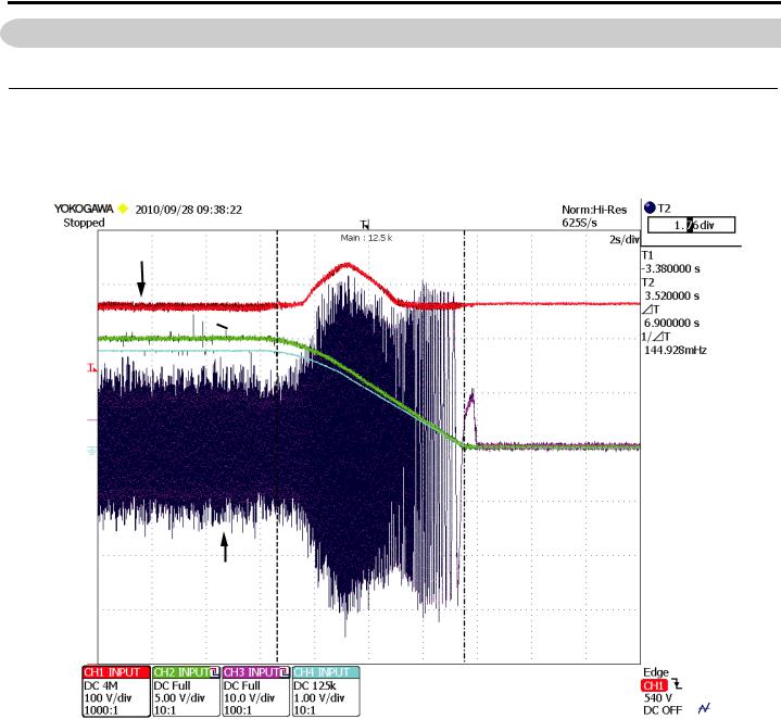
Over-Excitation Braking
This braking method allows for faster stops without the addition of a dynamic braking resistor. While still not as fast or powerful as DB, it offers a very necessary middle ground for those applications that may not require the full power of dynamic braking, saving money in hardware.
DC Bus V
Output Frequency 
Motor Speed
Output Current
Figure 5 Over-Excitation Braking
16 |
YASKAWA PL.A1000.02 F7 to A1000 - Product Transition Guide |
8 Details on New A1000 Features and Functions
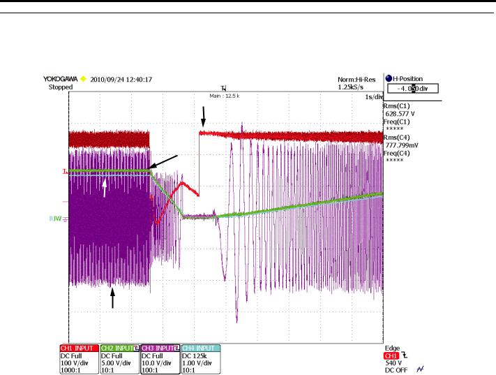
Self-Activated KEB
Internally activated Kinetic Energy Braking eliminates the need for external voltage sensing relays. Load inertia is used to decelerate the system in a controlled manner in the event of power loss. Extremely fast scan rates accommodate loads near 100 %.
DC Bus V
Output Frequency
Motor Speed
Output Current
Figure 6 Self-Activated KEB
YASKAWA PL.A1000.02 F7 to A1000 - Product Transition Guide |
17 |
8Details on New A1000 Features and Functions
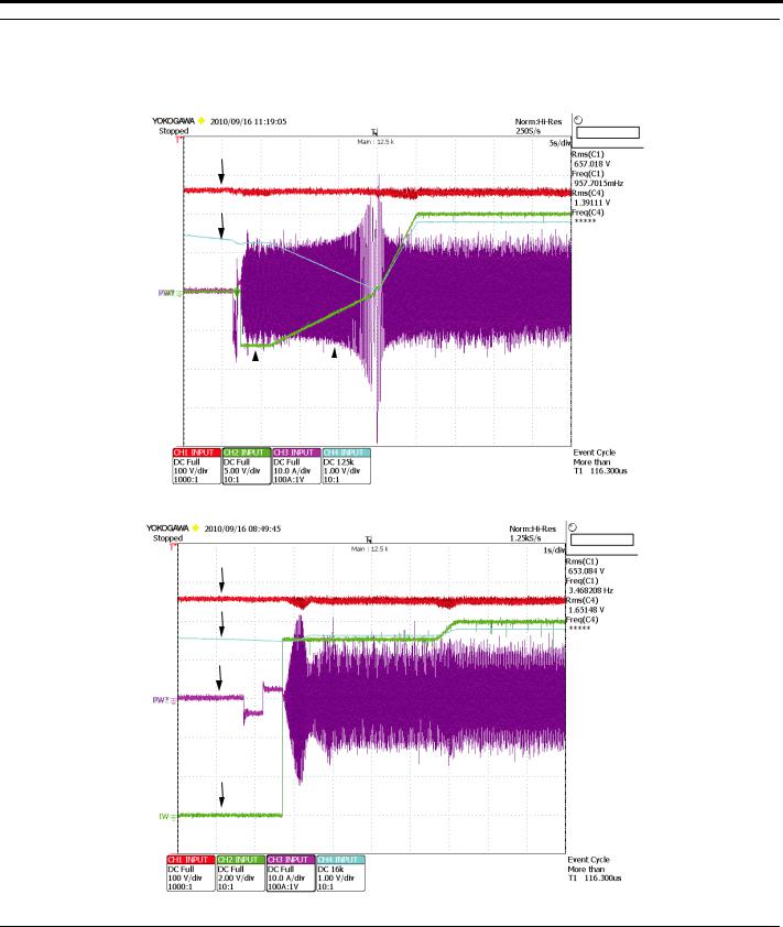
Bidirectional Speed Search
Multiple speed search methods to accommodate nearly any application. Bumpless synchronization with reverse motor rotation is easily accomplished with Speed Estimation Speed Search.
DC Bus V
Motor Speed
|
|
|
|
|
Output Frequency |
Output |
|
Current |
|
|
||||
SPEED SEARCH 45 Hz
DC Bus V
Motor Speed
Output Current
Output Frequency
SPEED SEARCH 60 Hz
Figure 7 Bi-Directional Speed Search
Top Mounted Easily Removable Cooling Fan
The heatsink fan is located on the top of the drive which improves the ease of replacement. With a tooless removal process, faulty fans are easily replaced.
18 |
YASKAWA PL.A1000.02 F7 to A1000 - Product Transition Guide |

8 Details on New A1000 Features and Functions
New “Heavy Duty” and “Normal Duty” Ratings for the A1000
The drive’s capacity is rated for two types of load characteristics, Heavy Duty (HD) and Normal Duty (ND). The table below explains the drive characteristics for HD and ND ratings. Parameter C6-01 affects the drives carrier frequency setting, and in certain models, the value of 100 % output current rating is also affected.
Table 7 Drive Selections
C6-01 Setting |
Carrier Frequency |
Output Current Ratings |
Overload Capacity |
Maximum Output Frequency |
|
|
2 kHz (default) |
|
|
|
|
0: Heavy Duty |
Can be increased w/o derate |
HD nameplate rating |
150 % |
400 Hz |
|
|
(Refer to Appendix 1) |
|
|
|
|
1: Normal Duty |
2 kHz (default) |
ND nameplate rating |
|
|
|
|
|
|
|||
Can be increased with derate |
|
120 % |
400 Hz |
||
(A1000 default) |
ND rating > HD rating |
||||
(Refer to Appendix 1) |
|
|
|||
|
(On certain models, see ratings table) |
|
|
||
|
|
|
|
|
Table 8 C6-01 Heavy/Normal Duty Setting |
|
|
Product |
C6-01 Heavy/Normal Duty Setting |
|
C6-01 Drive Duty Selection Setting |
|
0: Heavy Duty |
|
• Rated output current is the HD (Heavy Duty) rating on drive nameplate. |
|
• Overload capacity is 150 % for 1 minute. |
|
• Carrier frequency is defaulted to 2 kHz but can be increased to 8 kHz or 5 kHz w/o derating on certain models (Refer to Appendix 1) |
|
• Carrier frequency is automatically reduced when: |
|
• output frequency is < 6.0 Hz and current is >100 % |
|
• output frequency is > 6.0 Hz and current is > 112 % |
New A1000 |
• Maximum output frequency is 400 Hz (except on larger models) |
• L8-15: OL2 Characteristic selection@low speed (=1 Enabled) expedites OL2 at low output frequencies below 6 Hz. |
|
|
1: Normal Duty (default) |
|
• Output current is ND (Normal Duty) rating on drive nameplate. |
|
• Overload capacity is 120 % for 1 minute |
|
• Carrier frequency is defaulted to Swing PWM (2kHz) but can be increased with derating on most models (Refer to Appendix 1) |
|
• Carrier is automatically reduced when: |
|
• output frequency is < 6.0 Hz and current is >100 % |
|
• output frequency is > 6.0 Hz and current is > 112 % |
|
• Maximum output frequency is 400 Hz (except on certain larger models) |
|
• L8-15: OL2 Characteristic selection@low speed (=1 Enabled) expedites OL2 at low output frequencies below 6 Hz. |
|
0: Heavy Duty (default) |
|
• Rated output current is HD (Heavy Duty) rating on drive nameplate. |
|
• Overload Capacity is 150 % for 1 min. |
|
• Carrier frequency is fixed at 2 kHz |
|
• Maximum output frequency is 300 Hz. |
|
• L8-15: OL2 Characteristic selection@low speed (=1 Enabled) expedites OL2 at low output frequencies below 6 Hz. |
F7 |
2: Normal Duty 2 |
|
• Output current is ND (Normal Duty) rating on drive nameplate. |
|
• Overload capacity varies by model. (See Appendix 1) |
|
• Setting C6-02 Carrier Frequency greater than default is prohibited. (Default is highest possible setting) |
|
• Maximum output frequency is 400 Hz. |
|
• Fixed low speed protection method: Carrier is automatically lowered when output frequency is < 6.0 Hz and current is >100 %. |
|
• L8-15: OL2 Characteristic selection@low speed (=1 Enabled) expedites OL2 at low output frequencies below 6 Hz. |
YASKAWA PL.A1000.02 F7 to A1000 - Product Transition Guide |
19 |

9 Appendix 1 Ratings
9Appendix 1 Ratings
Output Amps, Carrier and Overload
Table 9 240 V Heavy Duty Ratings
240 V Heavy Duty
|
|
|
A1000 (C6-01 = 0) |
|
|
F7 Model (C6-01 = 0) |
|
|||
NEC HP 230 V |
NEC Amps |
A1000 |
Output Amps |
Fc |
Overload % |
F7 |
Output Amps |
Fc |
OL % |
|
kHz |
||||||||||
|
|
Model |
Heavy Duty |
Heavy |
Heavy Duty |
Model |
Heavy Duty |
kHz |
Heavy Duty |
|
|
|
CIMR-AU2A |
CIMR-F7U |
Heavy Duty |
||||||
|
|
|
Duty <1> |
|
|
|
||||
|
|
|
|
|
|
|
|
|
||
0.5 |
2.2 |
0004 |
3.2 |
2 (8) |
150 |
20P41 |
3.2 |
2 |
150 |
|
|
|
|||||||||
0.75 |
3.2 |
|
|
|
|
|
|
|
|
|
1 |
4.2 |
0006 |
5 |
2 (8) |
150 |
20P71 |
4.2 |
2 |
150 |
|
|
|
|
|
|
|
|
|
|
|
|
1.5 |
6 |
0008 |
6.9 |
2 (8) |
150 |
21P51 |
7.0 |
2 |
150 |
|
|
|
0010 |
8 |
|||||||
2 |
6.8 |
|||||||||
|
|
|
|
|
|
|||||
|
|
|
|
|
|
|
|
|||
3 |
9.6 |
0012 |
11 |
2 (8) |
150 |
22P21 |
9.6 |
2 |
150 |
|
|
|
|
|
|||||||
0018 |
14 |
2 (8) |
150 |
|||||||
|
|
|
|
|
|
|||||
|
|
|
|
|
|
|
|
|
|
|
5 |
15.2 |
0021 |
17.5 |
2 (8) |
150 |
23P71 |
15.2 |
2 |
150 |
|
|
|
|
|
|
|
|
|
|
|
|
7.5 |
22 |
0030 |
25 |
2 (8) |
150 |
25P51 |
23 |
2 |
150 |
|
|
|
|
|
|
|
|
|
|
|
|
10 |
28 |
0040 |
33 |
2 (8) |
150 |
27P51 |
31 |
2 |
150 |
|
|
|
|
|
|
|
|
|
|
|
|
15 |
42 |
0056 |
47 |
2 (8) |
150 |
20111 |
45 |
2 |
150 |
|
|
|
|
|
|
|
|
|
|
|
|
20 |
54 |
0069 |
60 |
2 (8) |
150 |
20151 |
58 |
2 |
150 |
|
|
|
|
|
|
|
|
|
|
|
|
25 |
68 |
0081 |
75 |
2 (8) |
150 |
20181 |
71 |
2 |
150 |
|
|
|
|
|
|
|
|
|
|
|
|
30 |
80 |
0110 |
85 |
2 (8) |
150 |
20221 |
85 |
2 |
150 |
|
|
|
|
|
|
|
|
|
|
|
|
40 |
104 |
0138 |
115 |
2 (8) |
150 |
20301 |
115 |
2 |
150 |
|
|
|
|
|
|
|
|
|
|
|
|
50 |
130 |
0169 |
145 |
2 (5) |
150 |
20371 |
145 |
2 |
150 |
|
|
|
|
|
|
|
|
|
|
|
|
60 |
154 |
0211 |
180 |
2 (5) |
150 |
20451 |
180 |
2 |
150 |
|
|
|
|
|
|
|
|
|
|
|
|
75 |
192 |
0250 |
215 |
2 (5) |
150 |
20551 |
215 |
2 |
150 |
|
|
|
|
|
|
|
|
|
|
|
|
100 |
248 |
0312 |
283 |
2 (5) |
150 |
20751 |
283 |
2 |
150 |
|
|
|
|
|
|
|
|
|
|
|
|
125 |
312 |
0360 |
346 |
2 (5) |
150 |
20900 |
346 |
2 |
150 |
|
|
|
|
|
|
|
|
|
|
|
|
150 |
360 |
0415 |
415 |
2 (5) |
150 |
21100 |
360 |
2 |
138 |
|
|
|
|
|
|
|
|
|
|
|
|
<1> Carrier setting in parenthesis indicates maximum value without derating (applies to HD rating only).
Table 10 240 V Normal Duty Ratings
240 V Normal Duty
|
|
|
A1000 (C6-01 = 1) |
|
|
F7 (C6-01 = 2) |
|
|||
NEC HP 230 V |
NEC Amps |
A1000 |
Output Amps |
Fc kHz |
Overload % |
F7 |
Output Amps |
Fc kHz |
Overload % |
|
|
|
Model |
Normal Duty |
NormalDuty |
Normal Duty |
Model |
Normal Duty |
Normal Duty |
Normal Duty |
|
|
|
CIMR-AU2A |
CIMR-F7U |
|||||||
|
|
|
|
|
|
|
|
|||
|
|
|
|
|
|
|
|
|
|
|
0.5 |
2.2 |
0004 |
3.5 |
2 (SPWM) |
120 |
20P41 |
3.6 |
10 |
107 |
|
|
|
|||||||||
0.75 |
3.2 |
|||||||||
|
|
|
|
|
|
|
|
|||
|
|
|
|
|
|
|
|
|
|
|
1 |
4.2 |
0006 |
6.0 |
2 (SPWM) |
120 |
20P71 |
4.6 |
10 |
107 |
|
|
|
|||||||||
1.5 |
6 |
|||||||||
|
|
|
|
|
|
|
|
|||
|
|
|
|
|
|
|
|
|
|
|
2 |
6.8 |
0008 |
8.0 |
2 (SPWM) |
120 |
21P51 |
7.8 |
10 |
108 |
|
|
|
|
|
|
|
|
|
|
|
|
3 |
9.6 |
0010 |
9.6 |
2 (SPWM) |
120 |
22P21 |
10.8 |
8 |
107 |
|
0012 |
12 |
|||||||||
|
|
|
|
|
|
|
|
|||
5 |
15.2 |
0018 |
17.5 |
2 (SPWM) |
120 |
23P71 |
16.8 |
10 |
107 |
|
|
|
|
|
|
|
|
|
|
|
|
7.5 |
22 |
0021 |
21 |
2 (SPWM) |
120 |
25P51 |
23 |
15 |
120 |
|
|
|
|
|
|
|
|
|
|
|
|
10 |
28 |
0030 |
30 |
2 (SPWM) |
120 |
27P51 |
31 |
15 |
102 |
|
|
|
|
|
|
|
|
|
|
|
|
15 |
42 |
0040 |
40 |
2 (SPWM) |
120 |
20111 |
46.2 |
8 |
117 |
|
|
|
|
|
|
|
|
|
|
|
|
20 |
54 |
0056 |
56 |
2 (SPWM) |
120 |
20151 |
59.4 |
10 |
117 |
|
|
|
|
|
|
|
|
|
|
|
|
20 |
YASKAWA PL.A1000.02 F7 to A1000 - Product Transition Guide |
9 Appendix 1 Ratings
240 V Normal Duty
|
|
|
A1000 (C6-01 = 1) |
|
|
F7 (C6-01 = 2) |
|
|||
NEC HP 230 V |
NEC Amps |
A1000 |
Output Amps |
Fc kHz |
Overload % |
F7 |
Output Amps |
Fc kHz |
Overload % |
|
|
|
Model |
Normal Duty |
NormalDuty |
Normal Duty |
Model |
Normal Duty |
Normal Duty |
Normal Duty |
|
|
|
CIMR-AU2A |
CIMR-F7U |
|||||||
|
|
|
|
|
|
|
|
|||
|
|
|
|
|
|
|
|
|
|
|
25 |
68 |
0069 |
69 |
2 (SPWM) |
120 |
20181 |
74.8 |
10 |
114 |
|
|
|
|
|
|
|
|
|
|
|
|
30 |
80 |
0081 |
81 |
2 (SPWM) |
120 |
20221 |
88 |
10 |
116 |
|
|
|
|
|
|
|
|
|
|
|
|
40 |
104 |
0110 |
110 |
2 (SPWM) |
120 |
20301 |
115 |
10 |
120 |
|
|
|
|
|
|
|
|
|
|
|
|
50 |
130 |
0138 |
138 |
2 (SPWM) |
120 |
20370 |
162 |
5 |
107 |
|
|
|
|
|
|
|
|||||
60 |
154 |
0169 |
169 |
2 (SPWM) |
120 |
|||||
|
|
|
|
|||||||
|
|
|
|
|
|
|
|
|
|
|
75 |
192 |
0211 |
211 |
2 (SPWM) |
120 |
20450 |
192 |
5 |
113 |
|
20550 |
215 |
8 |
120 |
|||||||
|
|
|
|
|
|
|||||
|
|
|
|
|
|
|
|
|
|
|
100 |
248 |
0250 |
250 |
2 (SPWM) |
120 |
20750 |
312 |
2 |
109 |
|
|
|
|
|
|
|
|||||
125 |
312 |
0312 |
312 |
2 (SPWM) |
120 |
|||||
|
|
|
|
|||||||
|
|
|
|
|
|
|
|
|
|
|
150 |
360 |
0360 |
360 |
2 (SPWM) |
120 |
20900 |
360 |
2 |
115 |
|
|
|
|
|
|
|
|||||
175 |
360 |
0415 |
415 |
2 (SPWM) |
120 |
21100 |
415 |
2 |
120 |
|
|
|
|
|
|||||||
|
|
|
|
|
|
|
|
|
|
|
|
|
|
Table 11 480 V Heavy Duty Ratings |
|
|
|
||||
|
|
|
|
|
|
|
|
|
|
|
|
|
|
|
480 V He avy Duty |
|
|
|
|
||
|
|
|
A1000 (C6-01 = 0) |
|
|
F7 (C6-01 = 0) |
|
|||
NEC HP 460 V |
NEC Amps |
A1000 |
Output Amps |
Fc kHz |
Overload % |
F7 |
Output Amps |
Fc kHz |
Overload % |
|
|
|
Model |
Heavy Duty |
Heavy |
Heavy Duty |
Model |
Heavy Duty |
Heavy Duty |
Heavy Duty |
|
|
|
CIMR-AU4A |
Duty <1> |
CIMR-F7U |
||||||
|
|
|
|
|
|
|
||||
0.51.1
|
|
|
0002 |
1.8 |
2 (8) |
150 |
40P41 |
1.8 |
2 |
150 |
0.75 |
1.6 |
|
||||||||
|
|
|
|
|
|
|
|
|
||
|
|
|
|
|
|
|
|
|
|
|
1 |
2.1 |
|
|
|
|
|
40P71 |
2.1 |
2 |
150 |
|
|
|
|
|
|
|
|
|
|
|
1.5 |
3 |
|
0004 |
3.4 |
2 (8) |
150 |
41P51 |
3.7 |
2 |
150 |
|
|
|
|
|
|
|
||||
2 |
3.4 |
|
|
|
|
|
||||
|
|
|
|
|
|
|
|
|
||
|
|
|
|
|
|
|
|
|
|
|
3 |
4.8 |
|
0005 |
4.8 |
2 (8) |
150 |
42P21 |
5.3 |
2 |
150 |
|
0007 |
5.5 |
||||||||
|
|
|
|
|
|
|
|
|
||
5.0 |
7.6 |
|
0009 |
7.2 |
2 (8) |
150 |
43P71 |
7.6 |
2 |
150 |
|
|
|
|
|
|
|
|
|
||
|
0011 |
9.2 |
2 (8) |
150 |
44P01 |
8.7 |
2 |
150 |
||
|
|
|
||||||||
|
|
|
|
|
|
|
|
|
|
|
7.5 |
11 |
|
0018 |
14.8 |
2 (8) |
150 |
45P51 |
12.5 |
2 |
150 |
|
|
|
|
|
|
|
|
|
|
|
10 |
14 |
|
0023 |
18 |
2 (8) |
150 |
47P51 |
17 |
2 |
150 |
|
|
|
|
|
|
|
|
|
|
|
15 |
21 |
|
0031 |
24 |
2 (8) |
150 |
40111 |
24 |
2 |
150 |
|
|
|
|
|
|
|
|
|
|
|
20 |
27 |
|
0038 |
31 |
2 (8) |
150 |
40151 |
31 |
2 |
150 |
|
|
|
|
|
|
|
|
|
|
|
25 |
34 |
|
0044 |
39 |
2 (8) |
150 |
40181 |
39 |
2 |
150 |
|
|
|
|
|
|
|
|
|
|
|
30 |
40 |
|
0058 |
45 |
2 (8) |
150 |
40221 |
45 |
2 |
150 |
|
|
|
|
|
|
|
|
|
|
|
40 |
52 |
|
0072 |
60 |
2 (8) |
150 |
40301 |
60 |
2 |
150 |
|
|
|
|
|
|
|
|
|
|
|
50 |
65 |
|
0088 |
75 |
2 (8) |
150 |
40371 |
75 |
2 |
150 |
|
|
|
|
|
|
|
||||
60 |
77 |
|
0103 |
91 |
40451 |
91 |
||||
|
|
|
|
|
||||||
|
|
|
|
|
|
|
|
|
|
|
75 |
96 |
|
0139 |
112 |
2 (5) |
150 |
40551 |
112 |
2 |
150 |
|
|
|
|
|
|
|
|
|
|
|
100 |
124 |
|
0165 |
150 |
2 (5) |
150 |
40750 |
150 |
2 |
150 |
|
|
|
|
|
|
|
|
|
|
|
125 |
156 |
|
0208 |
180 |
2 (5) |
150 |
40900 |
180 |
2 |
150 |
|
|
|
||||||||
150 |
180 |
|
0250 |
216 |
41100 |
216 |
||||
|
|
|
|
|
||||||
|
|
|
|
|
|
|
|
|
||
|
|
|
|
|
|
|
|
|
|
|
200 |
240 |
|
0296 |
260 |
2 (5) |
150 |
41320 |
260 |
2 |
150 |
|
|
|
|
|
|
|
|
|
|
|
250 |
302 |
|
0362 |
304 |
2 (5) |
150 |
41600 |
304 |
2 |
150 |
|
|
|
|
|
|
|
|
|
|
|
300 |
361 |
|
0414 |
370 |
2 (5) |
150 |
41850 |
370 |
2 |
150 |
|
|
|
|
|
|
|
|
|
|
|
350 |
414 |
|
0515 |
450 |
2 (2) |
150 |
42200 |
414 |
2 |
150 <2> |
|
|
|
|
|
|
|
|
|
|
|
400 |
477 |
|
0675 |
605 |
2 (2) |
150 |
43000 |
590 |
2 |
150 <2> |
|
|
|
||||||||
500 |
590 |
|
||||||||
|
|
|
|
|
|
|
|
|
YASKAWA PL.A1000.02 F7 to A1000 - Product Transition Guide |
21 |
Loading...