


GPD503
Table of contents
 Loading...
Magne
Tek
GPD 503
Technical Manual

- i -
GPD 503 SIMPLIFIED START-UP PROCEDURE
This procedure will quickly get you up and running by Digital Operator keypad or user supplied
remote operator control. It assumes that the GPD 503 and motor are correctly wired (see pages
1-8 thru 1-15), and start-up is to be performed without any changes to factory set constants.
Detailed information on the many other features of this drive will be found in later sections of this
manual.
INSTALLATION
1. Be certain your input voltage source, motor, and drive name plates are all marked either 230V,
460V, or 575V. Other voltages can be used, but require additional programming, see Section
2.
2. Mount drive on a vertical surface with adequate space for air circulation.
3. Remove front cover, fit conduit to bottom plate, and connect power and ground wires as
shown.
CAUTION
Be certain you connect input power to terminals L1, L2, and L3 only, or serious damage
will result. Connect motor to terminals T1, T2, and T3 only.
KEYPAD OPERATION
1. Replace cover and apply input power - keypad display shows "
F00.00
"; DRIVE, FWD, and
STOP lampS are on. Press and hold JOG key, noting direction of motor rotation. If it is
incorrect, remove power, wait for “CHARGE” light to go out, then switch wires between
terminals T1, and T2. Replace cover, and apply input power.
2. Run, Stop, and Frequency (Speed) - Here, the terms frequency and speed are used
interchangeably. A value of 60.00 (Hz) in the “
F00.00
” display equals full speed (frequency)
for common motors. Press RUN key; RUN lamp lights, STOP lamp flashes (to indicate drive is
running at zero speed). Note flashing "0" in “
F00.00
” display. Press “up arrow” key one time
to increase display frequency value to 10.00. Press DATA/ENTER key to enter speed data,
noting that motor shaft begins to turn. Repeat this procedure using “up arrow”, “down arrow”
and “right arrow” (RESET) keys to introduce various speeds, noting that the drive responds to
each new value only after the DATA/ENTER key is pressed. The “
F00.00
” display indicates
the frequency command the drive is looking at, whether it is running or not.
3. Reversing - can be selected while stopped, or while running. With the drive stopped, press
FWD/REV key and note the REV lamp lights and FWD lamp goes out. If drive is running
when this key is pressed, the drive will decelerate the motor to 0 Hz, then accelerate the
motor to the same speed in the opposite direction. You can try this while running, provided
your machine can be operated in reverse direction without damage.
4. Displays - With drive stopped, each time the DISPL (display) key is pressed, a different
function appears. The first function on power up is the “
F00.00
” display, discussed above.
Press DISPL and “
0.00
” appears; this is a display of output frequency (speed) and is
recognized as the only display without alpha characters. The next is
“
0.0A
”; the “A” indicates
this display is output amps. For other display information, refer to Section 3.
5. Faults - If an unacceptable operating condition such as code Ou (over voltage), Uu (under
voltage), OC (over current), etc. occurs, the drive will trip, and the motor will coast to a stop.
The appropriate fault code will be displayed. Examine fault code; consult Sections 6 & 7 for
fault correction procedure.

INSTALLATION OF EXTERNAL RUN/STOP SWITCH AND SPEED POTENTIOMETERS
IMPORTANT: Complete the INSTALLATION and KEYPAD OPERATION instructions before
attempting external control.
1. Disconnect power, remove cover, and wait for “CHARGE” light to go out.
2. Refer to the diagram below and connect a switch to terminals 1 and 11 using two conductor
shielded wire. This circuit is 24Vdc, very low current; use a quality rotary or toggle switch
(all wire should be 14-18AWG). Connect the shield to terminal 12 on the drive end only.
3. Install a single conductor “jumper” wire between drive terminals 5 and 11.
4. Connect a manual speed potentiometer rated 2000-3000 ohms, 1 watt minimum, using
three conductor shielded wire, with shield connected at terminal 12. Connect wires to the
potentiometer as shown, viewing potentiometer from the back. Trace wire shown closest to
the top in diagram (right side of potentiometer) and connect to terminal 17. Trace center
wire of potentiometer through and connect to terminal 16. The remaining wire will be
connected to the trim pot in step 5.
5. Connect a trim potentiometer rated 2000-3000 ohms, 1 watt minimum, as close to the drive
terminals as possible. Viewing the potentiometer from the back, connect a single conductor
wire from the left terminal to terminal 15 of the drive. Connect a short jumper wire between
the center and left terminals. Connect remaining wire from manual speed pot as shown.
- ii -
11 12 13 14 15 16 17 25 26 27
1 2 3 4 5 6 7 8 21 22
1R
Trim Pot
S1
STOP
RUN
SHIELD
WIRES
1RH
MANUAL SPEED
POTENTIOMETER
(REAR VIEW)
Shield wire
termination
GPD 503
Control Board
terminals
"Jumper
wire"

IMPORTANT: Programming is required to set up the drive for operation from external
terminals.
6. Replace cover, make sure remote switch S1 is in “Stop” position, then apply power. Note that
the DRIVE lamp is on. Press DRIVE/PROGRAM key, noting the DRIVE lamp goes out,
indicating drive is in the “Program mode”. The display will show “
Sn-01
”, which is a constant
(address). Press the “up arrow” (RESET) key three times to change constant to “
Sn-04
”.
Press the DATA/ENTER key; the display will show “
0011
”, and the left 0 will be flashing.
Using the same procedure used in setting the speed in “KEYPAD OPERATION”, move to the
first 1 and change it to 0; then move to the remaining 1 and also change it to 0. The display
should now read “
0000
”. Press the DATA/ENTER key to change the contents of constant
Sn-04 to this new value. Display will momentarily show
"
End
".
7. Press DRIVE/PROGRAM key, noting DRIVE lamp turns on; you have returned to the “Drive
mode”.
8. Calibrate manual speed pot for maximum speed at maximum rotation. With switch S1 in the
“Stop” position, press DISPL key repeatedly, stopping at the “
FXX.XX
” display. The display
will be indicating the combined setting of the trim, and manual speed pots. Turn manual
speed pot (as viewed from the front) to the right (maximum) setting. Turn trim pot slowly
until “
F59.00
” is displayed, then advance just enough to display “
F60.00
”.
9. Press DISPL key to move to output frequency display, turn switch S1 to “Run”, and adjust
motor speed with manual speed pot.
- iii -

- iv -
Cn-29 50
Cn-30 160
Cn-31
(4)
Cn-32
(4)
Cn-33
(4)
Cn-34 30
(3)
Cn-35 2.0
Cn-36 0
Cn-37
(4)
Cn-38 150
Cn-39 2.0
(4)
Cn-40
(4)
Cn-41 100
Cn-42 0.3
Un-01 N/A N/A
Un-02 N/A N/A
Un-03 N/A N/A
Un-04 N/A N/A
Un-05 N/A N/A
Un-06 N/A N/A
Un-07 N/A N/A
Un-08 N/A N/A
Un-09 N/A N/A
Un-10 N/A N/A
Sn-22 02
Sn-23 00
Sn-24 00
Sn-25 0000
Sn-26 0000
Sn-27 0010
Sn-28 0100
Cn-01 230.0
(230V)
or 460.0
(460V)
or 575.0
(575V)
Cn-02
(2)
Cn-03
(2)
Cn-04
(2)
Cn-05
(2)
Cn-06
(2)
Cn-07
(2)
Cn-08
(2)
Cn-09
(1)
Cn-10 1.5
(2)
Cn-11 50
Cn-12 0.0
Cn-13 0.0
Cn-14 100
Cn-15 0
Cn-16 0.0
Cn-17 0.0
Cn-18 0.0
Cn-19 1.0
Cn-20 0
Cn-21 0.0
Cn-22 2.0
Cn-23
(4)
Cn-24
(4)
Cn-25 00
Cn-26 160
Cn-27 0.1
Cn-28 170
An-01 0.00
An-02 0.00
An-03 0.00
An-04 0.00
An-05 0.00
An-06 0.00
An-07 0.00
An-08 0.00
An-09 6.00
bn-01 10.0
bn-02 10.0
bn-03 10.0
bn-04 10.0
bn-05 100.0
bn-06 0
bn-07 1.0
bn-08 0.0
bn-09 80
bn-10 1
bn-11 1.00
bn-12 0.50
Sn-01
(1)
Sn-02 01
Sn-03 0000
Sn-04 0011
Sn-05 0000
Sn-06 0000
Sn-07 0000
Sn-08 0100
Sn-09 0000
Sn-10 0000
Sn-11 0000
Sn-12 0100
Sn-13 0100
Sn-14 0000
Sn-15 03
Sn-16 04
Sn-17 06
Sn-18 08
Sn-19 00
Sn-20 00
Sn-21 01
QUICK REFERENCE FOR GPD 503 CONSTANTS (FACTORY SET)
CONSTANT FACTORY USER CONSTANT FACTORY USER CONSTANT FACTORY USER
NUMBER SETTING SETTING NUMBER SETTING SETTING NUMBER SETTING SETTING
(1)
Setting depends on GPD 503 rating. See Table A3-1.
(2)
Initial value is related to V/f curve selected by Sn-02 setting.
(3)
Motor rated current (Cn-09) is set at 100% level. Setting range: 10
to 200% of GPD 503 rated capacity.
(4)
Initial value differs depending on GPD 503 capacity.

-v-
Horsepower Range
RATED
HORSEPOWER
MODEL
INPUT
CT (150% OL) VT (125% OL)
NO.
1 1 DS305
2 2 DS302
3 3 DS306
5 5 DS307
7.5 7.5/10 DS308
2 10 15 DS309
3 15 20 DS310
0 20 25 DS311
V 25 30 DS322
30 40 DS323
40 50 DS2040
40/50 50 GPD503-2L40
50 60 DS2050
60 60 GPD503-2L50
60 75 DS2060
60 75 GPD503-2L60
75 100 DS2075
75 100 GPD503-2L75
100 150 DS2100
100 125 GPD503-2L100
1 1 DS313
2 2 DS304
3 3 DS314
5 5 DS315
7.5 7.5/10 DS316
10 15 DS317
4 15 20 DS318
6 20 25 DS326
0 25 30 DS325
V 30 40 DS330
40 50 DS340
50 60 DS350
60 75 DS360
75 100 DS075
75/100 100 GPD503-4L75
100 150 DS100
100 150 GPD503-4L100
150 200 DS150
150 200 GPD503-4L150
200 250 DS200
200 250 GPD503-4L200
250 300 DS250
300 400 DS303
400 500 DS400
2 3 DS5003
3 3 DS5004
5 5 DS5006
7.5 7.5 DS5009
10 10 DS5012
15 15 DS5017
5 20 20 DS5022
7 25 25 DS5027
5 30 30 DS5032
V 40 40 DS5043
50 50 DS5054
60 60 DS5064
75 75 DS5081
100 100 DS5112
125 150 DS5130
150 200 DS5172
200 200 DS5202
( "L" ) (04/27/95)

-vi-
WARNING
Do not touch circuit components until main input power has been turned off and
“CHARGE” lamp is extinguished. The capacitors are still charged and can be
quite dangerous.
Do not connect or disconnect wires and connectors while power is applied to the
circuit.
CAUTION
Know your application before using either Initialization function of Sn-03. This
constant must be set to 0000 for Drive mode operation. (See paragraph 2.25 for
additional information.)
1110 = Factory 2-Wire Control Initialization (Maintained RUN Contact)
1111 = Factory 3-Wire Control Initialization (Momentary START/STOP Contact)
Entering either Initialization code resets all constants EXCEPT Sn-01 AND Sn-02 to
factory settings, and automatically returns Sn-03 setting to 0000. If the GPD 503 is
connected for 3-Wire control and this constant is set to 1110 (2-Wire Control
Initialization), the motor may run in reverse direction WITHOUT A RUN COMMAND
APPLIED. Equipment damage or personal injury may result.
IMPORTANT
Always ground the GPD 503 using ground terminal G ( E ). See paragraph 1.4.3,
"Grounding".
Never connect main circuit output terminals T1, T2, and T3 to AC main circuit power
supply.
All constants have been factory set. Do not change their settings unnecessarily.
Do not perform a “HIPOT” voltage test on any part of the GPD 503. Equipment uses semi-
conductors and is vulnerable to high voltage.
The Control PCB employs CMOS ICs which are easily damaged by static electricity. Use
proper electrostatic discharge (ESD) procedures when handling the Control PCB.

CONTENTS
SUBJECT PAGE
GPD 503 SIMPLIFIED START-UP PROCEDURE ...................... i
HORSEPOWER RANGE ........................................................... v
WARNING/CAUTION STATEMENTS ....................................... vi
1 INSTALLATION ...................................................................... 1-1
1.1 General .................................................................................. 1-1
1.2 Receiving ................................................................................ 1-1
1.3 Physical Installation ............................................................... 1-1
1.4 Electrical Installation ............................................................. 1-2
1.4.1 Main Circuit Input/Output ................................................. 1-2
1.4.2 Control Circuit ................................................................... 1-4
1.4.3 Grounding .......................................................................... 1-6
1.4.4 Auxiliary Input and Output Power Option Devices .............. 1-7
Figure 1-3. 230V or 450V Interconnections - 2-Wire Control .. 1-9
Figure 1-4. 230V or 460V Interconnections - 3-Wire Control . 1-11
Figure 1-5. 575V Interconnections - 2-Wire Control .............. 1-13
Figure 1-6. 575V Interconnections - 3-Wire Control .............. 1-15
2 PROGRAMMABLE FEATURES .............................................. 2-1
2.1 General .................................................................................. 2-1
2.2 Accel/Decel Time ................................................................... 2-3
2.3 Auto Reference Characteristics ............................................... 2-4
2.4 Auto Reference - Loss Detection ............................................. 2-5
2.5 Auto-restart ........................................................................... 2-7
2.7 Critical Frequency Rejection ................................................... 2-8
2.8 DC Injection Braking .............................................................. 2-9
2.9 Digital Display Selection ........................................................ 2-12
2.10 Display - Monitor (at Power-up) Selection .............................. 2-13
2.11 Energy Saving Operation ....................................................... 2-14
2.12 External Fault Terminal ........................................................ 2-15
2.13 Frequency (Auto) Command Bias/Gain ................................. 2-17
2.14 Frequency Command Upper & Lower Limits .......................... 2-18
2.15 Jog Reference ........................................................................ 2-19
2.16 Momentary Power Loss Ride-thru ......................................... 2-20.2
2.17 Monitor Display (Digital Operator) ......................................... 2-21
2.18 Multi-function Analog Input (Term. 16) .................................. 2-22
2.19 Multi-function Input Terminals (Term. 5-8) ........................... 2-24
2.20 Multi-function Analog Monitor Output (Term. 21 & 22) .......... 2-29
2.21 Multi-function Output Terminals (Term. 9 & 10; 25-27) ........ 2-30
2.22 Overtorque Detection ............................................................. 2-31
2.23 Speed Coincidence ................................................................ 2-34
2.24 Remote/Local and Reference Selection .................................. 2-35
2.25 Reset Codes (2-Wire, 3-Wire Initialization) ............................. 2-40
2.26 Slip Compensation ................................................................ 2-41
2.27 Soft Start (S-Curve) Characteristics ....................................... 2-42
2.28 Speed Search ........................................................................ 2-42
2.29 Stall Prevention ..................................................................... 2-44
-vii-
Revision Date 12/01/94

-viii-
(THIS PAGE INTENTIONALLY BLANK)

CONTENTS - Continued
SUBJECT PAGE
- ix -
2.30 Thermal Motor Overload Protection ....................................... 2-46
2.31 Torque Compensation .......................................................... 2-46.2
2.32 V/f Pattern - Standard ......................................................... 2-46.2
2.33 V/f Pattern - Custom ............................................................. 2-48
2.34 Up/Down Frequency Setting ................................................. 2-50
2.35 Slip Compensation Primary Time Delay ................................. 2-51
2.36 Carrier Frequency ................................................................. 2-52
3 DIGITAL OPERATOR ............................................................. 3-1
3.1 General .................................................................................. 3-1
3.2 Display and Keypad ................................................................ 3-1
3.3 Comparison of Program Mode and Drive Mode ........................ 3-4
3.4 Program Mode Operation ........................................................ 3-5
3.5 Drive Mode Operation ............................................................. 3-7
4 INITIAL START-UP (“LOCAL” CONTROL) ............................. 4-1
4.1 Pre-power Checks ................................................................... 4-1
4.2 Test Run Using Digital Operator ("Local" Control) ................... 4-2
4.3 Pre-operation Considerations ................................................. 4-4
4.4 Storage Function .................................................................... 4-4
5 OPERATION AT LOAD ........................................................... 5-1
6 FAILURE INDICATION AND DETAILS ................................... 6-1
6.1 General .................................................................................. 6-1
6.2 Displaying Fault Sequence ..................................................... 6-4
7 TROUBLESHOOTING ............................................................ 7-1
App. 1 LISTING OF CONSTANTS...................................................... A1-1
Frequency Reference Memory Settings (An-XX) ...................... A1-1
Run Operative Settings (bn-XX) ............................................. A1-2
System Constants (Sn-XX) .................................................... A1-3
Control Constants (Cn-XX) ................................................... A1-11
Monitor Displays (Un-XX) ..................................................... A1-15
App. 2 SPECIFICATIONS ................................................................. A2-1
App. 3 GPD 503 CAPACITY (Sn-01) ................................................. A3-1
App. 4 DIODE AND TRANSISTOR MODULE RESISTANCE TEST .... A4-1
App. 5 DIMENSIONS ........................................................................ A5-1
App. 6 SPARES ................................................................................ A6-1
App. 7 DYNAMIC BRAKING CONNECTIONS ................................... A7-1

INSTALLATION REFERENCE SHEET
• Drive Information: • Motor Nameplate Information:
Model Number ______________ Full Load Amps ______________
Specification ______________ Voltage ______________
Voltage ______________ Horsepower ______________
kW ______________ Poles ______________
Number ______________ RPM ______________
Location ______________ Service Factor ______________
Drive Rated Amps NEMA Design ______________
Variable Torque – 125% OL ______ Insulation Class ______________
Constant Torque – 150% OL ______ TEFC ___ or TENV ___
EPROMs ______________ Disconnect at Motor _______
I/O Boards ______________ Single/Multiple Motor _________
V/Hz Pattern ______________ Pulse Generator ______________
Speed/Torque Regulation _______ Location ______________
Pulse Generator Input __________ Number ______________
Thermal Motor Overload
Protection – Sn-14 ______
Motor Rated Current – Cn-09 _______
• Load / Machine: • Control:
Torque Requirements as % of Controlled Variable (Pressure, Flow, Temp,
Full Load Torque: Level, etc.) ______________
Breakaway ______ Sensor ______________
Running ______ Location ______________
Peak ______ Number ______________
Speed Range ______________ Output ______________
Gear/Pulley Ratio _____________ Run/Stop:
Speed/Torque Controlled ________ 2-Wire ___ or 3-Wire ___ Contro
Accuracy Required _____________ Location(s) ______________
Inertia ______________ Numbers ______________
Location ______________ Speed Reference: 0-10 Vdc ___
Number ______________ or 4-20 mA ___
• Power Supply: • Auxiliary Devices:
Circuit Breaker / Amps __________ Reactors
Disconnect / Fused __________ Input _______
Location _______________ Outptu _______
Number _______________ Filters
Source _______________ Input _______
Voltage _______________ Output _______
Frequency _______________ Bypass _______
Quality _______________
- x -

TROUBLESHOOTING / MAINTENANCE REFERENCE SHEET
• Fault Code History:
Date Fault Cause Solution
_______ _________ ____________________ ___________________________
_______ _________ ____________________ ___________________________
_______ _________ ____________________ ___________________________
_______ _________ ____________________ ___________________________
_______ _________ ____________________ ___________________________
_______ _________ ____________________ ___________________________
_______ _________ ____________________ ___________________________
_______ _________ ____________________ ___________________________
_______ _________ ____________________ ___________________________
_______ _________ ____________________ ___________________________
_______ _________ ____________________ ___________________________
_______ _________ ____________________ ___________________________
_______ _________ ____________________ ___________________________
_______ _________ ____________________ ___________________________
_______ _________ ____________________ ___________________________
• Preventive Maintenance Log:
Date Action Person
_______ _____________________________ ___________________________
_______ _____________________________ ___________________________
_______ _____________________________ ___________________________
_______ _____________________________ ___________________________
_______ _____________________________ ___________________________
_______ _____________________________ ___________________________
_______ _____________________________ ___________________________
_______ _____________________________ ___________________________
_______ _____________________________ ___________________________
- xi -

Section 1. INSTALLATION
1.1 GENERAL
The GPD 503 is a high performance sine-coded pulse width modulated AC motor drive
which generates an adjustable voltage/frequency three phase output for complete speed
control of any conventional squirrel cage induction motor. Automatic stall prevention and
voltage boost prevents nuisance tripping during load or line side transient conditions. The
GPD 503 will not induce any voltage line notching distortion back to the utility line and
maintains a displacement power factor of not less than 0.95 throughout its speed range.
When properly installed, operated and maintained, the GPD 503 will provide a lifetime of
service. It is mandatory that the person who operates, inspects, or maintains this
equipment thoroughly read and understand this manual before proceeding.
This manual primarily describes the GPD 503, but contains basic information for the
operator control station as well. For details of the operation of other units in the drive
system, refer to their respective manuals.
1.2 RECEIVING
The GPD 503 is thoroughly tested at the factory. After unpacking, verify the part numbers
with the purchase order (invoice). Any damages or shortages evident when the equipment
is received must be reported immediately to the commercial carrier who transported the
equipment. Assistance, if required, is available from your sales representative.
1.3 PHYSICAL INSTALLATION
Location of the GPD 503 is important to achieve proper performance and normal operating
life. The unit should be installed in an area where it will be protected from:
• Direct sunlight, rain or moisture.
• Corrosive gases or liquids.
• Vibration, airborne dust or metallic particles.
For effective cooling as well as proper maintenance, a wall mount style GPD 503 must be
installed vertically to the ground using four mounting screws. There MUST be a MINIMUM
6 in. clearance above and below the GPD 503. A MINIMUM 2 in. clearance is required on
each side on the GPD 503.
A free-standing style GPD 503 must be installed with enough clearance for opening the
door of the cabinet; this will ensure sufficient air space for cooling.
1-1

1.4 ELECTRICAL INSTALLATION
All basic interconnections (using the Digital Operator) are shown in Figures 1-3
through 1-6.
1.4.1 Main Circuit Input/Output
Complete wiring interconnections for the main circuit according to Tables 1-1 and 1-2,
while observing the following:
CAUTION
Use only factory supplied instructions to install dynamic braking
resistors. Failure to do so may cause equipment damage or
personal injury.
• Use 600 V vinyl-sheathed wire or equivalent. Wire size should be determined
considering voltage drop of leads.
• NEVER connect AC main power to output terminals T1 ( U ), T2 ( V ), and T3 ( W ).
• NEVER allow wire leads to contact the GPD 503 enclosure. Short-circuit may result.
• NEVER connect power factor correction capacitors or noise filter to GPD 503 output.
• SIZE OF WIRE MUST BE SUITABLE FOR CLASS I CIRCUITS.
• Use UL listed closed loop connectors or CSA certified ring connectors sized for the
selected wire gauge. The connectors are to be installed using the correct crimp tool
recommended by the connector manufacturer.
WIRE SIZE
TERMINAL CLOSED-LOOP
CLAMPING TORQUE
AWG mm
2 SCREW CONNECTOR
STEEL COPPER
lb-in N-m lb-in N-m
20 0.5 M3.5 1.25 - 3.5 7.8 0.9 7.0 0.8
18 0.75 M4 1.25 - 4 13.0 1.5 10.4 1.2
16 1.25 M4 1.25 - 4 13.0 1.5 10.4 1.2
M4 2 - 4 13.0 1.5 10.4 1.2
14 2
M5 2 - 5 26.1 20.9 3.1 2.4
M4 3.5 - 4 13.0 1.5 10.4 1.2
12 3.5
M5 3.5 - 5 26.1 20.9 3.1 2.4
M4 5.5 - 4 13.0 1.5 10.4 1.2
10 5.5
M5 5.5 - 5 26.1 20.9 3.1 2.4
M5 8 - 5 26.1 20.9 3.1 2.4
88
M6 8 - 6 40.9 34.8 4.8 4.1
6 14 M6 14 - 6 40.9 34.8 4.8 4.1
4 22 M8 22 - 8 100.0 82.6 11.7 10.7
M8 38 - 8 100.0 82.6 11.7 10.7
238
M10 38 - 10 182.6 156.5 21.4 18.4
1/0 60 M10 60 - 10 182.6 156.5 21.4 18.4
3/0 80 M10 80 - 10 182.6 156.5 21.4 18.4
M10 100 - 10 182.6 156.5 21.4 18.4
4/0 100
M12 100 - 12 313.0 191.3 36.7 23.1
MCM300 150 M12 150 - 12 313.0 191.3 36.7 23.1
MCM400 200 M12 200 - 12 313.0 191.3 36.7 23.1
MCM650 325 M12 325 - 12 313.0 191.3 36.7 23.1
1-2

HP TERMINAL WIRE SIZE
RATING TERMINAL SYMBOL SCREW AWG MM2
DS305 L1 (R),L2 (S),L3 (T),–, B1/+, B2, T1 (U), T2 (V),T3 (W),G (E) M4 14 - 10 2 - 5.5
DS302, L1 (R), L2 (S), L3 (T),–,B1/+, B2, T1 (U), T2 (V), T3 (W) M4 14 - 10 2 - 5.5
DS306 G (E) M4 12 - 10 3.5 - 5.5
DS307 L1 (R),L2 (S),L3 (T),–, B1/+, B2, T1 (U), T2 (V),T3 (W),G (E) M4 10 5.5
DS308, L1 (R), L2 (S), L3 (T), –, B1/+, B2, T1 (U), T2 (V), T3 (W) M5 8 8
DS309 G (E) M5 10 5.5
DS310 L1 (R), L2 (S), L3 (T), B0/–, B1/+, T1 (U), T2 (V), T3 (W) M6 4 22
G (E)
8 - 2 8 - 38
l
1 (r),
l
2 (
s
) M4 14 - 10 2 - 5.5
DS311 L1 (R), L2 (S), L3 (T), B0/–, B1/+, T1 (U), T2 (V), T3 (W) M8 3 - 1/0 30 - 60
G (E)
8 - 2 8 - 38
l
1 (r),
l
2 (
s
) M4 14 - 10 2 - 5.5
DS322 L1 (R), L2 (S), L3 (T), B0/–, B1/–, B1/+, T1 (U), T2 (V), T3 (W) M8 2 - 1/0 38 - 60
G (E)
6 - 2 14 - 38
l
1 (r),
l
2 (
s
) M4 14 - 10 2 - 5.5
DS323 L1 (R), L2 (S), L3 (T), B0/–, B1/+, T1 (U), T2 (V), T3 (W) M8 1/0 60
G (E)
6 - 2 14 - 38
l
1 (r),
l
2 (
s
) M4 14 - 10 2 - 5.5
DS2040 L1 (R), L2 (S), L3 (T), –, +1, +3, T1 (U), T2 (V), T3 (W) M10 2 - 4/0 38 - 100
G (E)
4 - 2 22 - 38
l
1 (r),
l
2 (
s
) M4 20 - 14 0.5 - 2
GPD503-2L40
L1 (R), L2 (S), L3 (T), – (N), +3 (P3), T1 (U), T2 (V), T3 (W) M10 2 - 4/0 38 - 100
G (E)
4 - 2 22 - 38
l
1 (r),
l
2 (
s
) M4 20 - 14 0.5 - 2
DS2050 L1 (R), L2 (S), L3 (T), –, +1, +3, T1 (U), T2 (V), T3 (W) M10 2 - 4/0 38 - 100
G (E)
4 - 2 22 - 38
l
1 (r),
l
2 (
s
) M4 20 - 14 0.5 - 2
GPD503-2L50
L1 (R), L2 (S), L3 (T), – (N), +3 (P3), T1 (U), T2 (V), T3 (W) M10 2 - 4/0 38 - 100
G (E)
4 - 2 22 - 38
l
1 (r),
l
2 (
s
) M4 20 - 14 0.5 - 2
DS2060 L1 (R), L2 (S), L3 (T), –, +1, +3, T1 (U), T2 (V), T3 (W) M10 2 - 4/0 38 - 100
G (E)
4 - 2 22 - 38
l
1 (r),
l
2 (
s
) M4 20 - 14 0.5 - 2
GPD503-2L60
L1 (R), L2 (S), L3 (T), – (N), +3 (P3), T1 (U), T2 (V), T3 (W) M10 2 - 4/0 38 - 100
G (E) 4 - 2 22 - 38
l
1 (r),
l
2 (
s
) M4 20 - 14 0.5 - 2
DS2075 L1 (R), L2 (S), L3 (T),–,+1, +3, T1 (U), T2 (V), T3 (W) M10 2 - 4/0 38 - 100
G (E)
3 - 2 30 - 38
l
1 (r),
l
2 (
s
) M4 20 - 14 0.5 - 2
GPD503-2L75
L1 (R), L2 (S), L3 (T), – (N), +3 (P3), T1 (U), T2 (V), T3 (W) M10 2 - 4/0 38 - 100
G (E)
4 - 2 22 - 38
l
1 (r),
l
2 (
s
) M4 20 - 14 0.5 - 2
DS2100 L1 (R), L2 (S), L3 (T),–,+1, +3, T1 (U), T2 (V), T3 (W) M12 4/0 -
MCM400
100 - 200
G (E)
1 - 2/0 50 - 67
l
1 (r),
l
2 (
s
) M4 20 - 14 0.5 - 2
GPD503-2L100
L1 (R), L2 (S), L3 (T), – (N), +3 (P3), T1 (U), T2 (V), T3 (W) M12 4/0 -
MCM400
100 - 200
G (E)
1 - 2/0 50 - 67
l
1 (r),
l
2 (
s
) M4 20 - 14 0.5 - 2
SECTION A. 230V
DRIVE TERMINAL
WIRE SIZE
MODEL NO.
TERMINAL SYMBOL
SCREW AWG mm
2
1-2.1
Table 1-1. Wire Sizing For Main Circuit
indicates terminal uses a pressure lug.
( "L" ) (06/22/95)

DRIVE TERMINAL WIRE SIZE
MODEL NO. TERMINAL SYMBOL SCREW AWG mm
2
DS313, DS304,
L1 (R), L2 (S), L3 (T), –, B1/+, B2, T1 (U), T2 (V), T3 (W), G (E) M4 14 - 10 2 - 5.5
DS314
DS315 L1 (R), L2 (S), L3 (T), –, B1/+, B2, T1 (U), T2 (V), T3 (W) M4 14 - 10 2 - 5.5
G (E) M5 12 - 10 3.5 - 5.5
DS316 L1 (R), L2 (S), L3 (T), –, B1/+, B2, T1 (U), T2 (V), T3 (W) M4 12 - 10 3.5 - 5.5
G (E) M5 12 - 10 3.5 - 5.5
DS317 L1 (R), L2 (S), L3 (T), –, B1/+, B2, T1 (U), T2 (V), T3 (W) M4 10 5.5
G (E) M5 10 5.5
DS318, L1 (R), L2 (S), L3 (T), –, B1/+, B2, T1 (U), T2 (V), T3 (W) M5 8 8
DS326 G (E) 10 - 2 5.5 - 38
l
1 (r),
l
2 (
s
) M4 14 - 10 2 - 5.5
DS325 L1 (R), L2 (S), L3 (T), B0/–, B1/+, T1 (U), T2 (V), T3 (W) M6 6 - 4 14 - 22
G (E) 8 - 2 8 - 38
l
1 (r),
l
2 (
s
) M4 14 - 10 2 - 5.5
DS330 L1 (R), L2 (S), L3 (T), B0/–, B1/+, T1 (U), T2 (V), T3 (W) M6 4 22
G (E) 8 - 2 8 - 38
l
1 (r),
l
2 (
s
) M4 14 - 10 2 - 5.5
DS340 L1 (R), L2 (S), L3 (T), B0/–, B1/+, T1 (U), T2 (V), T3 (W) M8 3 - 1/0 30 - 60
G (E) 8 - 2 8 - 38
l
1 (r),
l
2 (
s
) M4 14 - 10 2 - 5.5
DS350 L1 (R), L2 (S), L3 (T), B0/–, B1/+, T1 (U), T2 (V), T3 (W) M8 2 - 1/0 38 - 60
G (E) 6 - 2 14 - 38
l
1 (r),
l
2 (
s
) M4 14 - 10 2 - 5.5
DS360 L1 (R), L2 (S), L3 (T), B0/–, B1/+, T1 (U), T2 (V), T3 (W) M8 1/0 60
G (E) 6 - 2 14 - 38
l
1 (r),
l
2 (
s
) M4 14 - 10 2 - 5.5
DS075, L1 (R), L2 (S), L3 (T), –, B1/+, B2, +3, T1 (U), T2 (V), T3 (W) M10 2 - 4/0 38 - 100
DS100 G (E) 4 - 2 22 - 38
l
1 (r),
l
2 200 (
s
200),
l
2 400 (
s
400), x, y M4 20 - 14 0.5 - 2
GPD503-4L75,
L1 (R), L2 (S), L3 (T), – (N), +3 (P3), T1 (U), T2 (V), T3 (W) M10 2 - 4/0 38 - 100
GPD503-4L100
G (E) 4 - 2 22 - 38
l
1 (r),
l
2 200 (
s
200),
l
2 400 (
s
400), x, y M4 20 - 14 0.5 - 2
DS150 L1 (R), L2 (S), L3 (T), –, B1/+, B2, +3, T1 (U), T2 (V), T3 (W) M10 2 - 4/0 38 - 100
G (E) 3 - 2 30 - 38
l
1 (r),
l
2 200 (
s
200),
l
2 400 (
s
400), x, y M4 20 - 14 0.5 - 2
GPD503-4L150
L1 (R), L2 (S), L3 (T), –, B1/+, B2, +3, T1 (U), T2 (V), T3 (W) M10 2 - 4/0 38 - 100
G (E) 3 - 2 30 - 38
l
1 (r),
l
2 200 (
s
200),
l
2 400 (
s
400), x, y M4 20 - 14 0.5 - 2
DS200 L1 (R), L2 (S), L3 (T), –, B1/+, B2, +3, T1 (U), T2 (V), T3 (W) M12 4/0-
MCM
400 100 - 200
G (E) 1 - 2/0 50 - 67
l
1 (r),
l
2 200 (
s
200),
l
2 400 (
s
400), x, y M4 20 - 14 0.5 - 2
GPD503-4L200
L1 (R), L2 (S), L3 (T), – (N), +3 (P3), T1 (U), T2 (V), T3 (W) M12 4/0 -
MCM
400 100 - 200
G (E) 1 - 2/0 50 - 67
l
1 (r),
l
2 200 (
s
200),
l
2 400 (
s
400), x, y M4 20 - 14 0.5 - 2
DS250, L1 (R), L2 (S), L3 (T), –, +1, +3, T1 (U), T2 (V), T3 (W) M12
MCM
650x2
P
325 x 2
P
DS303 G (E) 1/0 - 2/0 54 - 67
l
1 (r),
l
2 (
s
), x, y M4 20 - 14 0.5 - 2
DS400 L1 (R), L2 (S), L3 (T), –, +1, +3, T1 (U), T2 (V), T3 (W) M12
MCM
650x2
P
325 x
2P
G (E) 2/0 67
l
1 (r),
l
2 (
s
), x, y M4 20 - 14 0.5 - 2
Section B. 460V
DRIVE TERMINAL
WIRE SIZE
MODEL NO.
TERMINAL SYMBOL
SCREW AWG mm
2
indicates terminal uses a pressure lug.
1-2.2
Table 1-1. Wire Sizing For Main Circuit - Continued
( "L" ) (04/27/95)

1-2.3
DRIVE TERMINAL WIRE SIZE
MODEL NO. TERMINAL SYMBOL SCREW AWG mm
2
DS5003, L1 (R), L2 (S), L3 (T), –, B1/+, B2, T1 (U), T2 (V), T3 (W) M4 14 - 10 2 - 5.5
DS5004 G (E) M4 14 - 10 2 - 5.5
DS5006 L1 (R), L2 (S), L3 (T), –, B1/+, B2, T1 (U), T2 (V), T3 (W) M4 14 - 10 2 - 5.5
G (E) M5 14 - 10 2 - 5.5
DS5009, L1 (R), L2 (S), L3 (T), –, B1/+, B2, T1 (U), T2 (V), T3 (W) M4 12 - 10 3.5 - 5.5
DS5012 G (E) M5 12 - 10 3.5 - 5.5
DS5017 L1 (R), L2 (S), L3 (T), –, B1/+, B2, T1 (U), T2 (V), T3 (W) M5 10 - 8 5.5 - 8
G (E) 12 - 2 3.5 - 30
l
1 (r),
l
2 (
s
) M4 14 - 10 2 - 5.5
DS5022 L1 (R), L2 (S), L3 (T), –, B1/+, B2, T1 (U), T2 (V), T3 (W) M6 8 - 6 8 - 14
G (E) 12 - 2 3.5 - 30
l
1 (r),
l
2 (
s
) M4 14 - 10 2 - 5.5
DS5027 L1 (R), L2 (S), L3 (T), –, B1/+, B2, T1 (U), T2 (V), T3 (W) M6 8 - 6 8 - 14
G (E) 10 - 2 5.5 - 30
l
1 (r),
l
2 (
s
) M4 14 - 10 2 - 5.5
DS5032 L1 (R), L2 (S), L3 (T), B0/–, B1/+, B2, T1 (U), T2 (V), T3 (W) M6 8 - 6 8 - 14
G (E) 10 - 2 5.5 - 30
l
1 (r),
l
2 (
s
) M4 14 - 10 2 - 5.5
DS5043 L1 (R), L2 (S), L3 (T), B0/–, B1/+, T1 (U), T2 (V), T3 (W) M8 6 - 1 14 - 38
G (E) 10 - 2 5.5 - 30
l
1 (r),
l
2 (
s
), x, y M4 14 - 10 2 - 5.5
DS5054 L1 (R), L2 (S), L3 (T), B0/–, B1/+, T1 (U), T2 (V), T3 (W) M8 4 - 1 22 - 38
G (E) 8 - 2 8 - 30
l
1 (r),
l
2 (
s
), x, y M4 14 - 10 2 - 5.5
DS5064 L1 (R), L2 (S), L3 (T), B0/–, B1/+, T1 (U), T2 (V), T3 (W) M8 3 - 1/0 27 - 50
G (E) 8 - 2 8 - 30
l
1 (r),
l
2 (
s
), x, y M4 14 - 10 2 - 5.5
DS5081 L1 (R), L2 (S), L3 (T), B0/–, B1/+, T1 (U), T2 (V), T3 (W) M8 1 - 2/0 38 - 60
G (E) 8 - 2 8 - 30
l
1 (r),
l
2 (
s
), x, y M4 14 - 10 2 - 5.5
DS5112 L1 (R), L2 (S), L3 (T), B0/–, B1/+, T1 (U), T2 (V), T3 (W) M8 2/0 - 3/0 60 - 80
G (E) 6 - 2/0 14 - 60
l
1 (r),
l
2 (
s
), x, y M4 14 - 10 2 - 5.5
DS5130 L1 (R), L2 (S), L3 (T), B0/–, B1/+, T1 (U), T2 (V), T3 (W) M10 3/0 - 300 80 - 150
G (E) 6 - 2/0 14 - 60
l
1 (r),
l
2 (
s
), x, y M4 14 - 10 2 - 5.5
DS5172 L1 (R), L2 (S), L3 (T), –, B1/+, B2, +3, T1 (U), T2 (V), T3 (W) M12 3000 - 400 150 - 200
G (E) 4 - 2/0 22 - 60
l
1 (r),
l
2 (
s
), x, y M4 14 - 10 2 - 5.5
DS5202 L1 (R), L2 (S), L3 (T), –, B1/+, B2, +3, T1 (U), T2 (V), T3 (W) M12 300 - 400 177 - 200
G (E) 4 - 2/0 22 - 60
l
1 (r),
l
2 (
s
), x, y M4 14 - 10 2 - 5.5
Section C. 575V
DRIVE TERMINAL
WIRE SIZE
MODEL NO.
TERMINAL SYMBOL
SCREW AWG mm
2
indicates terminal uses a pressure lug.
Table 1-1. Wire Sizing For Main Circuit - Continued

1-2.4
SECTION A. 230V
TERMINAL FUNCTION
1 HP 3 TO 40 HP
L1 (R)
Three phase Main circuit input power supply
L2 (S)
200 / 208 / 220V at 50 Hz; 200 / 208 / 220 / 230V at 60 Hz
L3 (T)
T1 (U)
Three phase AC output to motor
T2 (V)
0V to max. input voltage level
T3 (W)
l
1 (r) Power for heat sink fan
l
2 (
s
)
– – – – – –
200-230 Vac, single phase – two lines from input power
B0/–
– – – – – –
DB Unit terminals *
B1/+ DB Unit terminals (B1/+ & B2) * DC bus terminals – – – – – –
B2
– [ – (N) ]** DC bus terminals (B1/+ & –)
– – – – – –
+3 (P3) DB Unit terminals (+1 & –)
+1 (P1) [ (+3 & –) ]**
– – – – – –
DC bus terminals (+1 & –)
[ (+3 & – ) ]**
x Power supply output for
y
– – – – – –
options (220 Vac, 30 VA)
G (E) Ground terminal (100 ohms or less)
SECTION B. 460V
TERMINAL FUNCTION 1 TO 60 HP
L1 (R)
Three phase Main circuit input power supply
L2 (S)
380 / 400 / 415 / 460V at 50/60 Hz
L3 (T)
T1 (U)
Three phase AC output to motor
T2 (V)
0V to max. input voltage level
T3 (W)
l
2 (
s
) Power for heat sink fan
– – – – –
l
1 (r)
– – – – –
230 Vac single phase Power for heat sink fan:
l
2 200 (
s
200)
l
1 to
l
2 200: 230 Vac
l
2 400 (
s
400)
– – – – –
l
1 to
l
2 400: 460 Vac
B0/–
– – – – –
DB Unit Terminals *
B1/+ DB Unit terminals DB Unit terminals DC bus terminals – – – – –
B2 (B1/+ & B2) * (B1/+ & B2)
– [ – (N) ]**
DC bus terminals DC bus terminals
– – – – –
DB Unit Terminals
(B1/+ & –) (B1/+ & B0/–) (+1 & –) * [ (+3 & –) ]**
+3 (P3) DC bus terminals
+1 (P1)
– – – – –
(+1 & –) [ (+3 & –) ]**
x Power supply output for
y
– – – – –
options (220 Vac, 30 VA)
G (E) Ground terminal (100 ohms or less)
SECTION A. 230V
FUNCTION
TERMINAL
1 - 10HP (CT) 15 - 30HP (CT) 40 - 100HP (CT)
SECTION B. 460V
FUNCTION
TERMINAL
1 - 10HP (CT) 15 - 20HP (CT) 25 - 60HP (CT) 75 - 400HP (CT)
Table 1-2. Terminal Functions and Voltages of Main Circuit
– – – – – indicates that terminals are not present.
* For installation of DB (Dynamic Braking) Units, see Appendix 7.
** indicates terminal marking or connection difference for units with "L" in Model No.
( "L" ) (04/27/95)

1-3
SECTION C. 575V
TERMINAL FUNCTION 1 HP 3 TO 40 HP
L1 (R) Three phase Main circuit
L2 (S) input power supply
L3 (T) 500 / 575 / 600V at 50/60 Hz
T1 (U)
Three phase AC output to motor
T2 (V)
0V to max. input voltage level
T3 (W)
l
1 (r) Power for heat sink fan
l
2 (
s
)
– – – – –
230 Vac, single phase
B0/–
– – – – –
DB Unit terminals *
B1/+ DB Unit (B1/+ & –) DB Unit terminals (B1/+ & B2) DC bus terminals
B2 DB Resistor (B1/+ & B2) DC bus terminals (B1/+ * –)
–
– – – – –
+3 (P3)
+1 (P1)
x Power supply output for options
y
– – – – –
(220 Vac, 30 VA)
G (E) Ground terminal (100 ohms or less)
SECTION C. 575V
FUNCTION
TERMINAL
2-10HP (CT) 15 - 30HP (CT) 40 - 200HP
(CT)
Table 1-2. Terminal Functions and Voltages of Main Circuit - Continued
– – – – – indicates that terminals are not present.
* For installation of DB (Dynamic Braking) Units, see Appendix 7.

1.4 ELECTRICAL INSTALLATION Continued
1.4.2 Control Circuit
All basic control circuit (signal) interconnections are shown in the appropriate diagram:
• Interconnections for external two-wire control in combination with the Digital
Operator are shown in Figure 1-3 (for 230V or 460V rated drives) and Figure
1-5 (for 575V rated drives).
• Interconnections for external three-wire control in combination with the Digital
Operator are shown in Figure 1-4 (for 230V or 460V rated drives) and Figure
1-6 (for 575V rated drives).
Make wiring connections according to Figures 1-1 thru 1-4 and Table 1-3, observing the
following :
• Signal Leads : Terminals 1-8, 11-17, and 21-27.
• Control Leads : Terminals 9 & 10 and 18-20.
• Power Leads : Input Terminals L1 (R), L2 (S), and L3 (T), and Output Terminals
T1 (U), T2 (V), and T3 (W).
• Use twisted shielded or twisted-pair shielded wire (20-14 AWG (0.5-2mm
2
)for
1-60HP (CT); 18-14 AWG (0.75-2mm
2
)for 75-400HP (CT) ) for control and signal
circuit leads. When using shielded wire, the shield sheath MUST be connected
at the GPD 503 ONLY (terminal 12). The other end should be dressed neatly and
left unconnected (floating). See Figure 1-1.
• Lead length should NOT EXCEED 164 feet (50 meters). Wire sizes should be
determined considering the voltage drop.
TO GPD 503
SIGNAL
TERMINALS
TO SHIELD
SHEATH
TERMINAL
(TERM. 12)
WRAP BOTH ENDS
OF SHEATH WITH
INSULATING TAPE
CRIMP
CONNECTION
SHIELD SHEATH
OUTER JACKET
DO NOT
CONNECT
TO
EXTERNAL
CIRCUIT
Figure 1-1. Shielded Sheath Termination
1-4

TERMINAL FUNCTIONS LEVELS
1 2-WIRE CONTROL: Forward Run / Stop signal Run at closed, stop at open (See NOTE 2)
(See NOTE 1)
3-WIRE CONTROL: Run signal Run at closed (See NOTE 2)
2 2-WIRE CONTROL: Reverse Run / Stop signal Run at closed, stop at open (See NOTE 2)
(See NOTE 1)
3-WIRE CONTROL: Stop signal Stop at open (See NOTE 2)
3 External fault input Fault at closed (see NOTE 2). When the External
Fault input is applied, the GPD 503’s Fault relay
trips (shutdown) and the motor coasts to a stop.
The Digital Operator displays “
EF3
” failure.
4 Fault Reset input (external) Fault Reset at closed (see NOTE 2). The Fault
Reset input will reset the Fault relay, if the
GPD 503 is in “stopped” condition. Both Forward
Run/Stop signal and Reverse Run/Stop signal
must be OPEN.
5 - 8 External signal inputs (see NOTE 2); functions as defined by settings of system constants Sn-15 thru Sn-18.
See MULTI-FUNCTION INPUT TERMINALS in the PROGRAMMABLE FEATURES section of this manual.
9, 10 Multi-function contact output. Contact capacity:
One of 18 functions are available, by setting 250 Vac at 1A or below
of system constant Sn-20. (N.O.) 30 Vdc at 1A or below
11 Sequence control input common Sequence control input 0 V
for terminals (1 - 8).
12 Connection for shield sheath of signal leads – – – –
13 0 to +10V (20K ohms)
Auto frequency reference input
14 4-20 mA (250 ohms)
15 Manual frequency reference power supply +15V (Control power supply for frequency setting:
max 20 mA)
16 Multi-function analog input; function of input signal 0 to +10V/100% (20K ohms)
is selected by setting of system constant Sn-19
17 Multi-function analog input common 0 V
18 Closed at fault
Contact capacity:
Fault contact output
19 (N.O./N.C.) Open at fault 250 Vac at 1A or below
20 Common
30 Vdc at 1A or below
TERMINAL FUNCTIONS LEVELS
Table 1-3. Terminal Functions and Signals of Control Circuit
1-5
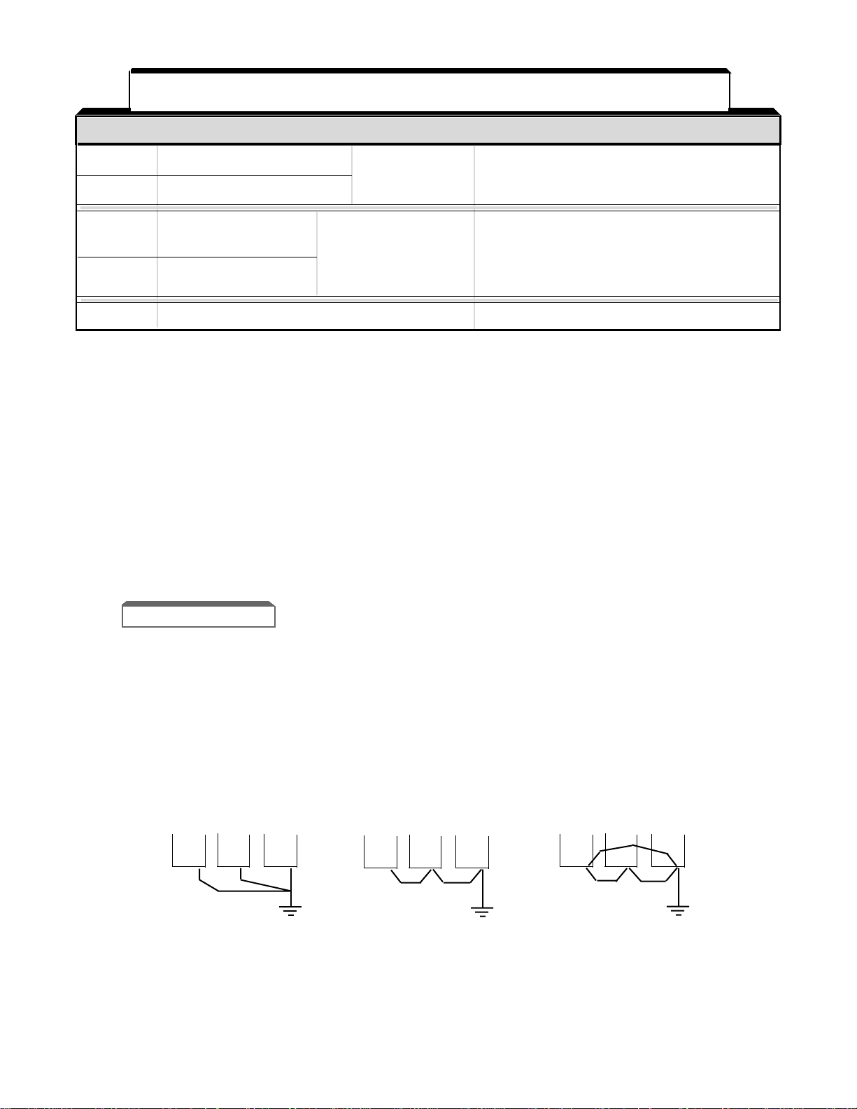
•• •
•
•• •
•• •
CORRECT CORRECT NOT
ACCEPTABLE
TERMINAL FUNCTIONS LEVELS
21 Multi-function analog monitor (+) Output current or Type of analog signal (operating parameter) to be
output frequency output is selected by setting of constant bn-13.
22 Multi-function analog monitor (-) is selectable Monitor output: 0 to +11V; 2 mA maximum
25 Multi-function open One of 18 functions Photocoupler insulation output: +48V, 50mA
collector output 1 are available, by or less
setting of system
26 Multi-function open constants Sn-21
collector output 2 and Sn-22.
27 Multi-function open collector output common 0V
TERMINAL FUNCTIONS LEVELS
NOTES:
1. When Forward Run and Reverse Run inputs are both closed for more than 500 ms, the Digital
Operator flashes “
EF
” and the motor (if rotating) is decelerated by the GPD 503 to a stop. This stop
condition is not stored by the GPD 503 (on Digital Operator, red lamp at STOP key does not light);
IF ONE OF THE INPUTS IS OPENED, THE MOTOR WILL IMMEDIATELY START UP
AGAIN.
2. Terminals 1-8 source +24 Vdc and operate in a Low = True (ON) configuration when connected to
terminal 11.
When using relays for input to terminals 1-8, use relays with highly reliable contacts (for very small
current) with a capacity of 30 Vdc or more and rated current of 100mA or higher. When using
transistor (open collector) input, use transistors with rated voltage of 35 Vdc or more and rated
current of 100mA or more.
Table 1-3. Terminal Functions and Signals of Control Circuit - Continued
1-6
1.4.3 Grounding
• The GPD 503 must be solidly grounded using main circuit ground terminal G (E).
Ground resistance should be 100 ohms or less. Select lead size suitable for size
of terminal screw. Make the length as short as possible.
• NEVER ground the GPD 503 in common with welding machines, motors, or
other large-current electrical equipment.
• Where several GPD 503s are used, ground each directly or daisy-chain to the
ground pole(s). DO NOT FORM A LOOP WITH THE GROUND LEADS.

1.4 ELECTRICAL INSTALLATION Continued
1.4.4 Auxiliary Input and Output Power Option Devices
Figure 1-2 is a factory guideline for proper wiring practices and relative locations within
the electrical path from the line to the load. It does not imply what devices are needed for
a particular application, nor does it show what devices were shipped with a particular
order. Therefore, disregard those items in the diagram which are not being used in your
installation.
Mount all power option devices as close to the drive, and keep electrical connections as
short as possible.
DO NOT run input and output wiring in the same conduit.
ISOLATION
TRANSFORMER
INPUT
REACTOR
INPUT
RFI FILTER
L3
L2
L1
H3
H2
H1
X3
X2
X1
C1
B1
A1
C2
B2
A2
C1(L3)
B1(L2)
A1(L1)
(L3)C2
(L2)B2
(L1)A2
L
I
N
E
L
O
A
D
CUSTOMER'S
3Ø A.C. LINE
POWER
SUPPLY
EARTH GROUND
SEE NOTE 2
(G)
RF NOISE
FILTER
SEE NOTE 5
SEE NOTE 3
L3
L2
L1
T3
T2
T1
INPUT
OUTPUT
MagneTek Drive
GND
EARTH GROUND
SEE NOTE 1
SEE NOTES 3, 4
OUTPUT
REACTOR
OUTPUT
RFI FILTER
TO CASE
EARTH
GROUND
SEE NOTE 2
SEE NOTES 3, 4
SEE NOTES 3, 4
A.C. MOTOR
1
2
3
4
5
6
IN
OUT
T3
T2
T1
C1
B1
A1
C2
B2
A2
EARTH GROUND
SEE NOTE 2
SEE NOTE 6
Figure 1-2. Customer Connection Diagram For Isolation Transformers,
Input Reactors, Input RFI Filters, Output Reactors and Output RFI FIlters
1-7
NOTES
1. Connect drive ground terminal or panel to
earth ground. Always use low impedance
paths and connections.
2. Mount input and output RFI filters
physically
as
close to the drive as possible (on the same
panel, if possible). Filters should have a solid
connection from filter case or ground terminal
to drive panel or ground terminal (conduit with
good bare metal to bare metal connections
may serve as the path). If multiple input or
output RFI filters are used, they must be wired
in parallel.
3. Shield conductors with metallic conduit.
4. Connect output conduit in a manner that
allows it to act as an unbroken shield from the
drive panel to the motor casing.
5. RF noise filter (different from RFI filter) part
no. 05P00325-0023 is a delta wye capacitor
network which is wired in parallel with the
drive input terminals. On the smaller drives
with die cast chassis, it must be mounted
externally. On the larger drives with sheet
metal chassis, it may be mounted inside the
area where the input power wiring enters the
drive. On units equipped with bypass, it may
be wired to the primary side of the circuit
breaker and mounted to the bypass panel or
sidewall.
6. Connection points:
Drive w/o Bypass Drive w/ Bypass
Input
L1, L2, L3
Ckt Brkr
L
1,
L
2,
L
3
Output
T1, T2, T3
Unwired side of
Overload relay

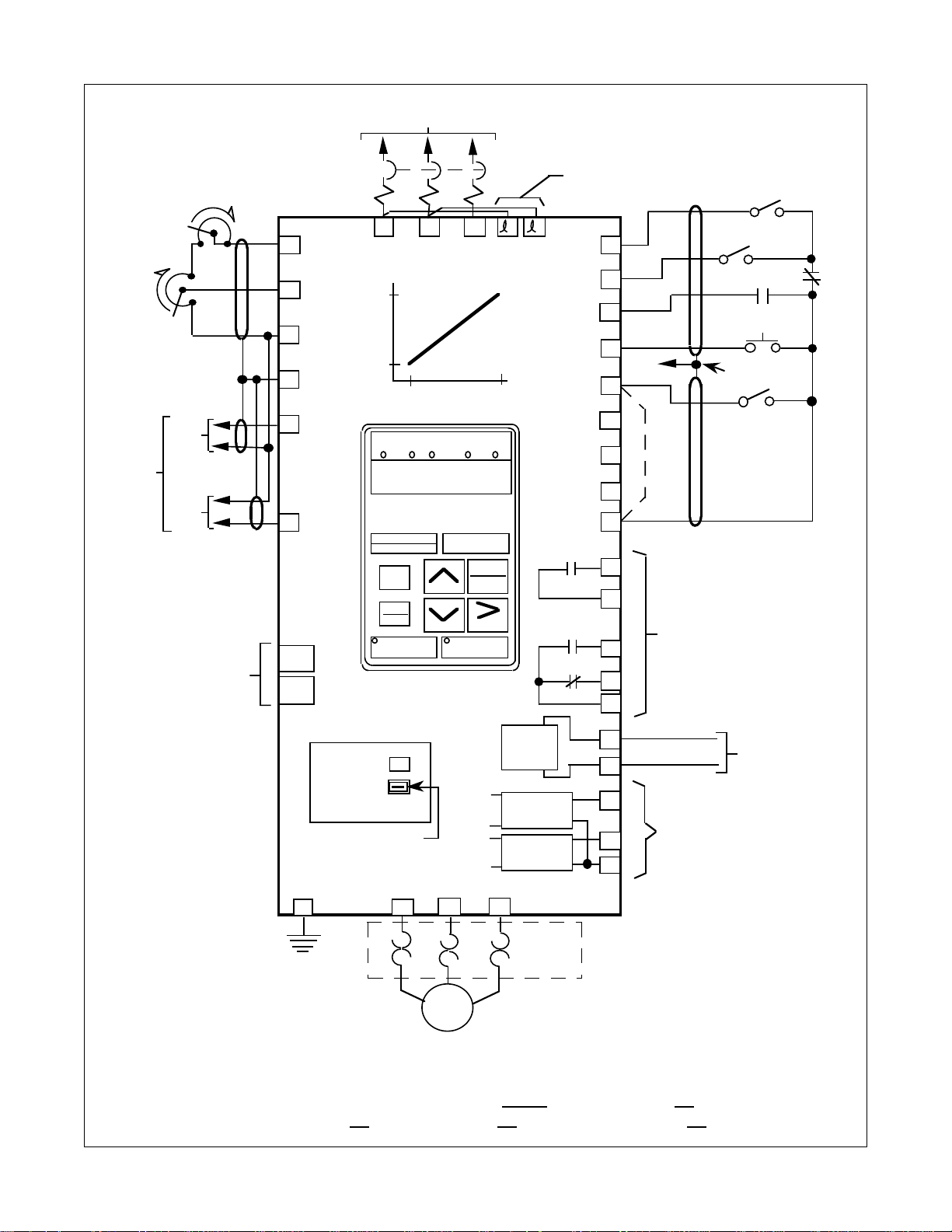
NOTES FOR FIGURE 1-3
✱ – Indicates components not supplied.
■ – Indicates customer connection terminal. Wire only to terminals shown.
( ) – Indicates alternate terminal marking, i.e., (R) and L1.
▲ – Function labels shown for these terminals are determined by factory settings of System Constants
Sn–15 through Sn-18.
● – Function labels shown for these terminals are determined by factory settings of System Constants
Sn–20 through Sn-22.
■ – Function labels shown for these terminals are determined by factory setting of System Constant
Sn-05 ( X X X X ).
– Function label shown for this terminal is determined by factory setting of System Constant Sn-19.
1. If only a remote Manual Speed pot (1RH) is used, 3SS is not needed; in that case, a jumper must be
added between terminals 5 and 11. This jumper will override both the Auto and Digital Operator
frequency references, regardless of the programming of Sn-04 X X X X. If you are using a remote speed
command or the Digital Operator, DO NOT install this jumper.
2. The GPD 503 Electronic Thermal Overload function (Sn-17, Cn-09) meets standards set by UL and CSA
for motor thermal overload protection. If local code requires separate mechanical overload protection,
an overload relay should be installed, interlocked with the GPD 503 as shown. It should be the manual
reset type to prevent automatic restart following a motor fault and subsequent contact reclosure after
cool down.
3. Insulated twisted shielded wire is required.
2-conductor #18 GA. (Beldon #8760 or equivalent).
3-conductor #18 GA. (Beldon #8770 of equivalent).
Connect shield ONLY AT GPD 503 END. Stub and isolate other end.
4. Digital Operator is standard on every GPD 503. Remote operators, as shown, may not be required.
5. Customer to connect terminal G (E) to earth ground.
6. Wire only one Auto Reference input.
7. If the Dynamic Braking (DB) option is used, wire per Appendix 7 instructions.
1-8

1-9
3ø POWER SUPPLY (SEE NAMEPLATE DATA)
1CB ✱
GPD 503
L1 L2 L3
15
16
17
12
14
13
V/HZ PROFILE
+15Vdc
(20mA MAX)
MAN REF. IN
(0 TO 10Vdc)
FWD
▲
▲
▲
▲
▲
▲
●
●
●
FWD
RUN/STOP
OUTPUT
VOLTAGE
(%)
COM
SHIELD
4-20mA
(250
OUTPUT FREQUENCY
(HZ)
DIGITAL
OPERATOR
PRGM
DRIVE
DATA
ENTER
0 TO 10Vdc
(20K
SEE
NOTE 4
REMOTE
DRIVE FWD REV SEQ REF
DSPL
4-20mA
0-10V
ISOLATED
AUTO
REFERENCE ✱
SEE NOTE 6
1OL ✱
SEE
NOTE 2
EXT. FAULT ✱
EXT. FAULT RESET
1PB ✱
SEE
NOTE 3
TO
TERM. 12
JOG
1R ✱
2K
MAN SPEED
1RH ✱
2K / 2.5K
SEE NOTE 1
AUTO
MAN
3SS ✱
1SS ✱
SEE
NOTE 1
1
2
3
4
5
6
7
8
11
9
REV
EXT. FAULT
FAULT RESET
AUTO/MAN
MULTI-STEP FREQ
SELECT
JOG
SPEED
COAST STOP
(BASE BLOCK)
0 VOLTS
RUN CONTACT
RY1
10
FAULT
CONTACTS
RY2
RY2
18
19
20
ANALOG
OUTPUT
(0-10 Vdc)
OPEN
COLLECTOR
CIRCUIT
OPEN
COLLECTOR
CIRCUIT
21
22
25
26
27
RESET
FWD
REV
RUN
STOP
RY CONTACTS
CAPACITY:
1A AT 250Vac
1A AT 30Vdc
MULTI-FUNCTION
MONITOR OUTPUT
0 - +10V
2mA MAX.
MULTI-
FUNCTION
OPEN
COLLECTOR
OUTPUTS
CAPACITY:
50mA AT 48Vdc MAX.
AC MOTOR ✱
(T2)
(T1) (T3)
G
T1 T2 T3
200V 380V 440V
220/ 400/ 460V
230V 415V
VOLTAGE SELECTOR
(460V, 15HP (CT) AND ABOVE)
FACTORY SET FOR 460V
EARTH
GROUND
SEE NOTE 5
1OL ✱
SEE NOTE 2
L1 L2 L3
GPD 503 BASIC INTERCONNECT DIAGRAM FOR 2-WIRE CONTROL
(R) (S) (T)
(E)
(U) (V) (W)
2SS ✱
REV
RUN/STOP
■
TERMINALS 1-8:
IF INPUT FROM RELAY CONTACTS:
RATED 30Vdc OR MORE,
100mA OR MORE
IF OPEN COLLECTOR INPUT:
RATED 35Vdc OR MORE,
100mA OR MORE
B1 or
B0/–
B2 or
B1/+
FOR WIRING
DYNAMIC
BRAKING
OPTION
SEE NOTE 7
1
2
COOLING
FAN
POWER
(15HP (CT) AND ABOVE)
Figure 1-3. 230V or 460V Interconnections - 2-Wire Control
(with constant Sn-04 set to 0000, Sn-15 set to 03,
Sn-16 set to 04, Sn-17 set to 06, and Sn-18 set to 08 )
FOR UNITS
WITH "L" IN
MODEL NO.
( "L" ) (04/27/95)
– (N)
+3
(P3)

NOTES FOR FIGURE 1-4
✱ – Indicates components not supplied.
■ – Indicates customer connection terminal. Wire only to terminals shown.
( ) – Indicates alternate terminal marking, i.e., (R) and L1.
▲ – Function labels shown for these terminals are determined by 3-Wire Control settings of System
Constants Sn-16 through Sn-18: Sn-16 =
03
, Sn-17 =
04
, Sn-18 =
06
.
● – Function labels shown for these terminals are determined by factory settings of System Constants
Sn–20 through Sn-22.
■ – Function labels shown for these terminals are determined by factory setting of System Constant
Sn-05 ( X X X X ).
– Function label shown for this terminal is determined by factory setting of System Constant Sn-19.
1. If only a remote Manual Speed pot (1RH) is used, 2SS is not needed; in that case, a jumper must be
added between terminals 6 and 11. This jumper will override both the Auto and Digital Operator
frequency references, regardless of the programming of Sn-04 X X X X. If you are using a remote speed
command or the Digital Operator, DO NOT install this jumper.
2. The GPD 503 Electronic Thermal Overload function (Sn-17, Cn-09) meets standards set by UL and CSA
for motor thermal overload protection. If local code requires separate mechanical overload protection,
an overload relay should be installed, interlocked with the GPD 503 as shown. It should be the manual
reset type to prevent automatic restart following a motor fault and subsequent contact reclosure after
cool down.
3. Insulated twisted shielded wire is required.
2-conductor #18 GA. (Beldon #8760 or equivalent).
3-conductor #18 GA. (Beldon #8770 or equivalent).
Connect shield ONLY AT GPD 503 END. Stub and isolate other end.
4. Digital Operator is standard on every GPD 503. Remote operators, as shown, may not be required.
5. Customer to connect terminal G (E) to earth ground.
6. Wire only one Auto Reference input.
7. If the Dynamic Braking (DB) option is used, wire per Appendix 7 instructions.
CAUTION
Before running, Sn-03 must be set to "0000".
Resetting drive constant Sn-03 to "1110" may cause
the motor to run in the reverse direction WITHOUT A
RUN COMMAND, and possibly result in damage to the
equipment or personal injury.
1-10

1-11
3ø POWER SUPPLY (SEE NAMEPLATE DATA)
1CB ✱
GPD 503
L1 L2 L3
15
16
17
12
14
13
V/HZ PROFILE
+15Vdc
(20mA MAX)
MAN REF. IN
(0 TO 10Vdc)
RUN
▲
▲
▲
▲
▲
●
●
●
RUN
1PB ✱
OUTPUT
VOLTAGE
(%)
COM
SHIELD
4-20mA
(250
OUTPUT FREQUENCY
(HZ)
DIGITAL
OPERATOR
PRGM
DRIVE
DATA
ENTER
0 TO 10Vdc
(20K
SEE
NOTE 4
REMOTE
DRIVE FWD REV SEQ REF
DSPL
4-20mA
0-10V
ISOLATED
AUTO
REFERENCE ✱
SEE NOTE 6
STOP
2PB ✱
1OL ✱
SEE
NOTE 2
EXT. FAULT ✱
EXT. FAULT RESET
3PB ✱
SEE
NOTE 3
TO
TERM. 12
JOG
1R ✱
2K
MAN SPEED
1RH ✱
2K / 2.5K
SEE NOTE 1
AUTO
MAN
2SS ✱
1SS ✱
FWD
REV
SEE
NOTE 1
1
2
3
4
5
6
7
8
11
9
STOP
EXT. FAULT
FAULT RESET
AUTO/MAN
MULTI-STEP
FREQ
SELECT
JOG
SPEED
FWD/REV
0 VOLTS
RUN CONTACT
RY1
10
FAULT
CONTACTS
RY2
RY2
18
19
20
ANALOG
OUTPUT
(0-10 Vdc)
OPEN
COLLECTOR
CIRCUIT
OPEN
COLLECTOR
CIRCUIT
21
22
25
26
27
RESET
FWD
REV
RUN
STOP
RY CONTACTS
CAPACITY:
1A AT 250Vac
1A AT 30Vdc
MULTI-FUNCTION
MONITOR OUTPUT
0 - +10V
2mA MAX.
MULTI-
FUNCTION
OPEN
COLLECTOR
OUTPUTS
CAPACITY:
50mA AT 48Vdc MAX.
AC MOTOR ✱
(T2)
(T1) (T3)
G
T1 T2 T3
200V 380V 440V
220/ 400/ 460V
230V 415V
VOLTAGE SELECTOR
(460V, 15HP (CT) AND ABOVE)
FACTORY SET FOR 460V
EARTH
GROUND
SEE NOTE 5
1OL ✱
SEE NOTE 2
L1 L2 L3
GPD 503 BASIC INTERCONNECT DIAGRAM FOR 3-WIRE CONTROL
(R) (S) (T)
(E)
(U) (V) (W)
■
TERMINALS 1-8:
IF INPUT FROM RELAY CONTACTS:
RATED 30Vdc OR MORE,
100mA OR MORE;
IF OPEN COLLECTOR INPUT:
RATED 35Vdc OR MORE,
100mA OR MORE
FOR WIRING
DYNAMIC
BRAKING
OPTION
SEE NOTE 7
B1 or
B0/–
B2 or
B1/+
1
2
COOLING
FAN
POWER
(15HP (CT) AND ABOVE)
Figure 1-4. 230V or 460V Interconnections - 3-Wire Control
(with constant Sn-04 set to 0000, Sn-15 set to 00,
Sn-16 set to 03, Sn-17 set to 04, and Sn-18 set to 06 )
( "L" ) (04/27/95)
FOR UNITS
WITH "L" IN
MODEL NO.
– (N)
+3
(P3)

1-12
NOTES FOR FIGURE 1-5
✱ – Indicates components not supplied.
■ – Indicates customer connection terminal. Wire only to terminals shown.
( ) – Indicates alternate terminal marking, i.e., (R) and L1.
▲ – Function labels shown for these terminals are determined by factory settings of System Constants
Sn–15 through Sn-18.
● – Function labels shown for these terminals are determined by factory settings of System Constants
Sn–20 through Sn-22.
■ – Function labels shown for these terminals are determined by factory setting of System Constant
Sn-05 ( X X X X ).
– Function label shown for this terminal is determined by factory setting of System Constant Sn-19.
1. If only a remote Manual Speed pot (1RH) is used, 3SS is not needed; in that case, a jumper must be
added between terminals 5 and 11. This jumper will override both the Auto and Digital Operator
frequency references, regardless of the programming of Sn-04 X X X X. If you are using a remote speed
command or the Digital Operator, DO NOT install this jumper.
2. The GPD 503 Electronic Thermal Overload function (Sn-17, Cn-09) meets standards set by UL and CSA
for motor thermal overload protection. If local code requires separate mechanical overload protection,
an overload relay should be installed, interlocked with the GPD 503 as shown. It should be the manual
reset type to prevent automatic restart following a motor fault and subsequent contact reclosure after
cool down.
3. Insulated twisted shielded wire is required.
2-conductor #18 GA. (Beldon #8760 or equivalent).
3-conductor #18 GA. (Beldon #8770 of equivalent).
Connect shield ONLY AT GPD 503 END. Stub and isolate other end.
4. Digital Operator is standard on every GPD 503. Remote operators, as shown, may not be required.
5. Customer to connect terminal G (E) to earth ground.
6. Wire only one Auto Reference input.
7. If the Dynamic Braking (DB) option is used, wire per Appendix 7 instructions.
1-13
3ø POWER SUPPLY (SEE NAMEPLATE DATA)
1CB ✱
GPD 503
L1 L2 L3
15
16
17
12
14
13
V/HZ PROFILE
+15Vdc
(20mA MAX)
MAN REF. IN
(0 TO 10Vdc)
FWD
▲
▲
▲
▲
▲
▲
●
●
●
FWD
RUN/STOP
OUTPUT
VOLTAGE
(%)
COM
SHIELD
4-20mA
(250
OUTPUT FREQUENCY
(HZ)
DIGITAL
OPERATOR
PRGM
DRIVE
DATA
ENTER
0 TO 10Vdc
(20K
SEE
NOTE 4
REMOTE
DRIVE FWD REV SEQ REF
DSPL
4-20mA
0-10V
ISOLATED
AUTO
REFERENCE ✱
SEE NOTE 6
1OL ✱
SEE
NOTE 2
EXT. FAULT ✱
EXT. FAULT RESET
1PB ✱
SEE
NOTE 3
TO
TERM. 12
JOG
1R ✱
2K
MAN SPEED
1RH ✱
2K / 2.5K
SEE NOTE 1
AUTO
MAN
3SS ✱
1SS ✱
SEE
NOTE 1
1
2
3
4
5
6
7
8
11
9
REV
EXT. FAULT
FAULT RESET
AUTO/MAN
MULTI-STEP FREQ
SELECT
JOG
SPEED
COAST STOP
(BASE BLOCK)
0 VOLTS
RUN CONTACT
RY1
10
FAULT
CONTACTS
RY2
RY2
18
19
20
ANALOG
OUTPUT
(0-10 Vdc)
OPEN
COLLECTOR
CIRCUIT
OPEN
COLLECTOR
CIRCUIT
21
22
25
26
27
RESET
FWD
REV
RUN
STOP
RY CONTACTS
CAPACITY:
1A AT 250Vac
1A AT 30Vdc
MULTI-FUNCTION
MONITOR OUTPUT
0 - +10V
2mA MAX.
MULTI-
FUNCTION
OPEN
COLLECTOR
OUTPUTS
CAPACITY:
50mA AT 48Vdc MAX.
AC MOTOR ✱
(T2)
(T1) (T3)
G
T1 T2 T3
5000V
575/600V
VOLTAGE SELECTOR
(15HP AND ABOVE)
FACTORY SET FOR 575/600V
EARTH
GROUND
SEE NOTE 5
1OL ✱
SEE NOTE 2
L1 L2 L3
GPD 503 BASIC INTERCONNECT DIAGRAM FOR 2-WIRE CONTROL
(R) (S) (T)
(E)
(U) (V) (W)
2SS ✱
REV
RUN/STOP
■
TERMINALS 1-8:
IF INPUT FROM RELAY CONTACTS:
RATED 30Vdc OR MORE,
100mA OR MORE
IF OPEN COLLECTOR INPUT:
RATED 35Vdc OR MORE,
100mA OR MORE
B1 or
B0/–
B2 or
B1/+
FOR WIRING
DYNAMIC
BRAKING
OPTION
SEE NOTE 7
12
COOLING
FAN
POWER
(15HP AND ABOVE)
Figure 1-5. 575V Interconnections - 2-Wire Control
(with constant Sn-04 set to 0000, Sn-15 set to 03,
Sn-16 set to 04, Sn-17 set to 06, and Sn-18 set to 08 )

1-14
NOTES FOR FIGURE 1-6
✱ – Indicates components not supplied.
■ – Indicates customer connection terminal. Wire only to terminals shown.
( ) – Indicates alternate terminal marking, i.e., (R) and L1.
▲ – Function labels shown for these terminals are determined by 3-Wire Control settings of System
Constants Sn-16 through Sn-18: Sn-16 =
03
, Sn-17 =
04
, Sn-18 =
06
.
● – Function labels shown for these terminals are determined by factory settings of System Constants
Sn–20 through Sn-22.
■ – Function labels shown for these terminals are determined by factory setting of System Constant
Sn-05 ( X X X X ).
– Function label shown for this terminal is determined by factory setting of System Constant Sn-19.
1. If only a remote Manual Speed pot (1RH) is used, 2SS is not needed; in that case, a jumper must be
added between terminals 6 and 11. This jumper will override both the Auto and Digital Operator
frequency references, regardless of the programming of Sn-04 X X X X. If you are using a remote speed
command or the Digital Operator, DO NOT install this jumper.
2. The GPD 503 Electronic Thermal Overload function (Sn-17, Cn-09) meets standards set by UL and CSA
for motor thermal overload protection. If local code requires separate mechanical overload protection,
an overload relay should be installed, interlocked with the GPD 503 as shown. It should be the manual
reset type to prevent automatic restart following a motor fault and subsequent contact reclosure after
cool down.
3. Insulated twisted shielded wire is required.
2-conductor #18 GA. (Beldon #8760 or equivalent).
3-conductor #18 GA. (Beldon #8770 or equivalent).
Connect shield ONLY AT GPD 503 END. Stub and isolate other end.
4. Digital Operator is standard on every GPD 503. Remote operators, as shown, may not be required.
5. Customer to connect terminal G (E) to earth ground.
6. Wire only one Auto Reference input.
7. If the Dynamic Braking (DB) option is used, wire per Appendix 7 instructions.
CAUTION
Before running, Sn-03 must be set to "0000".
Resetting drive constant Sn-03 to "1110" may cause
the motor to run in the reverse direction WITHOUT A
RUN COMMAND, and possibly result in damage to the
equipment or personal injury.
Loading...