


 Loading...
™
MP2600iec
Hardware Manual

Table of Contents
Table of Contents
1 Introduction
1.1 MP2600iec Features - - - - - - - - - - - - - - - - - - - - - - - - 3
1.2 MP2600iec Appearance- - - - - - - - - - - - - - - - - - - - - - 4
1.3 Model Number Reference - - - - - - - - - - - - - - - - - - - - 5
2 Specifications
2.1 General Specifications - - - - - - - - - - - - - - - - - - - - - - - 7
2.2 MP2600iec Hardware Specifications - - - - - - - - - - - - - 8
3 Mechanical Installation
3.1 Mounting Information- - - - - - - - - - - - - - - - - - - - - - - - 9
3.2 Installation Standards - - - - - - - - - - - - - - - - - - - - - - 10
3.3 Dimensions- - - - - - - - - - - - - - - - - - - - - - - - - - - - - - 11
4 Inputs/Outputs
4.1 CN13 Connection Diagram - - - - - - - - - - - - - - - - - - 13
4.2 CN13 Connection Description - - - - - - - - - - - - - - - - 14
4.3 External Encoder Interface - - - - - - - - - - - - - - - - - - 15
4.4 Controller Digital I/O - - - - - - - - - - - - - - - - - - - - - - - 16
4.5 Sigma-5 I/O - - - - - - - - - - - - - - - - - - - - - - - - - - - - - 18
4.6 Analog I/O - - - - - - - - - - - - - - - - - - - - - - - - - - - - - - 19
5 |
DIP Switches |
|
|
|
5.1 |
Switch Settings - - - - - - - - - - - - - - - - - - - - - - - - - - - |
21 |
6 LED Outputs - - - - - - - - - - - - - - - - - - - - - - - - - - - - - - - |
23 |
||
7 |
Battery |
|
|
|
7.1 |
Battery Installation- - - - - - - - - - - - - - - - - - - - - - - - - |
25 |
1

Table of Contents
8 Ethernet
8.1 Connectivity Information- - - - - - - - - - - - - - - - - - - - - 27
8.2 Ethernet Connector Details- - - - - - - - - - - - - - - - - - - 27
8.3 Ethernet Cable - - - - - - - - - - - - - - - - - - - - - - - - - - - 28
8.4 Ethernet Connection Examples- - - - - - - - - - - - - - - - 28
9 Cable Diagrams
9.1 CBK-U-MP2B-xx (Terminal Block-Controller) - - - - - - 31
9.2 CFC-U-MP2B-xx (Flying Lead-Controller) - - - - - - - - 32
9.3 SBK-U-VBA-xx (Terminal Block-Servo Amp) - - - - - - 33
9.4 JZSP-CSI02-x-E (Flying Lead-Servo Amp) - - - - - - - 34
10 Firmware Upgrade Procedure - - - - - - - - - - - - - - - - - 35
11 EMC Installation Conditions - - - - - - - - - - - - - - - - - - 37
2

1.1 MP2600iec Features
1 Introduction
1.1 MP2600iec Features
MP2600iec is a single-axis machine controller option card that is attached to a Sigma-5 servo amplifier. The servo amplifier and controller are factory assembled, providing a compact, all-in-one servo/controller package with the following features:
PLCopen for Motion Control, including indexing, camming, gearing, and servo parameter maintenance capability.
Sigma-5 self-tuning, anti-vibration, and other high performance, easy-to-implement servo control features
Ethernet (100Mbps) Auto crossover switching
•EtherNet/IP
•Modbus TCP
•Allows high-speed communications with MotionWorks IEC
•Enables communication with the application program by using a touch panel
•Enables communication with the application program from another controller
Combined Amplifier/Controller I/O features
•15 digital inputs
•11 digital outputs
•1 analog input
•1 analog output
•1 external encoder (quadrature, pulse + direction, up/down)
•1 external encoder latch
3
1.2 MP2600iec Appearance
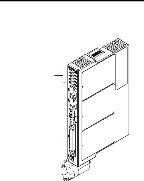
1.2 MP2600iec Appearance
The following figure shows the external appearance of the MP2600iec controller (Note: The servo amplifier is not shown).
LED (10 points)
Ethernet Port A 


Ethernet Port B 


DIP Switch (6 points) 


CN13 Port
Analog I/O, Digital I/O
External Encoder (incremental)
3.6V Lithium Battery 
 (preserves retained variables,


absolute encoder offset, and real-time clock data)
4
1.3 Model Number Reference
1.3.1 Model Number Designation
1.3 Model Number Reference
1.3.1Model Number Designation
|
|
|
SGDV |
|
|
R70 |
|
A E 1 A |
000 |
00 |
0 |
300 |
|
||||||||||||||||||||||||
|
|
|
|
|
|
|
|
|
|
|
|
|
|
|
|
|
|
|
|
|
|
|
|
|
|
|
|
|
|
|
|
|
|
|
|
|
|
|
Series SGDV SERVOPACK |
|
|
|
|
|
|
|
|
|
|
|
|
|
|
|
|
|
|
|
|
|
|
Option Module |
|||||||||||||
|
Current |
|
|
|
|
|
|
|
|
|
|
|
|
|
|
|
|
|
|
|
|
|
|
|
|
|
|
|
|
|
|
|
Code |
|
|
Specifications |
|
|
|
|
|
|
|
|
|
|
|
|
|
|
|
|
|
|
|
|
|
|
|
|
|
|
|
|
|
|
|
|
|
|
300 |
|
|
|
MP2600iec 1.5 Axis |
|
Voltage |
Code |
Applicable Servomotor |
|
|
|
|
|
|
|
|
|
|
|
|
|
|
|
|
|
|
|
|
|
|
|
|
|
|
Machine Controller |
|||||||
|
|
Max. Capacity kW |
|
|
|
|
|
|
|
|
|
|
|
|
|
|
|
|
|
|
|
|
|
|
|
|
|
|
|
Module |
|||||||
|
|
|
|
|
|
|
|
|
|
|
|
|
|
|
|
|
|
|
|
|
|
|
|
|
|
|
|
|
|
|
|
||||||
|
|
R70 |
|
|
0.05 |
|
|
|
|
|
|
|
|
|
|
|
|
|
|
|
|
|
|
|
|
|
|
|
|
|
Options (parameter) |
||||||
|
100V |
R90 |
|
|
0.1 |
|
|
|
|
|
|
|
|
|
|
|
|
|
|
|
|
|
|
|
|
|
|
|
|
|
|||||||
|
|
|
|
|
|
|
|
|
|
|
|
|
|
|
|
|
|
|
|
|
|
|
|
|
|
|
|
||||||||||
|
|
2R1 |
|
|
0.2 |
|
|
|
|
|
|
|
|
|
|
|
|
|
|
|
|
|
|
|
|
|
|
|
|
|
Code |
|
|
Specifications |
|||
|
|
|
|
|
|
|
|
|
|
|
|
|
|
|
|
|
|
|
|
|
|
|
|
|
|
|
|
|
|
|
0 |
|
|
|
standard |
||
|
|
2R8 |
|
|
0.4 |
|
|
|
|
|
|
|
|
|
|
|
|
|
|
|
|
|
|
|
|
|
|
|
|
|
|
|
|
||||
|
|
|
|
|
|
|
|
|
|
|
|
|
|
|
|
|
|
|
|
|
|
|
|
|
|
|
|
|
|
|
|
|
|
|
|
||
|
|
R70* |
|
|
0.05 |
|
|
|
|
|
|
|
|
|
|
|
|
|
|
|
|
|
|
|
|
|
|
|
|
|
Options (software) |
||||||
|
|
R90* |
|
|
0.1 |
|
|
|
|
|
|
|
|
|
|
|
|
|
|
|
|
|
|
|
|
|
|
|
|
|
|||||||
|
|
|
|
|
|
|
|
|
|
|
|
|
|
|
|
|
|
|
|
|
|
|
|
|
|
|
|
|
|||||||||
|
|
|
|
|
|
|
|
|
|
|
|
|
|
|
|
|
|
|
|
|
|
|
|
|
|
|
|
|
|
|
|
|
|
||||
|
|
1R6* |
|
|
0.2 |
|
|
|
|
|
|
|
|
|
|
|
|
|
|
|
|
|
|
|
|
|
|
|
|
|
Code |
|
|
Specifications |
|||
|
|
|
|
|
|
|
|
|
|
|
|
|
|
|
|
|
|
|
|
|
|
|
|
|
|
|
|
|
|
|
00 |
|
|
standard |
|||
|
|
2R8* |
|
|
0.4 |
|
|
|
|
|
|
|
|
|
|
|
|
|
|
|
|
|
|
|
|
|
|
|
|
|
|
|
|||||
|
|
|
|
|
|
|
|
|
|
|
|
|
|
|
|
|
|
|
|
|
|
|
|
|
|
|
|
|
|
|
|
|
|
|
|
||
|
|
3R8 |
|
|
0.5 |
|
|
|
|
|
|
|
|
|
|
|
|
|
|
|
|
|
|
|
|
|
|
|
|
|
Options (hardware) |
||||||
|
|
5R5* |
|
|
0.75 |
|
|
|
|
|
|
|
|
|
|
|
|
|
|
|
|
|
|
|
|
|
|
|
|
|
|||||||
|
|
|
|
|
|
|
|
|
|
|
|
|
|
|
|
|
|
|
|
|
|
|
|
|
|
|
|
||||||||||
|
|
7R6 |
|
|
1.0 |
|
|
|
|
|
|
|
|
|
|
|
|
|
|
|
|
|
|
|
|
|
|
|
|
|
Code |
|
|
Specifications |
|||
|
|
|
|
|
|
|
|
|
|
|
|
|
|
|
|
|
|
|
|
|
|
|
|
|
|
|
|
|
000 |
|
|
Base-mounted |
|||||
|
200V |
120 ♣ |
|
|
1.5 |
|
|
|
|
|
|
|
|
|
|
|
|
|
|
|
|
|
|
|
|
|
|
|
|
|
|
|
|||||
|
|
|
|
|
|
|
|
|
|
|
|
|
|
|
|
|
|
|
|
|
|
|
|
|
|
|
|
|
|
|
|
(standard) |
|||||
|
|
180 |
|
|
2.0 |
|
|
|
|
|
|
|
|
|
|
|
|
|
|
|
|
|
|
|
|
|
|
|
|
|
|
|
|
|
|||
|
|
|
|
|
|
|
|
|
|
|
|
|
|
|
|
|
|
|
|
|
|
|
|
|
|
|
|
|
|
|
|
|
|
||||
|
|
|
|
|
|
|
|
|
|
|
|
|
|
|
|
|
|
|
|
|
|
|
|
|
|
|
|
|
|
|
|
|
|
||||
|
|
200 |
|
|
3.0 |
|
|
|
|
|
|
|
|
|
|
|
|
|
|
|
|
|
|
|
|
|
|
|
|
|
Design Revision Order |
||||||
|
|
|
|
|
|
|
|
|
|
|
|
|
|
|
|
|
|
|
|
|
|
|
|
|
|
|
|
|
|
|
|
|
|||||
|
|
330 |
|
|
5.0 |
|
|
|
|
|
|
|
|
|
|
|
|
|
|
|
|
|
|
|
|
|
|
|
|
|
A, B… |
||||||
|
|
470 |
|
|
6.0 |
|
|
|
|
|
|
|
|
|
|
|
|
|
|
|
|
|
|
|
|
|
|
|
|
Motor Type |
|||||||
|
|
550 |
|
|
7.5 |
|
|
|
|
|
|
|
|
|
|
|
|
|
|
|
|
|
|
|
|
|
|
|
|
||||||||
|
|
|
|
|
|
|
|
|
|
|
|
|
|
|
|
|
|
|
|
|
|
|
|
|
|
|
|
||||||||||
|
|
590 |
|
|
11 |
|
|
|
|
|
|
|
|
|
|
|
|
|
|
|
|
|
|
|
|
|
|
|
|
|
|
|
|
|
|||
|
|
|
|
|
|
|
|
|
|
|
|
|
|
|
|
|
|
|
|
|
|
|
|
|
|
|
|
|
Code |
|
|
Specifications |
|||||
|
|
780 |
|
|
15 |
|
|
|
|
|
|
|
|
|
|
|
|
|
|
|
|
|
|
|
|
|
|
|
|
|
1 |
|
Rotary Servomotors |
||||
|
|
1R9 |
|
|
0.5 |
|
|
|
|
|
|
|
|
|
|
|
|
|
|
|
|
|
|
|
|
|
|
|
|
|
5** |
|
Linear Servomotors |
||||
|
|
3R5 |
|
|
1.0 |
|
|
|
|
|
|
|
|
|
|
|
|
|
|
|
|
|
|
|
|
|
|
|
|
|
** Under Development |
||||||
|
|
5R4 |
|
|
1.5 |
|
|
|
|
|
|
|
|
|
|
|
|
|
|
|
|
|
|
|
|
|
|
|
|
Interface Options |
|||||||
|
|
8R4 |
|
|
2.0 |
|
|
|
|
|
|
|
|
|
|
|
|
|
|
|
|
|
|
|
|
|
|
|
|
||||||||
|
|
|
|
|
|
|
|
|
|
|
|
|
|
|
|
|
|
|
|
|
|
|
|
|
|
|
|||||||||||
|
|
|
|
|
|
|
|
|
|
|
|
|
|
|
|
|
|
|
|
|
|
|
|
|
|
|
|
|
|
|
|
|
|
||||
|
400V |
120 |
|
|
3.0 |
|
|
|
|
|
|
|
|
|
|
|
|
|
|
|
|
|
|
|
|
|
|
|
|
|
Code |
|
|
Specifications |
|||
|
170 |
|
|
5.0 |
|
|
|
|
|
|
|
|
|
|
|
|
|
|
|
|
|
|
|
|
|
|
|
|
|
E |
Communication Reference |
||||||
|
|
|
|
|
|
|
|
|
|
|
|
|
|
|
|
|
|
|
|
|
|
|
|
|
|
|
|
|
|||||||||
|
|
210 |
|
|
6.0 |
|
|
|
|
|
|
|
|
|
|
|
|
|
|
|
|
|
|
|
|
|
|
|
|
|
Voltage |
|
|
|
|||
|
|
260 |
|
|
7.5 |
|
|
|
|
|
|
|
|
|
|
|
|
|
|
|
|
|
|
|
|
|
|
|
|
|
|
|
|
||||
|
|
|
|
|
|
|
|
|
|
|
|
|
|
|
|
|
|
|
|
|
|
|
|
|
|
|
|
|
|
|
|
||||||
|
|
|
|
|
|
|
|
|
|
|
|
|
|
|
|
|
|
|
|
|
|
|
|
|
|
|
|
|
|
|
|
|
|
||||
|
|
280 |
|
|
11 |
|
|
|
|
|
|
|
|
|
|
|
|
|
|
|
|
|
|
|
|
|
|
|
|
|
Code |
|
|
Specifications |
|||
|
|
|
|
|
|
|
|
|
|
|
|
|
|
|
|
|
|
|
|
|
|
|
|
|
|
|
|
|
|
|
F |
|
|
100 VAC |
|||
|
|
370 |
|
|
15 |
|
|
|
|
|
|
|
|
|
|
|
|
|
|
|
|
|
|
|
|
|
|
|
|
|
|
|
|||||
|
|
|
|
|
|
|
|
|
|
|
|
|
|
|
|
|
|
|
|
|
|
|
|
|
|
|
|
|
|
|
|
|
A |
|
|
200 VAC |
|
* These amplifiers can be powered with single or three-phase. |
|
|
|
|
|
|
|
|
|
|
|
|
|
||||||||||||||||||||||||
|
|
|
|
|
|
|
|
|
|
|
D |
|
|
400 VAC |
|||||||||||||||||||||||
♣ SGDV-120A¡¡A008000¡¡¡, a special version of the 1.5kW |
|
|
|
|
|
|
|
|
|
|
|
|
|
||||||||||||||||||||||||
|
|
|
|
|
|
|
|
|
|
|
|
|
|
|
|
||||||||||||||||||||||
|
amplifier can be used for single-phase operation. |
|
|
|
|
|
|
|
|
|
|
|
|
|
|
|
|
|
|
|
|
|
|
|
|
|
|
|
|||||||||
5

1.3 Model Number Reference
1.3.2 Accessory Model Numbers
1.3.2Accessory Model Numbers
|
|
System Components |
|
|
||
|
|
|
|
|
|
|
Type |
Model |
Part Number |
|
|
Note |
|
|
|
|
|
|
||
|
Battery |
JZSP-BA01 |
Replacement |
|
||
|
|
|
|
|||
|
Battery Holder Kit |
SGDV-OZC02A |
Replacement (does not include battery) |
|||
|
|
|
|
|
|
|
Accessories/Cables |
CN13 (MP2600iec) |
|
|
|
|
|
Terminal Block |
CBK-U-MP2Bxx |
|
|
|
||
Conversion Kit |
|
xx denotes cable length (m) |
||||
|
|
|||||
|
|
|||||
CN13 (MP2600iec) |
CFC-U-MP2Bxx |
A5 = 0.5 |
|
|
||
(Flying Leads) |
01 = 1 |
|
|
|||
|
|
|
||||
|
|
03 = 3 |
|
|
||
CN1 (Servo Amp) |
|
|
|
|||
|
|
|
|
|||
Terminal Block |
SBK-U-MP2Bxx |
|
|
|
||
|
|
|
|
|||
|
Conversion Kit |
|
|
|
|
|
|
|
|
|
|||
|
CN1 (Servo Amp) Cable |
JZSP-CSI02-x-E |
x denotes cable length (m) |
|||
|
(Flying Leads) |
A = 1 |
B = 2 |
C = 3 |
||
|
|
|||||
|
|
|
|
|||
Communication |
Ethernet Cable |
N/A |
Use commonly available shielded Ethernet |
|||
cable |
|
|
||||
|
|
|
|
|||
|
|
|
|
|
||
|
|
|
|
|||
|
MotionWorks IEC |
PDE-U-IESx |
denotes MotionWorks IEC Version |
|||
Software |
Express |
C = 1 |
2 = 2 |
|
||
|
|
|||||
|
|
x denotes number of software licenses |
||||
MotionWorks IEC Pro |
PDE-U-IEPx |
|||||
A = 1 |
B = 5 |
C = 10 |
||||
|
|
|
|
|
||
OPC Server |
PDE-U-OPCPx |
x denotes number of software licenses |
||||
|
||||||
|
A = 1 B = 5 C = 10 D = 20 |
|||||
|
|
|
||||
|
|
|
|
|
|
|
6

2.1 General Specifications
2 Specifications
2.1 General Specifications
|
Item |
Specifications |
|
|
|
|
|
|
Ambient Operating |
0 to 55°C |
|
|
Temperature |
||
|
|
||
|
Ambient Storage |
-20°C to +85°C |
|
|
Temperature |
||
|
|
||
|
Ambient Operating |
90% RH or less (with no condensation) |
|
|
Humidity |
||
|
|
||
Environmental |
Ambient Storage |
90% RH or less (with no condensation) |
|
Humidity |
|||
Conditions |
|
||
|
Protection class: IP10, Pollution degree: 2 |
||
|
|
||
|
Protection Class/ |
An environment that satisfies the following conditions. |
|
|
• Free of corrosive or explosive gases |
||
|
Pollution Degree |
||
|
• Free of exposure to water, oil or chemicals |
||
|
|
||
|
|
• Free of dust, salts or iron dust |
|
|
|
|
|
|
Operating Altitude |
1,000 m above sea level or lower |
|
|
|
|
|
|
Vibration |
4.9 m/s2 |
|
|
Resistance |
||
|
|
||
Mechanical |
Shock Resistance |
19.6 m/s2 |
|
Operating |
|||
Conditions |
|
|
|
|
Others |
Free of static electricity, strong electromagnetic fields, |
|
|
magnetic fields or exposure to radioactivity |
||
|
|
||
|
|
|
7

2.2 MP2600iec Hardware Specifications
2.2 MP2600iec Hardware Specifications
Item |
|
|
|
Specification |
||
|
|
|
|
|
||
CPU |
|
|
|
200 MHz, 32 bit, ARM 9 |
||
|
|
|
|
|
|
|
|
|
SDRAM |
|
32 MB |
||
|
|
|
|
|||
Memory |
SRAM |
|
512 kB with battery backup |
|||
|
|
|
|
|
||
|
|
Flash |
|
4 MB flash. Code and parameter storage. |
||
|
|
|
|
|
|
|
|
|
LED |
|
10 LEDs (red and green - operating mode, |
||
|
|
|
communication and error status) |
|||
Operator interface |
|
|
|
|||
User Configuration |
6x DIP switch (operating mode and communication |
|||||
|
|
|||||
|
|
configuration) |
||||
|
|
|
|
|
||
|
|
|
|
|
|
|
|
|
Network |
|
2x 100baseTX Ethernet |
||
|
|
|
|
|
||
|
|
Digital input |
|
8 programmable inputs |
||
|
|
|
|
|
||
|
Controller |
Digital output |
|
8 programmable outputs |
||
|
|
|
|
|
||
|
Analog input |
|
1 ch., +/- 10V, 16 bit |
|||
|
Side |
|
||||
|
(CN13) |
Analog output |
|
1 ch., +/- 10V, 16 bit |
||
|
|
|
|
|
|
|
|
|
Pulse Counter |
RS-422-compatible pulse counter input (quadrature, |
|||
|
|
pulse and direction, and up/down counter modes) with |
||||
|
|
|
|
|
5, 12, or 24V position latch input |
|
|
|
|
|
|
Number of Inputs: 7 |
|
|
|
|
|
|
|
|
User |
|
Sequence |
|
|
Functions: The signal allocation and positive/negative |
|
I/O |
|
|
Allocated* |
logic can be modified. Forward run prohibited (P-OT), |
||
|
|
Input |
|
|
reverse run prohibited (N-OT), forward torque limit (/P- |
|
|
|
|
|
|
CL), reverse torque limit (/N-CL), general-purpose |
|
|
Servo- |
|
|
|
input signal (/SI0 to /SI6) |
|
|
|
|
Fixed |
Servo Alarm (ALM) |
||
|
Side |
|
|
|||
|
|
|
|
|
||
|
(CN1) |
|
|
|
Number of Outputs: 3 |
|
|
|
Sequence |
|
|
Functions: The signal allocation and positive/negative |
|
|
|
|
|
logic can be modified. Positioning completion (/COIN), |
||
|
|
Output |
|
Allocated* |
||
|
|
|
speed coincidence detection(/V-CMP), servomotor |
|||
|
|
|
|
|
rotation detection (/TGON), servo ready (/S-RDY), |
|
|
|
|
|
|
torque limit detection (/CLT), speed limit detection |
|
|
|
|
|
|
(VLT), brake (/BK), warning (/WARN), near (/NEAR) |
|
|
|
|
|
|
OPC (Client and Server required) |
|
Network capability |
|
|
|
EtherNet/IP |
||
|
|
|
|
|
|
|
|
|
|
|
|
Modbus/TCP |
|
|
|
|
||||
Programming standards |
|
IEC61131-3/PLCopen |
||||
Diagnostic and configuration interface |
Web interface |
|||||
|
|
|
|
|
|
|
Motion control performance |
|
1 controlled axis and one external position input at a |
||||
|
trajectory update rate of 1 kHz |
|||||
|
|
|
|
|
||
|
|
|
|
Input |
/HWBB1, /HWBB2: Baseblock signal for power |
|
|
|
|
|
module |
||
Servo-Side Safety Functions |
|
|
||||
|
Output |
EDM1: Status monitor (fixed output) of built-in safety |
||||
|
|
|
|
|||
|
|
|
|
circuit |
||
|
|
|
|
|
||
|
|
|
|
|
|
|
* Allocated I/O can also be used as programmable I/O if the output functions are disabled.
8
3.1 Mounting Information
3 Mechanical Installation
3.1 Mounting Information
The MP2600iec controller is pre-assembled to the Sigma-5 servo amplifier by the factory.
9
3.2 Installation Standards
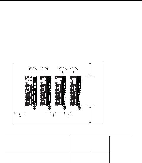
3.2 Installation Standards
The servo amplifier must be installed in a fully enclosed metal control panel. Observe the standards for mounting servo amplifiers in control panels, including those for the mounting servo amplifiers side by side in one control panel as shown in the following illustration.
•Servo Amplifier Mounting Orientation
Mount the servo amplifier vertically to the wall, with the front panel (the side with the panel operator display) facing out.
•Cooling
Refer to the following diagram and leave sufficient space for cooling by fans and natural convection.
•Mounting Servo Amplifiers Side by Side in a Control Panel
Fan |
Fan |
|
40 mm or more |
|
40 mm or more |
30 mm or more |
Width varies with |
|
|
|
servo amplifier model |
Leave sufficient space on each side and at the top and the bottom of each servo amplifier. The width on each side varies in accordance with the models of the servo amplifiers used.
Servo Amplifier Model SGDV- |
Side |
|
Top and bottom |
|
|
Left |
Right |
|
|
R70F, R90F, 2R1F, R70A, R90A, 1R6A, 2R8A |
1 mm or more |
|
|
|
|
|
|
||
2R8F, 3R8A, 5R5A, 7R6A |
1 mm or more |
10 mm or more |
|
|
40 mm or more
120A, 180A, 200A, 330A, 470A, 550A, 590A, 780A,
1R9D, 3R5D, 5R4D, 8R4D, 120D, 170D, 210D, 260D, 10 mm or more 280D, 370D
Also install cooling fans above the servo amplifiers to disperse local pockets of warmer air around the servo amplifiers.
•Inside the Control Panel
The conditions inside the control panel should be the same as the environmental conditions of the servo amplifier. Refer to the environmental. conditions in 2.1 General Specifications
•During Operation
Do not touch the connectors or IO cables during operation if the panel door is open.
.
10
3.3 Dimensions
3.3.1 MP2600iec Controller
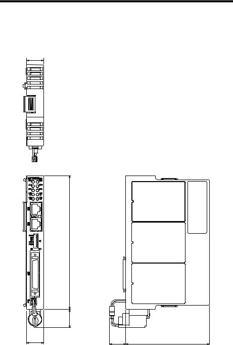
3.3 Dimensions
3.3.1MP2600iec Controller
20
160
( 22 ) |
20 |
Dimensions in mm.
(20) |
97 |
11

3.3 Dimensions
3.3.1 MP2600iec Controller
This page left intentionally blank
12

4.1 CN13 Connection Diagram
4 Inputs/Outputs
4.1 CN13 Connection Diagram
|
CN13 |
|
|
|
|
+15 |
|
|
|
|
V |
|
|
|
Analog |
|
-15V |
AO |
|
Output |
- |
1 |
||
|
+ |
26 |
AO_GND |
|
|
+15 |
|
|
|
|
V |
|
|
|
Analog |
-15V |
2 |
AI |
|
|
27 |
AI_GND |
||
Input |
- |
|
|
|
|
+ |
|
|
|
|
|
4 |
PA+ |
|
|
Encoder |
5 |
PA- |
|
|
29 |
PB+ |
||
|
Interface |
|||
|
|
30 |
PB- |
|
|
|
6 |
GND |
|
|
|
31 |
GND |
|
|
|
10 |
PILC(24V) |
|
|
|
34 |
PILC(12V) |
|
Z-phase |
|
9 |
PILC(5V) |
|
|
35 |
PIL |
||
Latch Input |
||||
|
|
|||
|
+5V |
|
|
|
|
|
13 |
DICOM |
|
|
|
38 |
DICOM |
|
Digital |
|
14 |
DI_00 |
|
|
39 |
DI_01 |
||
Input |
|
15 |
DI_02 |
|
|
|
40 |
DI_03 |
|
|
|
16 |
DI_04 |
|
|
|
41 |
DI_05 |
|
|
|
17 |
DI_06 |
|
|
|
42 |
DI_07 |
|
|
|
21 |
DO_00+ |
|
|
|
11 DO_00- |
||
|
|
46 |
DO_01+ |
|
|
|
36 |
DO_01- |
|
|
|
22 |
DO_02+ |
|
|
Digital |
12 |
DO_02- |
|
|
Output |
47 |
DO_03+ |
|
|
|
37 |
DO_03- |
|
|
|
23 |
DO_04+ |
|
|
Polyswitch Device: |
18 |
DO_04- |
|
|
48 |
DO_05+ |
||
|
A self-resetting |
|
|
|
|
fuse if excessive |
43 |
DO_05- |
|
|
current is drawn |
|||
|
24 |
DO_06+ |
||
|
from the output |
|||
|
|
|
||
|
|
19 |
DO_06- |
|
|
|
49 |
* DO_07+ |
|
|
|
44 |
* DO_07- |
|
|
FG Connector Shell) |
|
||
|
|
7 |
+ Battery |
|
|
|
32 |
- Battery |
|
External Device
|
|
|
|
|
|
|
L |
|
|
|
|
|
|
|
|
|
|
|
|
-10 |
+10V |
|||
FG |
|
|
|
|
External Device |
||||
|
|
|
||
|
|
|
|
|
|
|
V |
||
|
|
|
|
|
-10 |
+10V |
|||
FG |
|
|
|
|
Pulse
Generator
FG

 Connect a positive voltage to pin 10, 34, or 9 based on signal level
Latch Input
InputExternalSignal
L +24VDC
|
|
|
0V |
|
|
|
|
|
|
|
|
|
+24VDC |
|
|
|
L |
|
|
|
|
|
0V |
L Load |
|
|
|
||
|
|
|
||
|
|
L |
+24VDC |
|
|
|
|||
|
|
|
0V |
External Fuse |
|
|
|
||
|
|
|
(installed by |
|
|
|
|
||
|
|
L |
+24VDC |
customer) |
|
|
|||
|
|
|||
|
|
|
|
|
 0V
0V
L +24VDC
 0V
0V
L +24VDC
 0V
0V
L +24VDC
 0V
0V
L +24VDC
 0V
0V
NOTE: For a more detailed circuit drawing, see section 4.4.2.
* DO_07 can also be used as a high speed output when configured via parameter 1050
13
Loading...