


 Loading...
MotionSuite MP940 Machine Controller
Hardware Manual
Table of Contents |
|
Section 1: Introduction..................................................................................... |
1 |
Machine Controller ...................................................................................... |
1 |
Part Numbers ............................................................................................... |
3 |
Section 2: Startup.............................................................................................. |
5 |
Mounting Orientation .................................................................................. |
5 |
Mounting the MP940 to an SGDH .............................................................. |
6 |
Mounting the Battery Holder....................................................................... |
8 |
Power / Connections .................................................................................. |
11 |
Wiring - Single Phase .......................................................................... |
12 |
Wiring - Three Phase ........................................................................... |
13 |
SGDH and MP940 Startup Procedure ....................................................... |
14 |
Section 3: DIP Switch Definition ................................................................... |
15 |
Section 4: LED Indicators............................................................................... |
19 |
LED Display .............................................................................................. |
19 |
Section 5: Communications ............................................................................ |
21 |
Serial Communication ............................................................................... |
21 |
System Configuration .......................................................................... |
22 |
Communication Specifications ............................................................ |
23 |
Mechatrolink.............................................................................................. |
27 |
MP940 Master...................................................................................... |
27 |
Mechatrolink Connection .................................................................... |
28 |
DeviceNet .................................................................................................. |
29 |
Network Connections .......................................................................... |
29 |
Setting the Network Address ............................................................... |
30 |
Setting the Baud Rate .......................................................................... |
30 |
DeviceNet Status LEDs ....................................................................... |
31 |
Setup Requirements on the Network Master ....................................... |
31 |
Troubleshooting .................................................................................. |
32 |
i
Section 6: Digital I/O...................................................................................... |
39 |
Digital I/O Specifications .......................................................................... |
40 |
Section 7: Limit Switch Inputs ....................................................................... |
43 |
Section 8: Analog I/O ..................................................................................... |
45 |
Analog Input .............................................................................................. |
45 |
Analog Output............................................................................................ |
46 |
Section 9: External Encoder ........................................................................... |
47 |
External Encoder Specifications................................................................ |
48 |
Section 10: Registration Latch........................................................................ |
49 |
Main Encoder Registration Input............................................................... |
50 |
External Encoder Registration Input.......................................................... |
51 |
Section 11: Maintenance................................................................................. |
53 |
Battery Life ................................................................................................ |
53 |
Battery Replacement.................................................................................. |
53 |
Section 12: Specifications............................................................................... |
55 |
Physical Specifications .............................................................................. |
55 |
Hardware Specifications ............................................................................ |
56 |
Section 13: Dimensional Drawings and Cable Diagrams............................... |
59 |
Dimensions ................................................................................................ |
59 |
Connections ............................................................................................... |
63 |
Connector Specifications ........................................................................... |
64 |
I/O Connector ............................................................................................ |
65 |
Mechatrolink Cables .................................................................................. |
67 |
Mechatrolink Cable.............................................................................. |
67 |
ii
MotionSuite™ MP940 Machine Controller Hardware Manual |
Section 1: Introduction |
|
|
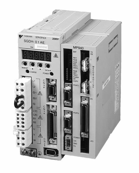
Section 1: Introduction
The MP940 is a 1.5 axis machine controller which connects to an SGDH servo amplifier via dual-port RAM.
This combination makes a fully integrated one-and-a-half-axis machine controller. It can be used to perform point-to-point positioning, or following of external devices. It has on-board digital and analog I/O, and network connections to link to other factory automation equipment.
Note: Refer to the SGDH User’s Manual for SGDH information.
Machine Controller
Figure 1.1: MP940 Machine Controller / SGDH Combination
1
MotionSuite™ MP940 Machine Controller Hardware Manual |
Section 1: Introduction |
|
|
|
|
SGDH |
MP940 |
|
|
|
|
|
ControlCurrent |
ControlSpeed |
|
MP940 |
|
Local |
DI |
|
PortDual |
|
DO |
||||
|
CPU |
|
I/O |
||||
M |
|
|
Motion |
|
|||
|
|
Profiler |
|
|
|
AO |
|
|
|
|
|
|
|
|
|
|
Counter |
RAM |
|
|
|
|
|
PG |
|
|
|
External |
|||
|
|
|
|
SERIAL |
Network |
||
AI |
|
A/D |
|
Encoder |
|||
|
|
|
|
|
|
||
|
|
|
RS-232C |
|
|
|
|
|
|
|
Motion |
|
|
|
|
|
|
|
Works+ |
RS-422/485 |
Network |
Network |
|
|
|
|
|
||||
|
|
|
|
|
Device 1 |
Device 2 |
|
|
|
|
Programming |
|
|
|
|
|
|
|
Device |
|
|
|
|
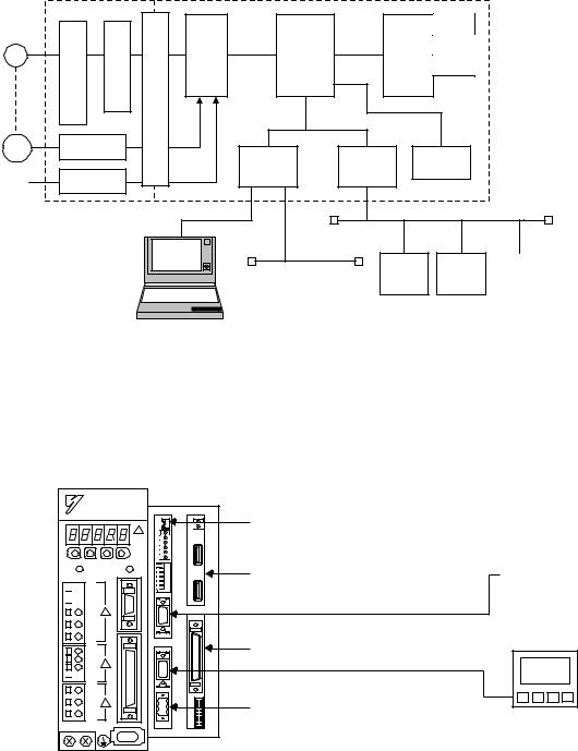
Figure 1.2: Block Diagram of MP940 Functions
SGDH Amplifier


 L1
L1


 L2
L2
L1C
L2C
B1


 B2
B2
a) MP940 |
Personal Computer |
|
|
MP940 |
|
|
e) Battery Connector |
|
|
|
X |
|
|
|
|
|
T |
|
|
|
|
BAT |
RX |
|
|
|
|
RDY |
|
|
. |
|
|
RUN |
|
|
|
|
|
ALM |
1 |
|
|
|
|
BAT |
|
||
|
|
PRT1 |
|
M |
|
|
|
PRT2 |
|
|
|
|
|
|
|
E |
|
|
435 6 |
RUN |
|
C |
c) Mechatrolink or DeviceNet Interface |
|
2 |
R |
|||
|
FLASH |
||||
|
|
INIT |
|
H |
|
|
|
|
A |
|
|
|
|
TEST |
|
T |
|
|
2 |
PP |
|
O |
|
|
1 |
COPY |
|
L |
|
NO |
|
|
I |
|
|
¨ |
|
|
|
N |
|
|
|
PORT1 |
|
K |
d) Port #1 Serial Cable |
|
|
|
|
|
|
|
|
|
I/O |
|
|
|
|
PORT2 |
|
|
b) I/O Connector |
|
|
|
|
|
d) Port #2 Serial Cable |
|
|
POWER |
|
|
|
|
|
+24V |
LED |
e) Power Connector |
|
|
|
FG |
|
|
|
|
|
GND |
|
|
|
|
|
|
|
|
Operator |
|
|
|
|
|
Interface |
2

MotionSuite™ MP940 Machine Controller Hardware Manual Section 1: Introduction
Part Numbers
|
|
|
|
Description |
Item Number |
|
|
|
|
|
|
||
MP940 |
a) |
Machine Controller with Mechatrolink Interface |
JEPMC-MC400 |
|||
|
|
|
||||
Machine Controller with DeviceNet Interface |
JEPMC-MC410 |
|||||
|
||||||
|
|
|
|
|
|
|
|
|
|
1.0m |
50 Pin I/O Cable |
JZSP-CKI01-1 |
|
|
|
|
|
|
|
|
I/O |
Cables |
b) |
2.0m |
50 Pin I/O Cable |
JZSP-CKI01-2 |
|
3.0m |
50 Pin I/O Cable |
JZSP-CKI01-3 |
||||
|
|
|
|
|
||
|
|
|
|
|
|
|
|
|
|
1.0m |
50 Pin I/O Cable (with terminal block) |
JUSP-TA50P |
|
|
|
|
|
|
||
|
|
|
Mechatrolink Cable 0.3m USB-USB |
JEPMC-W6000-A3 |
||
|
|
|
|
|
||
|
|
|
Mechatrolink Cable 0.5m USB-USB |
JEPMC-W6000-A5 |
||
Mechatrolink |
|
|
|
|
||
Cables |
|
Mechatrolink Cable 1.0m USB-USB |
JEPMC-W6000-01 |
|||
|
|
|
|
|||
c) |
Mechatrolink Cable 3.0m USB-USB |
JEPMC-W6000-03 |
||||
|
|
|||||
|
|
|
|
|
||
|
|
|
Mechatrolink Cable 5.0m USB-USB |
JEPMC-W6000-05 |
||
|
|
|
|
|
||
|
|
|
Mechatrolink Cable 10.0m USB-USB |
JPEMC-W6000-10 |
||
|
|
|
|
|
||
|
|
|
Mechatrolink Network Terminator Plug |
JEPMC-W6020 |
||
|
|
|
|
|
|
|
Serial |
Cables |
d) |
3.0m |
Port #1 Cable |
YS-15 |
|
3.0m |
Port #1 or Port #2 Pigtail Cable |
YS-14 |
||||
|
|
|
|
|
||
|
|
|
|
|
||
|
|
|
3.6V Lithium Battery (with cable and connector) |
BA000518 |
||
|
|
|
|
|
||
Accessories |
|
Battery Holder (replacement) |
DF9402712 |
|||
e) |
|
|
||||
Mounting Clip A (replacement) |
DF9402713 |
|||||
|
|
DC Power Supply Connector (replacement) |
UFS-0118 |
|||
|
|
|
|
|
||
|
|
|
Mounting Clip B (replacement) |
DF9402714 |
||
|
|
|
|
|
||
Software |
|
f) |
MotionWorks™ |
MPE720 |
||
|
|
|
|
|
||
|
|
MotionWorks+™ |
CP717PLUS |
|||
|
|
|
||||
|
|
|
|
|
|
|
3
MotionSuite™ MP940 Machine Controller Hardware Manual |
Section 1: Introduction |
|
|
NOTES:
4

MotionSuite™ MP940 Machine Controller Hardware Manual |
Section 2: Startup |
|
|
Section 2: Startup
Mounting Orientation
Mount the SGDH and MP940 in the appropriate direction for proper cooling, as shown on the left below.
Correct |
Incorrect |
SGDH MP940
SGDH MP940
Figure 2.1: Mounting Orientation
5
MotionSuite™ MP940 Machine Controller Hardware Manual |
Section 2: Startup |
|
|
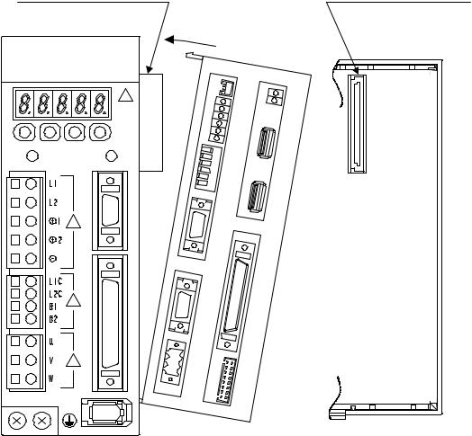
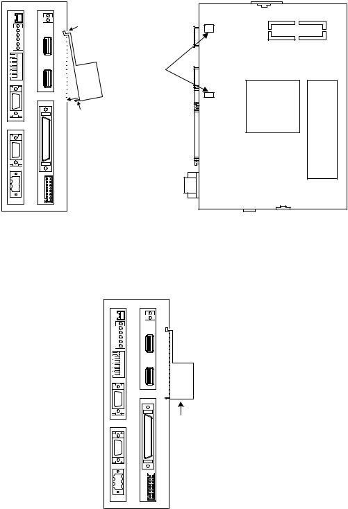
Mounting the MP940 to an SGDH
1.Insert the lower two mounting notches into the mounting holes at the bottom of the right side of the SGDH.
Servo Amplifier Connector |
Connector (connected to servo amplifier) |
|
2.
 YASKAWA SERVOPACK
SGDH-
MP940
6
5
4
3
2
1 ¨ NO
1.
Figure 2.2: Mounting the MP940 to an SGDH Servo Amplifier
2.Push the MP940 in the direction indicated by the arrows in the figure above, and insert the upper mounting notches of the MP940 into the upper mounting holes on the right side of the SGDH.
6
MotionSuite™ MP940 Machine Controller Hardware Manual |
Section 2: Startup |
|
|
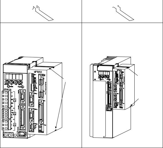
There are two types of mounting clips due to different sizes of servo amplifiers. See the following table before mounting.
Clip A × 2 |
Clip B × 1 |
SGDH-A3 |
SGDH-05 |
SGDH-20 |
SGDH-60 |
SGDH-A5 |
SGDH-08 |
SGDH-30 |
SGDH-75 |
SGDH-01 |
SGDH-10 |
SGDH-50 |
|
SGDH-02 |
SGDH-15 |
|
|
SGDH-04 |
|
|
|
 YASKAWA SERVOPACK SGDH-
200V
YASKAWA SERVOPACK |
200V |
SGDH- |
|
Clip A
Clip A
Clip B
|
|
|
|
|
|
|
|
|
|
|
|
|
|
|
|
|
|
|
|
|
|
|
|
|
|
|
|
|
|
|
|
|
|
|
|
|
|
|
|
|
|
|
|
|
|
|
|
|
|
|
|
|
|
|
|
|
|
|
|
|
|
|
|
|
|
|
|
|
|
|
|
|
|
|
|
|
Top/Bottom: Clip A |
Top: Clip A |
|
|
|
|
|
|
|
Bottom: Clip B |
|
7
MotionSuite™ MP940 Machine Controller Hardware Manual |
Section 2: Startup |
|
|
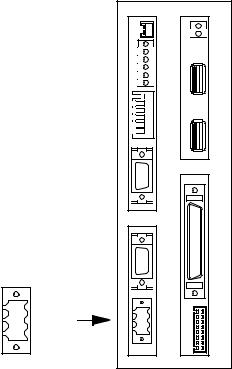
3.Insert the mounting clips into the mounting holes in the MP940, as shown in the figure below.
Servo Amplifier |
Mounting Hole |
3. |
|
Clip |
|
Clip Mounting |
MP940 |
Hook |
|
4.
Figure 2.3: Inserting the Mounting Clips
4.While pulling out on the mounting clip, hook the mounting clip on the top of the MP940 case.
5.Mount the lower clip in the same manner.
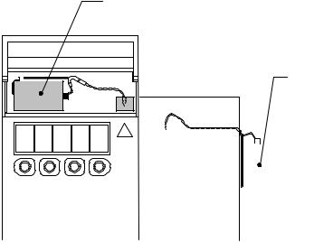
Mounting the Battery Holder
Follow the steps below to mount the battery holder. The mounting method for the MP940 battery holder is shown in the following figure.
1.Insert the battery holder into the MP940 upper battery holder mounting hole.
2.With the upper lock in contact with the battery holder mounting hole (top), push the bottom of the battery holder into the bottom mounting hole.
8
MotionSuite™ MP940 Machine Controller Hardware Manual |
Section 2: Startup |
|
|
|
|
MP940 |
|
|
BAT |
|
|
RDY |
|
|
RUN |
|
|
ALM |
|
|
BAT |
|
|
PRT1 |
|
|
PRT2 |
|
6 |
RUN |
|
5 |
INIT |
|
4 |
TEST |
|
3 |
FLASH |
|
2 |
PP |
|
1 |
COPY |
→ |
NO |
|
|
|
PORT1 |
PORT2
POWER
+24V
GND
FG
TX
RX
Upper lock
1 |
|
M |
|
E |
|
C |
|
H |
|
A |
|
T |
Battery Holder |
2 O |
|
R |
Mounting Holes |
N |
|
L |
|
I |
|
K |
|
|
|
I/O |
|
|
Push in this |
|
lock |
LED
Figure 2.4: Mounting the Battery Holder
3. Push the holder up to ensure it is securely mounted.
|
|
MP940 |
|
|
|
|
BAT |
TX |
|
|
|
RX |
|
|
|
|
|
|
|
|
|
RDY |
|
|
|
|
RUN |
|
|
|
|
ALM |
1 |
|
|
|
BAT |
|
|
|
|
|
|
|
|
|
PRT1 |
|
|
|
|
PRT2 |
|
M |
|
|
|
|
E |
|
6 |
RUN |
|
C |
|
|
H |
||
|
5 |
INIT |
|
|
|
|
A |
||
|
4 |
TEST |
|
T |
|
3 |
FLASH |
2 |
R |
|
2 |
PP |
O |
|
|
|
|
L |
|
|
1 |
COPY |
|
|
NO |
|
|
I |
|
¨ |
|
|
|
N |
|
|
PORT1 |
|
K |
|
|
|
|
|
|
|
|
I/O |
|
|
|
PORT2 |
|
|
POWER
+24V |
|
|
LED |
GND
FG
Figure 2.5: The Battery Holder is Securely Mounted
9
MotionSuite™ MP940 Machine Controller Hardware Manual |
Section 2: Startup |
|
|
Battery
A battery is needed during absolute encoder use for both MP940 and SGDH position data memory.
Battery for absolute encoder position data memory
Battery for RAM data backup and position data memory
SGDH Servo |
|
|
|
|
|
|
|
|
|
|
|
|
|
|
|
|
|
|
|
|
|
|
|
|
|
|
|
|
|
|
|
|
|
|
|
|
|
|
|
|
|
|
|
|
|
|
|
|
|
|
|
|
|
MP940 Module |
|
|
|
|
|
|||
Amplifier |
|
|
|
|
||||
|
|
|
|
|
|
|
|
|
Figure 2.6: MP940 and SGDH Batteries
The batteries are required under the conditions listed below:
SGDH |
MP940 |
|
Usage Method |
|
|
|
|
No |
No |
• FLASH Operation |
|
|
|
• |
Incremental encoder, or absolute encoder used as an |
|
|
|
incremental encoder. |
|
|
|
|
No |
Yes |
• No FLASH Operation (RAM used) |
|
|
|
• |
Incremental encoder, or absolute encoder used as an |
|
|
|
incremental encoder. |
|
|
|
|
Yes |
No |
• FLASH Operation |
|
|
|
• |
Absolute encoder used. |
|
|
|
|
Yes |
Yes |
• No FLASH Operation (RAM used) |
|
|
|
• |
Absolute encoder used. |
|
|
|
|
10
MotionSuite™ MP940 Machine Controller Hardware Manual |
Section 2: Startup |
|
|
Power / Connections
The MP940 must be supplied with 24VDC. Detailed information on power requirements for the SGDH are found in the SGDH User’s Manual.
Power Consumption |
20W |
|
|
Recommended Fuse Size |
1A |
|
|
Type of Power Supply |
Regulated 24VDC ±10% |
|
|
|
|
MP940 |
|
|
|
|
BAT |
|
TX |
|
|
|
RX |
|
|
|
|
|
|
|
|
RDY |
|
|
|
|
RUN |
|
|
|
|
ALM |
1 |
|
|
|
BAT |
|
|
|
|
|
|
|
|
|
PRT1 |
|
M |
|
|
PRT2 |
|
|
|
|
|
E |
|
|
|
|
|
|
|
6 |
RUN |
|
C |
|
|
H |
||
|
5 |
INIT |
|
|
|
|
A |
||
|
4 |
TEST |
|
T |
|
3 |
FLASH |
2 |
R |
|
2 |
PP |
O |
|
|
|
|
L |
|
|
1 |
COPY |
|
|
NO |
|
|
I |
|
¨ |
|
|
|
N |
|
|
PORT1 |
|
K |
|
|
|
|
|
|
|
|
I/O |
|
|
|
PORT2 |
|
|
POWER |
|
|
|
+24V |
POWER |
|
|
+24V |
LED |
||
|
|||
GND |
GND |
|
|
FG |
FG |
|
|
|
|
Figure 2.7: MP940 Power Connection
Signal |
Name |
|
|
+24V |
+24VDC Input |
|
|
GND |
0VDC Input |
|
|
FG |
Frame Ground |
|
|
11
MotionSuite™ MP940 Machine Controller Hardware Manual |
Section 2: Startup |
|
|
Wiring - Single Phase
Apply power to the SGDH and MP940 at the same time. If the SGDH is not powered within 10 seconds after turning power ON to the MP940 (or vice versa), the units will not communicate with each other. Note: For maximum noise immunity, connect the FG to a ground terminal on the sub-panel, or to the ground terminal on the SGDH.
R T 1MCCB
|
|
Control |
Control |
|
Noise Filter |
Power |
Power |
|
|||
|
|
ON |
OFF |
|
|
1MC
1MC |
Servo |
|
|
SUP |
Servo |
Emergency |
|
|
|
Power |
Power |
|
|
|
ON |
OFF |
Stop |
1MC |
2MC |
|
||||
2MC |
|
|
|
SUP |
|
|
|
MP940 |
|
|
|
|
|
BAT |
TX |
|
|
|
|
R |
|
|
|
|
|
|
X |
|
|
|
|
RDY |
|
|
|
|
|
RUN |
|
|
|
|
|
ALM |
1 |
|
|
|
|
BAT |
|
|
|
|
|
|
|
|
|
|
|
PRT1 |
|
M |
|
|
|
PRT2 |
|
|
|
|
|
|
E |
|
|
|
|
|
|
|
|
|
6 |
RUN |
|
C |
|
|
|
H |
||
|
|
5 |
INIT |
|
|
2MC |
|
2 |
A |
||
|
32 4 |
TEST |
O |
||
|
|
|
|
T |
|
|
|
|
FLASH |
|
R |
L1 |
|
|
PP |
|
L |
|
1 |
COPY |
|
||
|
NO |
|
I |
||
L2 |
|
|
|
|
N |
|
|
PORT1 |
|
K |
|
|
|
|
|
||
|
|
|
|
I/O |
|
1MC
L1C |
PORT2 |
L2C |
|
B1 |
|
B2 |
|
|
|
|
|
|
|
|
|
|
|
|
|
POWER |
|
|
|
|
|
|
|
|
|
|
|
|
|
|
|
|
|
|
|
|
|
|
|
||
|
|
|
|
|
|
|
|
|
|
|
|
+24V |
|
|
|
LED |
||
|
|
|
|
|
|
|
|
|
|
|
|
GND |
|
|
|
|
||
|
|
|
|
|
|
|
|
|
|
|
|
FG |
|
|
|
|||
|
|
|
|
|
|
|
|
|
|
|
|
|
|
|
|
|
|
|
|
|
|
|
|
|
|
|
|
|
|
|
|
|
|
|
|
|
|
|
|
|
|
|
|
|
|
|
|
|
|
|
|
|
|
|
|
|
|
|
|
|
|
|
|
|
|
|
|
|
|
|
|
|
|
|
|
|
|
|
|
|
|
|
|
|
|
|
|
|
|
|
|
|
|
|
|
|
|
|
|
|
|
|
|
|
|
|
|
|
|
|
|
|
|
|
|
|
|
|
|
|
|
|
|
|
|
|
|
|
|
|
|
|
|
|
+24V |
+24V |
|
24VDC |
||
|
|
||
|
Supply |
|
0V |
|
|
|
|
|
|
|
|
Figure 2.8: Single-phase Wiring
12
MotionSuite™ MP940 Machine Controller Hardware Manual |
Section 2: Startup |
|
|
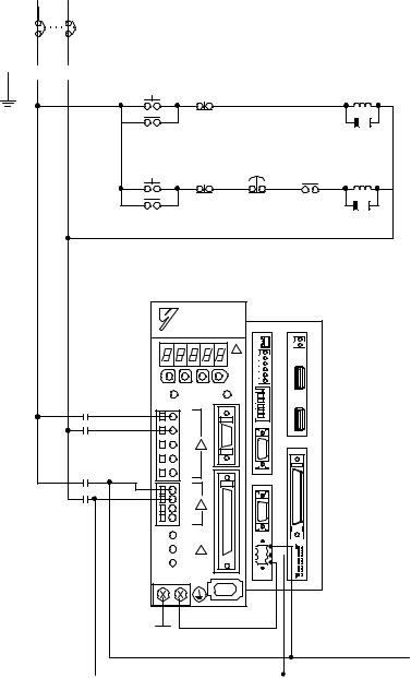
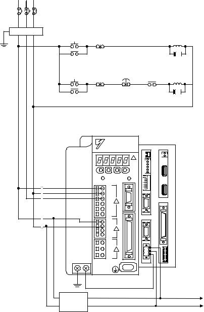
Wiring - Three Phase
Apply power to the SGDH and MP940 simultaneously. If the SGDH is not powered within 10 seconds after turning power ON to the MP940 (or vice versa), the units will not communicate with each other. Note: For maximum noise immunity, connect the FG to a ground terminal on the sub-panel, or to the ground terminal on the SGDH.
R S T 1MCCB
Noise Filter |
Control |
Control |
|
|
|
|
|
Power |
Power |
|
|
|
|
|
|
|
|
|
|
|
|
||
|
ON |
OFF |
|
|
|
|
1MC |
|
1MC |
|
|
|
|
|
SUP |
|
Servo |
Servo |
Emergency |
|
|
|
|
|
Power |
Power |
|
|
|
|
|
|
Stop |
|
|
|
|
||
|
ON |
OFF |
1MC |
|
2MC |
||
|
|
|
|||||
|
2MC |
|
|
|
|
|
SUP |
|
|
|
|
|
MP940 |
|
|
|
|
|
|
|
BAT |
TX |
|
|
|
|
|
|
R |
||
|
|
|
|
|
|
X |
|
|
|
|
|
|
RDY |
|
|
|
|
|
|
|
RUN |
|
|
|
|
|
|
|
ALM |
1 |
|
|
|
|
|
|
BAT |
|
|
|
|
|
|
|
|
|
|
|
|
|
|
|
PRT1 |
|
M |
|
|
|
|
|
PRT2 |
|
|
|
|
|
|
|
|
|
E |
|
|
|
|
6 |
RUN |
|
C |
|
|
|
|
|
H |
||
|
|
|
|
5 |
INIT |
|
|
|
2MC |
|
|
|
A |
||
|
|
|
23 4 |
TEST |
2 |
T |
|
|
|
|
PP |
O |
|||
|
|
L1 |
|
|
FLASH |
|
R |
|
|
|
NO |
|
|
I |
|
|
|
|
|
1 |
COPY |
|
L |
|
|
|
|
|
|
||
|
|
L2 |
|
|
|
|
N |
|
|
|
|
PORT1 |
|
K |
|
|
|
L3 |
|
|
|
|
|
|
|
|
|
|
|
|
I/O |
|
1MC |
|
|
|
|
|
|
|
|
L1C |
|
|
PORT2 |
|
|
|
|
L2C |
|
|
|
|
|
|
|
B1 |
|
|
|
|
|
|
|
B2 |
|
|
|
|
|
|
|
|
|
|
POWER |
|
|
|
|
|
|
|
+24V |
|
LED |
|
|
|
|
|
GND |
|
|
|
|
|
|
|
FG |
|
|
|
24VDC |
+24V |
|
|
|
|
+24V |
|
|
|
|
|
|
||
|
Supply |
|
|
|
|
|
0V |
Figure 2.9: Three-phase Wiring
13
MotionSuite™ MP940 Machine Controller Hardware Manual |
Section 2: Startup |
|
|
SGDH and MP940 Startup Procedure
Follow the steps below to set up the system.
1.Set the DIP switch of the MP940 as “MEMORY CLEAR”. (Only ‘INIT’ and TEST are ON.)
2.Apply power to both the SGDH and the MP940.
3.Verify that the MP940 is initialized. (RDY and RUN LED lights blink.)
4.Set the DIP switch to normal operation. (Only RUN is ON).
5.Cycle the power of the MP940 and the SGDH.
6.Start the MotionSuite™ software tool and connect ON LINE.
14

MotionSuite™ MP940 Machine Controller Hardware Manual |
Section 3: DIP Switch Definition |
|
|
Section 3: DIP Switch Definition
The function of the six switches is explained in the table below.
←
1 2 3 4 5 6
NO
RUN
INITIAL TEST
FLASH P.P
COPY
Figure 3.1: MP940 DIP Switches
DIP Switch Settings
Number |
Name |
Setting |
Function |
Default |
|
Setting |
|||||
|
|
|
|
||
|
|
|
|
|
|
6 |
RUN |
ON |
Application program runs at power ON |
ON |
|
|
|
|
|
|
|
|
|
OFF |
Application program does not run at power ON |
|
|
|
|
|
|
|
|
5 |
INIT |
ON |
When DIP switch 4 is OFF: |
OFF |
|
|
|
|
Data is copied from flash memory to RAM at power ON. |
|
|
|
|
|
When DIP switch 4 is ON: |
|
|
|
|
|
Memory is cleared. |
|
|
|
|
|
|
|
|
|
|
OFF |
When DIP switch 4 is OFF: |
|
|
|
|
|
Data is not copied from flash memory to RAM at power ON. |
|
|
|
|
|
When DIP switch 4 is ON: |
|
|
|
|
|
Nothing |
|
|
|
|
|
|
|
|
4 |
TEST |
ON |
Terminal Mode/Initialization Mode |
OFF |
|
|
|
|
|
|
|
|
|
OFF |
Online |
|
|
|
|
|
|
|
|
3 |
FLASH |
ON |
Program is copied from flash memory to RAM at power ON. |
OFF |
|
|
|
|
|
|
|
|
|
OFF |
Program is not copied from flash memory to RAM at power ON |
|
|
|
|
|
|
|
|
2 |
Programming |
ON |
Defaults to Port 1 only |
OFF |
|
|
Port Default |
|
|
|
|
|
OFF |
The programming port is set up through software selection |
|
||
|
|
|
|||
|
|
|
|
|
|
1 |
COPY |
ON |
Global variables are copied from flash at power ON |
OFF |
|
|
|
|
|
|
|
|
|
OFF |
Global variables are not copied from flash at power ON. |
|
|
|
|
|
|
|
15
MotionSuite™ MP940 Machine Controller Hardware Manual |
Section 3: DIP Switch Definition |
|
|
Memory Initialization
To erase the application program, variables, and configuration data, set the DIP switches in the following order.
Step 1 |
|
|
|
Step 2 |
Step 3 |
|
|
|
Step 4 |
Step 5 |
||
|
|
|
|
|
|
|
|
|
|
|
|
|
Turn the MP940 |
Turn the INIT and |
Turn on the power, |
Turn the power |
Turn power ON. |
||||||||
power OFF |
TEST DIP |
and check that the |
OFF. Turn the Run |
|
||||||||
|
switches to ON |
RDY and RUN |
DIP switch ON. |
|
||||||||
|
|
|
|
|
|
LEDs are flashing |
|
|
|
|
|
|
|
|
|
|
|
|
(approximately 3s). |
|
|
|
|
RUN |
|
|
|
|
|
|
RUN |
|
|
|
6 |
|
||
|
|
|
|
6 |
|
|
|
|
|
|||
|
|
|
|
|
|
|
|
|
||||
|
|
|
|
|
|
|
|
|
||||
|
|
|
|
|
|
|
|
|
|
|||
|
|
|
|
|
|
|
|
5 |
INITIAL |
|
||
|
|
|
|
5 |
INITIAL |
|
|
|
|
|
||
|
|
|
|
|
|
|
|
|
||||
|
|
|
|
|
|
|
|
|
||||
|
|
|
|
|
|
|
|
4 |
TEST |
|
||
|
|
|
|
|
|
|
|
|
||||
|
|
|
|
4 |
TEST |
|
|
|
|
|
||
|
|
|
|
|
|
|
|
|
||||
|
|
|
|
|
|
|
|
3 |
FLASH |
|
||
|
|
|
|
3 |
FLASH |
|
|
|
|
|
||
|
|
|
|
|
|
|
|
|
||||
|
|
|
|
|
|
|
|
2 |
P.P |
|
||
|
|
|
|
|
|
|
|
|
||||
|
|
|
|
2 |
P.P |
|
|
|
|
|
||
|
|
|
|
|
|
|
|
|
||||
|
|
|
|
|
|
|
|
1 |
COPY |
|
||
|
|
|
|
1 |
COPY |
|
|
|
|
|
||
|
|
|
|
|
|
|
|
|
||||
|
|
|
|
|
|
|
|
|
||||
|
|
|
|
|
|
← |
NO |
|
|
|||
|
|
← |
NO |
|
|
|
|
|
||||
|
|
|
|
|
|
|
|
|
|
|||
|
|
|
|
|
|
|
|
|
|
|
|
|
|
|
|
|
|
|
|
|
|
|
|
|
|
Note:Perform memory initialization if controller power is turned OFF while the battery is removed. This is not necessary if using the “Copy from Flash at Power Up” mode.
Standard Operation
The DIP switch pattern shown is the factory default setting.
←
1 2 3 4 5 6
NO
RUN
INITIAL TEST
FLASH P.P
COPY
Figure 3.2: Factory Default Setting
16

MotionSuite™ MP940 Machine Controller Hardware Manual |
Section 3: DIP Switch Definition |
|
|
Flash Memory Operation
Outline Of Flash Operation
Programs created by the user are normally stored in RAM. The CPU executes programs stored in RAM. The programs stored in RAM can also be saved to the flash memory. Running programs after copying them from flash to RAM at power ON is called flash operation.
Flash memory saves programs even if there is no memory backup battery.
Flash Start Mode
Transfer from flash memory to RAM occurs when DIP switch 3 is ON (flipped to the right) and the power is turned ON.
Note: MotionSuite™ software tools have a setting which copies the application program to flash when downloading. Refer to the software manual for details. The flash start mode does not work unless an application program has been saved to flash.
←
1 2 3 4 5 6
NO
RUN
INITIAL TEST
FLASH P.P
COPY
Figure 3.3: Transfer from Flash Memory to RAM
Retaining Variable Data
The lithium battery makes it possible to save variable data in RAM even when the power is OFF. This is useful when saving data that changes during operation, such as a parts counter, or specific information about a job run. Programming must be written so that specific variables that must be retained are not initialized every time the power is turned ON.
17
MotionSuite™ MP940 Machine Controller Hardware Manual |
Section 3: DIP Switch Definition |
|
|
Copying Servo Amplifier Pn Data from MP940 to SGDH
It is possible to load parameter data that was downloaded to the controller via MotionWorks or MotionWorks+ by turning off all DIP switches except the copy switch. The parameter transfer will occur at power up. The display panel on the SGDH will go off during the parameter transfer. Return the DIP switches to standard operation and cycle power after the operation is complete.
18
MotionSuite™ MP940 Machine Controller Hardware Manual |
Section 4: LED Indicators |
|
|
Section 4: LED Indicators
LED Display
The MP940 runs a series of tests during start-up. If an error is detected, the ERR LED flashes, and the content of the error corresponds to the number of flashes. MotionSuite™ software tools cannot communicate with the controller while an error LED is flashing or memory initialization is occurring. The MP940 LEDs are shown in the following table.
LED Display Patterns
|
|
LED |
|
|
|
|
Type |
|
|
|
|
|
Meaning |
RDY |
RUN |
ERR |
BAT |
|
||
|
|
|
||||
|
(Green) |
(Green) |
(Red) |
(Red) |
|
|
|
|
|
|
|
|
|
Normal |
ON |
OFF |
OFF |
OFF |
Application program stopped |
|
|
|
|
|
|
|
|
|
ON |
ON |
OFF |
OFF |
Normal application program execution |
|
|
|
|
|
|
|
|
Error |
OFF |
OFF |
ON |
OFF |
Memory error (initialization may be required) |
|
|
|
|
|
|
|
|
|
OFF |
OFF |
OFF |
OFF |
Initial operation (when display continues) |
|
|
|
|
|
|
|
|
|
|
|
|
|
1. |
2 flashes: RAM error |
|
OFF |
OFF |
Flashing |
OFF |
2. |
3 flashes: ROM error |
|
|
|
|
|
3. |
4 flashes: Peripheral LSI letter |
|
|
|
|
|
|
|
Warning |
— |
— |
— |
ON |
Battery alarm |
|
|
|
|
|
|
|
|
|
ON |
ON |
ON |
OFF |
1. |
Operand error or I/O error |
|
|
|
|
|
|
|
|
System (S) register message |
|
Hardware status (Momentary Stop, RUN/STOP, Test- |
|||
|
(no LED display) |
|
|
ing Mode, etc.) |
||
|
|
|
|
|
|
|
Other |
Flashing |
Flashing |
OFF |
OFF |
Memory initialization by DIP switch setting complete. |
|
|
|
|
|
|
|
|
|
OFF |
OFF |
ON |
OFF |
Offline testing mode. |
|
|
|
|
|
|
|
|
In addition, there are the following four LEDs.
Description |
Type |
Color |
Meaning |
|
|
|
|
PRT1 |
RS232 |
Green |
Flashes to indicate communication |
|
|
|
|
PRT2 |
RS422 |
Green |
Flashes to indicate communication |
|
|
|
|
TX |
Mechatrolink |
Green |
Flashes to indicate communication |
|
|
|
|
RX |
Mechatrolink |
Green |
Flashes to indicate communication |
|
|
|
|
19
Loading...