


 Loading...
Machine Controller MP3000 Series
MP3200/MP3300
TROUBLESHOOTING MANUAL
Overview of Troubleshooting
Troubleshooting with Indicators and Displays
Troubleshooting using the System Monitor
Troubleshooting Communications and Motion Control
Troubleshooting Programming
and Debugging
Troubleshooting Connections
with the MPE720
Troubleshooting System Errors
MP3200/MP3300 Battery Replacement
Fan Replacement
1
2
3
4
5
6
7
8
9
MANUAL NO. SIEP C880725 01B

Copyright © 2012 YASKAWA ELECTRIC CORPORATION
All rights reserved. No part of this publication may be reproduced, stored in a retrieval system, or transmitted, in any form, or by any means, mechanical, electronic, photocopying, recording, or otherwise, without the prior written permission of Yaskawa. No patent liability is assumed with respect to the use of the information contained herein. Moreover, because Yaskawa is constantly striving to improve its high-quality products, the information contained in this manual is subject to change without notice. Every precaution has been taken in the preparation of this manual. Nevertheless, Yaskawa assumes no responsibility for errors or omissions. Neither is any liability assumed for damages resulting from the use of the information contained in this publication.

About this Manual
This manual describes troubleshooting the MP3200 and MP3300.
For information on troubleshooting Optional Modules, refer to the manual for your Optional Modules.
Read this manual carefully to ensure the correct usage of the Machine Controller in the control of your manufacturing system.
Keep this manual in a safe place so that it can be referred to whenever necessary.
Using this Manual
Basic Terms
Unless otherwise specified, the following definitions are used:
•MP3200: A generic name for the Power Supply Unit, CPU Unit, Base Unit, and Rack Expansion Interface Unit.
•MP3300: A generic name for the CPU Module and Base Unit.
•MPE720: The Engineering Tool or a personal computer running the Engineering Tool
•PLC: A Programmable Logic Controller
•Machine Controller: An MP3000-series Machine Controller
•Motion Control Function Modules: The Function Modules in the Motion Modules and the Function Mod-
ules in the SVC, SVR, SVC 32, or SVR 32 built into the CPU Units/ CPU Modules.
Manual Configuration
This manual consists of the chapters listed in the following table. Read the chapters of this manual as required for your application.
|
Chapter Title |
Troubleshooting |
Chapter 1 |
Overview of Troubleshooting |
√ |
Chapter 2 |
Troubleshooting Errors with LED Indicators and Displays |
√ |
Chapter 3 |
Troubleshooting using the System Monitor |
√ |
Chapter 4 |
Troubleshooting Communications and Motion Control |
√ |
Chapter 5 |
Troubleshooting Programming and Debugging |
√ |
Chapter 6 |
Troubleshooting Connections with the MPE720 |
√ |
Chapter 7 |
Troubleshooting System Errors |
√ |
Chapter 8 |
MP3200/MP3300 Battery Replacement |
√ |
Chapter 9 |
Fan Replacement |
√ |
MPE720 Engineering Tool Version Number
In this manual, the operation of MPE720 is described using screen captures of MPE720 version 7.
iii

Copyrights
•DeviceNet is a registered trademark of the ODVA (Open DeviceNet Venders Association).
•Ethernet is a registered trademark of the Xerox Corporation.
•MPLINK is a registered trademark of Yaskawa Electric Corporation.
•Microsoft, Windows, Windows NT, and Internet Explorer are trademarks or registered trademarks of the Microsoft Corporation.
•PROFIBUS is a trademark of the PROFIBUS User Organization.
•MECHATROLINK is a trademark of the MECHATROLINK Members Association.
•Other product names and company names are the trademarks or registered trademarks of the respective company. “TM” and the → mark do not appear with product or company names in this manual.
Visual Aids
The following aids are used to indicate certain types of information for easier reference.
|
Indicates precautions or restrictions that must be observed. |
Important |
Indicates alarm displays and other precautions that will not result in machine damage. |
|
Indicates items for which caution is required or precautions to prevent operating mistakes.
Note
Example Indicates operating or setting examples.
Information Indicates supplemental information to deepen understanding or useful information.
Indicates definitions of difficult terms or terms that have not been previously explained in this
manual.
Terms
iv

Related Manuals
The following table lists the related manuals.
Be aware of all product specifications and restrictions to product application before you attempt to use any product.
Category |
Manual Name |
Manual Number |
Contents |
|
|
|
|
Describes the functions of the MP2000/ |
|
|
Machine Controller MP2000/MP3000 |
|
MP3000-series Machine Controllers and the |
|
|
|
procedures that are required to use the |
||
|
Series Machine Controller System |
SIEP C880725 00 |
||
|
Setup Manual |
|
Machine Controller, from installation and |
|
|
|
connections to settings, programming, trial |
||
|
|
|
||
|
|
|
operation, and debugging. |
|
|
|
|
|
|
|
Machine Controller MP3000 Series |
|
Describes the specifications and system con- |
|
|
|
figuration of an MP3000-series MP3200 |
||
Basic |
MP3200 |
SIEP C880725 10 |
||
User’s Manual |
|
Machine Controller and the functions of the |
||
functionality |
|
CPU Unit. |
||
|
|
|||
|
Machine Controller MP3000 Series |
|
Describes the specifications and system con- |
|
|
|
figuration of an MP3000-series MP3300 |
||
|
MP3300 |
SIEP C880725 21 |
||
|
Product Manual |
|
Machine Controller and the functions of the |
|
|
|
CPU Module. |
||
|
|
|
||
|
|
|
|
|
|
Machine Controller MP2000 Series |
|
Describes the functions, specifications, oper- |
|
|
|
ating methods, maintenance, inspections, and |
||
|
MPU-01 Multi-CPU Module |
SIEP C880781 05 |
||
|
troubleshooting of the MP2000-series MPU- |
|||
|
User’s Manual |
|
01 Multi-CPU Module. |
|
|
|
|
||
|
|
|
|
|
|
Machine Controller MP3000 Series |
|
Describes the specifications, system configu- |
|
Communica- |
|
ration, and communications connection |
||
tions |
Communications |
SIEP C880725 12 |
methods for the Ethernet communications |
|
functionality |
User's Manual |
|
that are used with an MP3000-series Machine |
|
|
|
|
Controller. |
|
|
|
|
Describes the specifications, system configu- |
|
|
Machine Controller MP3000 Series |
|
ration, and operating methods for the SVC, |
|
|
Motion Control |
SIEP C880725 11 |
SVC32, SVR, and SVR32 Motion Function |
|
|
User's Manual |
|
Modules that are used in an MP3000-series |
|
|
|
|
Machine Controller. |
|
|
Machine Controller MP2000 Series |
|
Describes the functions, specifications, and |
|
|
Built-in SVB/SVB-01 Motion Module |
SIEP C880700 33 |
operating methods of the MP2000-series PO- |
|
Motion |
User's Manual |
|
01 Motion Module. |
|
|
|
|
||
Machine Controller MP2000 Series |
|
Describes the functions, specifications, and |
||
control |
|
|||
SVC-01 Motion Module |
SIEP C880700 41 |
operating methods of the MP2000-series |
||
functionality |
||||
User's Manual |
|
SVA-01 Motion Module. |
||
|
|
|||
|
|
|
|
|
|
Machine Controller MP2000 Series |
|
Describes the functions, specifications, and |
|
|
SIEP C880700 32 |
operating methods of MP2000-series Motion |
||
|
SVA-01 Motion Module |
|||
|
Modules (built-in Function Modules: SVB, |
|||
|
User's Manual |
|
SVB-01, and SVR). |
|
|
|
|
||
|
|
|
|
|
|
Machine Controller MP2000 Series |
|
Describes the functions, specifications, and |
|
|
Pulse Output Motion Module PO-01 |
SIEP C880700 28 |
operating methods of the MP2000-series PO- |
|
|
User's Manual |
|
01 Motion Module. |
|
|
|
|
|
|
|
|
|
Continued on next page. |
v

|
|
|
Continued from previous page. |
|
|
|
|
|
|
Category |
Manual Name |
Manual Number |
Contents |
|
|
Machine Controller MP3000 Series |
|
Describes the ladder programming specifica- |
|
|
SIEP C880725 13 |
tions and instructions of MP3000-series |
||
|
Ladder Programming Manual |
|||
Program- |
|
Machine Controller. |
||
|
|
|||
|
|
|
||
|
|
Describes the motion programming and |
||
ming |
|
|
||
Machine Controller MP3000 Series |
|
sequence programming specifications and |
||
|
SIEP C880725 14 |
|||
|
Motion Programming Manual |
|
instructions of MP3000-series Machine Con- |
|
|
|
|
troller. |
|
|
|
|
|
|
|
MPE720 Version 7 System Integrated |
|
|
|
Engineering |
Engineering Tool for MP2000/MP3000 |
SIEP C880761 03 |
Describes how to operate MPE720 version 7. |
|
Tools |
Series Machine Controller |
|||
|
|
|||
|
User’s Manual |
|
|
|
|
|
|
|
vi
Safety Precautions
The following signal words and marks are used to indicate safety precautions in this manual.
Information marked as shown below is important for safety. Always read this information and heed the precautions that are provided.
 WARNING
 CAUTION
 PROHIBITED
 MANDATORY
Indicates precautions that, if not heeded, could possibly result in loss of life or serious injury.
Indicates precautions that, if not heeded, could result in relatively serious or minor injury, or property damage.
If not heeded, even precautions classified as cautions (  CAUTION ) can lead to serious results depending on circumstances.
Indicates prohibited actions. For example,  indicates prohibition of open flame.
Indicates mandatory actions. For example,  indicates that grounding is required.
The following precautions are for storage, transportation, installation, wiring, operation, maintenance, inspection, and disposal. These precautions are important and must be observed.
General Precautions
 WARNING
•The installation must be suitable and it must be performed only by an experienced technician.
There is a risk of electrical shock or injury.
•Before connecting the machine and starting operation, make sure that an emergency stop procedure has been provided and is working correctly.
There is a risk of injury.
•Do not approach the machine after a momentary interruption to the power supply. When power is restored, the Machine Controller and the device connected to it may start operation suddenly. Provide safety measures in advance to ensure human safety when operation restarts.
There is a risk of injury.
•Do not touch anything inside the Machine Controller.
There is a risk of electrical shock.
•Do not remove the front cover, cables, connector, or options while power is being supplied.
There is a risk of electrical shock, malfunction, or damage.
•Do not damage, pull on, apply excessive force to, place heavy objects on, or pinch the cables.
There is a risk of electrical shock, operational failure of the Machine Controller, or burning.
•Do not attempt to modify the Machine Controller in any way.
There is a risk of injury or device damage.
vii

Storage and Transportation
 CAUTION
•Do not store the Machine Controller in any of the following locations.
•Locations that are subject to direct sunlight
•Locations that are subject to ambient temperatures that exceed the storage conditions
•Locations that are subject to ambient humidity that exceeds the storage conditions
•Locations that are subject to rapid temperature changes and condensation
•Locations that are subject to corrosive or inflammable gas
•Locations that are subject to excessive dust, dirt, salt, or metallic powder
•Locations that are subject to water, oil, or chemicals
•Locations that are subject to vibration or shock
There is a risk of fire, electrical shock, or device damage.
•Hold onto the main body of the Machine Controller when transporting it.
Holding the cables or connectors may damage them or result in injury.
•Do not overload the Machine Controller during transportation. (Follow all instructions.)
There is a risk of injury or an accident.
•Never subject the Machine Controller to an atmosphere containing halogen (fluorine, chlorine, bromine, or iodine) during transportation.
There is a risk of malfunction or damage.
•If disinfectants or insecticides must be used to treat packing materials such as wooden frames, pallets, or plywood, the packing materials must be treated before the product is packaged, and methods other than fumigation must be used.
Example: Heat treatment, where materials are kiln-dried to a core temperature of 56°C for 30 minutes or more.
If the electronic products, which include stand-alone products and products installed in machines, are packed with fumigated wooden materials, the electrical components may be greatly damaged by the gases or fumes resulting from the fumigation process. In particular, disinfectants containing halogen, which includes chlorine, fluorine, bromine, or iodine can contribute to the erosion of the capacitors.
viii

Installation
 CAUTION
•Do not install the Machine Controller in any of the following locations.
•Locations that are subject to direct sunlight
•Locations that are subject to ambient temperatures that exceed the operating conditions
•Locations that are subject to ambient humidity that exceeds the operating conditions
•Locations that are subject to rapid temperature changes and condensation
•Locations that are subject to corrosive or inflammable gas
•Locations that are subject to excessive dust, dirt, salt, or metallic powder
•Locations that are subject to water, oil, or chemicals
•Locations that are subject to vibration or shock
There is a risk of fire, electrical shock, or device damage.
•Never install the Machine Controller in an atmosphere containing halogen (fluorine, chlorine, bromine, or iodine).
There is a risk of malfunction or damage.
•Do not step on the Machine Controller or place heavy objects on the Machine Controller.
There is a risk of injury or an accident.
•Do not block the air exhaust ports on the Machine Controller. Do not allow foreign objects to enter the Machine Controller.
There is a risk of internal element deterioration, malfunction, or fire.
•Always mount the Machine Controller in the specified orientation.
There is a risk of malfunction.
•Leave the specified amount of space between the Machine Controller, and the interior surface of the control panel and other devices.
There is a risk of fire or malfunction.
•Do not subject the Machine Controller to strong shock.
There is a risk of malfunction.
•Suitable battery installation must be performed and it must be performed only by an experienced technician.
There is a risk of electrical shock, injury, or device damage.
•Do not touch the electrodes of the Battery.
Static electricity may damage the electrodes.
ix

Wiring
 CAUTION
•Check the wiring to be sure it has been performed correctly.
There is a risk of motor run-away, injury, or accidents.
•Always use a power supply of the specified voltage.
There is a risk of fire or accident.
•In places with poor power supply conditions, ensure that the input power is supplied within the specified voltage range.
There is a risk of device damage.
•Install breakers and other safety measures to provide protection against shorts in external wiring.
There is a risk of fire.
•Provide sufficient shielding when using the Machine Controller in the following locations.
•Locations that are subject to noise, such as from static electricity
•Locations that are subject to strong electromagnetic or magnetic fields
•Locations that are subject to radiation
•Locations that are near power lines
There is a risk of device damage.
•Configure the circuits to turn ON the power supply to the CPU Unit/CPU Module before the 24- V I/O power supply. Refer to the following manual for details on circuits.

 MP3000 Series CPU Unit Instructions (Manual No.: TOBP C880725 16)

 MP3000 Series MP3300 CPU Module Instructions Manual (Manual No.: TOBP C880725 23)
If the power supply to the CPU Unit/CPU Module is turned ON after the external power supply, e.g., the 24-V I/O power supply, the outputs from the CPU Unit/CPU Module may momentarily turn ON when the power supply to the CPU Unit/CPU Module turns ON. This can result in unexpected operation that may cause injury or device damage.
•Provide emergency stop circuits, interlock circuits, limit circuits, and any other required safety measures in control circuits outside of the Machine Controller.
There is a risk of injury or device damage.
•If you use MECHATROLINK I/O Modules, use the establishment of MECHATROLINK communications as an interlock output condition.
There is a risk of device damage.
•Connect the Battery with the correct polarity.
There is a risk of battery damage or explosion.
•Suitable battery replacement must be performed and it must be performed only by an experienced technician.
There is a risk of electrical shock, injury, or device damage.
•Do not touch the electrodes when replacing the Battery.
Static electricity may damage the electrodes.
•Select the I/O signal wires for external wiring to connect the Machine Controller to external devices based on the following criteria:
•Mechanical strength
•Noise interference
•Wiring distance
•Signal voltage
x
 CAUTION
•Separate the I/O signal cables for control circuits from the power cables both inside and outside the control panel to reduce the influence of noise from the power cables.
If the I/O signal lines and power lines are not separated properly, malfunction may occur.
Example of Separated Cables
Steel separator
Power cable |
I/O signal |
cables in |
|
|
control circuits |
Operation
 CAUTION
•Follow the procedures and instructions in the user’s manuals for the relevant products to perform normal operation and trial operation.
Operating mistakes while the Servomotor and machine are connected may damage the machine or even cause accidents resulting in injury or death.
•Implement interlock signals and other safety circuits external to the Machine Controller to ensure safety in the overall system even if the following conditions occur.
•Machine Controller failure or errors caused by external factors
•Shutdown of operation due to Machine Controller detection of an error in self-diagnosis and the subsequent turning OFF or holding of output signals
•Holding of the ON or OFF status of outputs from the Machine Controller due to fusing or burning of output relays or damage to output transistors
•Voltage drops from overloads or short-circuits in the 24-V output from the Machine Controller and the subsequent inability to output signals
•Unexpected outputs due to errors in the power supply, I/O, or memory that cannot be detected by the Machine Controller through self-diagnosis.
There is a risk of injury, device damage, or burning.
•Observe the setting methods that are given in the manual for the following parameters.
•Parameters for absolute position detection when the axis type is set to a finite-length axis
•Parameters for simple absolute infinite-length position control when the axis type is set to an infinitelength axis

 MP3000 Series Motion Control User’s Manual (Manual No. SIEP C880725 11)
If any other methods are used, offset in the current position when the power supply is turned OFF and ON again may result in device damage.
•OL48 (Zero Point Position Offset in Machine Coordinate System) is always valid when the axis type is set to a finite-length axis. Do not change the setting of OL48 while the Machine Controller is operating.
There is a risk of machine damage or an accident.
xi
 CAUTION
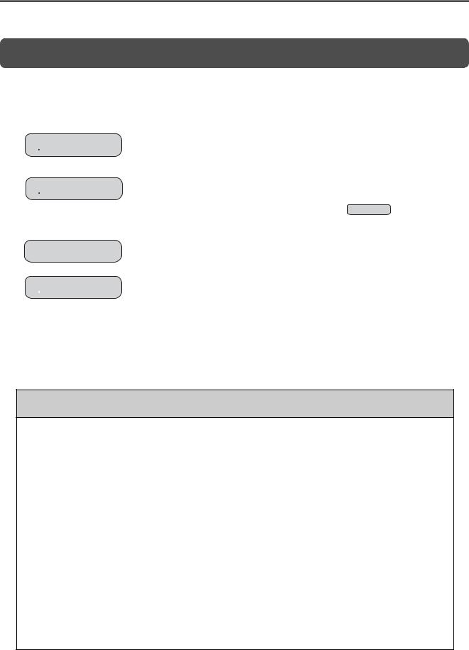
•Always check to confirm the paths of axes when any of the following axis movement instructions are used in programs to ensure that the system operates safely.
•Positioning (MOV)
•Linear Interpolation (MVS)
•Circular Interpolation (MCC or MCW)
•Helical Interpolation (MCC or MCW)
•Set-time Positioning (MVT)
•Linear Interpolation with Skip Function (SKP)
•Zero Point Return (ZRN)
•External Positioning (EXM)
Example |
Axis 3 |
|
Each axis is moved independently |
End position |
|
at rapid traverse speed. |
|
|
Axis 3 |
Positioning operation |
|
|
|
|
|
|
Axis 1 |
Axis 1 |
|
|
Current position |
|
|
Axis 2
Axis 2
Example of Basic Path for Positioning (MOV) Instruction
There is a risk of injury or device damage.
•The same coordinate word will create a completely different travel operation in Absolute Mode and in Incremental Mode. Make sure that the ABS and INC instructions are used correctly before you start operation.
There is a risk of injury or device damage.
•The travel path for the Positioning (MOV) instructions will not necessarily be a straight line. Check to confirm the paths of the axis when this instruction is used in programs to ensure that the system operates safely.
There is a risk of injury or device damage.
•The Linear Interpolation (MVS) instruction can be used on both linear axes and rotary axes. However, if a rotary axis is included, the linear interpolation path will not necessarily be a straight line. Check to confirm the paths of the axis when this instruction is used in programs to ensure that the system operates safely.
There is a risk of injury or device damage.
•The linear interpolation for the Helical Interpolation (MCW and MCC) instructions can be used for both linear axes and rotary axes. However, depending on how the linear axis is taken, the path of helical interpolation will not be a helix. Check to confirm the paths of the axis when this instruction is used in programs to ensure that the system operates safely.
There is a risk of injury or device damage.
xii
 CAUTION
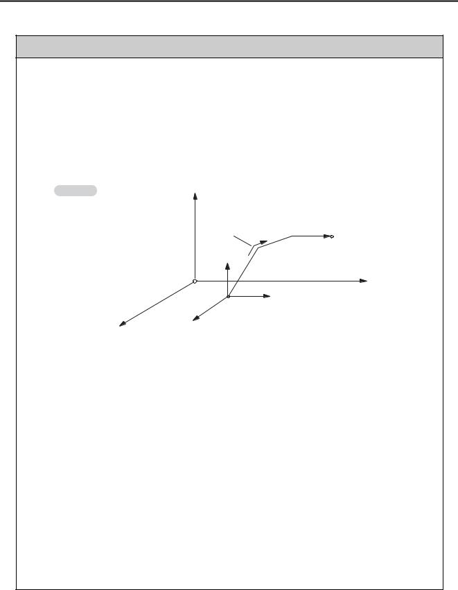
•Unexpected operation may occur if the following coordinate instructions are specified incorrectly: Always confirm that the following instructions are specified correctly before you begin operation.
•Absolute Mode (ABS)
•Incremental Mode (INC)
•Current Position Set (POS)
Example |
Axis 2 |
|
Axis 2 |
|
|
|
|
|
|
(Axis 1) |
Current |
|
|
position |
|
|
(Axis 2) |
|
(0, 0) Working coordinate |
Axis 1 |
|
system |
|
|
Axis 1 |
|
|
(0, 0) Machine coordinate system |
|
|
|
Example of Working Coordinate System Created with the Set Current Position (POS) Instruction
There is a risk of injury or device damage.
•The Set Current Position (POS) Instruction creates a new working coordinate system. Therefore, unexpected operation may occur if the POS instruction is specified incorrectly. When you use the POS instruction, always confirm that the working coordinate system is in the correct position before you begin operation.
There is a risk of injury or device damage.
•The Move on Machine Coordinates (MVM) instruction temporarily performs positioning to a coordinate position in the machine coordinate system. Therefore, unexpected operation may occur if the instruction is executed without confirming the zero point position in the machine coordinate system first. When you use the MVM instruction, always confirm that the machine zero point is in the correct position before you begin operation.
There is a risk of injury or device damage.
xiii

Maintenance and Inspection
 CAUTION
•Do not attempt to disassemble or repair the Machine Controller.
There is a risk of electrical shock, injury, or device damage.
•Do not change any wiring while power is being supplied.
There is a risk of electrical shock, injury, or device damage.
•Suitable battery replacement must be performed and it must be performed only by an experienced technician.
There is a risk of electrical shock, injury, or device damage.
•Replace the Battery only while power is supplied to the Machine Controller.
Replacing the Battery while the power supply to the Machine Controller is turned OFF may result in loss of the data stored in memory in the Machine Controller.
•When you replace the Battery, do not touch the electrodes of the Battery.
There is a risk of electrostatic discharge failure.
•Do not forget to perform the following tasks when you replace the CPU Unit/CPU Module:
•Back up all programs and parameters from the CPU Unit/CPU Module that is being replaced.
•Transfer all saved programs and parameters to the new CPU Unit/CPU Module.
If you operate the CPU Unit/CPU Module without transferring this data, unexpected operation may occur. There is a risk of injury or device damage.
•Do not touch the heat sink on the CPU Unit/CPU Module while the power supply is turned ON or for a sufficient period of time after the power supply is turned OFF.
The heat sink may be very hot, and there is a risk of burn injury.
Disposal
 CAUTION
•Dispose of the Machine Controller as general industrial waste.
•Observe all local laws and ordinances when you dispose of used Batteries.
Other General Precautions
Observe the following general precautions to ensure safe application.
•The products shown in the illustrations in this manual are sometimes shown without covers or protective guards. Always replace the cover or protective guard as specified first, and then operate the products in accordance with the manual.
•The illustrations that are presented in this manual are typical examples and may not match the product you received.
•If the manual must be ordered due to loss or damage, inform your nearest Yaskawa representative or one of the offices listed on the back of this manual.
xiv

Warranty
Details of Warranty
Warranty Period
The warranty period for a product that was purchased (hereinafter called “delivered product”) is one year from the time of delivery to the location specified by the customer or 18 months from the time of shipment from the Yaskawa factory, whichever is sooner.
Warranty Scope
Yaskawa shall replace or repair a defective product free of charge if a defect attributable to Yaskawa occurs during the warranty period above. This warranty does not cover defects caused by the delivered product reaching the end of its service life and replacement of parts that require replacement or that have a limited service life.
This warranty does not cover failures that result from any of the following causes.
•Improper handling, abuse, or use in unsuitable conditions or in environments not described in product catalogs or manuals, or in any separately agreed-upon specifications
•Causes not attributable to the delivered product itself
•Modifications or repairs not performed by Yaskawa
•Abuse of the delivered product in a manner in which it was not originally intended
•Causes that were not foreseeable with the scientific and technological understanding at the time of shipment from Yaskawa
•Events for which Yaskawa is not responsible, such as natural or human-made disasters
Limitations of Liability
•Yaskawa shall in no event be responsible for any damage or loss of opportunity to the customer that arises due to failure of the delivered product.
•Yaskawa shall not be responsible for any programs (including parameter settings) or the results of program execution of the programs provided by the user or by a third party for use with programmable Yaskawa products.
•The information described in product catalogs or manuals is provided for the purpose of the customer purchasing the appropriate product for the intended application. The use thereof does not guarantee that there are no infringements of intellectual property rights or other proprietary rights of Yaskawa or third parties, nor does it construe a license.
•Yaskawa shall not be responsible for any damage arising from infringements of intellectual property rights or other proprietary rights of third parties as a result of using the information described in catalogs or manuals.
xv

Suitability for Use
•It is the customer’s responsibility to confirm conformity with any standards, codes, or regulations that apply if the Yaskawa product is used in combination with any other products.
•The customer must confirm that the Yaskawa product is suitable for the systems, machines, and equipment used by the customer.
•Consult with Yaskawa to determine whether use in the following applications is acceptable. If use in the application is acceptable, use the product with extra allowance in ratings and specifications, and provide safety measures to minimize hazards in the event of failure.
•Outdoor use, use involving potential chemical contamination or electrical interference, or use in conditions or environments not described in product catalogs or manuals
•Nuclear energy control systems, combustion systems, railroad systems, aviation systems, vehicle systems, medical equipment, amusement machines, and installations subject to separate industry or government regulations
•Systems, machines, and equipment that may present a risk to life or property
•Systems that require a high degree of reliability, such as systems that supply gas, water, or electricity, or systems that operate continuously 24 hours a day
•Other systems that require a similar high degree of safety
•Never use the product for an application involving serious risk to life or property without first ensuring that the system is designed to secure the required level of safety with risk warnings and redundancy, and that the Yaskawa product is properly rated and installed.
•The circuit examples and other application examples described in product catalogs and manuals are for reference. Check the functionality and safety of the actual devices and equipment to be used before using the product.
•Read and understand all use prohibitions and precautions, and operate the Yaskawa product correctly to prevent accidental harm to third parties.
Specifications Change
The names, specifications, appearance, and accessories of products in product catalogs and manuals may be changed at any time based on improvements and other reasons. The next editions of the revised catalogs or manuals will be published with updated code numbers. Consult with your Yaskawa representative to confirm the actual specifications before purchasing a product.
xvi

 Contents
About this Manual. . . . . . . . . . . . . . . . . . . . . . . . . . . . . . . . . . . . . . . . . . . . . . . . . . . . . . . . . iii Using this Manual. . . . . . . . . . . . . . . . . . . . . . . . . . . . . . . . . . . . . . . . . . . . . . . . . . . . . . . . . iii Related Manuals . . . . . . . . . . . . . . . . . . . . . . . . . . . . . . . . . . . . . . . . . . . . . . . . . . . . . . . . . v Safety Precautions . . . . . . . . . . . . . . . . . . . . . . . . . . . . . . . . . . . . . . . . . . . . . . . . . . . . . . . vii Warranty . . . . . . . . . . . . . . . . . . . . . . . . . . . . . . . . . . . . . . . . . . . . . . . . . . . . . . . . . . . . . . . xv
1 Overview of Troubleshooting
1.1 Basic Troubleshooting Procedure. . . . . . . . . . . . . . . . . . . . . . . . . . . . . . .1-2 1.2 Checking for Errors. . . . . . . . . . . . . . . . . . . . . . . . . . . . . . . . . . . . . . . . . . 1-3
2 Troubleshooting with Indicators and Displays
2.1 Power Indicators. . . . . . . . . . . . . . . . . . . . . . . . . . . . . . . . . . . . . . . . . . . . 2-2
Power Supply Unit Indicators (MP3200) . . . . . . . . . . . . . . . . . . . . . . . . . . . . . . . . . . . . . 2-2
Base Unit Indicators (MP3300) . . . . . . . . . . . . . . . . . . . . . . . . . . . . . . . . . . . . . . . . . . . . 2-2
2.2 CPU Unit/CPU Module Indicators and Display. . . . . . . . . . . . . . . . . . . . . 2-3
Status Indicators. . . . . . . . . . . . . . . . . . . . . . . . . . . . . . . . . . . . . . . . . . . . . . . . . . . . . . . . 2-3
Display . . . . . . . . . . . . . . . . . . . . . . . . . . . . . . . . . . . . . . . . . . . . . . . . . . . . . . . . . . . . . . . 2-7
USB Status Indicator . . . . . . . . . . . . . . . . . . . . . . . . . . . . . . . . . . . . . . . . . . . . . . . . . . . 2-15
MECHATROLINK-III Status Indicators . . . . . . . . . . . . . . . . . . . . . . . . . . . . . . . . . . . . . . 2-16
Ethernet Connector Indicators . . . . . . . . . . . . . . . . . . . . . . . . . . . . . . . . . . . . . . . . . . . . 2-17
2.3 Rack Expansion Interface Unit Indicators. . . . . . . . . . . . . . . . . . . . . . . . 2-18
3 Troubleshooting using the System Monitor
3.1 Overview of the System Monitor. . . . . . . . . . . . . . . . . . . . . . . . . . . . . . . .3-2
3.2 Troubleshooting Errors with the System Monitor . . . . . . . . . . . . . . . . . . . 3-3
System Errors. . . . . . . . . . . . . . . . . . . . . . . . . . . . . . . . . . . . . . . . . . . . . . . . . . . . . . . . . . 3-3 Scan Time Exceeded . . . . . . . . . . . . . . . . . . . . . . . . . . . . . . . . . . . . . . . . . . . . . . . . . . . . 3-4 Investigating Operation Errors . . . . . . . . . . . . . . . . . . . . . . . . . . . . . . . . . . . . . . . . . . . . . 3-5 Investigating I/O Errors. . . . . . . . . . . . . . . . . . . . . . . . . . . . . . . . . . . . . . . . . . . . . . . . . . . 3-8
4 Troubleshooting Communications and Motion Control
4.1 Troubleshooting Ethernet Communications . . . . . . . . . . . . . . . . . . . . . . . 4-2
Checking Ethernet Cables . . . . . . . . . . . . . . . . . . . . . . . . . . . . . . . . . . . . . . . . . . . . . . . . 4-4
Checking the Ethernet Communications Mode . . . . . . . . . . . . . . . . . . . . . . . . . . . . . . . . 4-4
Troubleshooting Quick Reference . . . . . . . . . . . . . . . . . . . . . . . . . . . . . . . . . . . . . . . . . . 4-5
xvii

4.2 Troubleshooting Motion Errors . . . . . . . . . . . . . . . . . . . . . . . . . . . . . . . . .4-7
Troubleshooting Motion Errors. . . . . . . . . . . . . . . . . . . . . . . . . . . . . . . . . . . . . . . . . . . . . .4-8 Checking Status and Alarms of a Reference-type SERVOPACK
with MECHATROLINK-III Communications . . . . . . . . . . . . . . . . . . . . . . . . . . . . . . . . . . . 4-21
5 Troubleshooting Programming and Debugging
5.1 Troubleshooting Motion Program Alarms . . . . . . . . . . . . . . . . . . . . . . . . .5-2
Checking for Motion Program Alarms . . . . . . . . . . . . . . . . . . . . . . . . . . . . . . . . . . . . . . . .5-2
Structure of Motion Program Alarms . . . . . . . . . . . . . . . . . . . . . . . . . . . . . . . . . . . . . . . . .5-5
Motion Program Alarm Codes . . . . . . . . . . . . . . . . . . . . . . . . . . . . . . . . . . . . . . . . . . . . . .5-6
5.2 Troubleshooting Message Communications. . . . . . . . . . . . . . . . . . . . . .5-10
Checking the Switch Settings . . . . . . . . . . . . . . . . . . . . . . . . . . . . . . . . . . . . . . . . . . . . .5-13 Message Communications Errors . . . . . . . . . . . . . . . . . . . . . . . . . . . . . . . . . . . . . . . . . .5-14 Communications Stopped during Message Communications . . . . . . . . . . . . . . . . . . . . .5-36 Other Problems during Message Communications . . . . . . . . . . . . . . . . . . . . . . . . . . . . . 5-38
6 Troubleshooting Connections with the MPE720
6.1 Troubleshooting Flowchart When the MPE720 Cannot Go Online with the Machine Controller . .6-2
6.2 Checking for Errors . . . . . . . . . . . . . . . . . . . . . . . . . . . . . . . . . . . . . . . . . .6-3
Connection Errors . . . . . . . . . . . . . . . . . . . . . . . . . . . . . . . . . . . . . . . . . . . . . . . . . . . . . . .6-3 Communications Errors . . . . . . . . . . . . . . . . . . . . . . . . . . . . . . . . . . . . . . . . . . . . . . . . . . . 6-3 Model Errors . . . . . . . . . . . . . . . . . . . . . . . . . . . . . . . . . . . . . . . . . . . . . . . . . . . . . . . . . . . 6-4
6.3 Checking the IP Address of the PC . . . . . . . . . . . . . . . . . . . . . . . . . . . . .6-5 6.4 Checking the Communications Settings . . . . . . . . . . . . . . . . . . . . . . . . . .6-7 6.5 Checking the Communications Platform. . . . . . . . . . . . . . . . . . . . . . . . .6-10 6.6 Communications Timeout Errors . . . . . . . . . . . . . . . . . . . . . . . . . . . . . .6-12
7 Troubleshooting System Errors
7.1 Overall Configuration of the System Registers . . . . . . . . . . . . . . . . . . . . .7-2 7.2 Viewing the Contents of the System Registers. . . . . . . . . . . . . . . . . . . . .7-4 7.3 Troubleshooting for the ERR Indicator . . . . . . . . . . . . . . . . . . . . . . . . . . .7-5 7.4 Troubleshooting for the ALM Indicator . . . . . . . . . . . . . . . . . . . . . . . . . . .7-6
xviii

7.5 System Register Configuration and Error Status . . . . . . . . . . . . . . . . . . . 7-7
CPU System Status . . . . . . . . . . . . . . . . . . . . . . . . . . . . . . . . . . . . . . . . . . . . . . . . . . . . . 7-7 System Error Status . . . . . . . . . . . . . . . . . . . . . . . . . . . . . . . . . . . . . . . . . . . . . . . . . . . . . 7-9 User Operation Error Status in Ladder Programs . . . . . . . . . . . . . . . . . . . . . . . . . . . . . .7-11 System Service Execution Status. . . . . . . . . . . . . . . . . . . . . . . . . . . . . . . . . . . . . . . . . . 7-14 System I/O Error Status . . . . . . . . . . . . . . . . . . . . . . . . . . . . . . . . . . . . . . . . . . . . . . . . . 7-15 Security Status . . . . . . . . . . . . . . . . . . . . . . . . . . . . . . . . . . . . . . . . . . . . . . . . . . . . . . . . 7-15 USB-related System Status . . . . . . . . . . . . . . . . . . . . . . . . . . . . . . . . . . . . . . . . . . . . . . 7-16 Message Relaying Status. . . . . . . . . . . . . . . . . . . . . . . . . . . . . . . . . . . . . . . . . . . . . . . . 7-16 Error Status for Individual Products . . . . . . . . . . . . . . . . . . . . . . . . . . . . . . . . . . . . . . . . 7-17 Interrupt Status . . . . . . . . . . . . . . . . . . . . . . . . . . . . . . . . . . . . . . . . . . . . . . . . . . . . . . . . 7-34 Module Information. . . . . . . . . . . . . . . . . . . . . . . . . . . . . . . . . . . . . . . . . . . . . . . . . . . . . 7-36 MPU-01 System Status . . . . . . . . . . . . . . . . . . . . . . . . . . . . . . . . . . . . . . . . . . . . . . . . . 7-47 Motion Program Execution Information . . . . . . . . . . . . . . . . . . . . . . . . . . . . . . . . . . . . . 7-48 Extended System I/O Error Status . . . . . . . . . . . . . . . . . . . . . . . . . . . . . . . . . . . . . . . . . 7-59 Extended Unit and Module Information . . . . . . . . . . . . . . . . . . . . . . . . . . . . . . . . . . . . . 7-64 Extended System Status . . . . . . . . . . . . . . . . . . . . . . . . . . . . . . . . . . . . . . . . . . . . . . . . 7-69 Extended System Service Execution Status . . . . . . . . . . . . . . . . . . . . . . . . . . . . . . . . . 7-70 Alarm History Information. . . . . . . . . . . . . . . . . . . . . . . . . . . . . . . . . . . . . . . . . . . . . . . . 7-70 Product Information . . . . . . . . . . . . . . . . . . . . . . . . . . . . . . . . . . . . . . . . . . . . . . . . . . . . 7-72 Unit and Rack Information . . . . . . . . . . . . . . . . . . . . . . . . . . . . . . . . . . . . . . . . . . . . . . . 7-73 Data Logging Execution Status . . . . . . . . . . . . . . . . . . . . . . . . . . . . . . . . . . . . . . . . . . . 7-75 Automatic Reception Status (Ethernet Communications) . . . . . . . . . . . . . . . . . . . . . . . 7-76
8 MP3200/MP3300 Battery Replacement
8.1 MP3200 Battery Replacement . . . . . . . . . . . . . . . . . . . . . . . . . . . . . . . . . 8-2
8.2 MP3300 Battery Replacement . . . . . . . . . . . . . . . . . . . . . . . . . . . . . . . . . 8-5
9 Fan Replacement
Index
Revision History
xix

Overview of |
1 |
|
Troubleshooting |
||
|
This chapter describes the basic troubleshooting and error confirmation procedures.
1.1 Basic Troubleshooting Procedure . . . . . . . . . . . . 1-2 1.2 Checking for Errors . . . . . . . . . . . . . . . . . . . . . . . 1-3
1.1 Basic Troubleshooting Procedure
1.1  Basic Troubleshooting Procedure
When a problem occurs, it is important to recover normal system operation as soon as possible by finding the cause of the problem and taking the necessary measures. The basic troubleshooting procedure is outlined below.
Step 1
Check the following items visually.
•Machine movement, or status if stopped
•Power supply status
•I/O device status
•Wiring conditions
•Status of indicators and display on Units or Modules
•Switch settings (e.g., DIP switches)
•Parameter settings and program contents
Step 2
See if the problem changes when the following operations are performed.
•Stop the Machine Controller.
•Reset the alarms.
•Turn the power supply OFF and ON again.
Step 3
Isolate the location of the problem from the results of steps 1 and 2.
•Inside or outside of the Machine Controller?
•Software or hardware?
•Sequence control or motion control?
•Ethernet communications or MECHATROLINK communications?
1-2
1.2 Checking for Errors
1.2  Checking for Errors
This section describes the errors that can occur when using the Machine Controller, and how to troubleshoot them.
Follow the troubleshooting procedures outlined below if a problem occurs with the Machine Controller.
1. Check the status of the indicators on the Machine Controller.
Information |
Refer to the following sections for details on checking the status of indicators on the Machine Con- |
|
troller. |
|
|
|
|
|
|
2.1 |
Power Indicators (page 2-2) |
|
2.2 |
CPU Unit/CPU Module Indicators and Display (page 2-3) |
2. Connect the MPE720 to the Machine Controller to check the error information.
If the CPU Unit/CPU Module is not functioning properly, check the status of the indicators on the CPU Unit/CPU Module. Then use the MPE720 to check for errors.
•If a system error and a scan time exceeded error have occurred:

 Chapter 3 Troubleshooting using the System Monitor
•If an Ethernet communications error or a motion control error has occurred:

 Chapter 4 Troubleshooting Communications and Motion Control
•If an error occurred in a motion program or during message communications:

 Chapter 5 Troubleshooting Programming and Debugging
•If you cannot go online with the MPE720:
Chapter 6 Troubleshooting Connections with the MPE720
•If you want to investigate a system error:

 Chapter 7 Troubleshooting System Errors
Overview of Troubleshooting
1-3

Troubleshooting with
Indicators and Displays
2
This chapter describes troubleshooting procedures with the indicators and the display on the Machine Controller.
2.1 Power Indicators . . . . . . . . . . . . . . . . . . . . . . . . . |
2-2 |
Power Supply Unit Indicators (MP3200) . . . . . . . . . . . . . . . . . 2-2
Base Unit Indicators (MP3300) . . . . . . . . . . . . . . . . . . . . . . . . 2-2
2.2CPU Unit/CPU Module Indicators and Display . . 2-3
Status Indicators . . . . . . . . . . . . . . . . . . . . . . . . . . . . . . . . . . . 2-3
Display . . . . . . . . . . . . . . . . . . . . . . . . . . . . . . . . . . . . . . . . . . 2-7
USB Status Indicator . . . . . . . . . . . . . . . . . . . . . . . . . . . . . . 2-15
MECHATROLINK-III Status Indicators . . . . . . . . . . . . . . . . . 2-16
Ethernet Connector Indicators . . . . . . . . . . . . . . . . . . . . . . . 2-17
2.3 Rack Expansion Interface Unit Indicators . . . . . 2-18
2.1 Power Indicators
Power Supply Unit Indicators (MP3200)
2.1  Power Indicators
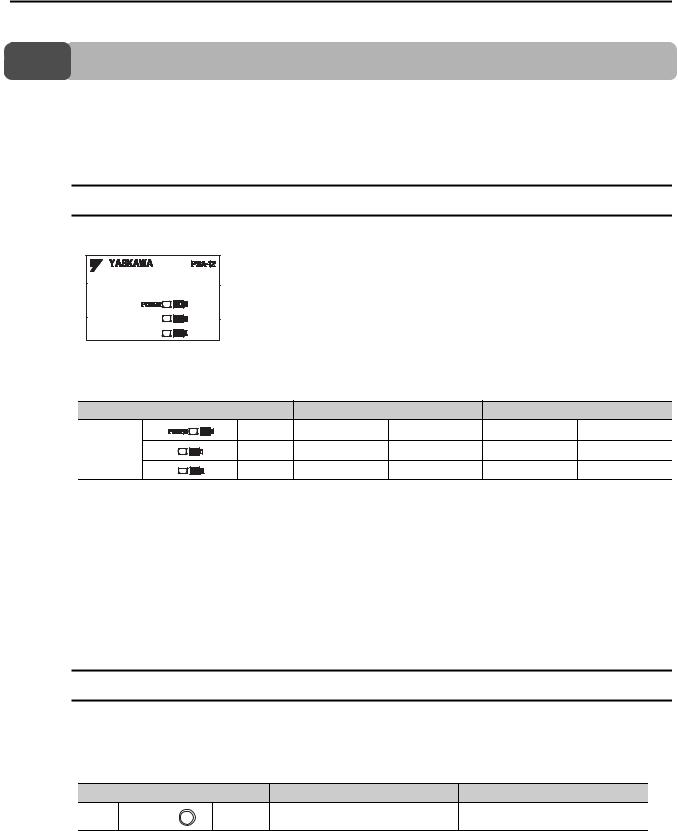
You can check the power supply loading status with the power indicators on the MP3000.
With the MP3200, the indicators are on the Power Supply Unit, and with the MP3300, there is an indicator on the Base Unit. This section describes the power indicators for the MP3200 and MP3300.
Power Supply Unit Indicators (MP3200)
This section describes how to check the load on the Power Supply Unit.
The following table gives the relation between the indicators on the Power Supply Unit and the load on the Power Supply Unit.
|
Load |
|
Normal |
|
Error |
|
Green |
|
|
|
|
Indicators |
Yellow |
|
|
|
|
|
Red |
|
|
|
|
Note: 1. : Lit, : Not lit.
2. The indicators show the status when the Power Supply Unit is turned ON.
Check the status in the above table and perform the actions given below if the power loading status indicates an error.
Load |
Cause |
Correction |
|
The load exceeds the |
• Reduce the number of Optional Modules installed on the Base |
Error |
capacity of the Power Sup- |
Unit. |
|
ply Unit. |
• Reduce the number of Units. |
|
|
|
Base Unit Indicators (MP3300)
With the MP3300, you can check the power supply loading status on the Base Unit.
The following table shows the relation between the load status of the Rack power supply and the indicator on the Power Supply Unit.
|
Load |
|
Normal |
Error |
LED |
POWER |
Green |
|
|
Check the status in the above table and perform the actions given below if the power loading status indicates an error.
Load |
Cause |
Correction |
|
|
The load exceeds the |
Reduce the number of Optional Modules installed on the Base |
|
Error |
capacity of the Power Sup- |
||
Unit. |
|||
|
ply Unit. |
||
|
|
||
|
|
|
2-2

2.2 CPU Unit/CPU Module Indicators and Display
Status Indicators
2.2  CPU Unit/CPU Module Indicators and Display
You can use the indicators on the CPU Unit/CPU Module to check the error status of the CPU Unit/CPU Module.
After you check the error status, the system (S) registers will help you isolate the program location that needs to be corrected.
Refer to the following chapter for details on system registers.
Chapter 7 Troubleshooting System Errors
The CPU Unit/CPU Module has the following display and four types of indicators.
•Display
•Status indicators
•USB status indicator
•MECHATROLINK-III status indicators
•Ethernet status indicators
The error status and error details can be checked using the above display and indicators.
The display and indicators will give you a general idea of what the error is and the system (S) registers will help you isolate the program location that needs to be corrected.
Status Indicators
These indicators show the status of the CPU Unit/CPU Module.
Troubleshooting with Indicators and Displays
2-3

2.2 CPU Unit/CPU Module Indicators and Display
Status Indicators
The patterns of the status indicators are described in the following table.
|
|
|
Indicator Status |
|
|
CPU Unit/CPU |
|
|
|
|
RDY |
RUN |
ALM |
ERR |
BAT |
M_ALM |
|
Description |
|
|
Module Status |
|
|||||||
|
(Green) |
(Green) |
(Red) |
(Red) |
(Red) |
(Red) |
|
|
|
|
|
|
|
||||||
|
|
|
|
|
− |
|
Hardware reset |
Normally, the CPU Unit |
|
|
|
|
|
|
|
|
|
will start within 10 sec- |
|
|
|
|
|
|
− |
|
Initialization |
||
|
|
|
|
|
|
|
|
onds. If more than 10 |
|
|
|
|
|
|
|
|
|
||
|
|
|
|
|
|
|
|
seconds is required, |
|
|
|
|
|
|
|
|
|
there is an error in a user |
|
|
|
|
|
|
|
|
|
program or a hardware |
|
|
|
|
|
|
|
|
|
error. Refer to the fol- |
|
|
|
|
|
|
− |
|
Drawing A is being |
lowing section for infor- |
|
|
executed. |
mation on system errors |
|||||||
|
|
|
|
|
|
|
|||
|
|
|
|
|
|
|
|
and implement correc- |
|
Normal |
|
|
|
|
|
|
|
tions. |
|
|
|
|
|
|
|
|
|
Chapter 7 Trouble- |
|
|
|
|
|
|
|
|
|
|
|
|
|
|
|
|
|
|
|
|
shooting System |
|
|
|
|
|
|
|
|
|
Errors |
|
|
|
|
|
|
|
|
|
|
|
|
|
|
|
|
|
|
• The stop operation |
|
|
|
|
|
|
|
|
|
|
was performed from |
|
|
|
|
|
− |
|
The user programs |
|
the MPE720. |
|
|
|
|
|
|
are stopped (offline |
• This is the status after |
||
|
|
|
|
|
|
|
stop mode). |
|
the STOP switch is |
|
|
|
|
|
|
|
|
|
turned ON. It is not an |
|
|
|
|
|
|
|
|
|
error. |
|
|
|
|
|
|
|
|
|
|
|
|
|
|
|
− |
|
The user programs |
Normal operation is in |
|
|
|
|
|
|
|
are being executed |
|||
|
progress. |
||||||||
|
|
|
|
|
|
|
normally. |
||
|
|
|
|
|
|
|
|
|
|
|
|
|
|
|
|
|
|
|
|
Note: : Not lit, : Lit, : Flashing, −: Any status |
|
|
|
|
Continued on next page. |
||||
|
|
|
|
|
|||||
2-4

Error
2.2 CPU Unit/CPU Module Indicators and Display
Status Indicators
|
|
|
|
|
|
Continued from previous page. |
|||
|
|
Indicator Status |
|
|
CPU Unit/CPU |
|
|
||
|
|
|
|
|
|
||||
|
|
|
|
|
|
|
Description |
||
RDY |
RUN |
ALM |
ERR |
BAT |
M_ALM |
|
|||
Module Status |
|
||||||||
(Green) |
(Green) |
(Red) |
(Red) |
(Red) |
(Red) |
|
|
||
|
|
|
|||||||
|
|
|
|
|
|
|
If the ERR indicator is |
||
|
|
|
|
|
|
|
lit, there is a hardware |
||
|
|
|
|
|
|
|
failure or a user program |
||
|
|
|
|
|
|
|
error. Refer to the fol- |
||
|
|
|
|
|
|
A serious failure |
lowing section for the |
||
|
|
|
|
|
|
corrective actions to take |
|||
error occurred. |
|||||||||
|
|
|
|
|
|
when the ERR indicator |
|||
|
|
|
|
|
|
|
|||
|
|
|
|
|
|
|
is lit. |
||
|
|
|
|
|
|
|
|
7.3 Troubleshooting |
|
|
|
|
|
|
|
|
|
||
|
|
|
|
|
|
|
|
for the ERR Indicator |
|
|
|
|
|
|
|
|
|
(page 7-5) |
|
|
|
|
|
|
|
|
|
|
|
|
|
|
|
|
|
Software Errors: |
|
|
|
|
|
|
|
|
|
Number of Flashes |
|
|
|
|
|
|
|
|
|
2: Machine check |
|
|
|
|
|
|
|
|
|
exception |
|
|
|
|
|
|
|
|
|
3: DSI (writing) |
|
|
|
|
|
|
|
|
|
exception |
|
|
|
|
|
|
|
|
|
4: ISI exception |
|
|
|
|
|
|
|
− |
|
5: Alignment |
|
|
|
exception |
|
|
|||||||
|
|
|
|
|
|
|
|
||
|
|
|
|
|
|
6: DDR DRAM |
|
|
|
|
|
|
|
|
|
memory error |
|
|
|
|
|
|
|
|
|
exception |
|
|
|
|
|
|
|
|
|
7: DTLB excep- |
A hardware failure has |
||
|
|
|
|
|
|
tion |
|||
|
|
|
|
|
|
occurred. Replace the |
|||
|
|
|
|
|
|
8: ITLB excep- |
|||
|
|
|
|
|
|
Unit or Module. |
|||
|
|
|
|
|
|
tion |
|||
|
|
|
|
|
|
|
|
||
|
|
|
|
|
|
|
|
|
|
|
|
|
|
|
|
Hardware Errors: |
|
|
|
|
|
|
|
|
|
Number of Flashes |
|
|
|
|
|
|
|
|
|
2: RAM diagnos- |
|
|
|
|
|
|
|
|
|
tic error |
|
|
|
|
|
|
|
|
|
3: ROM diagnos- |
|
|
|
|
|
|
|
− |
|
tic error |
|
|
|
4: CPU Function |
|
|
|||||||
|
|
|
|
|
|
|
|
||
|
|
|
|
|
|
Module diagnos- |
|
|
|
|
|
|
|
|
|
tic error |
|
|
|
|
|
|
|
|
|
5: FPU Function |
|
|
|
|
|
|
|
|
|
Module diagnos- |
|
|
|
|
|
|
|
|
|
tic error |
|
|
|
|
|
|
|
|
|
|
|
|
|
|
|
|
|
|
|
|
If the M_ALM indica- |
||
|
|
|
|
|
|
|
tor is lit, there is an error |
||
|
|
|
|
|
|
|
in the Motion Control |
||
|
|
|
|
|
|
|
Function Module. Refer |
||
− |
− |
− |
− |
− |
|
Motion error |
to the following section |
||
for details on motion |
|||||||||
|
|
|
|
|
|
|
|||
|
|
|
|
|
|
|
errors. |
||
|
|
|
|
|
|
|
|
4.2 Troubleshooting |
|
|
|
|
|
|
|
|
|
||
|
|
|
|
|
|
|
|
Motion Errors (page |
|
|
|
|
|
|
|
|
4-7) |
||
|
|
|
|
|
|
|
|
Continued on next page. |
|
Troubleshooting with Indicators and Displays
2-5

2.2 CPU Unit/CPU Module Indicators and Display
Status Indicators
|
|
|
|
|
|
|
|
Continued from previous page. |
||
|
|
|
|
|
|
|
|
|
|
|
|
|
|
Indicator Status |
|
|
CPU Unit/CPU |
|
|
|
|
|
RDY |
RUN |
ALM |
ERR |
BAT |
M_ALM |
|
|
Description |
|
|
Module Status |
|
|
|||||||
|
(Green) |
(Green) |
(Red) |
(Red) |
(Red) |
(Red) |
|
|
|
|
|
|
|
|
|
||||||
|
|
|
|
|
|
|
|
|
If the BAT indicator is |
|
|
|
|
|
|
|
|
|
|
lit, the Battery must be |
|
|
|
|
|
|
|
|
|
|
replaced. Refer to the |
|
|
|
|
|
|
|
|
|
|
following section for the |
|
|
− |
− |
− |
− |
|
− |
Battery alarm |
|
Battery replacement pro- |
|
|
|
cedure. |
||||||||
|
|
|
|
|
|
|
|
|
||
|
|
|
|
|
|
|
|
|
|
Chapter 8 |
|
|
|
|
|
|
|
|
|
|
|
|
|
|
|
|
|
|
|
|
|
MP3200/MP3300 |
Alarms |
|
|
|
|
|
|
|
|
|
Battery Replace- |
|
|
|
|
|
|
|
|
|
ment |
|
|
|
|
|
|
|
|
|
|
|
|
|
|
|
|
|
|
|
|
|
|
|
|
|
|
|
|
|
|
|
|
If the ALM indicator is |
|
|
|
|
|
|
|
|
|
|
lit, there is an operation |
|
|
|
|
|
|
|
|
|
|
error or an I/O error. |
|
|
|
|
|
|
|
|
Operation error |
|
Refer to the following |
|
|
|
|
|
|
− |
− |
|
section for the corrective |
||
|
I/O error |
|
actions to take when the |
|||||||
|
|
|
|
|
|
|
|
|||
|
|
|
|
|
|
|
|
|
ALM indicator is lit. |
|
|
|
|
|
|
|
|
|
|
|
7.4 Troubleshooting |
|
|
|
|
|
|
|
|
|
|
|
|
|
|
|
|
|
|
|
|
|
for the ALM Indica- |
|
|
|
|
|
|
|
|
|
|
tor (page 7-6) |
|
|
|
|
|
|
|
|
|
|
|
Note: |
: Not lit, |
: Lit, : |
Flashing, −: |
Any status |
|
|
|
|
|
|
2-6
2.2 CPU Unit/CPU Module Indicators and Display
Display
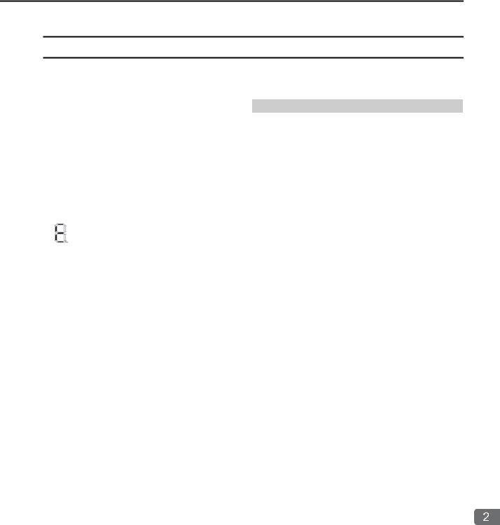
Display
If an error or alarm occurs, details will be displayed on the display. This section describes the display patterns and corresponding errors.
|
|
Display |
Category |
Description |
|
|
|
|
A 3-digit error code is displayed after E, like this: |
|
|
|
|
E001: Watchdog timer error |
|
|
|
|
E051: Module synchronization error |
|
|
|
|
E052: Main CPU Unit system down detected |
|
|
|
|
E061: Unit configuration error on Rack 1 |
|
|
|
|
E062: Unit configuration error on Rack 2 |
|
|
|
|
E063: Unit configuration error on Rack 3 |
|
|
|
|
E064: Unit configuration error on Rack 4 |
|
|
|
|
E065: Unit configuration error on Rack 5 |
|
|
followed by error |
System error |
E066: Unit configuration error on Rack 6 |
|
|
E067: Unit configuration error on Rack 7 |
||
|
|
|
||
code |
|
E070: Unsupported Sub CPU mode |
||
|
|
|
|
|
|
|
|
|
E071: Unsupported Module detected |
|
|
|
|
E080: CPU mode mismatch |
|
|
|
|
E081: CPU stopped for internal temperature error 1 |
|
|
|
|
E082 CPU stopped for internal temperature error 2 |
|
|
|
|
E083: Fan stopped |
|
|
|
|
E090: Hardware error 1 |
|
|
|
|
E091: Hardware error 2 |
|
|
|
|
E092: Hardware error 3 |
|
|
|
|
|
|
|
|
|
Continued on next page. |
Troubleshooting with Indicators and Displays
2-7

2.2 CPU Unit/CPU Module Indicators and Display
Display
|
|
|
|
Continued from previous page. |
|
|
|
|
|
|
|
Display |
Category |
Description |
|
|
|
|
A 3-digit error code is displayed after A, like this: |
|
|
|
|
A001: Operation error in DWG.A |
|
|
|
|
A002: Operation error in DWG.I |
|
|
|
|
A003: Operation error in DWG.H |
|
|
|
|
A005: Operation error in DWG.L |
|
|
|
|
A101: I/O error on Rack 1 |
|
|
|
|
A102: I/O error on Rack 2 |
|
|
|
|
A103: I/O error on Rack 3 |
|
|
|
|
A104: I/O error on Rack 4 |
|
|
|
|
A105: I/O error on Rack 5 |
|
|
|
|
A106: I/O error on Rack 6 |
|
|
|
|
A107: I/O error on Rack 7 |
|
|
|
|
A201: Insufficient power supply capacity warning 1 for |
|
|
|
|
Rack 1 |
|
|
|
|
A205: Insufficient power supply capacity warning 1 for |
|
|
|
|
Rack 5 |
|
|
|
|
A206: Insufficient power supply capacity warning 1 for |
|
|
|
|
Rack 6 |
|
|
|
|
A207: Insufficient power supply capacity warning 1 for |
|
|
|
|
Rack 7 |
|
|
|
|
A211: Insufficient power supply capacity warning 2 for |
|
|
|
|
Rack 1 |
|
|
|
|
A215: Insufficient power supply capacity warning 2 for |
|
|
|
|
Rack 5 |
|
|
|
|
A216: Insufficient power supply capacity warning 2 for |
|
|
|
|
|
|
|
followed by error |
Alarm |
Rack 6 |
|
|
A217: Insufficient power supply capacity warning 2 for |
||
|
|
|
||
code |
|
|||
|
Rack 7 |
|||
|
|
|
|
|
|
|
|
|
A221: Power interruption detected on Expansion Rack 1 |
|
|
|
|
A225: Power interruption detected on Expansion Rack 5 |
|
|
|
|
A226: Power interruption detected on Expansion Rack 6 |
|
|
|
|
A227: Power interruption detected on Expansion Rack 7 |
|
|
|
|
A230: Hardware error 4 |
|
|
|
|
A240: Fan stopped |
|
|
|
|
A241: Internal temperature rise detected |
|
|
|
|
A301: USB memory write error |
|
|
|
|
A302: USB memory read error |
|
|
|
|
A303: Security error |
|
|
|
|
A305: Folder for batch loading does not exist. |
|
|
|
|
A306: Load file model mismatch error |
|
|
|
|
A307: Loading error due to program write protection |
|
|
|
|
A308: Load file write error |
|
|
|
|
A309: Save to flash memory error |
|
|
|
|
A30A:Save file read error |
|
|
|
|
A30B: No USB memory device |
|
|
|
|
A370: Log folder creation error |
|
|
|
|
A371: Log file creation error |
|
|
|
|
A372: Log file writing error |
|
|
|
|
A401: M-III restrictions error |
|
|
|
|
A402: Error in MPU-01 |
|
|
|
|
A403: Error in Sub CPU |
|
|
|
|
|
|
|
|
|
Continued on next page. |
2-8
Loading...