


 MP3300iec
Machine Controller
Hardware Manual
Type: MP3300iec
To properly use the product, read this manual thoroughly and retain for easy reference, inspection,
and maintenance. Ensure the end user receives this manual.
YAI-SIA-IEC-7

Table of Contents
1. Basic Units . . . . . . . . . . . . . . . . . . . . . . . . . . . . . . . . . . . . . . . . . . . . . . . . . . . . . . . . . . . . . 5 2. System Configuration Example . . . . . . . . . . . . . . . . . . . . . . . . . . . . . . . . . . . . . . . . . . . . 6 3. Component Part Numbers. . . . . . . . . . . . . . . . . . . . . . . . . . . . . . . . . . . . . . . . . . . . . . . . . 7 4. Base Units. . . . . . . . . . . . . . . . . . . . . . . . . . . . . . . . . . . . . . . . . . . . . . . . . . . . . . . . . . . . . . 8 5. CPU Specifications . . . . . . . . . . . . . . . . . . . . . . . . . . . . . . . . . . . . . . . . . . . . . . . . . . . . . 10 6. Installation and Usage Conditions . . . . . . . . . . . . . . . . . . . . . . . . . . . . . . . . . . . . . . . . . 13 7. Base Unit Specifications . . . . . . . . . . . . . . . . . . . . . . . . . . . . . . . . . . . . . . . . . . . . . . . . . 15 8. Switches . . . . . . . . . . . . . . . . . . . . . . . . . . . . . . . . . . . . . . . . . . . . . . . . . . . . . . . . . . . . . . 16 9. Display and Indicators . . . . . . . . . . . . . . . . . . . . . . . . . . . . . . . . . . . . . . . . . . . . . . . . . . .17 10. Self-Configuration . . . . . . . . . . . . . . . . . . . . . . . . . . . . . . . . . . . . . . . . . . . . . . . . . . . . . 19 11. MECHATROLINK-III Specifications. . . . . . . . . . . . . . . . . . . . . . . . . . . . . . . . . . . . . . . . 20 12. MECHATROLINK-III Network Topologies. . . . . . . . . . . . . . . . . . . . . . . . . . . . . . . . . . . 21 13. MECHATROLINK-III Synchronization between Modules . . . . . . . . . . . . . . . . . . . . . . 24 14. Devices Connectable via MECHATROLINK-III. . . . . . . . . . . . . . . . . . . . . . . . . . . . . . . 25 15. Connecting the RLY OUT Connector . . . . . . . . . . . . . . . . . . . . . . . . . . . . . . . . . . . . . . 26 16. Ethernet Connector Details . . . . . . . . . . . . . . . . . . . . . . . . . . . . . . . . . . . . . . . . . . . . . . 27 17. Option Module - AI-01 (Analog Input) Module . . . . . . . . . . . . . . . . . . . . . . . . . . . . . . 30 18. Option Module - AO-01 (Analog Output) Module . . . . . . . . . . . . . . . . . . . . . . . . . . . . 36 19. Option Module - DO-01 (Digital Output) Module . . . . . . . . . . . . . . . . . . . . . . . . . . . . . 39 20. Option Module - LIO-01/02 Module . . . . . . . . . . . . . . . . . . . . . . . . . . . . . . . . . . . . . . . . 43 21. Option Module - LIO-04/05 Modules . . . . . . . . . . . . . . . . . . . . . . . . . . . . . . . . . . . . . . . 51 22. Option Module - LIO-06 Module . . . . . . . . . . . . . . . . . . . . . . . . . . . . . . . . . . . . . . . . . . 63 23. Option Module – 218IF-Y1 . . . . . . . . . . . . . . . . . . . . . . . . . . . . . . . . . . . . . . . . . . . . . . . 73 24. Terminal Block Kit CBK-U-MP2A-xx. . . . . . . . . . . . . . . . . . . . . . . . . . . . . . . . . . . . . . . 75 25. Terminal Block Kit CBK-U-MP2B-xx. . . . . . . . . . . . . . . . . . . . . . . . . . . . . . . . . . . . . . . 76 26. Terminal Block Kit CBK-U-MP2C-xx. . . . . . . . . . . . . . . . . . . . . . . . . . . . . . . . . . . . . . . 77 27. Cable Shielding, Segregation and Noise Immunity . . . . . . . . . . . . . . . . . . . . . . . . . . 78
Copyright © 2014 YASKAWA AMERICA, INC.
All rights reserved. No part of this publication may be reproduced, stored in a retrieval system, or transmitted, in any form, or by any means, mechanical, electronic, photocopying, recording, or otherwise, without the prior written permission of Yaskawa. No patent liability is assumed with respect to the use of the information contained herein. Moreover, because Yaskawa is constantly striving to improve its high-quality products, the information contained in this manual is subject to change without notice. Every precaution has been taken in the preparation of this manual. Nevertheless, Yaskawa assumes no responsibility for errors or omissions. Neither is any liability assumed for damages resulting from the use of the information contained in this publication.
YASKAWA America, Inc. MP3300iec Hardware Manual YAI-SIA-IEC-7 |
3 |

4 |
YASKAWA America, Inc. MP3300iec Hardware Manual YAI-SIA-IEC-7 |
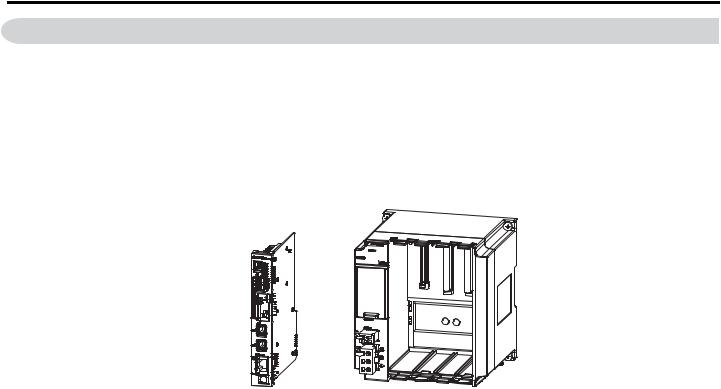
1 Basic Units
1 Basic Units
“Basic Unit” is a collective term that refers to the modules in the following table.
Unit Name |
Primary Function |
|
CPU Module |
Stores the module definitions and programs, and interprets the programs. The CPU Module also controls the |
|
Optional Modules. |
||
|
||
Base Unit |
Contains the power supply and provides the backplane to which Modules are mounted. |
The Basic Modules are typically connected as shown in the following examples.
+
CPU Module |
Base Unit |
YASKAWA America, Inc. MP3300iec Hardware Manual YAI-SIA-IEC-7 |
5 |
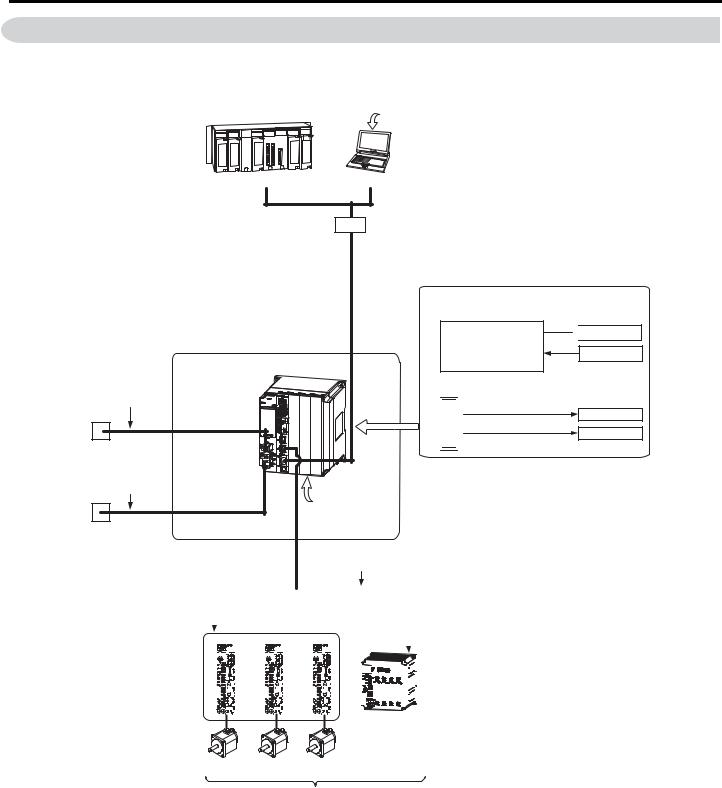
2 System Configuration Example
2 System Configuration Example
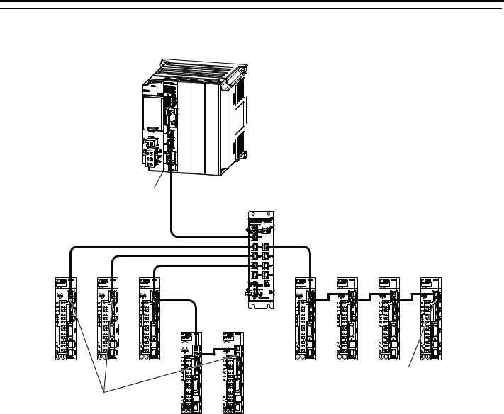
The following figure shows a typical system configuration.
 MotionWorks IEC version 3.0.0 or higher
|
|
|
|
|
|
|
|
|
|
|
|
|
|
|
|
|
|
|
|
|
|
|
|
|
|
|
|
|
|
|
|
|
|
|
|
|
|
|
|
|
Another PLC |
PC |
|||||
HUB
Ethernet communications cables
MP3300
RLYOUT connector cable
Battery
24-VDC power supply, AC power supply, or status monitoring device
Power supply cable
24-VDC power supply or AC power supply
MECHATROLINK-III
Front cover for unused slot
MECHATROLINK-III Cable
|
|
|
|
|
|
|
|
|
|
|
|
|
|
|
|
|
|
|
|
|
|
|
|
|
|
SERVOPACK with |
|
|
|
|
|
|
|
|
|
|
|
|
|
|
|
|
|
|
|
|
|
|
|
|
|
MECHATROLINK-III |
|
|
|
|
|
|
|
|
|
|
|
|
|
|
|
|
|
|
|
|
|
|
|
|
|
Communications |
|
I/O |
Module with |
||||||||||||||||||||||
|
|
|
MECHATROLINK-III |
||||||||||||||||||||||
|
|
|
|||||||||||||||||||||||
|
|
|
|
Communications |
|||||||||||||||||||||
|
|
|
|
|
|
|
|
|
|
|
|
|
|
|
|
|
|
|
|
|
|
|
|
|
|
|
|
|
|
|
|
|
|
|
|
|
|
|
|
|
|
|
|
|
|
|
|
|
|
|
|
|
|
|
|
|
|
|
|
|
|
|
|
|
|
|
|
|
|
|
|
|
|
|
|
|
|
|
|
|
|
|
|
|
|
|
|
|
|
|
|
|
|
|
|
|
|
|
|
|
|
|
|
|
|
|
|
|
|
|
|
|
|
|
|
|
|
|
|
|
|
|
|
|
|
|
|
|
|
|
|
|
|
|
|
|
|
|
|
|
|
|
|
|
|
|
|
|
|
|
|
|
|
|
|
|
|
|
|
|
|
|
|
|
|
|
|
|
|
|
|
|
|
|
|
|
|
|
|
|
|
I/O
Servomotor Servomotor Servomotor
Optional Modules
I/O Modules
LIO-01 |
LIO-02 |
LIO-04 |
LIO-05 |
LIO-06 |
DO-01 |
AI-01 |
AO-01 |
|
|
|
|
|
|
|
|
Communications Modules

 218IF-Y1

Up to 62 stations, including I/O
 External outputs
External inputs
RS-232C
Ethernet
6 |
YASKAWA America, Inc. MP3300iec Hardware Manual YAI-SIA-IEC-7 |

3 Component Part Numbers
3 Component Part Numbers
|
|
System Components |
|
Type |
Part Number |
Description |
|
|
PMC-U-MP33004 |
CPU, MP3300, 4 axis, 400 MHz, 4MB SRAM |
|
|
|
|
|
|
PMC-U-MP33008 |
CPU, MP3300, 8 axis, 400 MHz, 4MB SRAM |
|
CPU |
|
|
|
PMC-U-MP33020 |
CPU, MP3300, 20 axis, 400 MHz, 4MB SRAM |
||
|
|
|
|
|
PMC-U-MP33320 |
CPU, MP3300, 20 axis, 800 MHz, 8MB SRAM |
|
|
|
|
|
|
PMC-U-MP33332 |
CPU, MP3300, 32 axis, 800 MHz, 8MB SRAM |
|
|
|
|
|
|
JEPMC-BU3304-E |
Base Unit with DC Power Supply, 1 Slot, MP3300iec |
|
|
|
|
|
Base Unit |
JEPMC-BU3303-E |
Base Unit with DC Power Supply, 3 Slots, MP3300iec |
|
|
|
||
JEPMC-BU3302-E |
Base Unit with DC Power Supply, 8 Slots, MP3300iec |
||
|
|||
|
|
|
|
|
JEPMC-BU3301-E |
Base Unit with AC Power Supply, 8 Slots, MP3300iec |
|
|
|
|
|
|
JAPMC-AN2300 |
Analog Inputs (AI-01) |
|
|
JAPMC-AN2310-E |
Analog Outputs (AO-01) |
|
|
JAPMC-DO2300 |
Digital Output Module (DO-01) |
|
|
JAPMC-IO2300-E |
Digital I/O Module (LIO-01) |
|
Option Card |
JAPMC-IO2301-E |
Digital I/O Module (LIO-02) |
|
|
JAPMC-IO2303 |
Digital I/O Module (LIO-04) |
|
|
JAPMC-IO2304 |
Digital I/O Module (LIO-05) |
|
|
JAPMC-IO2305-E |
Digital Multi-Function I/O Module (LIO-06) |
|
|
JAPMC-CM2301-E |
Ethernet & RS232C Communication (218IF-Y1) |
|
|
JEPMC-MT2000-E |
HUB, MECHATROLINK-III NETWORK, 8 SLAVE PORTS |
|
MECHATROLINK |
JEPMC-MT2020-E |
ADAPTER, ETHERNET TO MECHATROLINK |
|
JEPMC-MTD2310-E |
I/O MODULE, MECHATROLINK NETWORK, 64 IN, 64 OUT |
||
Network |
|||
JEPMC-MTA2900-E |
ANALOG MODULE, MECHATROLINK NETWORK, 8 INPUT |
||
|
|||
|
JEPMC-MTA2910-E |
ANALOG MODULE, MECHATROLINK NETWORK, 4 OUTPUT |
|
|
JEPMC-W6012-A2-E |
MECHATROLINK-III CABLE, 0.2 M |
|
|
JEPMC-W6012-A5-E |
MECHATROLINK-III CABLE, 0.5 M |
|
|
JEPMC-W6012-01-E |
MECHATROLINK-III CABLE, 1.0 M |
|
|
JEPMC-W6012-02-E |
MECHATROLINK-III CABLE, 2.0 M |
|
|
JEPMC-W6012-03-E |
MECHATROLINK-III CABLE, 3.0 M |
|
MECHATROLINK |
JEPMC-W6012-04-E |
MECHATROLINK-III CABLE, 4.0 M |
|
Cables |
JEPMC-W6012-05-E |
MECHATROLINK-III CABLE, 5.0 M |
|
|
JEPMC-W6012-10-E |
MECHATROLINK-III CABLE, 10 M |
|
|
JEPMC-W6012-20-E |
MECHATROLINK-III CABLE, 20 M |
|
|
JEPMC-W6012-30-E |
MECHATROLINK-III CABLE, 30 M |
|
|
JEPMC-W6012-40-E |
MECHATROLINK-III CABLE, 40 M |
|
|
JEPMC-W6012-50-E |
MECHATROLINK-III CABLE, 50 M |
|
|
JEPMC-BA3001 |
Replacement Battery |
|
Accessories |
JEPMC-OP2300 |
Option Slot Cover |
|
JEPMC-OP3001 |
Replacement Power Supply Side Cover |
||
|
|||
|
JEPMC-OP3002 |
Replacement Option Base Side Cover |
YASKAWA America, Inc. MP3300iec Hardware Manual YAI-SIA-IEC-7 |
7 |
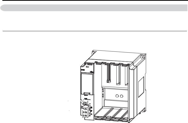
4 Base Units
4 Base Units
The Base Unit provides the backplane to which Modules are mounted and supplies the required power to the Modules. There are three models of Base Units, a one-slot model, a three-slot model, and an eight-slot model. This section shows the appearance and part names of the Base Unit and describes the connector.
Appearance and Part Names
Figure 1 illustrates the appearance of the Base Unit and a part name.
RLYOUT connector 


Power connector 


Figure 1 Base Unit
8 |
YASKAWA America, Inc. MP3300iec Hardware Manual YAI-SIA-IEC-7 |
4 Base Units
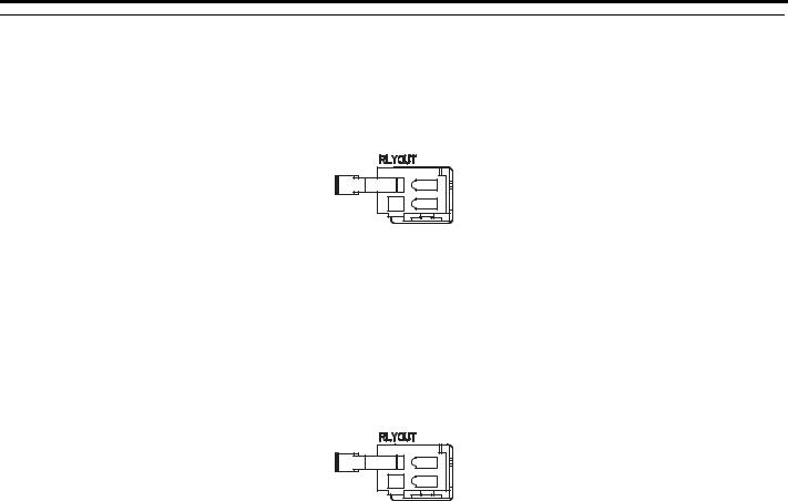
Connector
The Base Unit has two connectors: an RLYOUT connector and a power connector.
RLYOUT Connector
The RLYOUT connector outputs the status of the CPU Module.
Figure 2 RLYOUT Connector Model: 734-302
Pin Assignments
No. |
Signal Label |
Description |
1 |
OUT |
Normal operation: Circuit closed. |
2 |
OUT |
Error: Circuit open. |
Power Connector
Connect the power supply to this connector.
Figure 3 RLYOUT Connector Model: 734-302
Type |
Model |
Color |
|
DC power supply |
4-2013522-3 |
White |
|
Pin Assignments |
|
|
|
|
|
|
|
No. |
Signal Label |
Description |
|
3 |
24 VDC |
Power input wire for 24 VDC |
|
2 |
0 VDC |
Power input wire for 0 VDC |
|
1 |
FG |
Connects to the frame ground. (Ground to |
|
100 W max.) |
|||
|
|
YASKAWA America, Inc. MP3300iec Hardware Manual YAI-SIA-IEC-7 |
9 |

5 CPU Specifications
5 CPU Specifications
The hardware specifications of the CPU Unit are given in the following table.
Item |
CPU Specification |
|
Model |
PMC-U-MP330xx |
|
|
• PMC-U-MP33004: CPU, MP3300, 4 axis, 400 MHz, 4MB SRAM |
|
Part Number: Description |
• PMC-U-MP33008: CPU, MP3300, 8axis, 400 MHz, 4MB SRAM |
|
• PMC-U-MP33020: CPU, MP3300, 20 axis, 400 MHz, 4MB SRAM |
||
|
• PMC-U-MP33320: CPU, MP3300, 20 axis, 800 MHz, 8MB SRAM |
|
|
• PMC-U-MP33332: CPU, MP3300, 32 axis, 800 MHz, 8MB SRAM |
|
Flash Memory |
Capacity: 40 MB (32 MB of user memory) |
|
SDRAM |
Capacity: 128 MB |
|
SRAM |
Capacity: 8 MB (battery backup) |
|
Calendar |
Seconds, minutes, hour, day, week, month, year, day of week, and timing (battery backup) |
|
Ethernet |
10Base-T or 100Base-TX |
|
MECHATROLINK |
MECHATROLINK-III: 1 circuit with 2 ports |
|
USB |
USB 2.0 Type A host, 1 port |
|
Compatible devices: USB storage |
||
|
||
|
Seven-segment display |
|
Indicators and Displays |
Status indicators |
|
USB status indicator |
||
|
MECHATROLINK-III status indicators |
|
|
Ethernet status indicators |
|
Switches |
DIP switch: Mode switch |
|
STOP/SAVE switch. Refer to Switches on page 16 for detailed switch information. |
||
|
CPU Communications Specifications
The specifications of the Communications Protocols built into the CPU Module are given in the following table.
Protocol |
Mode |
Detail |
|
Modbus TCP |
MP3300iec as Master (Client) |
Maximum Number of Data Blocks = 20 |
|
MP3300iec as Slave (Server) |
1000 registers in, 1000 registers out, 256 coils in, 256 coils out |
||
|
|||
|
MP3300iec as Master (Scanner) |
Maximum Number of Data Blocks = 100 |
|
Ethernet/IP |
MP3300iec as Slave (Adapter) |
Total of 16 instances in, 16 instances out, arranged as 3 instances of |
|
|
256 bytes, 3 instances of 128 bytes, and 10 instances of 496 bytes. |
||
|
|
||
OPC |
read/write |
Any Global variable can be configured, requires OPC Server running |
|
on PC |
|||
|
|
||
Custom Protocol |
n/a |
Use the YDeviceComm firmware library to create a custom |
|
communication protocol. |
|||
|
|
||
Network Variables |
read/write |
Variables configured with MotionWorks IEC software that allow |
|
automatic data transfer from controller to controller. |
|||
|
|
10 |
YASKAWA America, Inc. MP3300iec Hardware Manual YAI-SIA-IEC-7 |
5 CPU Specifications
CPU Module Appearance and Component Names
Figure 4 shows the appearance of the CPU Module and the compnent names.
Display 
Status indicators
Mode switches
MECHATROLINK-III status indicators 


 USB status indicator


 MECHATROLINK-III connectors


 Ethernet status indicators
Ethernet connector
Figure 4 CPU Module Component Names
CPU Module Connectors
The CPU Module has three types of connectors: MECHATROLINK-III, Ethernet, and USB.
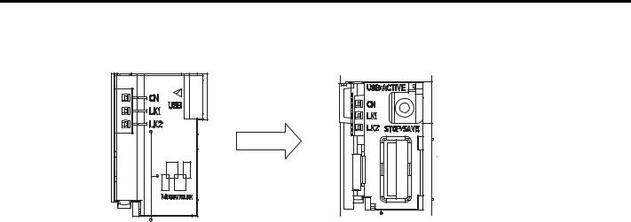
MECHATROLINK-III Connectors
Figure 5 illustrates connectors used to connect MECHATROLINK-III communications devices.
Figure 5 MECHATROLINK-III Connectors
Ethernet Connectors
Figure 6 illustrates the connector used to connect Ethernet communications devices.
Figure 6 Ethernet Connector
YASKAWA America, Inc. MP3300iec Hardware Manual YAI-SIA-IEC-7 |
11 |
5 CPU Specifications
USB Connector
Figure 5 illustrates the connector used to connect a USB memory device.
 USB connector
Open the cover.
Figure 7 USB Connector
NOTICE: Equipment Hazard. Before removing the USB memory device, press the STOP/SAVE switch and wait until the USB status indicator goes out. If the USB memory device is removed while the USB status indicator is lit or flashing, the data may become corrupted.
12 |
YASKAWA America, Inc. MP3300iec Hardware Manual YAI-SIA-IEC-7 |

6 Installation and Usage Conditions
6 Installation and Usage Conditions
This section describes installation and usage conditions for the MP3300iec Series Machine Controllers. Install the MP3300iec Series Controllers in an environment with the following conditions.
Installation and Usage Conditions
Table 1 MP3300iec Installation and Usage Conditions
|
Item |
Specification |
|
|
Ambient Operating |
0 to 60°C (Forced cooling is required if 55°C is exceeded.) |
|
|
Temperature |
||
|
|
||
|
Ambient Storage Temperature |
-25 to 85°C |
|
Environmental |
Ambient Operating Humidity |
10% to 95% RH (with no condensation) |
|
Conditions |
Ambient Storage Humidity |
10% to 95% RH (with no condensation) |
|
|
Pollution Level |
Conforms to JIS B 3502 Pollution Degree 2. |
|
|
Corrosive Gas |
There must be no combustible or corrosive gas. |
|
|
Operating Altitude |
2,000 m max. |
|
|
|
Conforms to JIS B 3502. |
|
|
|
Continuous vibration: 5 to 9 Hz with single-amplitude of 1.75 mm |
|
|
Vibration Resistance |
9 to 150 Hz with fixed acceleration of 4.9 m/s2 |
|
Mechanical |
Intermittent vibration: 5 to 9 Hz with single-amplitude of 3.5 mm |
||
|
|||
Operating |
|
9 to 150 Hz with fixed acceleration of 9.8 m/s2 |
|
Conditions |
|
10 sweeps each in X, Y, and Z directions for both intermittent and continuous vibration |
|
|
Shock Resistance |
Size of shock: Peak acceleration of 147 m/s2 (15 G) |
|
|
Duration: 11 ms |
||
|
|
3 times each in X, Y, and Z directions |
|
|
|
Conforms to EN 61000-6-2, EN 61000-6-4, and EN 55011 (Group 1 Class A). |
|
Electrical |
|
Power supply noise (FT noise): ±2 kV min. for one minute |
|
Operating |
Noise Resistance |
Radiation noise (FT noise): ±1 kV min. for one minute |
|
Conditions |
|
Ground noise (impulse noise): ±1 kV min. for 10 minutes |
|
|
|
Electrostatic noise (contact discharge method): ±6 kV or more, 10 times |
|
Installation |
Ground |
Ground to 100 Ω max. |
|
Conditions |
Cooling Method |
Natural cooling or forced-air cooling. Refer to Control Panel Cooling Method on page 14 |
YASKAWA America, Inc. MP3300iec Hardware Manual YAI-SIA-IEC-7 |
13 |
6Installation and Usage Conditions
Control Panel Cooling Method
The components that are used in the Machine Controller require the ambient operating temperature to be between 0 and 60 °C. Use one of the methods described below to ensure adequate cooling in the control panel.
NOTICE: Equipment Damage. Use forced-air cooling if the ambient temperature exceeds 55°C.
Control Panels with Natural Cooling
•Do not mount the Machine Controller at the top of the control panel, where the hot air that is generated inside the panel collects.
•Leave sufficient space above and below the Machine Controller, and maintain adequate distances from other devices, cable ducts, and other objects to ensure suitable air circulation.
•Do not mount the Machine Controller in any direction other than the specified direction.
•Do not mount the Machine Controller on top of any device that generates a significant amount of heat.
•Do not subject the Machine Controller to direct sunlight.
Control Panels with Forced-air Cooling
Install a fan near the center of and at the top or bottom of the Machine Controller for either of the following methods.
•Forced draft method (A fan or a similar device is used to circulate the air in the interior and the exterior of the panel.).
•Forced circulation method (A fan or a similar device is mounted to the airtight panel to circulate the air inside.).
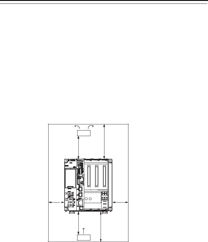
Note: 1. Use the following guideline when selecting the fan:
•80 x 80 mm min., Maximum air flow: 0.9 m3/min, Maximum static pressure: 26.5 Pa or higher.
2.Adjust the fan installation location and the direction of air flow as shown in Figure 8.
|
Fan |
Direction |
|
of air flow |
|
|
|
40 mm min. |
Approx. |
|
|
40 mm |
|
|
10 mm |
|
10 mm |
min.* |
|
min.* |
Approx. |
|
40 mm min. |
40 mm |
|
|
|
Direction |
|
|
of air flow |
|
|
Fan |
|
* For a control panel with natural cooling with the MBU-303 Base Unit: 30 mm min.
Figure 8 Fan installation location and air flow direction
14 |
YASKAWA America, Inc. MP3300iec Hardware Manual YAI-SIA-IEC-7 |

7 Base Unit Specifications
7 Base Unit Specifications
The specifications of the Base Units are listed in Table 2.
Table 2 Base Unit Specifications
Item |
|
Specification |
|
|||
1 slot |
3 slots |
8 slots DC |
8 slots AC |
|||
|
|
|||||
Model |
JEPMC-BU3304-E |
JEPMC-BU3303-E |
JEPMC-BU3302-E |
JEPMC-BU3301-E |
||
Abbreviation |
MBU-304 |
MBU-303 |
MBU-302 |
MBU-301 |
||
Number of Slots |
1 |
3 |
8 |
|
||
|
|
|
|
|
||
Mountable Modules |
MP2000-series Optional Modules |
|
|
|||
|
|
|
|
|
|
|
|
Input Voltage |
24 VDC |
|
|
110/220 VAC |
|
|
|
|
|
|
|
|
|
Allowable Input |
19.2 to 28.8 VDC |
|
|
85 to 132 VAC/ 198 to |
|
|
Voltage Range |
|
|
276 VAC |
||
|
|
|
|
|||
|
Input Current |
1.0 A max. (at rated |
1.5 A max. (at rated input/output) |
3.0 A max. (at rated |
||
|
input/output) |
input/output) |
||||
|
|
|
|
|||
|
Inrush Current |
40 A, 10 ms max. |
|
30 A, 10 ms max. |
40 A, 10 ms max. |
|
|
|
|
|
|
|
|
|
Allowable Power Loss |
1 ms |
|
|
20 ms |
|
Power Supply Section |
Time |
|
|
|
|
|
|
Rated Voltage |
5.15 V |
|
5.0 V |
|
|
|
|
|
|
|
|
|
|
Rated Current |
2.5 A |
4.5 A |
4.0 A |
8.0 A |
|
|
|
|
|
|
|
|
|
Output Current Range |
0 to 2.5 A |
0 to 4.5 A |
0.0 to 4.0 A |
0.0 to 8.0 A |
|
|
|
|
|
|
|
|
|
Rated Voltage |
5.15 V ±2% max. (5.05 to 5.25 V) |
|
|
||
|
Accuracy |
|
|
|||
|
|
|
|
|
||
|
Battery |
You can mount a memory backup Battery for retained variables, absolute encoder offsets, and |
||||
|
alarm history. |
|
|
|
||
|
|
|
|
|
||
|
|
A normally open relay output that is linked to the CPU Module status |
|
|||
|
|
Normal operation: Circuit closed. |
|
|
||
RLY OUT |
Error: Circuit open. |
|
|
|
||
Contact Ratings: |
|
|
|
|||
|
|
|
|
|
||
|
|
• 125 Vac, 0.4 A resistive load, 0.20 A inductive load |
|
|||
|
|
• 24 Vdc, 0.5 A resistive load, 0.25 A inductive load |
|
|||
Indicators |
POWER |
|
|
|
||
|
|
|
|
|
||
Connectors |
POWER: Power supply connector |
|
|
|||
RLY OUT: Relay contact connector |
|
|
||||
|
|
|
|
|||
YASKAWA America, Inc. MP3300iec Hardware Manual YAI-SIA-IEC-7 |
15 |
8 Switches
8 Switches
The CPU Module has the following two types of switches.
•DIP switches: Mode switches
•STOP/SAVE switch
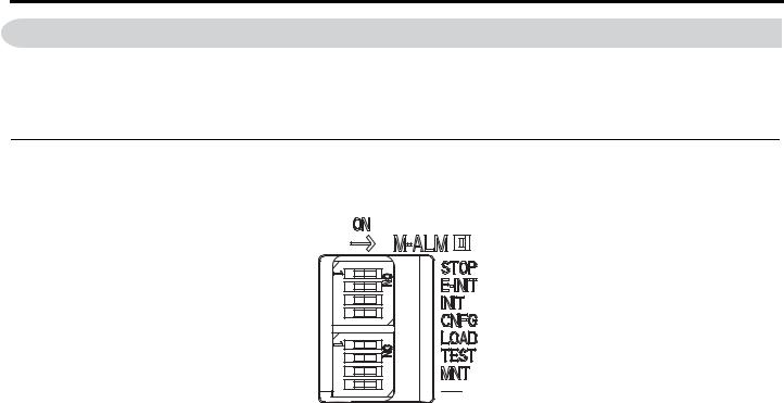
DIP Switches: Mode Switches
The SW1 and SW2 switches are checked at start-up, and their behavior is described in the following tables:
|
Table 3 SW1 Switches |
|
|
SW |
Description |
STOP |
When ON, prevents PLC from running. |
E-INIT |
When ON, overrides Ethernet configuration according to Table 5. |
INIT |
When ON, the controller uses the fixed, default configuration |
CNFG |
When ON, the controller creates Axes and I/O for all connected devices. (Auto-configuration) |
|
Table 4 SW2 Switches |
|
|
|
|
SW |
Description |
|
LOAD |
When ON, load either the user project or firmware from the USB thumb drive. See Table 6 for details. |
|
TEST |
When ON, the IP address is scrolled across the seven segment display. |
|
MNT |
When ON, controller starts up in supervisor mode. In this mode MECHATROLINK III, PLC, Modbus/TCP and Ethernet/IP |
|
do not start. The controller firmware can be updated, and clearing DOS FS alarms will repair the DOS FS. |
||
|
||
-- / DHCP |
DHCP Selection when E-INIT is ON. |
E-INIT and - switches can override the Ethernet configuration according to Table 5.
Table 5 Operation of E-INIT, E-PM0 and E-PM1 for Configuring Ethernet
|
E-INIT |
-- / DHCP |
Static Configuration |
OFF |
N/A |
192.168.1.1 |
ON |
OFF |
DHCP |
ON |
ON |
On start-up, the controller will automatically load firmware or user projects based on the LOAD and MNT switches. The USB thumb drive is available in any other circumstances.
Table 6 Operation of LOAD and MNT for USB Thumb Drive
|
E-INIT |
-- / DHCP |
|
Load user project from USB thumb drive |
ON |
OFF |
|
Install firmware and user project from USB |
ON |
ON |
|
thumb drive |
|||
|
|
16 |
YASKAWA America, Inc. MP3300iec Hardware Manual YAI-SIA-IEC-7 |
9 Display and Indicators
9 Display and Indicators
The CPU Module has the following display and four types of indicators.
•Display
•Status indicators
•USB status indicator
•MECHATROLINK-III status indicators
•Ethernet status indicators
Display
The following situations use the seven segment display:
•Manufacturing: During programming the seven segment display outputs “FLASH...”. When finished, the seven segment display outputs “donE”.
•Startup: If the controller cannot boot because of a bad firmware image check sum, the seven segment display outputs “bOOt ERROR”
•IP Address: If the TEST switch is ON, then the seven segment display outputs the IP address.
•Firmware update: During programming the seven segment display outputs “FLASH...”. When finished, the seven segment display outputs “donE”.
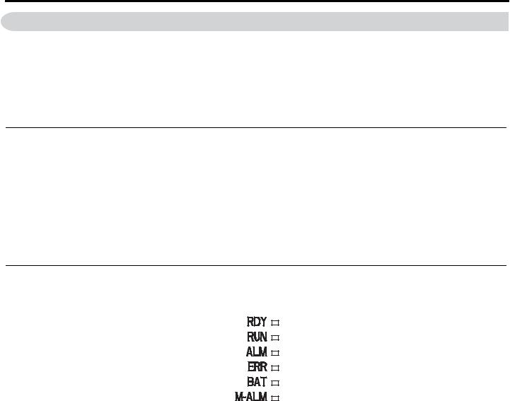
Status Indicators
These indicators show the status of the CPU Module.
|
Table 7 Status LED |
|
|
|
|
LED |
Description |
|
RDY |
ON when the controller has detected valid firmware and has started. |
|
RUN |
ON when PLC is running. |
|
ALM |
ON when an alarm is active. |
|
ERR |
ON at initial power up while firmware is loading. Turns off if firmware is valid. |
|
ON when a critical error occurs requiring a power cycle to recover. |
||
|
||
BAT |
ON when the battery needs replacing. |
|
M-ALM |
ON when JL100 (Mechatrolink Master) chip initialization fails. |
YASKAWA America, Inc. MP3300iec Hardware Manual YAI-SIA-IEC-7 |
17 |
9Display and Indicators
USB Status Indicator
This indicator shows the status of the USB memory.
Indicator Name |
|
Indicator Status |
Status |
Description |
||||||
|
|
|
|
|
Not lit |
No USB memory device |
No USB memory device has been inserted yet, or the |
|||
|
|
|
|
|
||||||
|
|
|
|
|
USB memory device is ready to be removed. |
|||||
|
|
|
|
|
|
|
|
|
|
|
USB |
|
|
|
|
|
|
|
|
|
|
|
|
|
|
Lit |
USB memory device inserted |
A USB memory device is inserted. |
||||
|
|
|
|
|||||||
ACTIVE |
|
|
|
|
||||||
|
|
|
|
|
|
|
|
|
|
|
|
|
|
|
|
|
|
|
Flashing |
Accessing USB memory |
The USB memory is being accessed. |
|
|
|
|
|
|
|||||
|
|
|
|
|
|
|
|
|
|
|
|
|
|
|
|
|
|
|
|
|
|
MECHATROLINK-III Status Indicators
These indicators show the status of the MECHATROLINK-III communications.
Indicator Name |
Color |
Status When Lit |
|||||||||||||
|
|
|
|
|
|
|
|
|
|
|
|
|
CN |
Green |
MECHATROLINK-III communications is established with the CPU Module as a slave (i.e., |
|
|
|
|
|
|
|
|
|
|
|
|
|
the Connect command is ON). |
||
|
|
|
|
|
|
|
|
|
|
|
|
|
|
|
|
|
|
|
|
|
|
|
|
|
|
|
|
|
|
|
|
|
|
|
|
|
|
|
|
|
|
|
|
|
LK1 |
Green |
MECHATROLINK-III communications are active on PORT1. |
|
|
|
|
|
|
|
|
|
|
|
|
|
|||
|
|
|
|
|
|
|
|
|
|
|
|
|
LK2 |
Green |
MECHATROLINK-III communications are active on PORT2. |
|
|
|
|
|
|
|
|
|
|
|
|
|
|||
|
|
|
|
|
|
|
|
|
|
|
|
|
|||
|
|
|
|
|
|
|
|
|
|
|
|
|
|
|
|
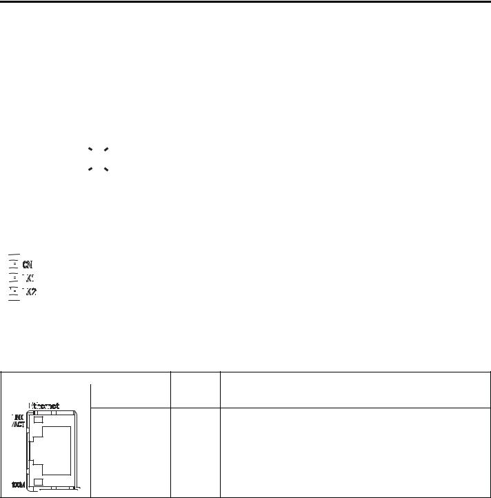
Ethernet Status Indicators
These indicators show the status of Ethernet communications.
|
|
|
|
|
|
|
|
|
|
|
|
|
|
|
|
Indicator Name |
Color |
Status When Not Lit, Lit, or Flashing |
|
|
|
|
|
|
|
|
|
|
|
|
|
|
|
|
|
|
LINK/ACT |
Yellow |
Lit: Ethernet link established. |
|
|
|
|
|
|
|
|
|
|
|
|
|
|
|
|
|
Flashing: Ethernet communications activity. |
||
|
|
|
|
|
|
|
|
|
|
|
|
|
|
|
|
|
|
|
|
|
|
|
|
|
|
|
|
|
|
|
|
|
|
|
|
|
|
|
|
100M |
Green |
Not lit: 10 M connection |
|
Lit: 100 M connection. We do not support GB connections. |
|||
|
|
18 |
YASKAWA America, Inc. MP3300iec Hardware Manual YAI-SIA-IEC-7 |

10 Self-Configuration
10 Self-Configuration
DIP Switch
Self-Configuration after Adding Devices such as Servopacks
The controller can automatically configure all the Mechatrolink devices. First, connect and power up all the Mechatrolink nodes (making sure they all have unique station numbers). Then, set the CNFG switch to the ON position and power up the controller. Wait for the RDY LED to come on and the controller will now have the new auto configuration.
Note: Controllers with an existing saved configuration cannot be auto configured until the currect configuration is deleted.
MotionWorks IEC
The MotionWorks IEC (Express or Pro) configuration can detect the configuration and provide the user with configuration choices. If a StartUp Configuration was already saved on the controller, the self-configure function will not allow new devices to be discovered. In this case, add them offline manually first.
YASKAWA America, Inc. MP3300iec Hardware Manual YAI-SIA-IEC-7 |
19 |

11 MECHATROLINK-III Specifications
11 MECHATROLINK-III Specifications
The specifications of the MECHATROLINK-III Network Master that is built into the CPU Unit are given in the following table.
|
Item |
|
Specification |
Remarks |
|
Communications ASIC |
JL-100 |
- |
|
|
Number of Communications Lines |
1 |
- |
|
|
Number of Communications Ports |
2 |
- |
|
|
(Connectors) |
|||
|
|
|
||
|
|
Communications Method |
M-III |
- |
|
|
Baud Rate |
100 Mbps |
- |
|
|
|
250 μs/0.5 ms/ |
|
MECHATROLINK |
|
Communications Cycle |
1 ms/1.5 ms/2 ms/2.5 ms/3 ms/ |
- |
|
|
3.5 ms/4 ms |
|
|
communications |
|
|
|
|
|
Number of Connected |
|
|
|
settings |
|
62 stations |
- |
|
|
Stations |
|||
|
Master |
|
|
|
|
Message Relaying |
Not Supported. |
- |
|
|
|
|||
|
|
C2 Messages |
Not Supported. |
- |
|
|
Retries |
Supported. |
0 to 4 retries |
|
|
Asynchronous Setting of |
|
|
|
|
High-speed Scan Cycle |
Not supported. |
An alarm will occur if setting is attempted. |
|
|
and Communications |
||
|
|
|
|
|
|
|
Cycle |
|
|
|
|
|
|
|
CPU Unit Specifications |
|
|
||
|
Item |
Specification |
|
Calendar |
|
|
Battery backup accurate to 1 minute of error per month. |
Ethernet |
|
|
10BASE-T, 100BASE-TX |
|
|
Auto-Negotiation / Baseline Wander Correction / Auto-MDIX |
|
|
|
|
|
M-III |
|
|
1981386-1 ×2 (TycoAMP) |
USB |
|
Connector |
DUSB-ARA42-T11A-FA (DDK), type A connector |
|
Function |
USB 2.0 host, 3 speeds (HS/FS/LS), 1 port |
|
|
|
||
Protection |
|
|
Hardware watchdog timer (PLD): 0 to 510 ms (register setting) |
Relay Output |
|
|
Contacts normally open for RUN status (RDY indicator lit), and OFF for WDT error status. The relay |
|
|
is built into the Power Supply Unit. |
|
|
|
|
|
Backup Circuit |
|
|
Battery: BR-1/2AA (Panasonic), 3.0 V |
20 |
YASKAWA America, Inc. MP3300iec Hardware Manual YAI-SIA-IEC-7 |
12 MECHATROLINK-III Network Topologies
12 MECHATROLINK-III Network Topologies
You can connect the MP3300iec Series Controller and drives or I/O with cascaded connections, star connections, or mixed cascaded/star network topologies. The following figures show examples of these types of network topologies.
Cascaded Connection
Cascaded connections allow you to connect one or more series of slave stations from the CPU Unit MECHATROLINKIII ports. Regardless of whether a single MECHATROLINK-III port is used, as shown in Figure 9, or two CPU Unit MECHATROLINK-III ports are used, as shown in Figure 10, these are called cascaded connections.
CPU Unit
No terminating resistor is required.
Up to 32 stations, including Servos and I/O
Figure 9 Cascaded Connections Using Only One Port
CPU Unit
No terminating


 resistor is required. No terminating


resistor is required.
Up to 32 Servo stations
Up to 62 stations, including I/O
Figure 10 Cascaded Connections Using Two Ports
Note: 1. Do not connect more than 32 stations up to the final slave station to any one CPU Unit port.
2. The maximum number of stations that you can connect with cascaded connections depends on the communications cycle.
YASKAWA America, Inc. MP3300iec Hardware Manual YAI-SIA-IEC-7 |
21 |

12MECHATROLINK-III Network Topologies
Star Connections
Star connections allow you to connect slave stations through Hub Modules. Each port on a Hub Module connects to only one slave station. You can also connect one additional Hub Module to the first Hub Module.
CPU Unit
Hub Module |
Hub Module |
Note: 1. Terminating resistors are not required.
2. The maximum number of stations that you can connect with star connections depends on the communications cycle.
22 |
YASKAWA America, Inc. MP3300iec Hardware Manual YAI-SIA-IEC-7 |
12 MECHATROLINK-III Network Topologies
Mixed Cascaded/Star Connections
You can combine both cascaded and star network topologies.
CPU Unit
Hub Module
No terminating resistor is required.
No terminating resistor is required.
Note: 1. Do not connect more than 32 stations to a single CPU Unit port, including the Hub Modules.
2. The maximum number of stations that you can connect with a mixed cascaded/star connections depends on the communications cycle.
YASKAWA America, Inc. MP3300iec Hardware Manual YAI-SIA-IEC-7 |
23 |

13 MECHATROLINK-III Synchronization between Modules
13 MECHATROLINK-III Synchronization between Modules
Timing at Which Modules Are Synchronized
Modules are automatically synchronized when the power supply is cycled.
If you perform any of the following operations after turning ON the power supply, save the settings to flash memory and then cycle the power supply again.
•When operation changes from asynchronized to synchronized as a result of changing the communications cycle
•When operation changes from synchronized to asynchronized or from asynchronized to synchronized as a result of changing the high-speed scan setting
•When the minimum response time in the MPiec controller is changed.
Changing Synchronization Cycles
When the scan cycle is changed, MECHATROLINK communications with all slave stations connected to the SVC32 are reset. Operation automatically changes to synchronized when communications are restored.
MECHATROLINK communications continue for all other Modules.
NOTICE
1.When you change the MECHATROLINK cycle, do so either with the CPU Function Module stopped or when motion commands are not being executed. Otherwise, application operations may be affected.
2.When changing the MECHATROLINK setting, the following operation will occur because MECHATROLINK communications are reset.
•Position information and zero point return completion information for Servo axes will be lost.
Changing the MECHATROLINK Communications Cycle
Operation is automatically synchronized as long as the high-speed scan setting is an integral multiple of the communications cycle.
It is not necessary to cycle the power supply.
NOTICE
If asynchronous operation is set as a result of changing the communications cycle, an alarm will occur for the Servo axis and an I/O error will occur for the I/O station. If this happens, change the setting back to synchronized, save the settings to flash memory, and then cycle the power supply.
24 |
YASKAWA America, Inc. MP3300iec Hardware Manual YAI-SIA-IEC-7 |

14 Devices Connectable via MECHATROLINK-III
14 Devices Connectable via MECHATROLINK-III
Servopacks
The following table shows Servopacks that are compatible with MECHATROLINK-III and can be connected to the controller.
Model |
|
Details |
SGDV-ƑƑƑƑ21 |
Σ-V Series AC Servo amplifiers for rotary motors |
|
SGDV-ƑƑƑE21 |
Σ-V Series Mini AC Servo amplifiers for rotary motors |
|
SGDV-ƑƑƑH21A |
Σ-V Series 200 VAC Large Capacity AC Servo amplifiers for rotary motors |
|
SGDV-ƑƑƑJ21A |
Σ-V Series 400 VAC Large Capacity AC Servo amplifiers for rotary motors |
|
SGDV-ƑƑƑƑ25 |
Σ-V Series AC Servo amplifiers for linear motors |
|
SGD7S-ƑƑƑA20A |
Σ-7 Series 200 |
VAC Large Capacity AC Servo amplifiers |
SGD7W-ƑƑƑA20A |
Σ-7 Series 200 |
VAC Large Capacity dual motor AC Servo amplifiers |
I/O Modules
The following table shows the module that is compatible with MECHATROLINK-III and can be connected to the controller.
Model |
Details |
|
JEPMC-MTD2310-E |
64-point I/O Module |
|
24VDC, 64 inputs, 64 outputs |
||
|
YASKAWA America, Inc. MP3300iec Hardware Manual YAI-SIA-IEC-7 |
25 |
 Loading...