


MP2000iec
Quick Reference Guide
MPiec Series Controllers
• Set up the MP2300Siec and MP2310iec controller (Firmware 2.x)
• Set up the MP2600Siec controller (Firmware 2.x)
• Set the Front Panel Switches
• Set IP Address of PC (Windows 7)
• Establish Ethernet Communication between Controller and PC
• Download project to controller
• Login to Webserver
• Set IP Address of Controller
• Update firmware
• Save Project Archive (Backup controller and servo parameters)
• Load Project Archive
• Startup from Project Archive
• Clear Alarm A.810 (Initialize Absolute Encoders)
• Clear Alarm A.CC0
• Replace the controller
• Replace a Servopack (Mechatrolink)
• Replace ServoMotor
• Replace Battery
• Machine Operations and JAVA version
• Start MotionWorks IEC
• Open a saved project
• Open a zipped project
• Start a new project
• Save and Backup Project
• Set Project IP Address (Connect project to controller)
• Reset the MPiec controller back to factory settings
• Reset connected Servos to factory settings
• Clear Alarm A.810 (Initialize Absolute Encoders)
• Extract/Open the project stored in the controller
Modbus/TCP and Ethernet/IP
User Libraries
OPC Server
Logic Analyzer
Contents
Web Sever Procedures
MotionWorks IEC Procedures
Print Date: 1/23/2015
MP2000iec Series QRG Rev 3.3
Web Sever Procedures
MP2000iec Series Controllers
1.0 Set up the MP2300Siec and MP2310iec controller (Firmware 2.x)
KEY INFORMATION
The controller will be comissioned for a new project.
Scenario 1: Controller new in box
Scenario 2: Controller with unknown configuration
Step Description Detail
1 Install option modules
Use the battery cover to remove the module cover and module, if required, as
illustrated in manual YEA-SIA-IEC-2 section 5.1.5.
2 Verify DIP switch setting
SW1 = all off except CNFG on. SW2 = all off. See table 1.03 below for more
details.
3 Wire 24V DC Power Wire and install according to the hardware manual YEA-SIA-IEC-2
4
Establish ethernet
communication with controller
See procedure 1.4 - type controller IP address into Internet Explorer
5 Login to Webserver Login as Admin/MP2300S (case sensitive) See procedure 2.1.
6 Set IP address
Select "Ethernet Config". Enter IP address and Subnet Mask. Click "Update Built-in
Ethernet Settings".
7 Set default gateway
Select "Ethernet Config". Enter Default Gateway. If not gateway device exists on
the network, enter the same address as the IP address. Click "Update Built-in
Ethernet Settings".
8 Set date and time
Select "Set Clock". Adjust the date and time. Check box "auto-run". Click "Set
Date/Time" to apply.
9 Reboot Controller
Under "Maintenance" -> reboot, then "Reboot Controller" and "OK" to confirm. Wait
45 seconds for reboot.
10 Upgrade firmware
The latest firmware should be loaded before application development. For field
replacement the firmware may be matched to the original firmware level. (See
procedure 2.5)
1.1 Set up the MP2600Siec controller (Firmware 2.x)
KEY INFORMATION
The controller will be comissioned for a new project.
Scenario 1: Controller new in box
Scenario 2: Controller with unknown configuration
Step Description Detail
1 Install Battery for SRAM
Refer to Manual YEA-SIA-IEC-6 section 7. Remove case, insert metal bracket,
secure battery holder with screw. Connect battery extension, slide battery in holder.
Replace case, connect the battery.
2 Verify DIP switch setting
SW1 = all off except CNFG on. SW2 = all off. See table 1.03 below for more
details.
3 Wire and Install Servo
Wire and install according to the corresponding Sigma-5 Option Manual such as
SIEPS80000060, SIEPS80000066, SIEPS80000089, SIEPS80000098
4
Establish ethernet
communication with controller
See procedure 1.4 - type controller IP address into Internet Explorer to open the
controller's built in webserver.
5 Login to Webserver
Login as Admin/MP2600 (case sensitive)
6 Set IP address
Select "Ethernet Config". Enter IP address and Subnet Mask. Click "Update Built-in
Ethernet Settings".
7 Set default gateway
Select "Ethernet Config". Enter Default Gateway. If no gateway device exists on
the network, enter the same address as the IP address. Click "Update Built-in
Ethernet Settings".
8 Set date and time
Select "Set Clock". Adjust the date and time. Check box "auto-run". Click "Set
Date/Time" to apply.
9 Initialize SRAM Initialize SRAM -> Re-initialize SRAM, OK
10 Reboot Controller
Under "Maintenance" -> reboot, then "Reboot Controller" and "OK" to confirm. Wait
45 seconds for reboot.
11 Upgrade firmware
The latest firmware should be loaded before application development. For field
replacement upgrade to the original firmware level. (See procedure 2.5)
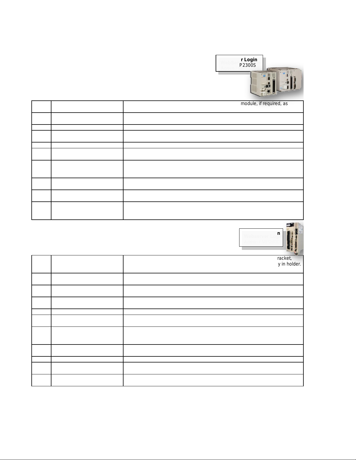
Webserver Login
Admin / MP2600
WebServer Login
Admin / MP2300S
Page 2 of 15

MP2000iec Series QRG Rev 3.3
1.2 Set the Front Panel Switches
KEY INFORMATION CNFG normally ON, all others OFF
Switches only have an effect during power-on
Switches listed for MP2000iec products. Refer to manual for MP3000iec series.
Switch Normal Setting Detail
STOP OFF
Immediately stops the program from executing. Required for test run from Hardware
Configuration or Web Interface
SUP OFF
Boots the controller in "Supervisor mode" before a firmware update. Supervisor
mode can also be activated through the web interface
INIT OFF
Initializes SRAM contents, including retained variable data, clock, and absolute
encoder offsets. Useful when SRAM has been corrupted when lithium battery has
been disconnected for a long time.
Controller uses "default" hardware configuration. Useful to recover if invalid
"startup" configuration has been saved to controller.
CNFG ON
Discovers option modules and Mechatrolink devices at power-up. May remain on.
The discovered "disco" configuration is not used when the saved "startup"
configuration exists. The discovered configuration may be saved using
MotionWorks IEC Hardware Configuration.
MON OFF For "network boot" or "ROM boot". Leave OFF
TEST OFF For "system use" or "normal operation". Leave OFF
E-INIT OFF
Temporarily override the IP addresss with 192.168.1.1. Configured IP address is not
affected. MP2600iec Port B is set to 192.168.2.1
E-TEST OFF Self Diagnosis of Ethernet. Leave OFF>
1.3 Set IP Address of PC (Windows 7)
KEY INFORMATION
Step Description Detail
1 Open Network Connections
In windows 7, go to control panel, network and internet, network and sharing center,
and on the left choose change adapter settings. Alternative: Type "ncpa.cpl" in
windows search.
2
Open Properties of the
Connection
Find the connection you're using, such as Local Area Connection and right-click to
choose properties
3
Enter static IP address in
TCP/IPv4 properties.
Find "Internet Protocol Version 4 (TCP/IPv4)", then properties. Change to "use the
following IP address" and type in an IP address on the same subnet as the
controller. Example: If the MPiec controller is 192.168.1.1 by default, then the PC
can be for example 192.168.1.50 . The subnet mask will autofill with 255,255,255,0.
Click ok for the setting to take effect.
4 Troubleshoot
Under the start button, type c-m-d. Type ipconfig. IP address information about
your PC appears.
1.4 Establish Ethernet Communication between Controller and PC
KEY INFORMATION
MP2000iec IP address = 192.168.1.1 when powered up with E-INIT dipswitch ON
This switch setting does not affect the controller program or the configured address
The IP address will revert to the configured address when the E-INIT dipswitch is
OFF at power-up
Step Description Detail
1
Determine and set IP address of
PC
See procedure above for PC. Set IP address with required subnet, often the subnet
is 1
2
Connect Ethernet Cables and
apply power
If possible, simplify the ethernet connection by disconnecting the controller from any
network, and connect directly to the PC.
3
Determine IP address of
Controller
Method 1: MotionWorks IEC project -> project tree, physical hardware, right click
resource, and choose settings.
Method 2: MotionWorks IEC hardware configuration, TCP/IP settings
Method 3: Reboot controller with E-INIT switch ON to set 192.168.1.1 (MP2600iec
Port A is 192.168.1.1 and Port B is 192.168.2.1).
4 Open Webserver
Microsoft Internet Explorer, address bar, type the IP address of controller. Default is
192.168.1.1
5 Troubleshoot
Ping Test. Under the start button, type c-m-d. Type ping followed by the ip address
of the controller. For example, 192.168.1.1. Ping test determines if there is any
level of communication between PC and controller.
Page 3 of 15

MP2000iec Series QRG Rev 3.3
1.5 Login to Webserver
KEY INFORMATION
Step Description Detail
1
Establish ethernet
communication with controller
See procedure 1.4 - type controller IP address into Internet Explorer to open the
controller's built in webserver.
2 Enter Login Credentials
Login: Admin (case sensitive).
Password: MP2300S (all caps, for MP2300Siec and MP2310iec).
Password: MP2600 (all caps, for MP2600iec).
Password: MP3200 (all caps, for MP3200iec)
Troubleshoot
The login configuration may have been customized. Obtain the login information
from the network administrator. Otherwise, the controller may be reset to factory
default using Motionworks IEC. See procedure __
1.6 Set IP Address of Controller
KEY INFORMATION
Step Description Detail
1 Login to Webserver See Procedure. Login: Admin. Password: MP2300S, MP2600, MP3200, MP3300
2 Open "Ethernet Config" On the left side
3 Set IP address
Select "Ethernet Config". Enter IP address and Subnet Mask. Click "Update Built-in
Ethernet Settings" to save.
4 Set default gateway
Select "Ethernet Config". Enter Default Gateway. If not gateway device exists on
the network, enter the same address as the IP address. Click "Update Built-in
Ethernet Settings" to save.
5 Turn off E-INIT switch
E-INIT must be off for configured ethernet settings to take effect at next reboot. If E-
INIT is left on, the address will be 192.168.1.1 regardless of the Ethernet Config
settings.
6 Reboot Controller
Under "Maintenance" -> reboot, then "Reboot Controller" and "OK" to confirm. Wait
45 seconds for reboot. The settings do not take effect until the controller is
rebooted with E-INIT off.
1.7 Update firmware
KEY INFORMATION
Do NOT update firmware in the field unless directed by Yaskawa.
DO update firmware before code development begins on new application.
Step Description Detail
1
Establish ethernet
communication with controller
See procedure 1.4 - type controller IP address into Internet Explorer to open the
controller's built in webserver.
2
Determine current firmware
version
The webserver welcome page lists the firmware version number, build number, and
build date
3 Acquire a firmware zip file yaskawa.com/iecfw to download firmware files. Must log in to yaskawa.com
4 Login to Webserver See Procedure. Login: Admin. Password: MP2300S, MP2600, MP3200, MP3300
5 Stop all motion Operate the machine according to existing program.
6 Enable supervisor mode
Under "Maintenance" -> "Update Firmware", then click "enabled via software" and
"reboot controller". Wait 45 seconds for reboot.
7 Load firmware zip file
Under "Maintenance" -> "Update Firmware", then browse for firmware file, and
"upload". Upload takes about 1 minute. Do not attempt to unzip the firmware file.
8 Update firmware
Confirm the update version. Then click "update" button. The update takes about 2
minutes. Do not use the controller during this time.
9 Reboot Controller
Under "Maintenance" -> reboot, then "Reboot Controller" and "OK" to confirm. Wait
45 seconds for reboot.
Page 4 of 15

MP2000iec Series QRG Rev 3.3
1.8 Save Project Archive (Backup controller and servo parameters)
KEY INFORMATION The project archive contains the critical data for the controller and servopacks.
Save this archive at time of machine comissioning and after any change is made.
Step Description Detail
1 Login to Webserver See Procedure. Login: Admin. Password: MP2300S, MP2600, MP3200, MP3300
2 Verifiy Drive Parameters
Drive Parameters -> User Parameters, "verify" each axis. Verify compares
parameters in the archive with the current parameters in the servo. IF Verify is
successful, proceed to next step. IF Verify is not successful, then the archive drive
parameters do not match the current parameters in the servos. Use MotionWorks
IEC hardware configuration to import parameters to project archive.
3 Save archive from controller
Project Archive -> "Browse" and select the project archive file. Then "Receive from
Controller". Navigate to directory on PC to save *.zip file.
1.9 Load Project Archive
KEY INFORMATION This procedure only sends the controller program and configuration.
Step Description Detail
1 Login to Webserver See Procedure. Login: Admin. Password: MP2300S, MP2600, MP3200, MP3300
2 Obtain the project archive file
*.zip is the file extention. The project archive must have been previously saved
from an existing controller. It can also be created by MotionWorks IEC.
3 Send archive to controller
Project Archive -> "Browse" and select the project archive file. Select "Clean Install"
to delete any previous archive files. Then "Send to Controller", "OK". Wait 1-2
minutes. When complete the button changes from "Wait" back to "Send to
Controller".
4 Reboot
Under "Maintenance" -> reboot, then "Reboot Controller" and "OK" to confirm. Wait
45 seconds for reboot.
1.A Startup from Project Archive
KEY INFORMATION
Project Archive contains all required data including servo parameters.
Archive is not active until reboot.
Step Description Detail
1 Set up the controller See procedure 1.0, for new controllers.
2 Stop all motion Operate the machine according to existing program.
3 Login to Webserver See Procedure. Login: Admin. Password: MP2300S, MP2600, MP3200, MP3300
4 Obtain the project archive file
*.zip is the file extention. The project archive must have been previously saved
from an existing controller. It can also be created by MotionWorks IEC.
5 Send archive to controller
Project Archive -> Browse, select the project archive file. "Clean Install" to delete
any previous archive files. Then "Send to Controller", "OK". Wait 1-2 minutes.
When complete the button changes from "Wait" back to "Send to Controller".
6 Send Drive Parameters
Drive Parameters -> User Parameters, "verify" each axis. Verify compares
parameters in the archive with the current parameters in the servo. "Write" and
"OK" to send parameters from archive to servo. Takes just a couple seconds to
write.
7 Reboot #1
Under "Maintenance" -> reboot, then "Reboot Controller" and "OK" to confirm. Wait
45 seconds for reboot.
8
Initialize Absolute Encoders to
clear A.810, A.820, A.CC0
Machine Operations. Determine which axis number has the alarm. Drive PN tab ->
pull down to select the axis number. Click "abs encoder init" then "Multiturn
Reset". Clears alarms A.810 and A.CC0.
9 Reboot #2
Under "Maintenance" -> reboot, then "Reboot Controller" and "OK" to confirm. Wait
45 seconds for reboot.
10
Zero-Set / Home and machine
calibration
Follow steps according to application programming of machine. Home offsets for
absolute encoder are stored in SRAM of controller.
Page 5 of 15
 Loading...