


 Loading...
Machine Controller MP2000 Series
263IF-01
EtherNet/IP Communication Module
USER'S MANUAL
Model: JAPMC-CM2304-E
263IF-01
MS
 NS
NS
 IP TX
IP TX 
 RX
RX
INIT
TEST
 NO
NO
OFF ON
EtherNet/IP
LINK
100M
EtherNet/IP Communication
263IF-01 Module
Mounting and Starting the Module
EtherNet/IP Transmission Definition
Explicit Message and Explicit Message Send Function
Troubleshooting
Appendices
1
2
3
4
5
6
App
MANUAL NO. SIEP C880700 39A

Copyright © 2008 YASKAWA ELECTRIC CORPORATION
All rights reserved. No part of this publication may be reproduced, stored in a retrieval system, or transmitted, in any form, or by any means, mechanical, electronic, photocopying, recording, or otherwise, without the prior written permission of Yaskawa. No patent liability is assumed with respect to the use of the information contained herein. Moreover, because Yaskawa is constantly striving to improve its high-quality products, the information contained in this manual is subject to change without notice. Every precaution has been taken in the preparation of this manual. Nevertheless, Yaskawa assumes no responsibility for errors or omissions. Neither is any liability assumed for damages resulting from the use of the information contained in this publication.

Using this Manual
This manual describes EtherNet/IP Communication Module 263IF-01 for the MP2000-series Machine Controller. Read this manual thoroughly before using the 263IF-01. Keep this manual in a safe place for future reference.
Basic Terms
Unless otherwise specified, the following definitions are used:
• MP2000-series Machine Controllers: MP2100M, MP2200, MP2300, MP2310, MP2300S, and MP2500MD Machine Controllers
•PLC: Programmable Logic Controller
•MPE720: The Programming Device Software or a personal computer running the Programming Device Software
Manual Configuration
This manual consists of the chapters listed in the following table. Read the chapters of this manual as required by the purpose.
|
|
Selecting |
Studying |
Designing |
Panel |
|
Maintenance |
|
|
Models and |
Trial |
||||
|
|
Specifications |
the |
Installation |
and |
||
|
|
Peripheral |
and Ratings |
System |
and Wiring |
Operation |
Inspection |
|
|
Devices |
|
||||
|
|
|
|
|
|
|
|
|
|
|
|
|
|
|
|
Chapter 1 |
EtherNet/IP |
9 |
|
9 |
|
|
|
|
Communication |
|
|
|
|
||
|
|
|
|
|
|
|
|
|
|
|
|
|
|
|
|
Chapter 2 |
263IF-01 Module |
9 |
9 |
9 |
9 |
9 |
9 |
|
|
|
|
|
|
|
|
Chapter 3 Mounting and Starting |
|
9 |
9 |
9 |
9 |
9 |
|
|
the Module |
|
|||||
|
|
|
|
|
|
|
|
|
|
|
|
|
|
|
|
Chapter 4 |
EtherNet/IP |
|
|
|
|
|
|
|
Transmission |
|
9 |
9 |
|
9 |
9 |
|
Definition |
|
|
|
|
|
|
|
|
|
|
|
|
|
|
Chapter 5 Explicit Message and |
|
|
|
|
|
|
|
|
Explicit Message |
|
|
9 |
|
9 |
|
|
Send Function |
|
|
|
|
|
|
|
|
|
|
|
|
|
|
Chapter 6 |
Troubleshooting |
|
9 |
9 |
9 |
9 |
9 |
|
|
|
|
|
|
|
|
Graphic Symbols Used in this Manual
The graphic symbols used in this manual indicate the following type of information.
This symbol is used to indicate important information that should be memorized or minor precautions, such as precautions that will result in alarms if not heeded.
Indication of Reverse Signals
In this manual, the names of reverse signals (ones that are valid when low) are written with a forward slash (/) before the signal name, as shown in the following example:
<Notation Examples> |
S-ON |
= /S-ON |
|
|
|
||
|
P-CON |
= /P-CON |
|
iii

Related Manuals
The following table lists the manuals relating to the 263IF-01 Module for the MP2000-series Machine Controller. Refer to these manuals as needed.
Manual Name |
|
Manual Number |
Contents |
|
Machine Controller MP2100/MP2100M |
|
|
Describes how to use the MP2100 and MP2100M |
|
User's Manual |
|
SIEPC88070001 |
||
|
Machine Controllers. |
|||
Design and Maintenance |
|
|
||
|
|
|
||
|
|
|
|
|
Machine Controller MP2200 |
|
SIEPC88070014 |
Describes how to use the MP2200 Machine Con- |
|
User's Manual |
|
troller and the modules that can be connected. |
||
|
|
|||
|
|
|
|
|
Machine Controller MP2300 |
|
SIEPC88070003 |
Describes how to use the MP2300 Basic Module |
|
Basic Module User's Manual |
|
and the modules that can be connected. |
||
|
|
|||
|
|
|
|
|
Machine Controller MP2310 |
|
SIEPC88073201 |
Describes how to use the MP2310 Basic Module |
|
Basic Module User's Manual |
|
and the modules that can be connected. |
||
|
|
|||
|
|
|
|
|
Machine Controller MP2300S |
|
SIEPC88073200 |
Describes how to use the MP2300S Basic Module |
|
Basic Module User's Manual |
|
and the modules that can be connected. |
||
|
|
|||
|
|
|
|
|
Machine Controller |
|
|
Describes how to use the MP2500, MP2500M, |
|
MP2500/MP2500M/MP2500D/MP2500MD |
SIEPC88075200 |
|||
MP2500D, and MP2500MD Machine Controllers. |
||||
User's Manual |
|
|
||
|
|
|
||
|
|
|
|
|
Machine Controller MP2000 Series |
|
|
Provides a detailed description on the MP2000 |
|
Motion Module Built-in SVB/SVB-01 |
|
SIEPC88070033 |
Series Machine Controller built-in SVB Module |
|
User's Manual |
|
|
and slot-mounting optional SVB-01 Module. |
|
|
|
|
|
|
Machine Controller MP2000 Series |
|
|
Provides the information on the Communication |
|
|
SIEPC88070004 |
Module that can be connected to MP2000 Series |
||
Communication Module User's Manual |
|
Machine Controller and the communication meth- |
||
|
|
|||
|
|
|
ods. |
|
|
|
|
|
|
Machine Controller MP2000 Series |
|
|
Provides a detailed description of the FL-net Com- |
|
262IF-01 FL-net Communication Module |
SIEPC88070036 |
munication Module 262IF-01 that can be connected |
||
User's Manual |
|
|
to an MP2000-series Machine Controller. |
|
|
|
|
|
|
Machine Controller MP900/MP2000 |
Series |
SIEZ-C887-1.2 |
Describes the instructions used in MP900/MP2000 |
|
User's Manual: Ladder Programming |
|
|
ladder programming. |
|
Machine Controller MP900/MP2000 |
Series |
SIEZ-C887-1.3 |
Describes the instructions used in MP900/MP2000 |
|
User's Manual: Motion Programming |
|
|
motion programming. |
|
Machine Controller MP2000 Series |
|
|
Describes how to install and operate the program- |
|
MPE720 Programming Device Version 6 |
SIEPC880700 30 |
ming tool MPE720 version 6 for MP2000 Series |
||
User's Manual |
|
|
Machine Controllers. |
|
|
|
|
|
|
Machine Controller MP900/MP2000 |
Series |
|
Describes how to install and operate the MP900/ |
|
MPE720 Software for Programming Device |
SIEPC88070005 |
|||
MP2000 Series programming system (MPE720). |
||||
User's Manual |
|
|
||
|
|
|
||
|
|
|
|
|
Machine Controller MP900/MP2000 |
Series |
SIEZ-C887-13.1 |
Describes the programming instructions of the New |
|
Ladder Editor, which assists MP900/MP2000 |
||||
New Ladder Editor Programming Manual |
|
Series design and maintenance. |
||
|
|
|
||
|
|
|
|
|
Machine Controller MP900/MP2000 |
Series |
SIEZ-C887-13.2 |
Describes the operating methods of the New Ladder |
|
Editor, which assists design and maintenance of the |
||||
New Ladder Editor User's Manual |
|
|
MP900/MP2000 series Machine Controllers. |
|
|
|
|
||
|
|
|
|
|
Machine Controller MP920 |
|
|
Describes the functions, specifications, and applica- |
|
User's Manual |
|
SIEZ-C887-2.6 |
tion methods of the MP920 Communication Mod- |
|
Communication Modules |
|
|
ules (217IF, 215IF, and 218IF). |
|
|
|
|
|
|
Copyrights
EtherNet/IP and DeviceNet are registered trademarks of the ODVA (Open DeviceNet Vendor Association Inc.).
Ethernet is a registered trademark of the Xerox Corporation.
Other product names and company names are the trademarks or registered trademarks of the respective company. “TM” and the → mark do not appear with product or company names in this manual.
iv

Safety Information
The following conventions are used to indicate precautions in this manual. Information marked as shown below is important for the safety of the user. Always read this information and heed the precautions that are provided. The conventions are as follows:

 WARNING

 CAUTION

 PROHIBITED

 MANDATORY
Indicates precautions that, if not heeded, could possibly result in loss of life or serious injury.
Indicates precautions that, if not heeded, could result in relatively serious or minor injury, or property damage.
If not heeded, even precautions classified under  CAUTION can lead to serious results depending on circumstances.
Indicates prohibited actions. Specific prohibitions are indicated inside  .
.
For example,  indicates no fire or open flame.
Indicates mandatory actions. Specific actions are indicated inside ● .
For example, |
indicates that grounding is required. |
Safety Precautions
The following precautions are for checking products on delivery, storage, transportation, installation, wiring, operation, application, inspection, and disposal. These precautions are important and must be observed.
General Precautions
 WARNING
Before starting operation while connected to the machine, ensure that an emergency stop procedure has been provided and is working correctly.
There is a risk of injury.
Do not touch anything inside the product.
There is a risk of electrical shock.
Always keep the front cover attached when power is being supplied.
There is a risk of electrical shock.
Observe all procedures and precautions given in this manual for trial operation.
Operating mistakes while the Servomotor and machine are connected can cause damage to the machine or even accidents resulting in injury or death.
Do not remove the front cover, cables, connector, or options while power is being supplied.
There is a risk of electrical shock.
Do not damage, pull on, apply excessive force to, place heavy objects on, or pinch cables.
There is a risk of electrical shock, operational failure of the product, or burning.
Do not attempt to modify the product in any way.
There is a risk of injury or device damage.
Do not approach the machine when there is a momentary interruption to the power supply. When power is restored, the MP2000-series Machine Controller or machine connected to it may start operation suddenly. Provide suitable safety measures to protect people when operation restarts.
There is a risk of injury.
Do not allow installation, disassembly, or repairs to be performed by anyone other than specified personnel.
There is a risk of electrical shock or injury.
v

Storage and Transportation
 CAUTION
Do not store or install the product in locations subject to the following. There is a risk of fire, electric shock, and machine product damage.
Direct sunlight
Ambient temperatures exceeding the storage or operating conditions
Ambient humidity exceeding the storage or operating conditions
Extreme changes in temperature that would result in condensation
Corrosive or flammable gas
Excessive dust, dirt, salt, or metallic powder
Water, oil, or chemicals
Vibration or shock
Do not overload the product during transportation.
There is a risk of injury or an accident.
Never subject the product to an atmosphere containing halogen (fluorine, chlorine, bromine, or iodine) during transportation or installation.
There is a risk of device damage or an accident.
If disinfectants or insecticides must be used to treat packing materials such as wooden frames, pallets, or plywood, the packing materials must be treated before the product is packaged, and methods other than fumigation must be used.
Example: Heat treatment, where materials are kiln-dried to a core temperature of 56°C for 30 minutes or more.
If the electronic products, which include stand-alone products and products installed in machines, are packed with fumigated wooden materials, the electrical components may be greatly damaged by the gases or fumes resulting from the fumigation process. In particular, disinfectants containing halogen, which includes chlorine, fluorine, bromine, or iodine can contribute to the erosion of the capacitors.
Installation
 CAUTION
Never use the product in locations subject to water, corrosive atmospheres, or flammable gas, or near burnable objects.
There is a risk of electrical shock or fire.
Do not step on the product or place heavy objects on the product.
There is a risk of injury.
Do not block the air exhaust port on the product. Do not allow foreign objects to enter the product.
There is a risk of element deterioration inside, an accident, or fire.
Always mount the product in the specified orientation.
There is a risk of an accident.
Do not subject the product to strong shock.
There is a risk of an accident.
vi

Wiring
 CAUTION
Check the wiring to be sure it has been performed correctly.
There is a risk of motor run-away, injury, or an accident.
Always use a power supply of the specified voltage.
There is a risk of burning.
In places with poor power supply conditions, take all steps necessary to ensure that the input power is supplied within the specified voltage range.
There is a risk of device damage.
Install breakers and other safety measures to provide protection against shorts in external wiring.
There is a risk of fire.
Provide sufficient shielding when using the product in the locations subject to the following.
There is a risk of device damage.
Noise, such as from static electricity
Strong electromagnetic or magnetic fields
Radiation
Near power lines
Selecting, Separating, and Laying External Cables
 CAUTION
Consider the following items when selecting the I/O signal lines (external cables) to connect the product to external devices.
Mechanical strength
Noise interference
Wiring distance
Signal voltage, etc.
Separate the I/O signal lines from the power lines both inside and outside the control box to reduce the influence of noise from the power lines.
If the I/O signal lines and power lines are not separated properly, malfunctioning may result.
Example of Separated External Cables
 Steel separator
Power circuit |
General |
|
control circuit |
Digital I/O |
|
cables |
cables |
signal cables |
Maintenance and Inspection Precautions
 CAUTION
Do not attempt to disassemble the product.
There is a risk of electrical shock or injury.
Do not change wiring while power is being supplied.
There is a risk of electrical shock or injury.
vii

Disposal Precautions
 CAUTION
Dispose of the product as general industrial waste.
General Precautions
Observe the following general precautions to ensure safe application.
The products shown in illustrations in this manual are sometimes shown without covers or protective guards. Always replace the cover or protective guard as specified first, and then operate the products in accordance with the manual.
The drawings presented in this manual are typical examples and may not match the product you received.
If the manual must be ordered due to loss or damage, inform your nearest Yaskawa representative or one of the offices listed on the back of this manual.
viii

Warranty
( 1 ) Details of Warranty
Warranty Period
The warranty period for a product that was purchased (hereinafter called “delivered product”) is one year from the time of delivery to the location specified by the customer or 18 months from the time of shipment from the Yaskawa factory, whichever is sooner.
Warranty Scope
Yaskawa shall replace or repair a defective product free of charge if a defect attributable to Yaskawa occurs during the warranty period above. This warranty does not cover defects caused by the delivered product reaching the end of its service life and replacement of parts that require replacement or that have a limited service life.
This warranty does not cover failures that result from any of the following causes.
1.Improper handling, abuse, or use in unsuitable conditions or in environments not described in product catalogs or manuals, or in any separately agreed-upon specifications
2.Causes not attributable to the delivered product itself
3.Modifications or repairs not performed by Yaskawa
4.Abuse of the delivered product in a manner in which it was not originally intended
5.Causes that were not foreseeable with the scientific and technological understanding at the time of shipment from Yaskawa
6.Events for which Yaskawa is not responsible, such as natural or human-made disasters
( 2 ) Limitations of Liability
1.Yaskawa shall in no event be responsible for any damage or loss of opportunity to the customer that arises due to failure of the delivered product.
2.Yaskawa shall not be responsible for any programs (including parameter settings) or the results of program execution of the programs provided by the user or by a third party for use with programmable Yaskawa products.
3.The information described in product catalogs or manuals is provided for the purpose of the customer purchasing the appropriate product for the intended application. The use thereof does not guarantee that there are no infringements of intellectual property rights or other proprietary rights of Yaskawa or third parties, nor does it construe a license.
4.Yaskawa shall not be responsible for any damage arising from infringements of intellectual property rights or other proprietary rights of third parties as a result of using the information described in catalogs or manuals.
ix

( 3 ) Suitability for Use
1.It is the customer’s responsibility to confirm conformity with any standards, codes, or regulations that apply if the Yaskawa product is used in combination with any other products.
2.The customer must confirm that the Yaskawa product is suitable for the systems, machines, and equipment used by the customer.
3.Consult with Yaskawa to determine whether use in the following applications is acceptable. If use in the application is acceptable, use the product with extra allowance in ratings and specifications, and provide safety measures to minimize hazards in the event of failure.
•Outdoor use, use involving potential chemical contamination or electrical interference, or use in conditions or environments not described in product catalogs or manuals
•Nuclear energy control systems, combustion systems, railroad systems, aviation systems, vehicle systems, medical equipment, amusement machines, and installations subject to separate industry or government regulations
•Systems, machines, and equipment that may present a risk to life or property
•Systems that require a high degree of reliability, such as systems that supply gas, water, or electricity, or systems that operate continuously 24 hours a day
•Other systems that require a similar high degree of safety
4.Never use the product for an application involving serious risk to life or property without first ensuring that the system is designed to secure the required level of safety with risk warnings and redundancy, and that the Yaskawa product is properly rated and installed.
5.The circuit examples and other application examples described in product catalogs and manuals are for reference. Check the functionality and safety of the actual devices and equipment to be used before using the product.
6.Read and understand all use prohibitions and precautions, and operate the Yaskawa product correctly to prevent accidental harm to third parties.
( 4 ) Specifications Change
The names, specifications, appearance, and accessories of products in product catalogs and manuals may be changed at any time based on improvements and other reasons. The next editions of the revised catalogs or manuals will be published with updated code numbers. Consult with your Yaskawa representative to confirm the actual specifications before purchasing a product.
x
Contents
Using this Manual - - - - - - - - - - - - - - - - - - - - - - - - - - - - - - - - - - - - - - - - - - - - - - - - - - - - - - - iii Safety Information - - - - - - - - - - - - - - - - - - - - - - - - - - - - - - - - - - - - - - - - - - - - - - - - - - - - - - - v Safety Precautions - - - - - - - - - - - - - - - - - - - - - - - - - - - - - - - - - - - - - - - - - - - - - - - - - - - - - - v Warranty - - - - - - - - - - - - - - - - - - - - - - - - - - - - - - - - - - - - - - - - - - - - - - - - - - - - - - - - - - - - - ix
1 EtherNet/IP Communication - - - - - - - - - - - - - - - - - - - - - - - - - - - - - - - - - - - - 1-1
1.1 |
What is EtherNet/IP? - - - - - - - - - - - - - - - - - - - - - - - - - - - - - - - - - - - - - - - - - |
1-2 |
1.2 |
EtherNet/IP Features - - - - - - - - - - - - - - - - - - - - - - - - - - - - - - - - - - - - - - - - - |
1-3 |
1.3 |
EtherNet/IP (CIP) Communication Types - - - - - - - - - - - - - - - - - - - - - - - - - - - |
1-4 |
1.3.1 Explicit Message Communication - - - - - - - - - - - - - - - - - - - - - - - - - - - - - - - - - - - - - - - - - - - 1-4
1.3.2 I/O Communication - - - - - - - - - - - - - - - - - - - - - - - - - - - - - - - - - - - - - - - - - - - - - - - - - - - - - 1-4
2 263IF-01 Module - - - - - - - - - - - - - - - - - - - - - - - - - - - - - - - - - - - - - - - - - - - - 2-1
2.1 Features - - - - - - - - - - - - - - - - - - - - - - - - - - - - - - - - - - - - - - - - - - - - - - - - - - 2-2
2.1.1 I/O Communication - - - - - - - - - - - - - - - - - - - - - - - - - - - - - - - - - - - - - - - - - - - - - - - - - - - - - 2-2
2.1.2 Explicit Message Communication - - - - - - - - - - - - - - - - - - - - - - - - - - - - - - - - - - - - - - - - - - - 2-3
2.1.3 Engineering Communication- - - - - - - - - - - - - - - - - - - - - - - - - - - - - - - - - - - - - - - - - - - - - - - 2-4
2.2 Specifications - - - - - - - - - - - - - - - - - - - - - - - - - - - - - - - - - - - - - - - - - - - - - - - 2-5
2.2.1 Hardware Specifications- - - - - - - - - - - - - - - - - - - - - - - - - - - - - - - - - - - - - - - - - - - - - - - - - - 2-5
2.2.2 Transmission Specifications - - - - - - - - - - - - - - - - - - - - - - - - - - - - - - - - - - - - - - - - - - - - - - - 2-6
2.2.3 Software Configuration- - - - - - - - - - - - - - - - - - - - - - - - - - - - - - - - - - - - - - - - - - - - - - - - - - - 2-8
2.2.4 Operating Environment Specifications - - - - - - - - - - - - - - - - - - - - - - - - - - - - - - - - - - - - - - - 2-9
2.3 Overview - - - - - - - - - - - - - - - - - - - - - - - - - - - - - - - - - - - - - - - - - - - - - - - - - - 2-10
2.3.1 Appearance and Connectors - - - - - - - - - - - - - - - - - - - - - - - - - - - - - - - - - - - - - - - - - - - - - 2-10 2.3.2 Status Indicators (LEDs)- - - - - - - - - - - - - - - - - - - - - - - - - - - - - - - - - - - - - - - - - - - - - - - - - 2-10 2.3.3 Communication Status Indicators (LEDs) (Contained in the Ethernet Connector)- - - - - - - - - 2-11 2.3.4 Switch Settings - - - - - - - - - - - - - - - - - - - - - - - - - - - - - - - - - - - - - - - - - - - - - - - - - - - - - - 2-11
2.4 Connection Specifications - - - - - - - - - - - - - - - - - - - - - - - - - - - - - - - - - - - - - - 2-12
2.4.1 Connector Specifications - - - - - - - - - - - - - - - - - - - - - - - - - - - - - - - - - - - - - - - - - - - - - - - - 2-12
2.4.2 Cable Specifications - - - - - - - - - - - - - - - - - - - - - - - - - - - - - - - - - - - - - - - - - - - - - - - - - - - 2-12
3 Mounting and Starting the Module - - - - - - - - - - - - - - - - - - - - - - - - - - - - - - - - 3-1
3.1 |
Applicable Machine Controllers and Supported Versions - - - - - - - - - - - - - - - - |
3-2 |
|
|
3.1.1 |
Applicable Machine Controllers- - - - - - - - - - - - - - - - - - - - - - - - - - - - - - - - - - - - - - - - - - - - |
- 3-2 |
|
3.1.2 Supported CPU and MPE720 Versions - - - - - - - - - - - - - - - - - - - - - - - - - - - - - - - - - - - - - - |
- 3-2 |
|
3.2 |
Mounting and Removing a Module on the Machine Controller- - - - - - - - - - - - - |
3-3 |
|
|
3.2.1 |
Mounting a 263IF-01 Module - - - - - - - - - - - - - - - - - - - - - - - - - - - - - - - - - - - - - - - - - - - - - |
- 3-3 |
|
3.2.2 Removing a 263IF-01 Module- - - - - - - - - - - - - - - - - - - - - - - - - - - - - - - - - - - - - - - - - - - - - - |
3-6 |
|
3.3 |
Setting the Communication Manager - - - - - - - - - - - - - - - - - - - - - - - - - - - - - - |
3-8 |
|
|
3.3.1 |
Preparation of the Personal Computer- - - - - - - - - - - - - - - - - - - - - - - - - - - - - - - - - - - - - - - - |
3-8 |
|
3.3.2 |
Setting the Communication Manager- - - - - - - - - - - - - - - - - - - - - - - - - - - - - - - - - - - - - - - - |
3-10 |
3.4 Self-configuration - - - - - - - - - - - - - - - - - - - - - - - - - - - - - - - - - - - - - - - - - - - - 3-14
3.4.1 Executing Self-configuration - - - - - - - - - - - - - - - - - - - - - - - - - - - - - - - - - - - - - - - - - - - - - - 3-14
xi

3.5 Starting the MPE720, and Setting Communication or Network Parameters - - - 3-15
3.5.1 Starting MPE720 Ver. 6 and Setting Communication Parameters - - - - - - - - - - - - - - - - - - - 3-15 3.5.2 Starting MPE720 Ver. 5.xx and Setting Network Parameters- - - - - - - - - - - - - - - - - - - - - - - 3-16
4 EtherNet/IP Transmission Definition - - - - - - - - - - - - - - - - - - - - - - - - - - - - - - 4-1
4.1 Displaying the EtherNet/IP Transmission Configuration Window - - - - - - - - - - - - 4-2
4.1.1 Displaying the Module Configuration Window - - - - - - - - - - - - - - - - - - - - - - - - - - - - - - - - - - 4-2 4.1.2 Displaying the EtherNet/IP Transmission Configuration Window
from the Module Configuration Window - - - - - - - - - - - - - - - - - - - - - - - - - - - - - - - - - - - - - - 4-3
4.2 EtherNet/IP Transmission Definition - - - - - - - - - - - - - - - - - - - - - - - - - - - - - - - - 4-4
4.2.1 Network Parameter Tab Page - - - - - - - - - - - - - - - - - - - - - - - - - - - - - - - - - - - - - - - - - - - - - 4-4 4.2.2 Connection List Tab Page - - - - - - - - - - - - - - - - - - - - - - - - - - - - - - - - - - - - - - - - - - - - - - - - 4-6 4.2.3 IO Communication Detail Setting Window - - - - - - - - - - - - - - - - - - - - - - - - - - - - - - - - - - - - 4-10 4.2.4 NetWork Configuration Search Window - - - - - - - - - - - - - - - - - - - - - - - - - - - - - - - - - - - - - 4-11 4.2.5 Status Detail Window - - - - - - - - - - - - - - - - - - - - - - - - - - - - - - - - - - - - - - - - - - - - - - - - - - 4-12 4.2.6 I/O Status Tab Page - - - - - - - - - - - - - - - - - - - - - - - - - - - - - - - - - - - - - - - - - - - - - - - - - - - 4-13 4.2.7 Status Detail Window - - - - - - - - - - - - - - - - - - - - - - - - - - - - - - - - - - - - - - - - - - - - - - - - - - 4-14 4.2.8 Module Information Tab Page - - - - - - - - - - - - - - - - - - - - - - - - - - - - - - - - - - - - - - - - - - - - 4-16
5 Explicit Message and Explicit Message Send Function - - - - - - - - - - - - - - - - - 5-1
5.1 Explicit Messages- - - - - - - - - - - - - - - - - - - - - - - - - - - - - - - - - - - - - - - - - - - - - 5-2
5.1.1 Explicit Request Message - - - - - - - - - - - - - - - - - - - - - - - - - - - - - - - - - - - - - - - - - - - - - - - - 5-2
5.1.2 Explicit Response Message- - - - - - - - - - - - - - - - - - - - - - - - - - - - - - - - - - - - - - - - - - - - - - - 5-3
5.2 Message Send Function - - - - - - - - - - - - - - - - - - - - - - - - - - - - - - - - - - - - - - - - 5-4
5.2.1 |
Outline Specifications - - - - - - - - - - - - - - - - - - - - - - - - - - - - - - - - - - - - - - - - - - - - - - - - - - - |
5-4 |
5.2.2 MSG-SND Function Setting Example - - - - - - - - - - - - - - - - - - - - - - - - - - - - - - - - - - - - - - - - |
5-5 |
|
5.2.3 |
Inputs and Outputs for the Message Send Function - - - - - - - - - - - - - - - - - - - - - - - - - - - - - - |
5-5 |
5.2.4 Parameter List for MSG-SND Function - - - - - - - - - - - - - - - - - - - - - - - - - - - - - - - - - - - - - - |
5-10 |
|
5.2.5 |
Details of Parameters Used in Explicit Message - - - - - - - - - - - - - - - - - - - - - - - - - - - - - - - |
5-11 |
5.3 Displaying a Register List and Notes at Register Input - - - - - - - - - - - - - - - - - - 5-14
5.3.1 Displaying a Register List - - - - - - - - - - - - - - - - - - - - - - - - - - - - - - - - - - - - - - - - - - - - - - - 5-14 5.3.2 Notes at Register Input - - - - - - - - - - - - - - - - - - - - - - - - - - - - - - - - - - - - - - - - - - - - - - - - - 5-16
5.4 Programming Example - - - - - - - - - - - - - - - - - - - - - - - - - - - - - - - - - - - - - - - - 5-17
5.4.1 Procedure to Start Communication - - - - - - - - - - - - - - - - - - - - - - - - - - - - - - - - - - - - - - - - - 5-17
5.4.2 Programming Example - - - - - - - - - - - - - - - - - - - - - - - - - - - - - - - - - - - - - - - - - - - - - - - - - 5-18
6 Troubleshooting - - - - - - - - - - - - - - - - - - - - - - - - - - - - - - - - - - - - - - - - - - - - 6-1
6.1 Status Indication by LED Indicators - - - - - - - - - - - - - - - - - - - - - - - - - - - - - - - - 6-2
6.2 System I/O Error Status- - - - - - - - - - - - - - - - - - - - - - - - - - - - - - - - - - - - - - - - - 6-3
6.2.1 System I/O Error Status by Controllers - - - - - - - - - - - - - - - - - - - - - - - - - - - - - - - - - - - - - - - 6-3 6.2.2 Details on I/O Error Status - - - - - - - - - - - - - - - - - - - - - - - - - - - - - - - - - - - - - - - - - - - - - - - - 6-7
Appendices - - - - - - - - - - - - - - - - - - - - - - - - - - - - - - - - - - - - - - - - - - - - - - - - A-1
Appendix A Details of Status Codes- - - - - - - - - - - - - - - - - - - - - - - - - - - - - - - - - - |
A-2 |
A.1 General Status Code Table - - - - - - - - - - - - - - - - - - - - - - - - - - - - - - - - - - - - - - - - - - - - - - - - A-2 A.2 Extended Status Code Table - - - - - - - - - - - - - - - - - - - - - - - - - - - - - - - - - - - - - - - - - - - - - - - A-3
Index
Revision History
xii

1
EtherNet/IP Communication
This chapter gives an overview of EtherNet/IP communication.
1.1 What is EtherNet/IP? - - - - - - - - - - - - - - - - - - - - - - - - - - - - - - - - - - - - - -1-2 1.2 EtherNet/IP Features - - - - - - - - - - - - - - - - - - - - - - - - - - - - - - - - - - - - - -1-3 1.3 EtherNet/IP (CIP) Communication Types - - - - - - - - - - - - - - - - - - - - - - - -1-4
1.3.1 Explicit Message Communication - - - - - - - - - - - - - - - - - - - - - - - - - - - - - - - - - - - - - - 1-4 1.3.2 I/O Communication - - - - - - - - - - - - - - - - - - - - - - - - - - - - - - - - - - - - - - - - - - - - - - - - 1-4
EtherNet/IP Communication
1
1-1
1.1 What is EtherNet/IP?
1.1 What is EtherNet/IP?
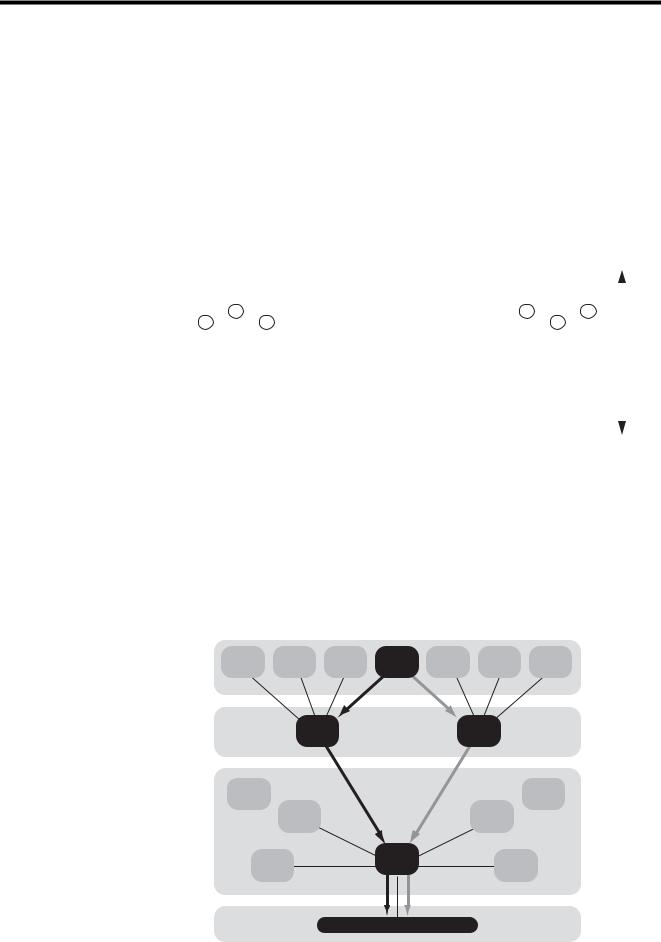
EtherNet/IP is a standard network in which the CIP (Common Industrial Protocol), defined by EN50170 and IEC61158 standards and proven in DeviceNet, is implemented over standard Ethernet and TCP/IP protocols.
EtherNet/IP can handle the I/O messages that are used to control devices or to perform interlock communication between the controllers in real time, and also the explicit messages that check the configuration of and diagnose field devices. Since EtherNet/IP uses routing technology that is compatible with DeviceNet, it is possible to send and receive messages between devices in different networks by simply connecting EtherNet/IP and DeviceNet with a CIP router (gateway), without using additional networking and programs.
The following figures show the protocol stack configuration of EtherNet/IP (includes DeviceNet) and the protocol stack concept of EtherNet/IP.
Device profile |
Semiconductor |
|
|
|
Valve |
|
|
|
Drive |
|
|
Robot |
|
|
Others |
|
|
|||
|
|
|
|
|
|
|
|
|
|
|
|
|||||||||
|
|
|
|
|
|
|
|
|
|
|
|
|
|
|
|
|
|
|
|
|
|
|
|
|
|
|
|
|
|
|
|
|
|
|
|
|
|
|
|
|
|
|
|
|
|
|
|
|
|
CIP application layer |
|
|
|
|
|
|
||||||
|
|
|
|
|
|
|
Application object library |
|
|
|
|
|
|
|||||||
|
|
|
|
|
|
|
|
|
|
|
|
|
|
|
|
|
|
|
|
CIP |
Application |
|
|
|
|
|
CIP data management service |
|
|
||||||||||||
|
|
|
|
|
|
|
|
|||||||||||||
|
|
|
|
|
Explicit messages, I/O messages |
|
|
|
||||||||||||
|
|
|
|
|
|
|
|
|
||||||||||||
|
|
|
|
|
|
|
|
|
|
|
|
|
|
|
|
|||||
|
|
|
|
|
|
|
|
|
|
|
|
|
|
|
|
|
|
|
|
|
|
|
|
|
|
|
CIP message routing, connection control |
|
|
|
|||||||||||
|
|
|
|
|
|
|
|
|
||||||||||||
|
|
|
|
|
|
|
|
|
|
|
|
|
|
|
|
|
|
|
|
|
|
|
|
|
|
|
|
|
|
|
|
|
|
|
|
|
|
|
|
|
|
Transport |
|
Encapsulation |
|
|
|
|
|
|
|
|
|
|
|
|
|
|
||||
|
|
|
|
|
|
|
|
|
|
|
|
|
|
DeviceNet |
|
|
|
|||
|
|
TCP |
|
|
|
|
UDP |
|
|
|
|
|
|
|
|
|||||
|
|
|
|
|
|
|
|
|
|
|
Transport |
|
|
|
||||||
|
|
|
|
|
|
|
|
|
|
|
|
|
|
|
|
|
|
|||
|
|
|
|
|
|
|
|
|
|
|
|
|
|
|
|
|
|
|
|
|
Network |
|
|
|
|
IP |
|
|
|
|
|
|
|
|
|
|
|
|
|
|
|
|
|
|
|
|
|
|
|
|
|
|
|
|
|
|
|
|
|
|
|
|
Data link |
|
|
Ethernet |
|
|
|
|
|
|
|
|
CAN |
|
|
|
|||||
|
|
|
CSMA/CD |
|
|
|
|
|
|
|
|
CSMA/CD |
|
|
|
|||||
|
|
|
|
|
|
|
|
|
|
|
|
|
|
|
|
|
|
|
|
|
Physical media |
|
|
Ethernet |
|
|
|
|
|
|
|
|
DeviceNet |
|
|
|
|||||
|
|
Physical Layer |
|
|
|
|
|
|
|
|
Physical Layer |
|
|
|||||||
Fig. 1.1 Protocol Stack Configuration of EtherNet/IP (Includes DeviceNet) |
||||||||||||||||||||
Application layer |
FTP |
|
HTTP |
SMTP |
CIP |
SNMP |
BOOTP |
DHCP |
||||||||||||
|
|
|
|
|
|
|
|
|
|
|
|
|
|
|
|
|
|
|
||
Transport layer |
TCP |
UDP |
Explicit
OSPF
messages IGRP
Network layer
IP
ARP
I/O |
messages |
|
ICMP
IGMP
RARP
Data link layer |
IEEE 802.3 Ethernet |
|
Physical layer |
||
|
Fig. 1.2 Protocol Stack of EtherNet/IP
1-2
1.2 EtherNet/IP Features
1.2 EtherNet/IP Features
EtherNet/IP is a standard network configured with standard worldwide protocols (Ethernet, TCP/IP, and CIP), it has the following features since it uses standard protocols.
•Can manage and integrate entire production systems, from field devices to the internet.
•Can control, set, diagnose the device and collect data on the same Ethernet.
•Can use a previously installed Ethernet for the information system.
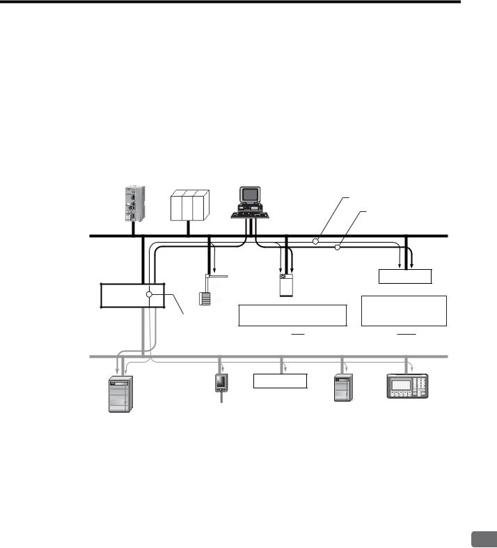
The following figure illustrates how a system that connects EtherNet/IP devices and DeviceNet using EtherNet/IP may be arrayed.
Controller |
Controller |
PC |
Device control/setting by EtherNet/IP
|
|
|
Standard Ethernet protocol |
|
|
|
|
(FTP, DHCP, etc.) |
|
EtherNet/IP |
|
|
|
|
|
|
Controller |
Distributed I/O |
|
Robot |
|
|
I/O Device |
|
CIP router |
|
for welding |
MAC ID: 00:00:xx:xx:xx:xx |
|
|
|
|
||
|
Recipe information: |
Recipe.xxx |
IP: |
192.xxx.xxx.xxx |
Routing between |
Controller information: Welding.xxx |
Mask: |
255.255.0.0 |
|
EtherNet/IP |
FTP |
|
|
DHCP |
and DeviceNet |
|
|
||
|
|
|
|
|
DeviceNet |
Distributed I/O
Drive |
Sensor |
I/O Device |
Drive |
Display unit |
Fig. 1.3 Example of EtherNet/IP (Includes DeviceNet) System Configuration
EtherNet/IP Communication
1
1-3

1.3 EtherNet/IP (CIP) Communication Types
1.3.1 Explicit Message Communication
1.3 EtherNet/IP (CIP) Communication Types
There are two kinds of CIP communication: Explicit message communication and I/O communication.
1.3.1 Explicit Message Communication
Explicit messages are used in general message communication between the client and the server (peer-to-peer communication).
•Two types of message communication is available, namely, connected message communication and unconnected message communication.
•An explicit message contains the communication destination object information and the request details.
Major Applications
Program uploading/downloading, device setting, data collection, diagnosing, etc.
1.3.2 I/O Communication
I/O communication is used for time-critical control data communication.
•Efficient communication is possible since only data is sent/received in I/O communication.
•The meaning of the data is pre-defined for each connection (communication target application object).
Major Applications
Transmission of control data for individual devices, etc.
1-4

2
263IF-01 Module
This chapter describes the external appearance and specifications of the 263IF-01 Module.
2.1 Features - - - - - - - - - - - - - - - - - - - - - - - - - - - - - - - - - - - - - - - - - - - - - - -2-2
2.1.1 I/O Communication - - - - - - - - - - - - - - - - - - - - - - - - - - - - - - - - - - - - - - - - - - - - - - - - 2-2
2.1.2 Explicit Message Communication - - - - - - - - - - - - - - - - - - - - - - - - - - - - - - - - - - - - - - 2-3
2.1.3 Engineering Communication - - - - - - - - - - - - - - - - - - - - - - - - - - - - - - - - - - - - - - - - - - 2-4
2.2 Specifications - - - - - - - - - - - - - - - - - - - - - - - - - - - - - - - - - - - - - - - - - - - -2-5
2.2.1 Hardware Specifications - - - - - - - - - - - - - - - - - - - - - - - - - - - - - - - - - - - - - - - - - - - - - 2-5
2.2.2 Transmission Specifications - - - - - - - - - - - - - - - - - - - - - - - - - - - - - - - - - - - - - - - - - - 2-6
2.2.3 Software Configuration - - - - - - - - - - - - - - - - - - - - - - - - - - - - - - - - - - - - - - - - - - - - - - 2-8
2.2.4 Operating Environment Specifications - - - - - - - - - - - - - - - - - - - - - - - - - - - - - - - - - - - 2-9
2.3 Overview - - - - - - - - - - - - - - - - - - - - - - - - - - - - - - - - - - - - - - - - - - - - - - 2-10
2.3.1 Appearance and Connectors - - - - - - - - - - - - - - - - - - - - - - - - - - - - - - - - - - - - - - - - 2-10 2.3.2 Status Indicators (LEDs) - - - - - - - - - - - - - - - - - - - - - - - - - - - - - - - - - - - - - - - - - - - - 2-10 2.3.3 Communication Status Indicators (LEDs) (Contained in the Ethernet Connector) - - - - 2-11 2.3.4 Switch Settings - - - - - - - - - - - - - - - - - - - - - - - - - - - - - - - - - - - - - - - - - - - - - - - - - - 2-11
2.4 Connection Specifications - - - - - - - - - - - - - - - - - - - - - - - - - - - - - - - - - - 2-12
2.4.1 Connector Specifications - - - - - - - - - - - - - - - - - - - - - - - - - - - - - - - - - - - - - - - - - - - 2-12
2.4.2 Cable Specifications - - - - - - - - - - - - - - - - - - - - - - - - - - - - - - - - - - - - - - - - - - - - - - 2-12
263IF-01 Module
2
2-1
2.1 Features
2.1.1 I/O Communication
2.1 Features
A 263IF-01 Module can perform I/O communication, explicit message communication and engineering communication.
2.1.1 I/O Communication
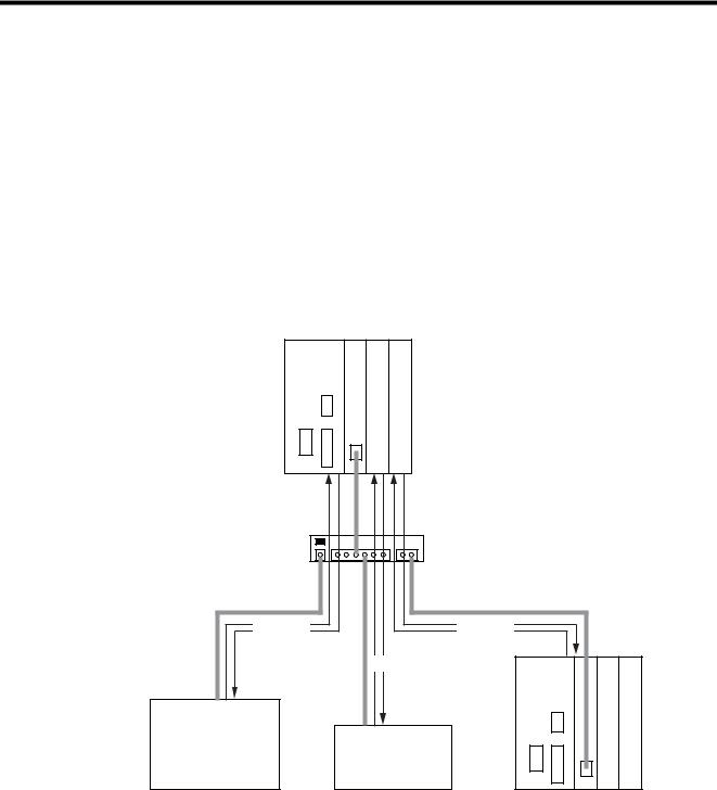
In I/O communication (Class 1), communication of time-critical control data is possible. This type of communication is mainly used between scanners and adaptors in a 1:1 or 1:N configuration.
I/O communication using the 263IF-01 Module provides both the scanner and adaptor functions and supports a maximum of 64 connected devices (scanner devices and adapter devices). The scanner and adaptor functions operate simultaneously.
The following figure illustrates communication between scanners and adaptors.
Scanner/Adaptor
MP2300 263IF-01
|
Switch |
|
I/O data |
I/O data |
|
|
I/O data |
MP2300 263IF-01 |
Controller, I/O |
Various devices |
|
|
compatible |
|
|
with EtherNet/IP |
|
Adaptor 1 |
Adaptor 2 |
Scanner 1 |
The communication trigger for an I/O communication is as follows.
Type |
Scanner/Adaptor |
Remarks |
Cyclic |
Scanner, adaptor |
Sends the data at specified intervals (at each timeup). |
|
|
|
2-2
2.1 Features
2.1.2 Explicit Message Communication
2.1.2 Explicit Message Communication
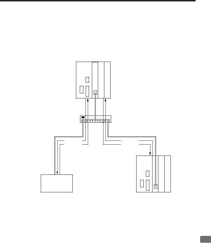
In explicit message communication, general message communication is possible.
In explicit message communication using the 263IF-01 Module, the Module provides both the client (UCMM) and server (Class 3, UCMM) functions, and is mainly used in communication between the client and server (maximum number of connected devices = 64) in 1:1 (peer-to-peer) configuration.
The following figure illustrates a layout for communication between clients and a server.
Scanner/Adaptor
MP2300 263IF-01
Switch
Command |
Command |
Response |
Response |
|
MP2300 263IF-01 |
Various devices compatible with EtherNet/IP
Client 1 |
Client 2 |
The following table shows the types of message communication and their communication triggers.
|
Communication Type |
Remarks |
||
|
|
|
Performs message communication after establishing a CIP |
|
|
|
Connected |
connection. |
|
Message |
|
message communication |
Server: Supported |
|
Communication |
|
|
Client: Not supported |
|
|
|
|
|
|
|
|
Unconnected (UCMM) |
Performs message communication without establishing a CIP |
|
|
|
message communication |
connection. |
|
|
|
|
|
|
Communication Trigger |
Driven by application object |
Sends a message upon occurrence of an event. |
||
(event) |
(Uses a message send function.) |
|||
|
|
|||
|
|
|
|
|
263IF-01 Module
2
2-3
2.1 Features
2.1.3Engineering Communication
2.1.3Engineering Communication
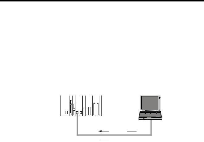
By connecting the 263IF-01 Module to the Programming Device MPE720, ladder programming and monitoring are possible through engineering communication.
The self configuration function of the MP2000-series Machine Controller enables an Ethernet connection between the personal computer where MPE720 is installed and the 263IF-01 Module, without requiring settings for connections at the 263IF-01 Module.
The Communication Manager setting on the personal computer and connection setting on the MPE720 are necessary. For details, refer to 3.3.2 Setting the Communication Manager on page 3-10, 3.5.1 Starting MPE720 Ver. 6 and Setting Communication Parameters on page 3-15 and 3.5.2 Starting MPE720 Ver. 5.xx and Setting Network Parameters on page 3-16.
The following figure illustrates a layout for connection with the MPE720.
MP2000-series Machine Controller |
Personal computer |
||||||||||||||||||||||
|
MP2200 CPU-02 SVB-01 263IF-01 262IF-01 LIO-04 LIO-04 LIO-04 LIO-01 LIO-01 |
|
|
|
|
|
|
|
|
|
|
|
|
||||||||||
|
|
|
|
|
|
|
|
|
|
|
|
|
|
|
|
|
|
|
|
|
|
|
|
|
|
|
|
|
|
|
|
|
|
|
|
|
|
|
|
|
|
|
|
|
|
|
|
|
|
|
|
|
|
|
|
|
|
|
|
|
|
|
|
|
|
|
|
|
|
|
|
|
|
|
|
|
|
|
|
|
|
|
|
|
|
|
|
|
|
|
|
|
|
|
|
MPE720 |
Command |
Response 
2-4
2.2 Specifications
2.2.1 Hardware Specifications
2.2 Specifications
This section provides specifications for the 263IF-01 Module.
2.2.1 Hardware Specifications
Item |
|
Specification |
|
|
Name |
263IF-01 |
|
|
|
|
|
|
|
|
Model |
JAPMC-CM2304-E |
|
|
|
|
|
|
|
|
Communication Port |
EtherNet/IP: 1 port |
|
|
|
|
|
|
|
|
|
Module status indicators LED |
|
|
|
|
MS |
(red/green) |
NS |
(red/green) |
|
|
|
IP |
(green) |
Indicators |
TX |
(green) |
RX |
(green) |
|
|
|
|
|
|
EtherNet/IP status indicator LED |
|
|
|
|
LINK |
(yellow) |
|
|
|
100M |
(green/orange) |
|
|
|
|
|
|
|
Switch |
INIT |
|
|
|
TEST |
|
|
|
|
|
|
|
|
|
|
|
|
|
|
Dimensions (mm) |
125 × 95 mm (H × D) |
|
|
|
|
|
|
|
|
Mass |
80 g |
|
|
|
|
|
|
|
|
263IF-01 Module
2
2-5

2.2 Specifications
2.2.2Transmission Specifications
2.2.2Transmission Specifications
|
Item |
|
Specifications |
|
|
|
100BASE-TX |
|
10BASE-T |
|
|
|
|
|
|
Interface |
|
RJ-45 |
connector |
|
|
|
|
|
|
Compliance Standard |
IEEE802.3u |
|
IEEE802.3i |
|
|
|
|
|
|
Media Access Mode |
|
CSMA/CD |
|
|
|
|
||
|
Communication Mode |
Full duplex/half duplex |
||
|
|
|
|
|
|
Modulation Method |
|
Baseband |
|
|
|
|
|
|
|
Topology |
|
Bus |
|
|
|
|
||
|
Communication Protocol |
TCP/UDP/IP/ICMP/IGMP |
||
|
|
|
|
|
|
Baud Rate |
100 Mbps |
|
10 Mbps |
Ethernet |
|
|
|
|
Maximum Number of |
2 levels |
|
4 levels |
|
Transmission |
Cascade Connections |
|
||
|
|
|
||
Specifications |
|
|
|
|
Transmission Path Length |
100 m (500 m max.*1) |
|
100 m (205 m max.*1) |
|
|
(Full length at repeater |
|
||
|
usage) |
|
|
|
|
|
|
|
|
|
|
Twisted-pair cable (UTP) |
|
Twisted-pair cable (UTP) |
|
Transmission Media |
Category 5 or 5e |
|
Category 3, 4, 5, or 5e |
|
Twisted-pair cable (STP) |
|
Twisted-pair cable (STP) |
|
|
|
|
||
|
|
Category 5 or 5e (100 Ω) |
|
Category 3, 4, 5, or 5e (100 Ω) |
|
|
|
|
|
|
Maximum Segment Length |
100 m (distance between hub and node at UTP usage) |
||
|
|
|
||
|
|
Support for auto-negotiation |
||
|
Link Function |
(not possible to fix transmission and communication modes) |
||
|
|
Support for Auto MDI/MDI-X |
||
|
|
|
||
|
IP Address |
To be set by Programming Device (DHCP and BOOTP are not supported.) |
||
|
|
|
|
|
|
|
I/O communication: |
|
|
|
Port Number |
The system uses one port at 2222 (0x08AE).*2 |
||
|
Explicit message communication: |
|||
|
|
|||
|
|
The system uses one port at 44818 (0xAF12).*2 |
||
|
Communication Protocol |
Conforms to EtherNet/IP (CIP) |
||
|
|
|
|
|
|
Device Type |
Communication adaptor |
|
|
|
|
|
|
|
|
|
Mandatory objects |
|
|
EtherNet/IP |
|
• Identity |
|
|
|
• Message Router |
|
|
|
Specifications |
|
|
|
|
|
• Ethernet Link |
|
|
|
|
|
|
|
|
|
Supported Objects*4 |
• TCP/IP Interface |
|
|
|
• Connection Manager |
|
|
|
|
|
|
|
|
|
|
Optional objects |
|
|
|
|
• Assembly |
|
|
|
|
• UCMM (Unconnected Message Manager; Non-object) |
||
|
|
• Port |
|
|
|
|
|
|
|
|
|
Level 4 |
|
|
|
Product Level |
I/O communication: Scanner and adaptor |
||
|
|
Explicit message communication: Client and server |
||
|
|
|
|
|
|
Maximum Number of |
64 units*3 |
|
|
|
Connectable I/O Devices |
(Does not include the devices used for explicit message communication) |
||
|
|
|
||
|
Max. Number of I/O Bytes |
Inputs/outputs: 8192 bytes each*3 per system (Total number of bytes of input/ |
||
I/O |
output data exchanged among all connected devices) |
|||
Communication |
|
Inputs/outputs: 500 bytes each*2 per device |
||
Specifications |
|
|
|
|
Communication Mode |
Scanner, adaptor |
|
|
|
|
|
|
|
|
|
Communication Mode at |
Simultaneous start of scanners and adaptors |
||
|
Startup |
|||
|
|
|
|
|
|
|
|
|
|
|
Communication Trigger |
Cyclic |
|
|
|
|
|
|
|
2-6

|
|
|
2.2 Specifications |
|
|
|
|
|
|
|
2.2.2 Transmission Specifications |
|
|
|
|
|
|
Item |
Specifications |
|
|
|
|
|
|
Max. Number of |
64 units*3 |
|
|
Connectable Devices for |
|
|
|
Explicit Message |
(Number of devices that can communicate simultaneously: 10) |
|
|
Communication |
|
|
|
|
|
|
|
Number of Message |
10 |
|
|
Channels |
|
|
Explicit |
|
|
|
|
|
|
|
Max. Number of Message |
504 bytes*2 |
|
|
Message |
Bytes |
|
|
Specifications |
|
|
|
Function for Execution |
MSG-SND Function |
|
|
|
||
|
|
|
|
|
|
Communication Mode |
Client and server |
|
|
|
|
|
|
Connection Type |
Unconnected type (UCMM) |
|
|
When the Module functions as a server, connected type (class 3) is |
|
|
|
|
also supported. |
|
|
Communication Trigger |
Application object driven |
|
|
|
|
1. The maximum transmission path length when a switching hub is used. Use a switching hub for the Ethernet (available at any electronics shop)
(A product manufactured by the Japan Electrical Manufacturers' Association is recommended.)
2. EtherNet/IP (CIP) specifications
3. Restrictions due to MP2000-series Machine Controller specifications
4. The following table describes objects in detail.
|
|
Optional/ |
|
|
Object Name |
Class ID |
Mandatory |
Description |
|
|
|
(See*2 above) |
|
|
|
|
|
• Retains the identification information of a device. The |
|
|
|
|
device identification information can be obtained by |
|
|
|
|
reading the attributes of an Identity object. |
|
Identity |
0x01 |
Mandatory |
• Supports device reset processing to be activated |
|
through the network. |
||||
|
|
|
||
|
|
|
<Attributes> |
|
|
|
|
Vendor ID, device type, product code, revision, status, |
|
|
|
|
product serial number, product name, state, etc. |
|
|
|
|
|
|
|
|
|
• Transfers the received explicit request to the specified |
|
Message Router |
|
|
object. |
|
0x02 |
Mandatory |
• To be specified in the connection path used when |
||
|
|
|
establishing the connection for explicit message |
|
|
|
|
communication. |
|
|
|
|
|
|
Assembly |
0x04 |
Optional |
Provides the access map for accessing attributes or I/O |
|
data in a device. |
||||
|
|
|
||
|
|
|
|
|
|
|
|
• Issues and receives the Forward_Open service and |
|
Connection Manager |
0x06 |
Mandatory |
creates the CIP connection. |
|
(conditional) |
• Retains the CIP connection information and secures the |
|||
|
|
|||
|
|
|
necessary internal resources. |
|
|
|
|
|
|
Port |
|
|
• Retains the information of the connection ports that can |
|
0xF4 |
Optional |
be used in the CIP network. |
||
|
|
|
• Used when searching for the CIP routing information. |
|
|
|
|
|
|
Ethernet Link |
0xF5 |
Mandatory |
Provides the EtherNet/IP interface. |
|
(conditional) |
||||
|
|
|
||
|
|
|
|
|
TCP/IP Interface |
0xF6 |
Mandatory |
Provides the EtherNet/IP interface. |
|
(conditional) |
||||
|
|
|
||
|
|
|
|
263IF-01 Module
2
2-7
2.2 Specifications
2.2.3Software Configuration
2.2.3Software Configuration
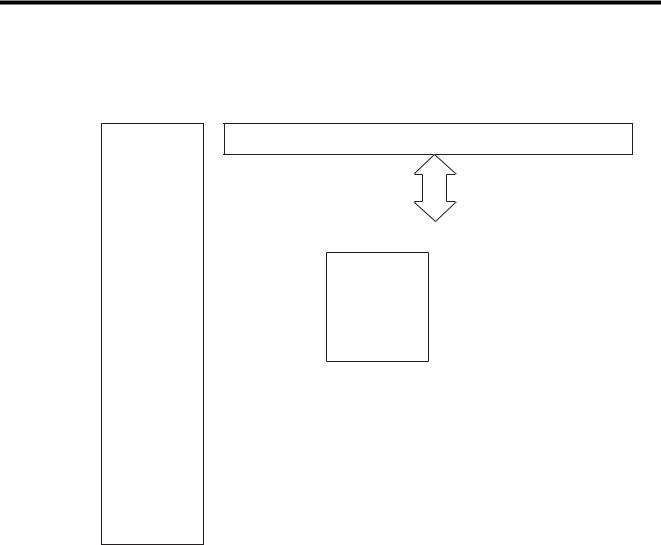
The following figure illustrates the software configuration that provides the 263IF-01 Module functions.
CPU Module
Application layer |
|
|
Host interface |
Presentation layer |
|
|
|
|
|
|
|
Session layer |
|
Scanner/adaptor |
|
|
|
|
|
|
|
function |
|
|
|
|
Engineering |
|
|
|
|
|
|
EtherNet/IP |
tool interface |
|
|
|
|
|
|
communication |
|
|
|
protocol |
|
|
|
|
|
Transport layer |
|
|
TCP/UDP |
|
|
|
|
Network layer |
|
|
ARP/IP/ICMP/IGMP |
|
|
|
|
Data link layer |
|
|
Ethernet |
|
|
|
|
Physical layer |
|
|
10BASE-T/100BASE-TX |
|
|
|
|
The following table provides the details of the individual protocols.
Protocol |
Details |
TCP (Transmission Control Protocol) |
Connection type transport layer protocol |
|
|
UDP (User Datagram Protocol) |
Connection type transport layer protocol |
|
|
IP (Internet Protocol) |
Protocol that establishes the communication path between computers |
|
|
ICPM (Internet Control Message Protocol) |
Protocol that handles error control in the IP protocol |
|
|
IGMP (Internet Group Management Protocol) |
Protocol used for IP multicast |
|
|
ARP (Address Resolution Protocol) |
Converts an IP address into a MAC address. |
|
|
2-8

|
|
|
|
|
2.2 Specifications |
|
|
|
|
|
|
|
|
|
|
|
2.2.4 Operating Environment Specifications |
2.2.4 Operating Environment Specifications |
|
||||
|
|
|
|
|
|
|
|
Item |
|
Specifications |
|
|
|
|
|
|
|
|
|
|
Ambient |
0 to +55 °C |
|
|
|
|
Operating |
|
|
|
|
|
Temperature |
|
|
|
|
|
|
|
|
|
|
|
Ambient |
−25 to +85°C |
|
|
|
|
Storage |
|
|
|
|
|
Temperature |
|
|
|
|
|
|
|
|
|
|
|
Ambient |
|
|
|
Environmental |
|
Operating |
30% to 95% RH (with no condensation) |
|
|
|
Humidity |
|
|
|
|
Conditions |
|
|
|
|
|
|
|
|
|
|
|
|
Ambient |
|
|
|
|
|
|
|
|
|
|
|
|
Storage |
5% to 95% RH (with no condensation) |
|
|
|
|
Humidity |
|
|
|
|
|
|
|
|
|
|
|
Pollution Level |
Pollution level: 2 (conforming to JIS B3502) |
|
|
|
|
|
|
|
|
|
|
Corrosion |
There must be no combustible or corrosive gas. |
|
|
|
|
Resistance |
||
|
|
|
|
|
|
|
|
|
|
|
|
|
|
|
Operating |
2,000 m above sea level or lower |
|
|
|
|
Altitude |
|
|
|
|
|
|
|
|
|
|
|
|
|
|
|
|
|
|
Conforming to JIS B3502 |
|
|
|
|
Vibration |
(1) Frequency: 16.7 Hz |
Vibration strength: 14.7 m/s2 |
|
Mechanical |
|
Resistance |
(2) Frequency: 10 to 57 Hz |
Vibration strength: 0.075 mm of single-amplitude |
|
Operating |
|
|
(3) Frequency: 57 to 150 Hz |
Vibration strength: 9.8 m/s2 of fixed acceleration |
|
Conditions |
|
|
|
|
|
|
Shock |
Conforming to JIS B3502 |
|
|
|
|
|
|
||
|
|
|
Peak acceleration of 147 m/s2 (15G) twice for 11 ms each in the X, Y, and Z |
||
|
|
|
Resistance |
||
|
|
|
directions |
|
|
|
|
|
|
|
|
|
|
|
|
|
|
|
Electrical |
|
|
Conforming to EN 61000-6-2, EN 55011 (Group 1, Class A) |
|
|
|
Noise |
Power supply noise (FT noise): |
±2 kV min., for one minute |
|
|
Operating |
|
Radiation noise (FT noise): |
±1 kV min., for one minute |
|
|
|
Resistance |
|||
|
Conditions |
|
Ground noise (impulse noise): |
±1 kV min., for ten minutes |
|
|
|
|
|||
|
|
|
|
Electrostatic noise (contact discharge method): ±6 kV min., ten times |
|
|
|
|
|
|
|
|
Installation |
|
Ground |
Ground to 100 Ω max. |
|
|
Requirements |
|
Cooling Method |
Natural cooling |
|
|
|
|
|
|
|
263IF-01 Module
2
2-9
2.3 Overview
2.3.1 Appearance and Connectors
2.3Overview
2.3.1Appearance and Connectors
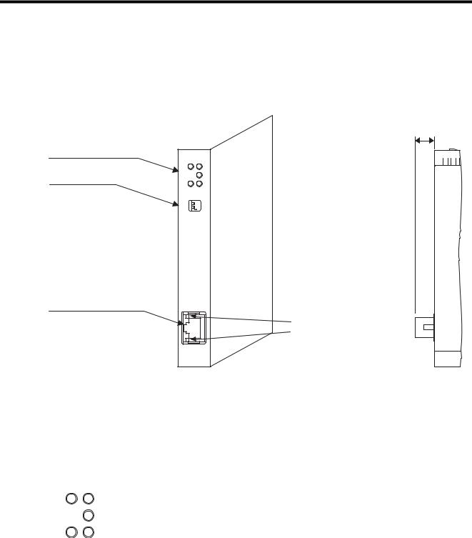
The following illustration shows the appearance of the 263IF-01 Module and provides the external dimensions of the connector.
Status indicators (LEDs)
Switches
EtherNet/IP connector 100Base-TX/10Base-T
263IF-01 |
|
MS |
NS |
|
IP |
TX |
RX |
INIT |
|
TEST |
NO |
OFF |
ON |
EtherNet/IP |
|
LINK |
|
100M |
|
(25 mm)
Communication status indicator (LED)
(contained in the connector)
2.3.2 Status Indicators (LEDs)
The following table shows the status of the 263IF-01 Module indicated by the LED indicators.
|
|
Indicator |
Color |
Meaning When Lit |
Meaning When Flashing |
Meaning When Not Lit |
|
|
|
Green |
Operating normally |
Device not set |
Module power supply |
|
|
|
|
|
|
|
|
|
MS |
Red |
Module error |
Module error |
|
|
|
disconnected/Startup |
||||
|
|
(Unrecoverable) |
(Recoverable) |
|||
|
|
|
|
failure |
||
|
|
|
|
|
|
|
|
|
|
Alternately flashing green/red |
During self-testing |
||
|
|
|
|
|||
|
|
|
|
|
|
|
|
|
|
Green |
|
Connection being estab- |
|
MS |
NS |
|
Operating normally |
lished, or no I/O alloca- |
Communication power |
|
|
IP |
NS |
|
|
tions |
|
|
|
|
|
supply disconnected/No |
||
|
Red |
Error |
Communication error |
|||
|
|
|
IP address |
|||
TX |
RX |
|
(Duplicated IP address) |
(Timeout) |
||
|
|
|
||||
|
|
|
Alternately flashing green/red |
During self-testing |
|
|
|
|
|
|
|
|
|
|
|
IP |
Green |
IP address acquisition |
– |
IP address acquisition not |
|
|
completed |
completed |
|||
|
|
|
|
|
||
|
|
|
|
|
|
|
|
|
TX |
Green |
Sending data |
– |
Not sending data |
|
|
|
|
|
|
|
|
|
RX |
Green |
Receiving data |
– |
Not receiving data |
|
|
|
|
|
|
|
For details on the Module status indicated by the LED indicators, refer to 6.1 Status Indication by LED Indicators on page 6-2.
2-10

2.3 Overview
2.3.3Communication Status Indicators (LEDs) (Contained in the Ethernet Connector)
2.3.3Communication Status Indicators (LEDs) (Contained in the Ethernet Connector)
The indicators (LEDs) contained in the EtherNet/IP connector indicate the status of EtherNet/IP communication.
Indicator |
Color |
Meaning When Lit |
Meaning When Not Lit |
|
LINK |
Yellow |
EtherNet/IP link established |
EtherNet/IP link not established |
|
|
|
|
|
|
100M |
Green/orange |
Green: 100 Mbps |
10 Mbps or not connected |
|
(Orange: 1 Gbps) |
||||
|
|
|
||
|
|
|
|
2.3.4 Switch Settings
The following table shows the 263IF-01 Module switch settings.
INIT
TEST
OFF ON
Label |
Name |
Status |
Function |
Factory |
|
(Switch No.) |
Setting |
||||
|
|
|
|||
|
|
|
|
|
|
INIT |
Transmission Parameters Star- |
ON |
Initial startup |
|
|
tup Selection |
|
|
OFF |
||
(2) |
OFF |
Normal operation mode |
|||
(For Programming Device) |
|
||||
|
|
|
|
||
|
|
|
|
|
|
TEST |
Operating Mode Selection |
ON |
Reserved by the system. |
OFF |
|
|
|||||
(1) |
OFF |
Always set to OFF. |
|||
|
|
||||
|
|
|
|
|
Always leave the unused switches (Nos. 3 and 4), located behind the faceplate, OFF.
263IF-01 Module
2
2-11

2.4 Connection Specifications
2.4.1 Connector Specifications
2.4Connection Specifications
2.4.1Connector Specifications
This section explains the connector specifications for the 263IF-01 Module.
( 1 ) Connector Specifications
Connector |
Name |
Connector |
No. of |
|
Connector Model |
|
||||
|
Shape |
Name |
Pins |
Module |
|
Cable |
Manufacturer |
|||
|
|
|
||||||||
|
|
|
|
|
|
|
|
|
|
|
|
EtherNet/IP |
|
|
|
|
|
|
|
||
LINK |
|
|
|
JOG-0001NL |
|
|
|
|||
|
|
|
|
EtherNet/IP |
EtherNet/IP |
8 |
|
– |
|
|
|
|
|
|
|
|
|||||
|
|
|
|
(LED/Pulse transformer |
|
Pulse Engineering |
||||
|
|
|
|
|
||||||
|
|
|
|
|
|
|
built-in modular jack) |
|
|
|
|
|
|
|
|
|
|
|
|
|
|
|
|
|
|
|
|
|
|
|
|
|
100M |
|
|
|
|
|
|
|
|||
|
|
|
|
|
|
|
|
|
|
|
( 2 ) Connector Pin Arrangement
The connector is used to connect the 263IF-01 Module to the devices in the EtherNet/IP network via an EtherNet/IP connection.
EtherNet/IP
LINK
100M
Pin |
Signal Name |
I/O |
Description |
|
Number |
||||
|
|
|
||
|
|
|
|
|
1 |
TXD+ |
O |
Send data +side |
|
|
|
|
|
|
2 |
TXD- |
O |
Send data -side |
|
|
|
|
|
|
3 |
RXD+ |
I |
Receive data +side |
|
|
|
|
|
|
4 |
– |
– |
– |
|
|
|
|
|
|
5 |
– |
– |
– |
|
|
|
|
|
|
6 |
RXD- |
I |
Receive data -side |
|
|
|
|
|
|
7 |
– |
– |
– |
|
|
|
|
|
|
8 |
– |
– |
– |
|
|
|
|
|
2.4.2 Cable Specifications
Yaskawa does not provide EtherNet/IP cables. Obtain commercially available category 5 cross or straight cables.
The AUTO MDI/MDI-X function of the 263IF-01 Module automatically distinguishes between cross and straight cables.
2-12

3
Mounting and Starting the Module
This chapter describes how to connect the 263IF-01 Module and start the system, focusing on mounting the 263IF-01 Module, communication process setting, and self-configuration.
3.1 Applicable Machine Controllers and Supported Versions - - - - - - - - - - - - -3-2
3.1.1 Applicable Machine Controllers - - - - - - - - - - - - - - - - - - - - - - - - - - - - - - - - - - - - - - - - 3-2 3.1.2 Supported CPU and MPE720 Versions - - - - - - - - - - - - - - - - - - - - - - - - - - - - - - - - - - 3-2
3.2 Mounting and Removing a Module on the Machine Controller - - - - - - - - - -3-3
3.2.1 Mounting a 263IF-01 Module - - - - - - - - - - - - - - - - - - - - - - - - - - - - - - - - - - - - - - - - - 3-3 3.2.2 Removing a 263IF-01 Module - - - - - - - - - - - - - - - - - - - - - - - - - - - - - - - - - - - - - - - - - 3-6
3.3 Setting the Communication Manager - - - - - - - - - - - - - - - - - - - - - - - - - - -3-8
3.3.1 Preparation of the Personal Computer - - - - - - - - - - - - - - - - - - - - - - - - - - - - - - - - - - - 3-8 3.3.2 Setting the Communication Manager - - - - - - - - - - - - - - - - - - - - - - - - - - - - - - - - - - - 3-10
3.4 Self-configuration - - - - - - - - - - - - - - - - - - - - - - - - - - - - - - - - - - - - - - - - 3-14
3.4.1 Executing Self-configuration - - - - - - - - - - - - - - - - - - - - - - - - - - - - - - - - - - - - - - - - - 3-14
3.5 Starting the MPE720, and Setting Communication or Network Parameters 3-15
3.5.1 Starting MPE720 Ver. 6 and Setting Communication Parameters - - - - - - - - - - - - - - - 3-15 3.5.2 Starting MPE720 Ver. 5.xx and Setting Network Parameters - - - - - - - - - - - - - - - - - - 3-16
Mounting and Starting the Module
3
3-1

3.1 Applicable Machine Controllers and Supported Versions
3.1.1 Applicable Machine Controllers
3.1Applicable Machine Controllers and Supported Versions
3.1.1Applicable Machine Controllers
The MP2000-series Machine Controllers to which the 263IF-01 Modules can be mounted are listed in the following table.
|
|
|
|
Max. No. of |
|
|
|
|
Name |
Model |
Connectable |
Remarks |
|
|
|
|
|
Modules |
|
|
|
|
|
|
|
|
|
|
|
Base Unit with 100/ |
JEPMC-BU2200 |
|
The maximum number of connectable Modules |
|
MP |
|
200-VAC input 1 |
|
|||
|
|
8 modules |
is the total for the maximum expansion to four |
|||
2200 |
|
|
|
|||
|
Base Unit with |
|
||||
|
JEPMC-BU2210 |
|
Racks. 2 |
|||
|
|
24-VDC input 1 |
|
|||
|
|
|
|
|
||
MP2300 |
|
JEPMC-MP2300 |
2 modules |
– |
||
|
|
|
|
|
||
MP2310 |
|
JEPMC-MP2310-E |
3 modules |
– |
||
|
|
|
|
|||
MP2300S |
JEPMC-MP2300S-E |
1 module |
– |
|||
|
|
|
|
|
|
|
|
|
|
|
|
The 263IF-01 Modules can be mounted on the |
|
MP2100M |
JAPMC-MC2140 |
8 modules |
Expansion Racks (which use the MP2200 Base |
|||
Unit) connected to an Expansion Interface |
||||||
|
|
|
|
|
||
|
|
|
|
|
Board (MP2100MEX, model: JAPMC- |
|
|
|
|
|
|
EX2100) mounted on the Machine Controller. |
|
MP2500MD |
JAPMC-MC2540-D |
8 modules |
The maximum number of connectable Modules |
|||
is the total for the maximum expansion to three |
||||||
|
|
|
|
|
||
|
|
|
|
|
Racks. 2 |
|
* 1. One of the following CPU Module is required.
Name |
Model |
Remarks |
CPU-01 |
JAPMC-CP2200 |
– |
|
|
|
CPU-02 |
JAPMC-CP2210 |
With one slot for CF card and one USB port |
|
|
|
CPU-03 |
JAPMC-CP2220-E |
With one slot for CF card and one Ethernet port |
|
|
|
CPU-04 |
JAPMC-CP2230-E |
With one Ethernet port |
|
|
|
2. An EXIOIF Inter-Rack Connection Module (model: JAPMC-EX2200) is required to add Expansion Racks.
The 263IF-01 Modules cannot be mounted on the following MP2000-series Machine Controllers: MP2100, MP2400, MP2500, MP2500M, and MP2500D.
3.1.2Supported CPU and MPE720 Versions
The following table lists the CPU and MPE720 versions that can be used with the 263IF-01 Module.
Machine Controller |
|
Supported Versions |
|||
CPU |
MPE720 (CPMC-720) |
MPE720 Ver. 6 (CPMC-770) |
|||
|
|
||||
|
|
|
|
|
|
|
CPU-01 |
Ver. 2.64 or later |
Ver. 5.42 or later |
Ver. 6.08 or later |
|
|
|
|
|
|
|
MP2200 |
CPU-02 |
Ver. 2.64 or later |
Ver. 5.42 or later |
Ver. 6.08 or later |
|
|
|
|
|
||
CPU-03 |
Ver. 2.70 or later |
Ver. 5.50 or later |
Ver. 6.20 or later |
||
|
|||||
|
|
|
|
|
|
|
CPU-04 |
Ver. 2.72 or later |
Ver. 5.52 or later |
Ver. 6.22 or later |
|
|
|
|
|
|
|
MP2300 |
|
Ver. 2.64 or later |
Ver. 5.42 or later |
Ver. 6.08 or later |
|
|
|
|
|
|
|
MP2310 |
|
Ver. 2.64 or later |
Ver. 5.42 or later |
Ver. 6.08 or later |
|
|
|
|
|
|
|
MP2300S |
|
Ver. 2.64 or later |
Ver. 5.42 or later |
Ver. 6.08 or later |
|
|
|
|
|
|
|
MP2100M |
|
Ver. 2.64 or later |
Ver. 5.42 or later |
Ver. 6.08 or later |
|
|
|
|
|
|
|
MP2500MD |
|
Ver. 2.64 or later |
Ver. 5.42 or later |
Ver. 6.08 or later |
|
|
|
|
|
|
|
3-2
Loading...