


 MP3200iec
Machine Controller
Hardware Manual
Type: MP3200iec
To properly use the product, read this manual thoroughly and retain for easy reference, inspection,
and maintenance. Ensure the end user receives this manual.
YAI-SIA-IEC-5

Table of Contents
1. Definition of Terms. . . . . . . . . . . . . . . . . . . . . . . . . . . . . . . . . . . . . . . . . . . . . . . . . . . . . . . 5 2. System Configuration Example . . . . . . . . . . . . . . . . . . . . . . . . . . . . . . . . . . . . . . . . . . . . 6 3. Component Part Numbers. . . . . . . . . . . . . . . . . . . . . . . . . . . . . . . . . . . . . . . . . . . . . . . . . 7 4. Power Supply Units . . . . . . . . . . . . . . . . . . . . . . . . . . . . . . . . . . . . . . . . . . . . . . . . . . . . . . 8 5. Power Supply Unit Specifications . . . . . . . . . . . . . . . . . . . . . . . . . . . . . . . . . . . . . . . . . 10 6. CPU Specifications . . . . . . . . . . . . . . . . . . . . . . . . . . . . . . . . . . . . . . . . . . . . . . . . . . . . . 13 7. CPU External Appearance and Indicators . . . . . . . . . . . . . . . . . . . . . . . . . . . . . . . . . . . 14 8. Base Unit Installation and Operating Conditions . . . . . . . . . . . . . . . . . . . . . . . . . . . . . 15 9. Installation . . . . . . . . . . . . . . . . . . . . . . . . . . . . . . . . . . . . . . . . . . . . . . . . . . . . . . . . . . . . 17 10. DIP Switch Settings . . . . . . . . . . . . . . . . . . . . . . . . . . . . . . . . . . . . . . . . . . . . . . . . . . . . 27 11. LED Indicators . . . . . . . . . . . . . . . . . . . . . . . . . . . . . . . . . . . . . . . . . . . . . . . . . . . . . . . . 29 12. Self-Configuration . . . . . . . . . . . . . . . . . . . . . . . . . . . . . . . . . . . . . . . . . . . . . . . . . . . . . 30 13. MECHATROLINK-III Specifications. . . . . . . . . . . . . . . . . . . . . . . . . . . . . . . . . . . . . . . . 31 14. MECHATROLINK-III Network Topologies. . . . . . . . . . . . . . . . . . . . . . . . . . . . . . . . . . . 32 15. MECHATROLINK-III Synchronization between Modules . . . . . . . . . . . . . . . . . . . . . . 35 16. Devices Connectable via MECHATROLINK-III. . . . . . . . . . . . . . . . . . . . . . . . . . . . . . . 37 17. Connecting the RLY OUT Connector . . . . . . . . . . . . . . . . . . . . . . . . . . . . . . . . . . . . . . 38 18. Ethernet Connector Details . . . . . . . . . . . . . . . . . . . . . . . . . . . . . . . . . . . . . . . . . . . . . . 39 19. Option Module - AI-01 (Analog Input) Module . . . . . . . . . . . . . . . . . . . . . . . . . . . . . . 42 20. Option Module - AO-01 (Analog Output) Module . . . . . . . . . . . . . . . . . . . . . . . . . . . . 48 21. Option Module - DO-01 (Digital Output) Module . . . . . . . . . . . . . . . . . . . . . . . . . . . . . 51 22. Option Module - LIO-01/02 Module . . . . . . . . . . . . . . . . . . . . . . . . . . . . . . . . . . . . . . . . 55 23. Option Module - LIO-04/05 Modules . . . . . . . . . . . . . . . . . . . . . . . . . . . . . . . . . . . . . . . 63 24. Option Module - LIO-06 Module . . . . . . . . . . . . . . . . . . . . . . . . . . . . . . . . . . . . . . . . . . 75 25. Option Module – 218IF-Y1 . . . . . . . . . . . . . . . . . . . . . . . . . . . . . . . . . . . . . . . . . . . . . . . 85 26. Terminal Block Kit CBK-U-MP2A-xx. . . . . . . . . . . . . . . . . . . . . . . . . . . . . . . . . . . . . . . 87 27. Terminal Block Kit CBK-U-MP2B-xx. . . . . . . . . . . . . . . . . . . . . . . . . . . . . . . . . . . . . . . 88 28. Terminal Block Kit CBK-U-MP2C-xx. . . . . . . . . . . . . . . . . . . . . . . . . . . . . . . . . . . . . . . 89 29. Cable Shielding, Segregation and Noise Immunity . . . . . . . . . . . . . . . . . . . . . . . . . . 90
YASKAWA America, Inc. MP3200iec Hardware Manual YAI-SIA-IEC-5 |
3 |

Copyright © 2013 YASKAWA AMERICA, INC.
All rights reserved. No part of this publication may be reproduced, stored in a retrieval system, or transmitted, in any form, or by any means, mechanical, electronic, photocopying, recording, or otherwise, without the prior written permission of Yaskawa. No patent liability is assumed with respect to the use of the information contained herein. Moreover, because Yaskawa is constantly striving to improve its high-quality products, the information contained in this manual is subject to change without notice. Every precaution has been taken in the preparation of this manual.
4 |
YASKAWA America, Inc. MP3200iec Hardware Manual YAI-SIA-IEC-5 |

Nevertheless, Yaskawa assumes no responsibility for errors or omissions. Neither is any liability assumed for damages resulting from the use of the information contained in this publication.
5 |
YASKAWA America, Inc. MP3200iec Hardware Manual YAI-SIA-IEC-5 |

6 |
YASKAWA America, Inc. MP3200iec Hardware Manual YAI-SIA-IEC-5 |
1 Definition of Terms
1 Definition of Terms
This section defines terms that have specific meanings in this manual.
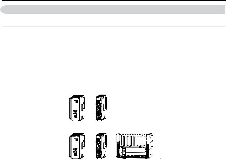
Basic Units
“Basic Unit” is a collective term that refers to the three Units in the following table.
Unit Name |
Primary Function |
|
Power Supply Unit |
Supplies the power that is needed for the operation of the Units that are connected to each other and to |
|
any Optional Modules that are connected in the Controller. |
||
|
||
CPU Unit |
Stores the module definitions and programs, and interprets the programs. The CPU Unit also controls |
|
the Optional Modules. |
||
|
||
Base Unit |
Used to mount Optional Modules. |
The Basic Units are typically connected as shown in the following examples.
+
Power |
CPU Unit |
|
Supply Unit |
||
|
+ 


 +
+
Power |
CPU Unit |
Base Unit |
|
Supply Unit |
|||
|
|
YASKAWA America, Inc. MP3200iec Hardware Manual YAI-SIA-IEC-5 |
5 |
2 System Configuration Example
2 System Configuration Example
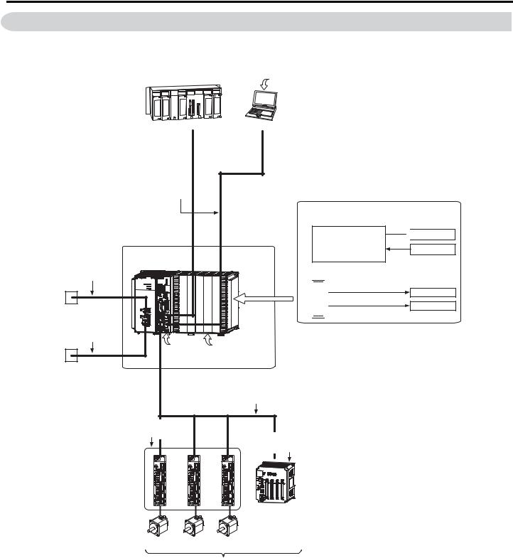
The following figure shows a typical system configuration.
 MotionWorks IEC version 2.4 or higher
|
|
|
|
|
|
|
|
|
|
|
|
|
|
|
|
|
|
|
|
|
|
|
|
|
|
|
|
|
|
|
|
|
|
|
|
|
|
|
|
|
Another PLC |
PC |
|||||
Ethernet
Ethernet
Ethernet communications cables 
|
MP3200iec |
RLYOUT |
components |
|
|
connector cable |
|
24-VDC power |
|
|
supply, AC power |
|
|
supply, or status |
|
|
monitoring device |
|
|
Power supply cable |
|
|
|
Battery |
Front cover |
24-VDC power |
|
for unused slot |
|
|
|
supply or AC |
MECHATROLINK-III |
|
power supply |
||
|
|
MECHATROLINK-III Cable |
|
SERVOPACK with |
|
|
MECHATROLINK-III |
|
|
Communications |
I/O Module with |
|
|
MECHATROLINK-III |
|
|
Communications |
Optional Modules
I/O Modules
LIO-01 |
LIO-02 |
LIO-04 |
LIO-05 |
LIO-06 |
DO-01 |
AI-01 |
AO-01 |
|
|
|
|
|
|
|
|
Communications Modules

 218IF-Y1

 External outputs
External inputs
RS-232C
Ethernet
I/O
Servomotor Servomotor Servomotor
Up to 62 stations, including I/O
6 |
YASKAWA America, Inc. MP3200iec Hardware Manual YAI-SIA-IEC-5 |

3 Component Part Numbers
3 Component Part Numbers
|
|
System Components |
|
Type |
Part Number |
Description |
|
|
PMC-U-MP32004 |
CPU, MP3200iec, 4 axis |
|
|
PMC-U-MP32008 |
CPU, MP3200iec, 8 axis |
|
CPU |
PMC-U-MP32016 |
CPU, MP3200iec, 16 axis |
|
|
PMC-U-MP32032 |
CPU, MP3200iec, 32 axis |
|
|
PMC-U-MP32062 |
CPU, MP3200iec, 62 axis |
|
Power Supply |
JEPMC-PSA3012-E |
POWER SUPPLY, 100V/200V, MP3200 |
|
JEPMC-PSD3012-E |
POWER SUPPLY, 24VDC, MP3200 |
||
|
|||
|
JEPMC-BUB3003-E |
BASE UNIT, 3 SLOTS, MP3200 |
|
Base Unit |
JEPMC-BUB3005-E |
BASE UNIT, 5 SLOTS, MP3200 |
|
|
JEPMC-BUB3008-E |
BASE UNIT, 8 SLOTS, MP3200 |
|
|
JAPMC-AN2300 |
Analog Inputs (AI-01) |
|
|
JAPMC-AN2310-E |
Analog Outputs (AO-01) |
|
|
JAPMC-DO2300 |
Digital Output Module (DO-01) |
|
|
JAPMC-IO2300-E |
Digital I/O Module (LIO-01) |
|
Option Card |
JAPMC-IO2301-E |
Digital I/O Module (LIO-02) |
|
|
JAPMC-IO2303 |
Digital I/O Module (LIO-04) |
|
|
JAPMC-IO2304 |
Digital I/O Module (LIO-05) |
|
|
JAPMC-IO2305-E |
Digital Multi-Function I/O Module (LIO-06) |
|
|
JAPMC-CM2301-E |
Ethernet & RS232C Communication (218IF-Y1) |
|
|
JEPMC-MT2000-E |
HUB, MECHATROLINK-III NETWORK, 8 SLAVE PORTS |
|
MECHATROLINK |
JEPMC-MT2020-E |
ADAPTER, ETHERNET TO MECHATROLINK |
|
JEPMC-MTD2310-E |
I/O MODULE, MECHATROLINK NETWORK, 64 IN, 64 OUT |
||
Network |
|||
JEPMC-MTA2900-E |
ANALOG MODULE, MECHATROLINK NETWORK, 8 INPUT |
||
|
|||
|
JEPMC-MTA2910-E |
ANALOG MODULE, MECHATROLINK NETWORK, 4 OUTPUT |
|
|
JEPMC-W6012-A2-E |
MECHATROLINK-III CABLE, 0.2 M |
|
|
JEPMC-W6012-A5-E |
MECHATROLINK-III CABLE, 0.5 M |
|
|
JEPMC-W6012-01-E |
MECHATROLINK-III CABLE, 1.0 M |
|
|
JEPMC-W6012-02-E |
MECHATROLINK-III CABLE, 2.0 M |
|
|
JEPMC-W6012-03-E |
MECHATROLINK-III CABLE, 3.0 M |
|
MECHATROLINK |
JEPMC-W6012-04-E |
MECHATROLINK-III CABLE, 4.0 M |
|
Cables |
JEPMC-W6012-05-E |
MECHATROLINK-III CABLE, 5.0 M |
|
|
JEPMC-W6012-10-E |
MECHATROLINK-III CABLE, 10 M |
|
|
JEPMC-W6012-20-E |
MECHATROLINK-III CABLE, 20 M |
|
|
JEPMC-W6012-30-E |
MECHATROLINK-III CABLE, 30 M |
|
|
JEPMC-W6012-40-E |
MECHATROLINK-III CABLE, 40 M |
|
|
JEPMC-W6012-50-E |
MECHATROLINK-III CABLE, 50 M |
|
|
JEPMC-BA3001 |
Replacement Battery |
|
Accessories |
JEPMC-OP2300 |
Option Slot Cover |
|
JEPMC-OP3001 |
Replacement Power Supply Side Cover |
||
|
|||
|
JEPMC-OP3002 |
Replacement Option Base Side Cover |
YASKAWA America, Inc. MP3200iec Hardware Manual YAI-SIA-IEC-5 |
7 |
4 Power Supply Units
4 Power Supply Units
The Power Supply Unit supplies the connected Units and Optional Modules with the power needed to operate. There are two Power Supply Units available: an AC Power Supply Unit and a DC Power Supply Unit.
This section shows the appearance and part names of the Power Supply Unit and describes the indicators and connectors.
Appearance and Part Names
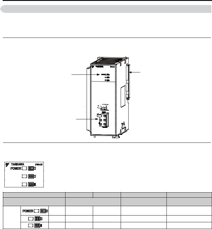
The following figure shows the appearance of the Power Supply Unit and the part names.
Indicators |
Unit connector |
|
RLYOUT connector 


Power connector
Indicators
These indicators show the load on the Power Supply Unit.
|
Output Current |
8.9 A or less |
9.0 to 11.4 A |
11.5 to 13.9 A <1> |
14.0 A or more <1> |
|
Load |
Normal: Within power supply |
Normal: Maximum power |
Error: Over power supply |
|
|
capacity |
supply capacity |
capacity |
||
|
|
||||
|
Green |
z |
z |
z |
{ |
|
Appendix |
||||
|
|
|
|
|
|
Indicator |
Yellow |
{ |
z |
z |
{ |
|
|||||
|
Red |
{ |
{ |
z |
{ |
<1> Reduce the number of Optional Modules that are connected.
Note: z: Lit, {: Not lit.
8 |
YASKAWA America, Inc. MP3200iec Hardware Manual YAI-SIA-IEC-5 |
4 Power Supply Units
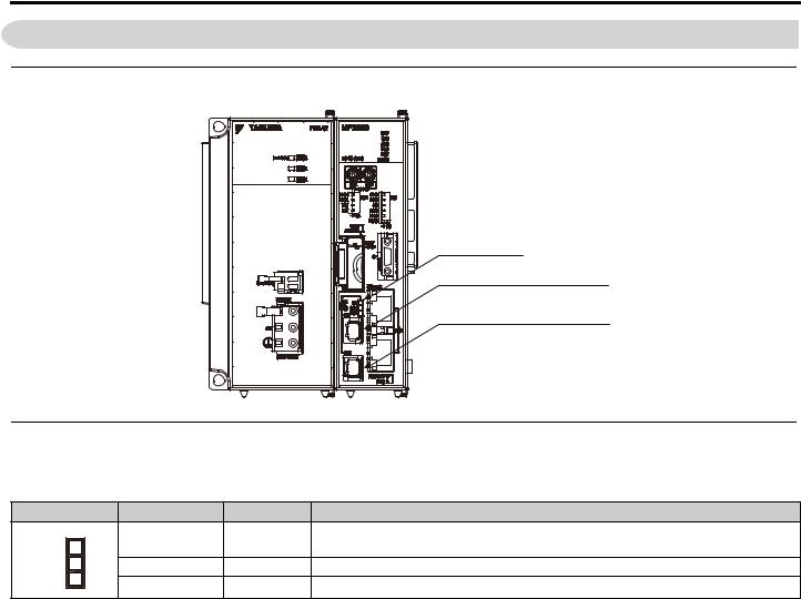
Connectors
The Power Supply Unit has three connectors: RLYOUT, power supply, and Unit connectors.
RLYOUT Connector
This connector outputs the operating status of the CPU Unit.
Model: 734-302
Pin Assignments
No. |
Signal Label |
Description |
1 |
OUT |
Normal operation: Circuit closed. |
2 |
OUT |
Error: Circuit open. |
Power Connector
Connect the power supply to this connector.
AC Power Supply Unit |
DC Power Supply Unit |
|||||||||||||||||||||||||||||||||||
|
|
|
|
|
|
|
|
|
|
|
|
|
|
|
|
|
|
|
|
|
|
|
|
|
|
|
|
|
|
|
|
|
|
|
|
|
|
|
|
|
|
|
|
|
|
|
|
|
|
|
|
|
|
|
|
|
|
|
|
|
|
|
|
|
|
|
|
|
|
|
|
|
|
|
|
|
|
|
|
|
|
|
|
|
|
|
|
|
|
|
|
|
|
|
|
|
|
|
|
|
|
|
|
|
|
|
|
|
|
|
|
|
|
|
|
|
|
|
|
|
|
|
|
|
|
|
|
|
|
|
|
|
|
|
|
|
|
|
|
|
|
|
|
|
|
|
|
|
|
|
|
|
|
|
|
|
|
|
|
|
|
|
|
|
|
|
|
|
|
|
|
|
|
|
|
|
|
|
|
|
|
|
|
|
|
|
|
|
|
|
|
|
|
|
|
|
|
|
|
|
|
|
|
|
|
|
|
|
|
|
|
|
|
|
|
|
|
|
|
|
|
|
|
|
|
|
|
|
|
|
|
|
|
|
|
|
|
|
|
|
|
|
|
|
|
|
|
|
|
|
|
|
|
|
|
|
|
|
|
|
|
|
|
|
|
|
|
|
|
|
|
|
|
|
|
|
|
|
|
|
|
|
|
|
|
|
|
|
|
|
|
|
|
|
|
|
Type |
Model |
|
Color |
|
AC Power Supply Unit |
721-203/026-304 |
|
Black |
||
DC Power Supply Unit |
721-203/026-000 |
|
White |
||
Pin Assignments: AC Power Supply Unit |
|
|
|
||
|
|
|
|
|
|
Pin No. |
|
Signal Label |
Description |
|
|
3 |
|
AC |
AC input |
|
|
2 |
|
AC |
AC input |
|
|
1 |
|
FG |
Connects to the frame ground. (Ground to 100 W max.) |
||
Pin Assignments: DC Power Supply Unit |
|
|
|
||
|
|
|
|
|
|
Pin No. |
|
Signal Label |
Description |
|
|
3 |
|
24 VDC |
Power input wire for 24 VDC |
|
|
2 |
|
0 VDC |
Power input wire for 0 VDC |
|
|
1 |
|
FG |
Connects to the frame ground. (Ground to 100 W max.) |
||
YASKAWA America, Inc. MP3200iec Hardware Manual YAI-SIA-IEC-5 |
9 |

5 Power Supply Unit Specifications
5 Power Supply Unit Specifications
The specifications of the Power Supply Unit are given in the following table.
|
Item |
|
|
Specification |
|||
|
|
AC Power Supply Unit |
|
|
DC Power Supply Unit |
||
|
|
|
|
|
|||
Model |
|
JEPMC-PSA3012-E |
|
|
JEPMC-PSD3012-E |
||
Abbreviation |
|
PSA-12 |
|
|
PSD-12 |
||
|
Input Voltage |
100/200 VAC |
|
|
24 VDC |
||
|
Allowable Input Voltage |
85 to 132 VAC or 170 to 276 VAC |
|
19.2 to 28.8 VDC |
|||
|
Range |
|
|||||
|
|
|
|
|
|
|
|
|
Allowable Frequency |
47 to 63 Hz |
|
- |
|
||
|
Range |
|
|
||||
|
|
|
|
|
|
|
|
|
Input Current |
4.0 A max. (at rated input/output) |
|
5.0 A max. (at rated input/output) |
|||
|
|
25 A, 10 ms max. (fully discharged, 132-VAC |
|
|
|
||
Power Supply |
Inrush Current |
input, rated output) |
|
|
50 A, 10 ms max. (fully discharged, |
||
50 A, 10 ms max. (fully discharged, 276-VAC |
|
28.8-VDC input, rated output) |
|||||
Section |
|
|
|||||
|
input, rated output) |
|
|
|
|
||
|
|
|
|
|
|
||
|
Allowable Momentary |
20 ms |
|
|
1 ms |
||
|
Power Loss Time |
|
|
||||
|
|
|
|
|
|
|
|
|
Rated Voltage |
5.15 V |
|
|
|
|
|
|
Rated Current |
12.0 A |
|
|
|
|
|
|
Output Current Range |
0 to 12.0 A |
|
|
0.2 to 12.0 A |
||
|
Constant Voltage |
5.15 V ±2% max. (5.05 to 5.25 V) |
|
|
|
||
|
Accuracy |
|
|
|
|||
|
|
|
|
|
|
|
|
|
|
If the Power Supply Unit is mounted on the Main Rack, this output functions as normally closed |
|||||
|
|
contacts that are synchronized with the status of the CPU Unit. |
|||||
|
|
• Normal operation: Circuit closed. |
|
|
|
||
|
|
• Error: Circuit open. |
|
|
|
|
|
|
|
Contact Ratings |
|
|
|
|
|
Status Output |
|
|
|
|
|
|
|
|
|
Input Voltage |
Current Capacity |
|
|||
|
|
|
|
||||
|
|
|
24 VDC |
0.5 A (resistive load) |
|
||
|
|
|
0.25 A (inductive load) |
|
|||
|
|
|
|
|
|||
|
|
|
|
|
|
||
|
|
|
125 VAC |
0.4 A (resistive load) |
|
||
|
|
|
|
|
|
|
|
|
|
|
0.2 A (inductive load) |
|
|||
|
|
|
|
|
|||
|
|
|
|
|
|
|
|
Connectors |
|
POWER: Power supply connector |
|
|
|
||
|
RLY OUT: Relay contact connector |
|
|
|
|||
|
|
|
|
|
|||
Indicators |
|
POWER |
|
|
|
|
|
|
Refer to Indicators on page 12. |
|
|
|
|||
|
|
|
|
|
|||
|
|
|
|
|
|
For Cold Start |
|
|
|
For Cold Start |
|
|
(Through rate at input voltage value increase from |
||
|
Inrush Current |
50 A within 10 ms (fully discharged status) |
|
10% to 90% is at 10 ms min.) |
|||
|
|
275-VAC input, rated output |
|
50 A within 10 ms (fully discharged status) |
|||
|
|
|
|
|
|
28.8-VDC input, rated output |
|
|
Rise Time |
60,000 ms max. (The maximum time for the output control signals to maintain the specified timing |
|||||
Input Conditions |
when the primary voltage rises linearly.) |
|
|
|
|||
|
|
|
|
||||
|
Drop Time |
60,000 ms max. (The maximum time that the controls, such as the power failure sequence, can be |
|||||
|
maintained when the primary voltage drops linearly.) |
||||||
|
|
||||||
|
Leakage Current |
276 VAC 61 Hz: 0.5 mA max. |
- |
|
|||
|
132 VAC 61 Hz: 0.25 mA max. |
|
|||||
|
|
|
|
|
|||
|
Efficiency |
70% minimum (for rated input voltage and |
|
65% minimum (for rated input voltage and rated |
|||
|
rated load) |
|
|
load) |
|||
|
|
|
|
||||
10 |
YASKAWA America, Inc. MP3200iec Hardware Manual YAI-SIA-IEC-5 |
|
|
|
|
|
|
|
|
5 Power Supply Unit Specifications |
||
|
|
|
|
|
|
|
|
|
|
|
|
Item |
|
|
|
|
|
Specification |
|||
|
|
AC Power Supply Unit |
DC Power Supply Unit |
|||||||
|
|
|
||||||||
|
Low Input Protection |
|
|
|
|
|
|
|
|
|
|
(Power Fail Detection |
55 to 75 VAC or 150 VAC max. |
|
|
|
15.8 to 17.8 VDC |
||||
|
Level) |
|
|
|
|
|
|
|
|
|
|
Overcurrent Protection |
For rated current (12 A), the protection operates |
at 14.0 A min. (typical). |
|||||||
Protection |
(The detection range is 13.0 to 15.0 A.) |
|
|
|||||||
|
|
|
||||||||
|
Overvoltage Protection |
Operates at 5.75 to 6.75 V. |
|
|
|
|
|
|||
|
Allowable Power Loss |
The output voltage fluctuation range is |
The output voltage fluctuation range is maintained |
|||||||
|
maintained for a 20-ms 100% dip momentary |
|||||||||
|
Time |
for a 1-ms 100% dip momentary power loss. |
||||||||
|
power loss. |
|
|
|
||||||
|
|
|
|
|
|
|
||||
Safety |
Safety Standards |
Conforms to UL and CSA. |
|
|
|
|
|
|||
Fuse |
250 V/4 A |
|
|
|
250 V/6.3 A |
|||||
|
|
|
|
|||||||
|
|
Linked to the RDY indicator on the CPU Unit. |
|
|
||||||
|
|
RDY indicator lit: Circuit closed. |
|
|
|
|
|
|||
|
|
RDY indicator not lit: Circuit open. |
|
|
|
|
||||
|
|
Contact Ratings |
|
|
|
|
|
|||
Status |
NO Contact Output (RLY |
|
|
|
|
|
|
|
|
|
|
Input Voltage |
|
|
|
Current Capacity |
|
||||
Output |
OUT) |
|
|
|
|
|
||||
|
|
|
24 VDC |
|
|
|
0.5 A (resistive load) |
|
||
|
|
|
|
0.25 A (inductive load) |
|
|||||
|
|
|
|
|
|
|||||
|
|
|
125 VAC |
|
|
|
0.4 A (resistive load) |
|
||
|
|
|
|
|
0.2 A (inductive load) |
|
||||
|
|
|
|
|
|
|
||||
|
|
|
|
|
|
|
|
|
|
|
|
Power ON |
AC ON - 5-V rise in 1 s max. |
|
|
|
DC ON - 5-V rise in 1 s max. |
||||
|
Output rise - POK signal in 0 s min. |
|
Output rise - POK signal in 0 s min. |
|||||||
Power Sequences |
|
|
||||||||
Power OFF |
AC OFF - POK signal for 20 ms min. |
DC OFF - POK signal for 1 ms min. |
||||||||
|
||||||||||
|
POK signal - 5-V drop in 2 ms min. |
|
|
POK signal - 5-V drop in 2 ms min. |
||||||
|
|
|
|
|||||||
|
Between primary and secondary sides: 1,500 VAC for 1 minute |
|
|
|
||||||
Dielectric |
Between primary side and FG (ground): 1,500 VAC for 1 minute |
|
|
|||||||
Between secondary side and FG (ground): 500 VAC for 1 minute |
|
|
||||||||
Strength |
|
|
||||||||
Between RLYOUT and primary side: 1,500 VAC for 1 minute |
|
|
|
|
|
|||||
|
|
|
|
|
|
|||||
|
Between RLYOUT and secondary side: 1,500 VAC for 1 minute |
|
|
|||||||
Insulation |
Between primary and secondary sides: 10 MΩ min. |
|
|
|
|
|
||||
Between primary side and FG (ground): 10 MΩ min. |
|
|
|
|
|
|||||
Resistance |
|
|
|
|
|
|||||
Between secondary side and FG (ground): 100 MΩ min. |
|
|
|
|
|
|||||
(Measured at |
|
|
|
|
|
|||||
Between RLYOUT and primary side: 100 MΩ min. |
|
|
|
|
|
|||||
500 VDC.) |
|
|
|
|
|
|||||
Between RLYOUT and secondary side: 100 MΩ min. |
|
|
|
|
|
|||||
|
|
|
|
|
|
|||||
|
External Power Supply |
AC, AC |
|
|
|
0 and 24 VDC |
||||
External Wiring |
Terminals |
|
|
|
||||||
|
|
|
|
|
|
|
|
|||
Connector |
Protective Ground |
FG |
|
|
|
|
|
|||
Terminals |
Terminal |
|
|
|
|
|
||||
|
|
|
|
|
|
|
|
|||
|
RLY OUT |
RLYOUT |
|
|
|
|
|
|||
|
External Power Supply |
AWG28 to AWG13 (0.08 to 2.6 mm2) |
|
|
||||||
Connector Cable |
Terminals (Twisted Pair) |
|
|
|||||||
|
RLY OUT Connector Cable: AWG28 to AWG14 (0.08 to 2.0 mm2) |
|
|
|||||||
Hot |
Not supported. |
|
|
|
|
|
|
|
|
|
Swapping |
|
|
|
|
|
|
|
|
||
|
|
|
|
|
|
|
|
|
||
YASKAWA America, Inc. MP3200iec Hardware Manual YAI-SIA-IEC-5 |
11 |

5 Power Supply Unit Specifications
Item |
|
Specification |
|
|
|
AC Power Supply Unit |
|
DC Power Supply Unit |
|
|
|
|
||
POWER |
(green): Lights when the power is ON on the secondary side. |
|
||
(No label) |
(yellow): Lights when the Overcurrent Warning 1 Status Output is ON. |
|||
(No label) |
(red): Lights when the Overcurrent Warning 2 Status Output is ON. |
|
||
Indicators |
|
Output Current (iout (typical)) |
POWER (Green) |
(No Label) (Yellow) |
(No Label) (Red) |
|
|
|
i out ≤ 8.9 A |
z |
{ |
{ |
|
|
|
9.0 A ≤ iout ≤ 11.4 A |
z |
z |
{ |
|
|
|
11.5 A ≤ iout ≤ 13.9 A |
z |
z |
z |
|
|
|
14.0 A ≤ iout (OCP activation) |
{ |
{ |
{ |
|
|
|
z: Lit {: Not lit. |
|
|
|
|
External |
Width: 60 mm, Height: 130 mm, Depth: 137 mm |
|
|
|
||
Dimensions |
|
|
|
|||
|
|
|
|
|
|
|
Weight |
350 g |
|
|
|
|
|
12 |
YASKAWA America, Inc. MP3200iec Hardware Manual YAI-SIA-IEC-5 |

6 CPU Specifications
6 CPU Specifications
The hardware specifications of the CPU Unit are given in the following table.
Item |
Specification |
|
Model |
PMC-U-MP320xx |
|
Abbreviation |
MP3200iec |
|
Flash Memory |
Capacity: 40 MB (32 MB of user memory) |
|
SDRAM |
Capacity: 128 MB |
|
SRAM |
Capacity: 8 MB (battery backup) |
|
Calendar |
Seconds, minutes, hour, day, week, month, year, day of week, and timing (battery backup) |
|
Ethernet |
10Base-T or 100Base-TX x 2 ports (hub) |
|
MECHATROLINK |
MECHATROLINK-III: 1 circuit with 2 ports |
|
USB |
USB 2.0 Type A host, 1 port |
|
Compatible devices: USB storage |
||
|
||
|
Seven-segment display |
|
|
Status indicators |
|
Indicators and Displays |
USB status indicator |
|
|
MECHATROLINK-III status indicators |
|
|
Ethernet status indicators |
|
|
DIP switch: Mode switch 1 |
|
Switches |
DIP switch: Mode switch 2 |
|
Rotary switches |
||
|
||
|
STOP/SAVE switch. Refer to DIP Switch Settings on page 27 for detailed switch information. |
CPU Communications Specifications
The specifications of the Communications Protocols built into the CPU Unit are given in the following table.
Protocol |
Mode |
Detail |
|
Modbus TCP |
MP3200iec as Master (Client) |
Maximum Number of Data Blocks = 20 |
|
MP3200iec as Slave (Server) |
1000 registers in, 1000 registers out, 256 coils in, 256 coils out |
||
|
|||
|
MP3200iec as Master (Scanner) |
Maximum Number of Data Blocks = 100 |
|
Ethernet/IP |
MP3200iec as Slave (Adapter) |
Total 16 instances in, 16 instances out, arranged as 3 instances of 256 |
|
|
bytes, 3 instances of 128 bytes, and 10 instances of 496 bytes. |
||
|
|
||
OPC |
read/write |
Any Global variable can be configured, requires OPC Server running |
|
on PC |
|||
|
|
||
Custom Protocol |
n/a |
Use the YDeviceComm firmware library to create a custom |
|
communication protocol. |
|||
|
|
YASKAWA America, Inc. MP3200iec Hardware Manual YAI-SIA-IEC-5 |
13 |
7 CPU External Appearance and Indicators
7CPU External Appearance and Indicators
External Appearance
Indicators (LEDs)
MECHATROLINK-III connector CN1
MECHATROLINK-III connector CN2
Indicators
The following table describes the indicators that show the operating status and error information.
Indicator |
Indicator Name |
Color |
Meaning When Lit |
|
|
CN |
Green |
MECHATROLINK-III communications are established as a slave (i.e., the CONNECT |
|
CN |
command is ON). |
|||
|
|
|||
LK1 |
LK1 |
Green |
Port 1 is performing MECHATROLINK-III communications. |
|
LK2 |
LK2 |
Green |
Port 2 is performing MECHATROLINK-III communications. |
|
|
14 |
YASKAWA America, Inc. MP3200iec Hardware Manual YAI-SIA-IEC-5 |

8 Base Unit Installation and Operating Conditions
8 Base Unit Installation and Operating Conditions
This section describes the specifications of the MP3200iec Series Machine Controllers.
Install the MP3200iec Series Controllers in an environment with the following conditions.
Environmental Conditions
Item |
Specification |
Ambient Operating Temperature |
0 to 55°C (CPU-03: 0 to 50°C) |
Ambient Storage Temperature |
-25 to 85°C |
Ambient Operating Humidity |
30% to 95% RH (with no condensation) |
Ambient Storage Humidity |
5% to 95% RH (with no condensation) |
Pollution Degree |
Conforms to JIS B 3502 Pollution Degree 2. |
Corrosive Gases |
There must be no combustible or corrosive gases. |
Operating Altitude |
2,000 m max. |
Control Panel Cooling Method
The components that are used in the Machine Controller require the ambient operating temperature to be between 0 and 55°C. Use one of the methods described below to ensure adequate cooling in the control panel.
Note: If the ambient temperature exceeds 50°C, we recommend forced-air cooling.
Control Panels with Natural Cooling
•Do not mount the Machine Controller at the top of the control panel, where the hot air that is generated inside the panel collects.
•Leave sufficient space above and below the Units, and maintain adequate distances from other devices, cable ducts, and other objects to ensure suitable air circulation.
•Do not mount the Controller in any direction other than the specified direction.
•Do not mount the Controller on top of any device that generates a significant amount of heat.
•Do not subject the Controller to direct sunlight.
Control Panels with Forced-air Cooling
Use one of the following methods to ensure 0.03 m3/min average airflow below the CPU Unit.
•Forced draft method (A fan or a similar device is used to circulate the air in the interior and the exterior of the panel.)
•Forced circulation method (A fan or a similar device is mounted to the airtight panel to circulate the air inside.)
Note: Use the following guideline when selecting the fan: CPU Unit’s resistance to air flow: 6 x 10⁶ (N×s2/m8)
YASKAWA America, Inc. MP3200iec Hardware Manual YAI-SIA-IEC-5 |
15 |
8 Base Unit Installation and Operating Conditions
Fan |
|
CPU Unit’s internal resistance to |
|
air flow: 6 106 (N s2/m8) |
40 mm min. |
30 mm min. |
30 mm min. |
Average airflow: |
40 mm min. |
0.03 m3/min |
|
Mechanical Operating Conditions
Item |
|
Specification |
|
|
Conforms to JIS B 3502. |
||
Vibration Resistance |
10 |
Hz ≤ f < 57 Hz with vibration amplitude of 0.075 mm |
|
57 |
Hz ≤ f ≤ 150 Hz with fixed acceleration of 9.8 m/s2 |
||
|
|||
|
10 sweeps each in X, Y, Z directions (sweep: 1 octave/min) |
||
Shock Resistance |
Conforms to JIS B 3502. |
||
Peak acceleration of 147 m/s2 twice for 11 ms each in the X, Y, and Z directions |
|||
|
|||
Electrical Operating Conditions
Item |
Specification |
Conforms to EN 61000-6-2 and EN 55011 (Group 1 Class A).
Power supply noise (FT noise): 2 kV min. for 1 minute
Noise Resistance Radiation noise (FT noise): 1 kV min., for 1 minute
Ground noise (impulse noise): ±1 kV min., for 10 minutes
Electrostatic noise (conducted): ±4 kV min., 10 times
Ground Information |
Ground to 100 ȍ max. |
16 |
YASKAWA America, Inc. MP3200iec Hardware Manual YAI-SIA-IEC-5 |
9 Installation
9 Installation
You can use either of the following methods to install an MP3200iec Series Controller.
•Screw mounting
•DIN rail mounting
Screw Mounting
You can install the Unit by using the Screw Mounting Attachment.
Note: You can install the Unit by using the Screw Mounting Attachment.
•JEPMC-OP3001
This Attachment is provided with the Power Supply Unit. It can be installed on the PMC-U-MP320**.
•JEPMC-OP3002
This Attachment is provided with the MBU-B03, MBU-B05, and MBU-B08. It can be purchased separately.
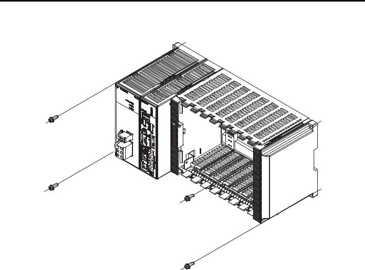
The installation procedure is as follows:
1. Attach the Screw Mounting Attachment to the right end of the Controller.
Screw Mounting Attachment
YASKAWA America, Inc. MP3200iec Hardware Manual YAI-SIA-IEC-5 |
17 |
9 Installation
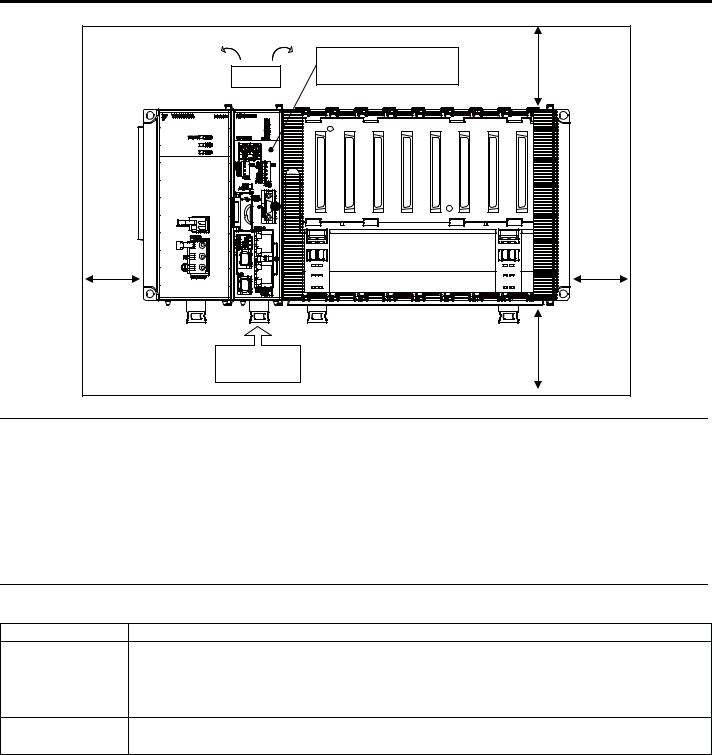
2. Use screws to secure the 4 places shown in the following figure.
Note: 1. Recommended screws: M4 x 14 mm min.
2. Use a screwdriver with a shaft that is at least 13 cm long.
18 |
YASKAWA America, Inc. MP3200iec Hardware Manual YAI-SIA-IEC-5 |
9 Installation
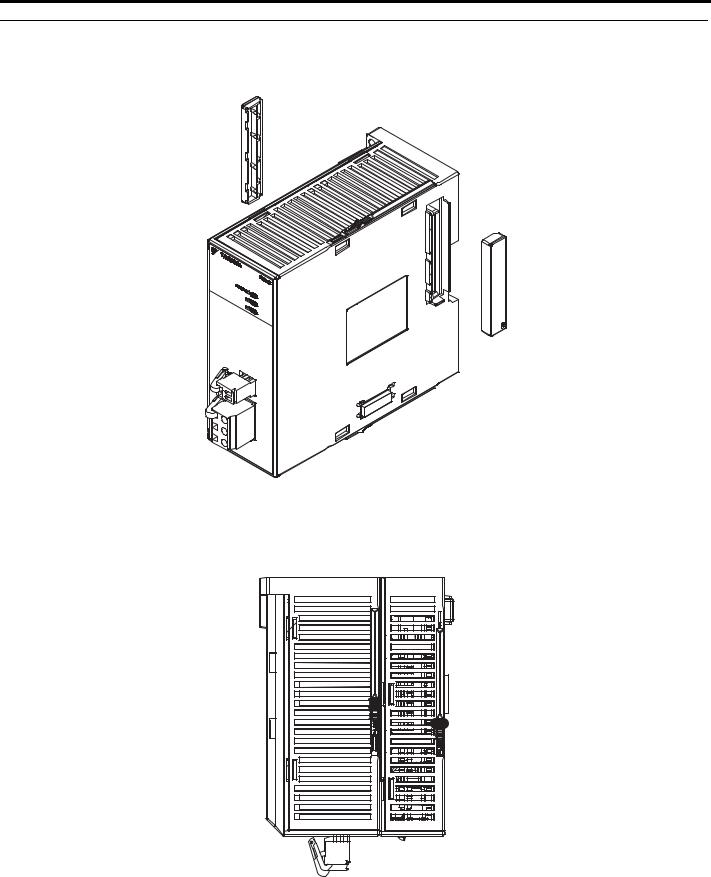
DIN Rail Mounting
Carefully line up the DIN rail locks with the locking positions.
Locking position
Lock release position
Note: Removal
You can remove the Controller by reversing the order of the mounting procedure.
YASKAWA America, Inc. MP3200iec Hardware Manual YAI-SIA-IEC-5 |
19 |
9Installation
Connecting the CPU
Note: Before you connect the CPU, install the Battery. Refer to Installing and Replacing the Battery in the CPU on page 24.
1. Remove the rubber cap from the connector on the Power Supply Unit.
Note:
•When the connector is not in use, always cover it with the rubber cap.
•The left-side cap is marked with an L, and the right-side cap is marked with an R.
2.Connect the Power Supply Unit and the CPU Unit from left to right in this order.
20 |
YASKAWA America, Inc. MP3200iec Hardware Manual YAI-SIA-IEC-5 |
9 Installation
3. Secure the connection by locking the slide locks at both the top and the bottom.
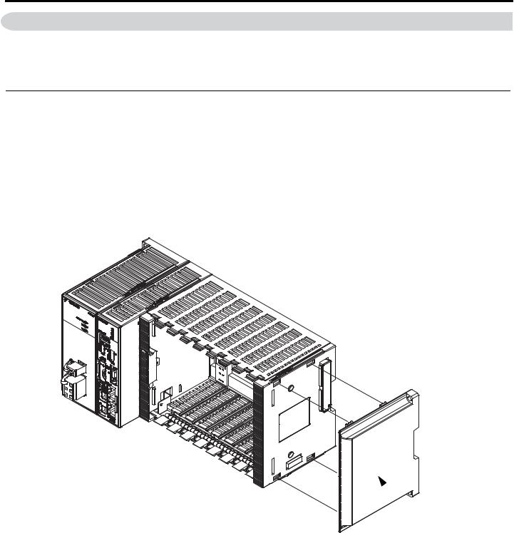
Installing Optional Modules
Use the following procedure to install Optional Modules.
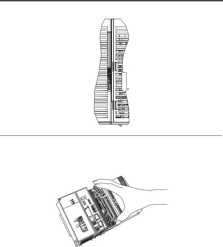
1. Hold the top and bottom of the Optional Module to be installed, line up the Module with the left side of the guide rail inside the option slot, and then insert the Module straight in.
Note: The FG bar inside and on the bottom may be damaged if the Module is not inserted along the guide rail.
|
|
# |
|
#9 |
|
5- |
|
|
;# |
|
|
|
|
4&; |
|
|
|
|
|
|
|
.& |
||
|
|
|
|
|
|
|
|
|
|
|||
|
|
470 |
|
|
|
|
|
|
|
.& |
||
|
2 |
|
#./ |
|
|
|
|
|
|
|
|
|
|
/ |
|
|
'44 |
|
|
|
|
|
|
|
|
|
|
|
|
$#6 |
|
|
|
|
|
|
|
|
# |
|
|
./ |
|
|
|
|
|
|
|
||
25 |
|
|
|
/# |
|
|
|
|
|
|
|
|
|
|
|
|
|
|
|
|
|
|
|
+1 |
|
|
7 |
|
|
|
|
|
|
|
|
|
|
|
|
%2 |
|
|
|
|
|
|
|
|
|
|
|
|
|
|
|
# |
|
|
|
|
|
|
|
|
|
|
|
|
|
|
|
|
|
|
|
|
|
|
|
# |
|
|
|
|
59 |
|
|
|
||
|
|
|
|
: |
|
|
|
|
|
|
||
|
|
#&&4 |
5612 |
|
|
|
|
|
|
|||
|
|
: |
|
|
|
|
|
|
||||
219'4 |
|
+2 |
|
|
+6 |
|
|
|
|
|
|
|
|
|
|
59 |
'+0+6 |
|
|
|
|
|
|||
|
|
/ |
|
|
|
+0 |
|
|
|
|
|
|
|
'2 |
|
|
|
0() |
|
|
|
|
|
||
|
|
' 2/56 |
|
|
|
% |
& |
|
|
|
|
|
|
|
|
|
|
.1# |
6 |
10 |
|
|
|
||
|
|
6' |
|
10 |
|
45 |
|
|
|
|||
|
|
/06 |
|
& |
|
|
|
|
|
|||
|
|
|
|
75$ |
|
|
|
|
|
|
|
|
|
|
|
|
+8' |
|
|
12 |
|
|
|
||
|
|
|
|
#%6 |
|
|
|
|
|
|||
|
|
|
|
|
|
|
|
56 |
8' |
|
|
|
|
|
|
|
|
|
|
|
5# |
|
|
|
|
|
|
|
|
|
|
|
|
|
12 |
|
|
|
|
|
|
|
|
|
|
|
|
|
TPGV |
|
|
|
|
|
|
|
|
|
|
|
|
'VJG |
|
|
|
|
|
|
|
|
|
|
|
|
%0 |
|
|
|
|
|
|
|
|
|
|
|
++.- |
*7$ |
|
|
|
|
|
|
|
|
|
|
|
/+ |
.- |
|
|
|
|
|
|
|
|
|
|
|
%0 |
|
|
|
|
76 |
|
|
|
|
|
|
|
|
|
|
|
|
4.;1 |
|
|
|
|
|
|
|
|
|
|
|
|
|
|
|
|
|
|
|
|
|
%0 |
|
|
|
|
|
|
|
|
|
|
|
|
|
|
#%6 |
|
|
|
|
|
|
|
|
|
|
|
0- |
/ |
|
|
|
|
|
|
|
|
|
|
|
%.+ |
|
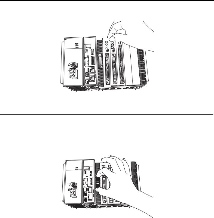
2.After the Optional Module is completely inserted, place your hand on the front of the Optional Module and press the Optional Module firmly until it mates with the Mounting Base connectors in the Unit. The front of the Optional Module and the tabs will be aligned if the Optional Module has been installed properly.
YASKAWA America, Inc. MP3200iec Hardware Manual YAI-SIA-IEC-5 |
21 |
9 Installation
3.Place the hole on the bottom of the panel of the Optional Module onto the tab on the bottom of the Unit. Next, hook the hole at the top of the panel of the Optional Module onto the tab on the Unit.
;#5-#9# |
25# |
|
219'4 |
8 8
/2 |
|
4&; |
|
|
|
|
|
|
|
|
|
|
470 |
|
|
|
|
#./ |
|
|
|
|
'44 |
|
|
|
|
$#6 |
|
%27 |
|
/ #./ |
|
|
|
|
|
|
|
|
|
|
||
|
|
|
|
|
|
# |
& |
# |
|
|
& |
|
|
|
: |
: |
|
||
|
+2 #&&4 |
|
|
|
' 2/ |
|
59 |
5612 |
59 |
' 2/ |
|
' +0+6 |
|
|
6'56 |
|
|
+0+6 |
|
/06 |
|
|
%0() |
|
|
10 |
|
.1#& |
|
|
|
|
& 456 |
|
|
75$ |
|
|
10 |
#%6+8' |
|
|
|
|
|
|
5612 |
|
|
|
|
5#8' |
|
|
|
|
|
12 |
|
|
|
'VJGTPGV |
|
|
|
%0 |
|
|
|
|
.- |
|
|
|
%0 .- |
|
|
|
|
|
|
|
|
*7$ |
%0 |
|
|
|
|
.+1 |
|
|
|
|
|
.& |
.& |
|
|
|
|
.& |
.& .& |
.& |
470 |
( |
|
|
|
|
|||
|
|
.& |
.& |
%0 |
|
.& |
.& |
|
|
||
|
|
|
|
||
|
.& |
.& |
.& |
|
|
.& |
|
.& |
|
|
|
|
|
.& |
|
|
|
|
|
/1&' |
|
|
|
+
%0
This completes the installation procedure.
Note: Always use Option Covers (model: JEPMC-OP2300) to cover unused slots.
Replacing and Adding Optional Modules
Use the following procedure to replace or add Optional Modules.
Note: Always create a backup before replacing or adding Optional Modules.
Use the Web Server to save the Application program image as an Archive.Zip.
1.Turn OFF the power supply and disconnect all cables from the MP3200iec.
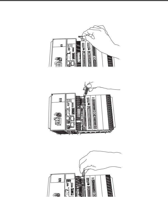
2.Remove the tool from Base Unit.
;#5-#9# |
25# |
219'4 

/2 |
|
|
4&; |
||
|
|
|
|
|
470 |
|
|
|
|
|
#./ |
|
|
|
|
|
'44 |
|
|
|
|
|
$#6 |
%27 |
|
|
|
/ #./ |
|
|
|
|
|
|
|
|
|
|
|
|
|
|
|
|
|
|
|
|
& |
|
& |
|
|
: |
: |
|
|||
|
+2 #&&4 |
|
|
|
|
' 2/ |
|
59 |
|
5612 |
59 |
' 2/ |
|
|
' +0+6 |
|
|
6'56 |
|
|
|
+0+6 |
|
/06 |
|
|
|
%0() |
|
|
10 |
|
|
.1#& |
|
|
|
|
& 456 |
|
|
75$ |
|
|
|
10 |
|
#%6+8' |
|
|
|
|
|
|
|
5612 |
|
||
|
|
5#8' |
|
||
|
|
|
|
12 |
|
'VJGTPGV
%0
.- %0 .-
.+1 |
.+1 |
|
.& |
.& |
.& |
.& |
.& |
.& |
.& |
|
.& |
|
|
.& |
*7$
%0
8 8
%0
22 |
YASKAWA America, Inc. MP3200iec Hardware Manual YAI-SIA-IEC-5 |
9 Installation
3.Insert the protruding part of the tool into the slot on top of the Optional Module panel to unhook the tab. Unhook the bottom tab in the same way.
NOTICE: Use the same method to remove the Option Cover from an unused slot before adding an Optional Module.
;#5-#9# |
25# |
219'4 

4.;1 


/2 |
|
4&; |
|
|||
|
|
|
|
|
||
|
|
|
|
470 |
|
|
|
|
|
|
#./ |
|
|
|
|
|
|
'44 |
|
|
|
|
|
|
$#6 |
|
|
%27 |
|
/ #./ |
|
|||
|
|
|
|
|
||
|
|
|
|
|
|
|
|
% |
|
% |
|
|
|
|
|
: |
|
|
||
: |
|
|
|
|||
|
+2 #&&4 |
|
|
|
||
' 2/ |
|
|
59 |
5612 |
|
59 |
' 2/ |
|
|
' +0+6 |
|
|
|
6'56 |
|
|
|
+0+6 |
|
|
/06 |
|
|
|
%0() |
|
|
|
|
10 |
|
.1#& |
|
|
|
|
|
& 456 |
|
|
|
75$ |
10 |
#%6+8' |
|
|
5612 |
|
5#8' |
|
12 |
'VJGTPGV
|
%0 |
/ +++ .- |
|
%0 |
.- |
.+1 |
.+1 |
|
|
.& |
.& |
.& |
.& |
.& |
.& |
.& |
.& |
.& |
.& |
.& |
.& |
.& |
.& |
.& |
.& |
/1&' |
|
/1&' |
|
|
+ 1 |
|
+ 1 |
4.Pull the top of the Optional Module panel toward you and remove it. A notch on the Optional Module will be visible from the gap of the panel. Hook the round knob on the tool into the notch in the Optional Module.
;#5-#9# |
25# |
|
219'4 |
/2 |
|
|
4&; |
||
|
|
|
|
|
470 |
|
|
|
|
|
#./ |
|
|
|
|
|
'44 |
|
|
|
|
|
$#6 |
%27 |
|
|
|
/ #./ |
|
|
|
|
|
|
|
|
|
|
|
|
|
|
# |
|
& |
# |
|
& |
|
|
|
|
|
: |
: |
|
|||
+2 #&&4 |
|
|
|
||
' 2/ |
|
59 |
|
5612 |
59 |
' 2/ |
|
|
' +0+6 |
|
|
6'56 |
|
|
|
+0+6 |
|
/06 |
|
|
|
%0() |
|
|
10 |
|
|
.1#& |
|
|
|
|
& 456 |
|
|
75$ |
|
|
|
10 |
|
#%6+8' |
|
|
|
|
|
|
|
5612 |
|
||
|
|
5#8' |
|
||
|
|
|
|
12 |
|
.+1 |
.+1 |
||
.& |
.& |
470 |
(7 |
|
|||
.& |
.& |
%0 |
|
|
|
||
.& |
.& |
|
|
.& |
.& |
|
|
/1&' |
|
|
|
|
+ 1 |
|
|
'VJGTPGV
%0
.- %0 .-
*7$ 
%0
8 8
%0
5.Hold the center of the tool, and turn it around the round knob while pushing it toward the back to disconnect the Module from the Mounting Base connectors. Then, pull the Module forward.
;#5-#9# |
25# |
|
|
219'4 |
|
|
|
0&;& |
|
/2 |
4&; |
|
||
|
|
|
470 |
|
|
|
|
#./ |
|
|
|
|
'44 |
|
%27 |
|
$#6 |
|
|
|
/ #./ |
|
||
|
: |
: |
|
|
|
+2 #&&4 |
|
|
|
' +0+6 |
59 |
5612 |
59 |
|
' +0+6 |
|
' +0+6 |
|
|
6'56 |
|
|
+0+6 |
|
/06 |
|
|
%0() |
|
|
10 |
|
.1#& |
|
|
|
|
& 456 |
|
|
75$ |
|
10 |
|
#%6+8' |
|
|
|
|
|
|
5612 |
|
|
|
|
5#8' |
|
|
|
|
|
1( |
|
.+1 |
.+1 |
||
.& |
.& |
470 |
(7 |
.& |
.& |
%0 |
|
.& |
.& |
|
|
.& |
.& |
|
|
/1&' |
|
|
|
+ 1 |
|
|
+ 1 |
YASKAWA America, Inc. MP3200iec Hardware Manual YAI-SIA-IEC-5 |
23 |
9 Installation
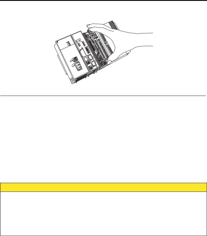
6.Hold the Optional Module at the top and bottom and pull it straight out. Hold the edges of the Module and avoid touching the components on the Module.
|
|
# |
|
#9 |
|
5- |
|
|
;# |
|
|
|
|
|
|
|
|
|
|
|
|
|
|
|
|
|
|
|
&; |
|
|
|
|
|
|
.& |
|
|
|
|
|
4 |
|
|
|
|
|
|
|
|
|
|
|
470 |
|
|
|
|
|
|
.& |
||
|
2 |
|
|
#./ |
|
|
|
|
|
|
|
|
|
/ |
|
|
|
'44 |
|
|
|
|
|
|
|
|
|
|
|
|
$#6 |
|
|
|
|
|
|
|
# |
|
|
|
./ |
|
|
|
|
|
|
||
25 |
|
|
|
|
/# |
|
|
|
|
|
|
|
|
|
|
|
|
|
|
|
|
|
|
+1 |
|
|
|
%27 |
|
|
|
|
|
|
|
|
|
|
|
|
|
|
|
|
|
|
|
|
|
|
|
|
|
|
|
|
|
|
|
|
|
|
|
|
|
|
|
|
|
|
59 |
|
|
|
|||
|
|
|
|
: |
|
|
|
|
||||
|
|
|
4 |
2 |
|
|
|
|
|
|||
|
|
|
: |
#&& |
561 |
|
|
|
|
|
||
9'4 |
|
|
+2 |
|
|
+6 |
|
|
|
|
||
|
|
|
|
59 +0 |
|
|
|
|
|
|||
21 |
|
2/ |
|
|
' |
0+6 |
|
|
|
|
||
|
|
|
|
|
+ |
) |
|
|
|
|
||
|
|
' |
|
|
|
|
%0( |
|
|
|
|
|
|
|
'2/56 |
|
|
|
.1#&6 |
10 |
|
|
|
||
|
|
|
6' |
|
|
10 |
|
45 |
|
|
|
|
|
|
|
/06 |
|
& |
|
|
|
|
|||
|
|
|
|
|
|
75$ |
|
|
|
|
|
|
|
|
|
|
|
|
+8' |
|
12 |
|
|
|
|
|
|
|
|
|
#%6 |
|
|
|
|
|||
|
|
|
|
|
|
|
|
56 |
8' |
|
|
|
|
|
|
|
|
|
|
|
5# |
|
|
|
|
|
|
|
|
|
|
|
|
|
12 |
|
|
|
|
|
|
|
|
|
|
|
|
|
TPGV |
|
|
|
|
|
|
|
|
|
|
|
|
'VJG |
|
|
|
|
|
|
|
|
|
|
|
|
%0 |
|
|
|
|
|
|
|
|
|
|
|
++.- |
*7$ |
|
|
|
|
|
|
|
|
|
|
|
/+ |
.- |
|
|
|
|
|
|
|
|
|
|
|
%0 |
|
|
|
|
76 |
|
|
|
|
|
|
|
|
|
|
|
|
4.;1 |
|
|
|
|
|
|
|
|
|
|
|
|
|
|
|
|
|
|
|
|
|
%0 |
|
|
|
|
|
|
|
|
|
|
|
|
|
|
#%6 |
|
|
|
|
|
|
|
|
|
|
|
0- |
/ |
|
|
|
|
|
|
|
|
|
|
|
%.+ |
|
Note: Put the Module that you removed into the bag that was supplied when you purchased it and store the Module in this bag.
Installing and Replacing the Battery in the CPU
Battery Installation
This Battery provides backup power for the SRAM data when the power supply to the MP3200iec Series CPU Unit is turned OFF. The Battery provides backup power for the following data.
•Alarm history
•Calendar
•Retain Variables
Note: One Battery is provided with the CPU Unit. The Battery is not connected when the Unit is delivered.
Battery Replacement
When the total power OFF time exceeds 1 year, the voltage of the Battery will drop, and the BAT indicator on the CPU Unit will light.
Replace the Battery within 2 weeks of when the BAT indicator first lights.
Battery Replacement Procedure
 CAUTION
•Allow only qualified personnel trained in safety procedures to replace the Battery. Incorrect Battery replacement may result in electric shock. Also, machine malfunction may occur, possibly resulting in injury or machine damage.
•Replace the Battery only while power is supplied to the Basic Unit. Replacing the Battery while the power supply to the Basic Unit is turned OFF may result in loss of the data stored in memory in the Unit.
•Do not touch the electrodes of the Battery. Static electricity may damage the electrodes.
•The Basic Module contains a lithium battery. When you replace the Battery, separate the used Battery from normal waste and dispose of it according to all local ordinances.
1.Back up the programs and data stored in the Basic Unit.
Note: The backup can be used to recover the data if the data accidentally gets deleted during Battery replacement.
2. Confirm that the RDY indicator on the CPU Unit is lit.
24 |
YASKAWA America, Inc. MP3200iec Hardware Manual YAI-SIA-IEC-5 |

9 Installation
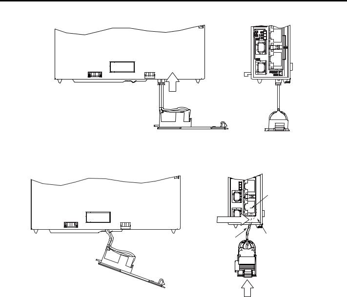
3. Open the battery holder on the bottom of the CPU Unit.
4.Disconnect the lead connector of the Battery from the connector on the CPU Unit, and remove the Battery from the battery holder.
 LiTHIUM
Red lead  Black lead
5.Insert the Replacement Battery into the battery holder, and securely connect the lead connector of the Battery to the connector of the CPU Unit.
Connector on CPU Unit
Battery lead connector
Battery
Battery holder
YASKAWA America, Inc. MP3200iec Hardware Manual YAI-SIA-IEC-5 |
25 |
9 Installation
6. Press the connector back into the CPU Unit.
Press in.
7. Hold the connector, and while pressing it toward the CPU Unit’s internal circuit board (the board on the side of the clamp), move the Battery and the battery holder into the CPU Unit.
Note: If this procedure is not followed, the battery leads may be pinched between the Battery and the circuit board, causing stress on the leads. If that occurs, the battery holder will bulge after step 8 of the procedure.
Clamp
Hold the connector and press in.
|
CPU Unit internal circuit board |
2 battery leads |
(on the side of the clamp) |
Move the Battery.
8.Close the battery holder and confirm that the BAT indicator on the CPU Unit is not lit. This completes Battery replacement.
26 |
YASKAWA America, Inc. MP3200iec Hardware Manual YAI-SIA-IEC-5 |

10 DIP Switch Settings
10 DIP Switch Settings
The DIP switch settings are only referenced when the power is initially turned ON with the exception of the STOP switch, which will immediately STOP IEC Application program execution.
SW1
|
|
|
STOP |
|
|
|
|
|
|
|
|
|
|
|
|
|
|
|
|
|
|
|
|
|
|
|
|
|
|
|
|
|
|
|
|
|
|
|
|
|
|
|
|
|
E_INIT |
|
|
|
|
|
|
|
|
SW |
|
|
|
|
|
|
|
|
|
|
|
|
|
||
|
|
|
INIT |
|
|
|
|
|
|
|
|
|
|
|
|
|
|
|
|
|
|
|
|
|
|
||
|
|
|
CNFG |
|
|
|
|
|
|
1 |
|
||
|
|
|
|
|
|
|
|
|
|
|
|
||
|
|
|
|
|
|
|
|
|
|
||||
|
|
|
LOAD |
|
|
|
|
|
|
|
|
|
|
|
|
|
|
|
|
|
|
|
|
|
|
|
|
|
|
|
D-RST |
|
|
|
|
|
NO |
|
|
|
|
|
|
|
|
|
|
|
|
|
|
|
|||
|
|
|
|
|
|
|
|
|
|
|
|
||
|
|
|
|
|
|
|
|
|
|
|
|
|
|
|
|
|
|
|
|
|
|
|
|
|
|
|
|
Switch |
Name |
Setting |
Operating Mode |
|
Default |
Details |
|||||||
S1-6 |
STOP |
ON |
User program stopped |
|
|
OFF |
Stops the user program execution. |
||||||
OFF |
User program running |
|
|
||||||||||
|
|
|
|
|
|
|
|
|
|
||||
|
|
ON |
Use default IP Address |
|
|
|
|
|
|
|
When ON, overrides Ethernet configuration according to |
||
S1-5 |
E_INIT |
|
Use IP Address set in the |
|
|
OFF |
|||||||
OFF |
|
|
Table A. |
||||||||||
|
|
Configuration |
|
|
|
|
|
|
|
||||
|
|
|
|
|
|
|
|
|
|
|
|||
|
|
ON |
For diagnostic |
|
|
|
|
|
|
|
The controller uses the fixed, default configuration. |
||
|
|
purposes only |
|
|
|
|
|
|
|
For diagnostics only. Turning this switch ON may help |
|||
S1-4 |
INIT |
|
|
|
OFF |
||||||||
OFF |
For diagnostic |
|
|
restore communications to the controller if the configuration |
|||||||||
|
|
|
|
|
|
|
|
|
|||||
|
|
purposes only |
|
|
|
|
|
|
|
is corrupted or invalid. |
|||
|
|
|
|
|
|
|
|
|
|
||||
S1-3 |
CNFG |
ON |
Self-configuration Mode |
|
|
OFF |
The controller creates Axes and I/O for all connected |
||||||
OFF |
Normal Operation |
|
|
devices. (Auto-configuration) |
|||||||||
|
|
|
|
|
|
|
|
|
|||||
S1-2 |
LOAD |
ON |
USB Mode |
|
|
OFF |
When ON, load either the user project or firmware from the |
||||||
OFF |
Internal FLASH Mode |
|
|
USB thumb drive. See Table B for details. |
|||||||||
|
|
|
|
|
|
|
|
|
|||||
S1-1 |
D-RST |
ON |
System Use |
|
|
OFF |
Not used. |
||||||
OFF |
Normal Operation |
|
|
||||||||||
|
|
|
|
|
|
|
|
|
|
||||
SW2
Sets the Ethernet port condition and other operating conditions.
The switch setting is read only when the module is first turned ON.
|
|
|
E-PM0 |
|
|
|
|
|
|
|
|
|
|
|
|
|
|
|
|
|
|
|
|
|
|
|
|
|
|
|
|
|
|
|
|
|
|
|
|
|
|
|
|
|
E-PM1 |
|
|
|
|
|
|
|
SW |
|
|
|
|
|
|
|
|
|
|
|
|
|
|||
|
|
|
|
|
|
|
|
|
|
|
|||
|
|
|
TEST |
|
|
|
|
|
2 |
|
|
||
|
|
|
|
|
|
|
|
|
|||||
|
|
|
|
|
|
|
|
|
|||||
|
|
|
MNT |
|
|
|
|
|
NO |
|
|
|
|
|
|
|
|
|
|
|
|
|
|
|
|||
|
|
|
|
|
|
|
|
|
|
|
|
|
|
|
|
|
|
|
|
|
|
|
|
|
|
|
|
Switch |
Switch Name |
State |
Operation Mode |
|
|
|
|
Default |
Description |
||||
|
|
ON |
Use Default IP Address according to |
|
When E-INIT is ON and E-PM0 is ON, |
||||||||
S2-4 |
E-PM0 |
|
OFF |
overrides Ethernet configuration according to |
|||||||||
|
|||||||||||||
OFF |
Table A |
|
|
|
|
||||||||
|
|
|
|
|
|
|
Table A. |
||||||
|
|
|
|
|
|
|
|
|
|
|
|
|
|
S2-3 |
E-PM1 |
ON |
Use Default IP Address according to |
|
When E-INIT is ON and E-PM1 is ON, |
||||||||
|
OFF |
overrides Ethernet configuration according to |
|||||||||||
OFF |
Table A |
|
|
|
|
||||||||
|
|
|
|
|
|
|
Table A. |
||||||
|
|
|
|
|
|
|
|
|
|
|
|
|
|
S2-2 |
TEST |
ON |
Display IP Address |
|
|
|
|
OFF |
When ON, the IP address is scrolled across the |
||||
OFF |
Normal Operation |
|
|
|
|
seven segment display. |
|||||||
|
|
|
|
|
|
|
|||||||
|
|
ON |
Maintenance Mode |
|
|
|
|
|
When ON, controller starts up in supervisor |
||||
|
|
|
|
|
|
|
|
|
|
|
|
|
mode. In this mode MECHATROLINK III, |
|
|
|
|
|
|
|
|
|
|
|
|
|
|
S2-1 |
MNT |
|
|
|
|
|
|
|
|
|
|
OFF |
PLC, Modbus/TCP and Ethernet/IP do not |
OFF |
Normal Operation |
|
|
|
|
start. The controller firmware can be updated, |
|||||||
|
|
|
|
|
|
|
|||||||
|
|
|
|
|
|
|
|
|
|
|
|
|
and clearing DOS FS alarms will repair the |
|
|
|
|
|
|
|
|
|
|
|
|
|
DOS FS. |
YASKAWA America, Inc. MP3200iec Hardware Manual YAI-SIA-IEC-5 |
27 |
 Loading...