


VS-616G5 Series (Revision F)
Programming Manual
Constant Torque Inverter with Adaptive Vector Control (AVC™)

! WARNING
PRECAUTIONS
1)Only turn ON the input power supply after replacing the front cover. Do not remove the cover while the inverter is powered up.
2)When the retry function (parameter L5-02) is selected, do not approach the inverter or the load, since it may restart suddenly after being stopped.
3)Since the Stop key can be disabled by a function setting, install a separate emergency stop switch.
4)Do not touch the heatsink or braking resistor, due to very high temperatures.
5)Since it is very easy to change operation speed from low to high speed, verify the safe working range of the motor and machine before operation.
6)Install a separate holding brake, if necessary.
7)Do not check signals during operation.
8)All inverter parameters have been preset at the factory. Do not change the settings unless required.
Failure to observe these precautions may result in equipment damage, serious personal injury or death.
NOTICE
Printed April 1999. The information contained within this document is the proprietary property of Yaskawa Electric America, Inc., and may not be copied, reproduced or transmitted to other parties without the expressed written authorization of Yaskawa Electric America, Inc.
No patent liability is assumed with respect to the use of the information contained herein. Moreover, because Yaskawa is constantly improving its high-quality products, the information contained in this manual is subject to change without notice. Every precaution has been taken in the preparation of this manual. Nevertheless, Yaskawa assumes no responsibility for errors or omissions. Neither is any liability assumed for damages resulting from the use of the information contained in this publication.
2 |
VS-616G5 Programming Manual |

Contents
Contents |
|
|
Section |
Description |
Page |
|
INTRODUCTION . . . . . . . . . . . . . . . . . . . . . . . . . . . . . . . . . . . . . . . . . . . . . . . . . . . . . . . . . . . . . |
. . . 5 |
|
VS-616G5 PARAMETER TREE . . . . . . . . . . . . . . . . . . . . . . . . . . . . . . . . . . . . . . . . . . . . . . . . . . |
. . 7 |
A |
INITIALIZATION PARAMETERS . . . . . . . . . . . . . . . . . . . . . . . . . . . . . . . . . . . . . . . . . . . . . . . . . . |
. . 9 |
A1 |
Initialization Set-up . . . . . . . . . . . . . . . . . . . . . . . . . . . . . . . . . . . . . . . . . . . . . . . . . . . . . . . . . |
. . 9 |
A2 |
User’s Parameters . . . . . . . . . . . . . . . . . . . . . . . . . . . . . . . . . . . . . . . . . . . . . . . . . . . . . . . . . . |
. 11 |
B |
APPLICATION PARAMETERS . . . . . . . . . . . . . . . . . . . . . . . . . . . . . . . . . . . . . . . . . . . . . . . . . . . . |
. 11 |
B1 |
Sequence . . . . . . . . . . . . . . . . . . . . . . . . . . . . . . . . . . . . . . . . . . . . . . . . . . . . . . . . . . . . . . . . . |
. 11 |
B2 |
DC Braking . . . . . . . . . . . . . . . . . . . . . . . . . . . . . . . . . . . . . . . . . . . . . . . . . . . . . . . . . . . . . . . |
. 16 |
B3 |
Speed Search . . . . . . . . . . . . . . . . . . . . . . . . . . . . . . . . . . . . . . . . . . . . . . . . . . . . . . . . . . . . . . |
. 18 |
B4 |
Delay Timers . . . . . . . . . . . . . . . . . . . . . . . . . . . . . . . . . . . . . . . . . . . . . . . . . . . . . . . . . . . . . . |
. 19 |
B5 |
PID Control . . . . . . . . . . . . . . . . . . . . . . . . . . . . . . . . . . . . . . . . . . . . . . . . . . . . . . . . . . . . . . . |
. 20 |
B6 |
Reference Hold . . . . . . . . . . . . . . . . . . . . . . . . . . . . . . . . . . . . . . . . . . . . . . . . . . . . . . . . . . . . |
. 26 |
B8 |
Energy Saving . . . . . . . . . . . . . . . . . . . . . . . . . . . . . . . . . . . . . . . . . . . . . . . . . . . . . . . . . . . . . |
. 27 |
B9 |
Zero Servo . . . . . . . . . . . . . . . . . . . . . . . . . . . . . . . . . . . . . . . . . . . . . . . . . . . . . . . . . . . . . . . . |
. 29 |
C |
TUNING PARAMETERS. . . . . . . . . . . . . . . . . . . . . . . . . . . . . . . . . . . . . . . . . . . . . . . . . . . . . . . . . |
. 30 |
C1 |
Accel/Decel . . . . . . . . . . . . . . . . . . . . . . . . . . . . . . . . . . . . . . . . . . . . . . . . . . . . . . . . . . . . . . . |
. 30 |
C2 |
S-Curve Accel/Decel. . . . . . . . . . . . . . . . . . . . . . . . . . . . . . . . . . . . . . . . . . . . . . . . . . . . . . . . |
. 32 |
C3 |
Motor Slip Compensation. . . . . . . . . . . . . . . . . . . . . . . . . . . . . . . . . . . . . . . . . . . . . . . . . . . . |
. 34 |
C4 |
Torque Compensation . . . . . . . . . . . . . . . . . . . . . . . . . . . . . . . . . . . . . . . . . . . . . . . . . . . . . . . |
. 36 |
C5 |
ASR Tuning. . . . . . . . . . . . . . . . . . . . . . . . . . . . . . . . . . . . . . . . . . . . . . . . . . . . . . . . . . . . . . . |
. 37 |
C6 |
Carrier Frequency . . . . . . . . . . . . . . . . . . . . . . . . . . . . . . . . . . . . . . . . . . . . . . . . . . . . . . . . . . |
. 40 |
C7 |
Hunting Prevention . . . . . . . . . . . . . . . . . . . . . . . . . . . . . . . . . . . . . . . . . . . . . . . . . . . . . . . . . |
. 42 |
C8 |
Factory Tuning . . . . . . . . . . . . . . . . . . . . . . . . . . . . . . . . . . . . . . . . . . . . . . . . . . . . . . . . . . . . |
. 44 |
D |
REFERENCE PARAMETERS . . . . . . . . . . . . . . . . . . . . . . . . . . . . . . . . . . . . . . . . . . . . . . . . . . . . . |
. 45 |
D1 |
Preset References . . . . . . . . . . . . . . . . . . . . . . . . . . . . . . . . . . . . . . . . . . . . . . . . . . . . . . . . . . |
. 45 |
D2 |
Reference Limit. . . . . . . . . . . . . . . . . . . . . . . . . . . . . . . . . . . . . . . . . . . . . . . . . . . . . . . . . . . . |
. 47 |
D3 |
Jump Frequencies . . . . . . . . . . . . . . . . . . . . . . . . . . . . . . . . . . . . . . . . . . . . . . . . . . . . . . . . . . |
. 47 |
D4 |
Sequence . . . . . . . . . . . . . . . . . . . . . . . . . . . . . . . . . . . . . . . . . . . . . . . . . . . . . . . . . . . . . . . . . |
. 48 |
D5 |
Torque Control. . . . . . . . . . . . . . . . . . . . . . . . . . . . . . . . . . . . . . . . . . . . . . . . . . . . . . . . . . . . . |
. 49 |
E |
MOTOR PARAMETERS . . . . . . . . . . . . . . . . . . . . . . . . . . . . . . . . . . . . . . . . . . . . . . . . . . . . . . . . . |
. 53 |
E1 |
V/f Pattern 1. . . . . . . . . . . . . . . . . . . . . . . . . . . . . . . . . . . . . . . . . . . . . . . . . . . . . . . . . . . . . . . |
. 53 |
E2 |
Motor 1 Set-up. . . . . . . . . . . . . . . . . . . . . . . . . . . . . . . . . . . . . . . . . . . . . . . . . . . . . . . . . . . . . |
. 59 |
E3 |
Motor 2 Set-up. . . . . . . . . . . . . . . . . . . . . . . . . . . . . . . . . . . . . . . . . . . . . . . . . . . . . . . . . . . . . |
. 61 |
E4 |
Motor 2 V/F Pattern . . . . . . . . . . . . . . . . . . . . . . . . . . . . . . . . . . . . . . . . . . . . . . . . . . . . . . . . |
. 62 |
E5 |
Motor 2 Set-up. . . . . . . . . . . . . . . . . . . . . . . . . . . . . . . . . . . . . . . . . . . . . . . . . . . . . . . . . . . . . |
. 62 |
F |
OPTION PARAMETERS . . . . . . . . . . . . . . . . . . . . . . . . . . . . . . . . . . . . . . . . . . . . . . . . . . . . . . . . . |
. 63 |
F1 |
PG Option Set-up . . . . . . . . . . . . . . . . . . . . . . . . . . . . . . . . . . . . . . . . . . . . . . . . . . . . . . . . . . |
. 63 |
F2 |
AI-14 Set-up . . . . . . . . . . . . . . . . . . . . . . . . . . . . . . . . . . . . . . . . . . . . . . . . . . . . . . . . . . . . . . |
. 67 |
F3 |
DI-08, 16 Set-up . . . . . . . . . . . . . . . . . . . . . . . . . . . . . . . . . . . . . . . . . . . . . . . . . . . . . . . . . . . |
. 48 |
F4 |
AO-08 Set-up. . . . . . . . . . . . . . . . . . . . . . . . . . . . . . . . . . . . . . . . . . . . . . . . . . . . . . . . . . . . . . |
. 49 |
F5 |
DO-02 Set-up. . . . . . . . . . . . . . . . . . . . . . . . . . . . . . . . . . . . . . . . . . . . . . . . . . . . . . . . . . . . . . |
. 50 |
F6 |
DO-08 Set-up. . . . . . . . . . . . . . . . . . . . . . . . . . . . . . . . . . . . . . . . . . . . . . . . . . . . . . . . . . . . . . |
. 51 |
F7 |
PO-36F Set-up. . . . . . . . . . . . . . . . . . . . . . . . . . . . . . . . . . . . . . . . . . . . . . . . . . . . . . . . . . . . . |
. 52 |
F8 |
SI-F/G Option Set-up . . . . . . . . . . . . . . . . . . . . . . . . . . . . . . . . . . . . . . . . . . . . . . . . . . . . . . . |
. 73 |
F9 |
CP-916 Option Set-up. . . . . . . . . . . . . . . . . . . . . . . . . . . . . . . . . . . . . . . . . . . . . . . . . . . . . . . |
. 74 |
H |
CONTROL CIRCUIT TERMINAL PARAMETERS . . . . . . . . . . . . . . . . . . . . . . . . . . . . . . . . . . . . . . |
. 76 |
VS-616G5 Programming Manual |
3 |

Contents
Section |
Description |
Page |
H1 |
Digital Inputs . . . . . . . . . . . . . . . . . . . . . . . . . . . . . . . . . . . . . . . . . . . . . . . . . . . . . . . . . . . . . |
. 76 |
H2 |
Digital Outputs . . . . . . . . . . . . . . . . . . . . . . . . . . . . . . . . . . . . . . . . . . . . . . . . . . . . . . . . . . . . |
. 88 |
H3 |
Analog Inputs . . . . . . . . . . . . . . . . . . . . . . . . . . . . . . . . . . . . . . . . . . . . . . . . . . . . . . . . . . . . . |
. 95 |
H4 |
Analog Outputs. . . . . . . . . . . . . . . . . . . . . . . . . . . . . . . . . . . . . . . . . . . . . . . . . . . . . . . . . . . . |
. 99 |
H5 |
Serial Communication Set-up . . . . . . . . . . . . . . . . . . . . . . . . . . . . . . . . . . . . . . . . . . . . . . . . |
101 |
L |
PROTECTION . . . . . . . . . . . . . . . . . . . . . . . . . . . . . . . . . . . . . . . . . . . . . . . . . . . . . . . . . . . . . . . . |
103 |
L1 |
Motor Overload . . . . . . . . . . . . . . . . . . . . . . . . . . . . . . . . . . . . . . . . . . . . . . . . . . . . . . . . . . . |
103 |
L2 |
Power Loss Ridethrough . . . . . . . . . . . . . . . . . . . . . . . . . . . . . . . . . . . . . . . . . . . . . . . . . . . . |
104 |
L3 |
Current Limit/Stall Prevention. . . . . . . . . . . . . . . . . . . . . . . . . . . . . . . . . . . . . . . . . . . . . . . . |
107 |
L4 |
Reference Detection . . . . . . . . . . . . . . . . . . . . . . . . . . . . . . . . . . . . . . . . . . . . . . . . . . . . . . . . |
111 |
L5 |
Fault Restart . . . . . . . . . . . . . . . . . . . . . . . . . . . . . . . . . . . . . . . . . . . . . . . . . . . . . . . . . . . . . . |
112 |
L6 |
Torque Detection . . . . . . . . . . . . . . . . . . . . . . . . . . . . . . . . . . . . . . . . . . . . . . . . . . . . . . . . . . |
113 |
L7 |
Torque Limit . . . . . . . . . . . . . . . . . . . . . . . . . . . . . . . . . . . . . . . . . . . . . . . . . . . . . . . . . . . . . . |
115 |
L8 |
Hardware Protection. . . . . . . . . . . . . . . . . . . . . . . . . . . . . . . . . . . . . . . . . . . . . . . . . . . . . . . . |
116 |
O |
OPERATOR. . . . . . . . . . . . . . . . . . . . . . . . . . . . . . . . . . . . . . . . . . . . . . . . . . . . . . . . . . . . . . . . . . |
120 |
O1 |
Monitor Selection . . . . . . . . . . . . . . . . . . . . . . . . . . . . . . . . . . . . . . . . . . . . . . . . . . . . . . . . . . |
120 |
O2 |
Key Selection . . . . . . . . . . . . . . . . . . . . . . . . . . . . . . . . . . . . . . . . . . . . . . . . . . . . . . . . . . . . . |
122 |
|
AUTO-TUNING. . . . . . . . . . . . . . . . . . . . . . . . . . . . . . . . . . . . . . . . . . . . . . . . . . . . . . . . . . . . . . . |
125 |
Appendix |
VS-616G5 PARAMETER LIST . . . . . . . . . . . . . . . . . . . . . . . . . . . . . . . . . . . . . . . . . . . . . . . . . . |
126 |
4 |
VS-616G5 Programming Manual |

Introduction
Introduction
Thank you for purchasing Yaskawa’s VS-616G5 high performance vector inverter. The G5 employs the latest hardware and software technology to provide unmatched performance, reliability and application flexibility.
The G5 flexible control mode architecture allows four choices of motor control technology for your application:
·Open Loop Vector is best for most applications, as it offers Adaptive Vector Control technology (AVC™) for precise speed regulation, quick response and high starting torque.
·Closed Loop Flux Vector is the choice for applications requiring torque control, very precise speed regulation and full torque control at zero speed.
·V/f (Volts per Hertz) mode with Yaskawa’s proprietary full range auto-torque boost provides ideal control for multi-motor applications.
·Closed Loop V/f allows encoder feedback for use with the Volts/hertz mode.
Use the following key to determine which control mode and access level are available for each parameter.
No. |
Parameter Name |
LCD Display |
A1-00 |
Language Selection |
Select Language |
V/f |
V/f w/PG |
Open Loop |
Flux |
|
Vector |
Vector |
|||
|
|
|||
Q |
Q |
Q |
Q |
|
|
|
|
|
Q: Quick-Start Level, selected parameters for maintenance-level programming B: Basic Level, selected parameters for basic programming in most applications
A: Advanced Level, all parameters for advanced programming in special applications
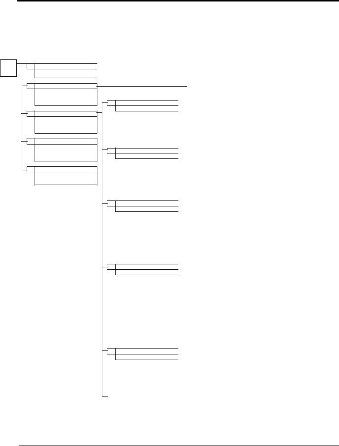
The menu structure for all access levels are the same for the Operation, Initialize, Auto-tuning and Modified constants sections. The Programming section menu structure for each access level is as follows:
Quick-Start Access Level Structure |
|
|
|
|
|
||||||
|
|
|
|
|
|
|
|
|
|
|
|
|
|
|
|
|
|
|
|
|
|
|
|
MENU |
|
|
Programming |
|
|
|
|
|
Data Name |
|
Data Entry |
|
|
|
|
|
|
|
|
||||
|
|
|
|
|
|
|
|
|
|
|
|
|
|
|
|
|
|
|
|
|
|
|
|
Basic Access Level Structure |
|
|
|
|
|
|
|
||||
|
|
|
|
|
|
|
|
|
|
|
|
|
|
|
|
|
|
|
|
|
|
|
|
MENU |
|
|
Programming |
|
|
|
Function Level |
|
Data Name |
|
Data Entry |
|
|
|
|
|
|
|
|||||
|
|
|
|
|
|
|
|
|
|
|
|
|
|
|
|
|
|
|
|
|
|||
Advanced Access Level Structure |
|
|
|
|
|
||||||
|
|
|
|
|
|
|
|
|
|
|
|
|
|
|
|
|
|
|
|
|
|
|
|
MENU |
|
|
Programming |
|
Group Level |
|
Function Level |
|
Data Name |
|
Data Entry |
|
|
|
|
|
|
||||||
|
|
|
|
|
|
|
|
|
|
|
|
VS-616G5 Programming Manual |
5 |

Introduction
Software Version Explanation
Yaskawa recognizes the need to continuously improve product quality. This product may receive feature enhancements in the form of software or hardware changes. New programming parameters will be added to the latest programming manual. When a new parameter is added a software version note will be placed next to the parameter.
Software Version Example:
A1-00 Language Selection |
Select Language |
Q |
Q |
Q |
Q |
Select the language displayed on the digital operator according to the following table:
Setting |
Description |
0English (factory default)
1Japanese
2Deutsche <1110>


3Francais <1110> 


4Italiano <1110>


5Espanol <1110> 


6Portugues <1110> 


This version note <1110> indicates that five additional languages have been added with software version 1110.
The part number of the main control printed circuit board on the drive reflects the software version. The software version normally increases to a higher number with newer versions. Please consult the factory for details.
PCB Part Number Example: ETC615991-S1110  Software version 1110
The VS-616G5 ships preset to open loop vector control, quick-start access level. This publication describes all Quick-Start, Basic and Advanced parameters. For installation and simplified Quick-Start parameters, please refer to YEA-TOA-S616-10.12C.
6 |
VS-616G5 Programming Manual |
VS-616G5 Parameter Tree
VS-616G5 Parameter Tree
Menu
Operation
Inverter operation is enabled.
Inverter status is displayed.
A |
Initialize |
Language selection in LCD display. Constant access levels, control method selection and initializing passwords.
Programming
Parameters are set/read. Items to be set/ read vary depending on the access level setting.
Auto-tuning
Motor parameters are automatically set by inputting turning data (motor nameplate values) when performing vector.
Modified Constants
Only parameters that have been changed from the factory setting are set/read.
|
U |
Monitoring Items |
|
||
|
|
|
|
|
Monitor |
|
|
|
|
|
|
BApplication Application
CTuning Tuning
DReference Reference
|
E |
Motor Parameters |
|
||
|
|
|
|
|
Motor |
FOption Option
|
H |
Control Circuit Terminals |
|
||
|
|
Terminal |
|
|
|
LProtection Protection
O |
Digital Operator |
|
Operator |
|
|
|
Group |
Function |
Display |
Access Level |
|
|
|
|
|
|
|
|
|
|
|
U1 |
Status monitoring |
Monitor |
Q, B, A |
|
|
|
|
|
|
U2 |
Fault trace |
Fault Trace |
Q |
|
|
|
|
|
|
U3 |
Fault history |
Fault History |
Q |
|
|
|
|
|
|
A1 |
Initialization |
Initialize |
Q |
|
|
|
|
|
|
A2 |
User setting parameter |
User Parameters |
A |
|
|
|
|
|
|
B1 |
Operation method selection |
Sequence |
Q, B, A |
|
||||
|
|
|
|
|
|
B2 |
DC injection braking |
DC Braking |
B |
|
|
|
|
|
|
B3 |
Speed search |
Speed Search |
A |
|
|
|
|
|
|
B4 |
Timer function |
Delay Timers |
A |
|
|
|
|
|
|
B5 |
PID control |
PID Control |
A |
|
|
|
|
|
|
B6 |
DWELL function |
Reference Hold |
A |
|
|
|
|
|
|
B7 |
Droop control |
Droop control |
A |
|
|
|
|
|
|
B8 |
Energy-saving control |
Energy Saving |
A |
|
|
|
|
|
|
B9 |
Zero Servo |
Zero Servo |
A |
|
|
|
|
|
|
|
|
|
|
|
C1 |
Accel/decel time |
Accel/Decel |
Q, B, A |
|
||||
|
|
|
|
|
|
C2 |
S-curve characteristics |
S-curve Acc/Dec |
A |
|
|
|
|
|
|
C3 |
Motor slip compensation |
Motor-slip Comp |
B. A |
|
|
|
|
|
|
C4 |
Torque compensation |
Torque Comp |
B, A |
|
|
|
|
|
|
C5 |
ASR |
ASR Tuning |
B, A |
|
|
|
|
|
|
C6 |
Carrier frequency |
Carrier Freq |
BA |
|
|
|
|
|
|
C7 |
Hunting prevention |
Hunting Prev |
A |
|
|
|
|
|
|
C8 |
Factory-tuning constant |
Factory Tuning |
A |
|
|
|
|
|
|
|
|
|
|
|
D1 |
Frequency reference value |
Preset Reference |
Q, A |
|
|
|
|
|
|
D2 |
Upper/lower limits |
Reference Limits |
B |
|
|
|
|
|
|
D3 |
Jump frequency |
Jump Frequencies |
B |
|
|
|
|
|
|
D4 |
Sequence |
Sequence |
A |
|
|
|
|
|
|
D5 |
Torque reference |
Torque Control |
A |
|
|
|
|
|
|
|
|
|
|
|
E1 |
V/f pattern |
V/F Pattern |
Q |
|
||||
|
|
|
|
|
|
E2 |
Motor parameters |
Motor Setup |
Q, A |
|
|
|
|
|
|
E3 |
Motor 2 control method |
Motor 2 Ctl Meth |
A |
|
|
|
|
|
|
E4 |
V/f pattern/2 |
V/f Pattern 2 |
A |
|
|
|
|
|
|
E5 |
Motor 2 constants |
Motor 2 Setup |
A |
|
|
|
|
|
|
|
|
|
|
|
F1 |
PG speed control card |
PG Option setup |
Q, B, A |
|
|
|
|
|
|
F2 |
Analog reference card |
A1-14 Setup |
B |
|
|
|
|
|
|
F3 |
Digital input card |
DI-08, 16 Setup |
B |
|
|
|
|
|
|
F4 |
Analog monitor card |
AO-08, 16 Setup |
B |
|
|
|
|
|
|
F5 |
Digital output card |
DO-02 Setup |
B |
|
|
|
|
|
|
F6 |
Digital output card |
DO-08 Setup |
B |
|
|
|
|
|
|
F7 |
Pulse monitor card |
PO-36F Setup |
B |
|
|
|
|
|
|
F8 |
SI-F/G card |
SI-F/G |
B |
|
|
|
|
|
|
F9 |
DDS-B/SI-B card |
DDSS/SI-B |
B |
|
|
|
|
|
|
|
|
|
|
|
H1 |
Sequence input |
Digital Inputs |
B |
|
||||
|
|
|
|
|
|
H2 |
Sequence output |
Digital Outputs |
B |
|
|
|
|
|
|
H3 |
Analog input |
Analog Inputs |
B, A |
|
|
|
|
|
|
H4 |
Analog output |
Analog Outputs |
B |
|
|
|
|
|
|
H5 |
MODBUS communication (RS-485) |
Serial Com Setup |
A |
|
|
|
|
|
|
|
|
|
|
|
L1 |
Motor electric thermal overload relay |
Motor Overload |
B |
|
||||
|
|
|
|
|
|
L2 |
Momentary power loss ride-through |
PwrLoss Ridethru |
B, A |
|
|
|
|
|
|
L3 |
Stall prevention |
Stall Prevention |
B, A, F |
|
|
|
|
|
|
L4 |
Frequency Detection |
Ref Detection |
B, A |
|
|
|
|
|
|
L5 |
Fault retry |
Fault Restart |
B |
|
|
|
|
|
|
L6 |
Overtorque detection |
Torque Detection |
B, A |
|
|
|
|
|
|
L7 |
Torque limit |
Torque Limit |
B |
|
|
|
|
|
|
L8 |
Hardware protection |
Hdwe Protection |
B, A |
|
|
|
|
|
|
|
|
|
|
|
O1 |
Display selection |
Monitor Select |
B, A |
|
||||
|
|
|
|
|
|
O2 |
Key selection |
Key Selections |
B, A |
|
|
|
|
|
VS-616G5 Programming Manual |
7 |

This page intentionally left blank.
8 |
VS-616G5 Programming Manual |

Section A: Initialization Parameters
A1 Initialization Set-up
|
V/f |
V/f w/PG |
Open Loop |
Flux |
|
Vector |
Vector |
||
|
|
|
Main Menu: Initialize <ENTER>
A Initialization Parameters
A1 Initialization Set-up
A1-00 Language Selection |
Select Language |
Q |
Q |
Q |
Q |
Select the language displayed on the digital operator according to the following table:
|
|
|
Setting |
Description |
|
|
|
|
|
|
|
|
|
|
|
|
|
|
|
|
|
|
|
|
|
|
|
|
0 |
English (factory default) |
|
|
|
|
|
|
|
|
|
|
|
|
|
|
|
|
|
|
|
|
|
|
|
|
1 |
Japanese |
|
|
|
|
|
|
|
|
|
|
|
|
|
|
|
|
|
|
|
|
|
|
|
|
2 |
Deutsch <1110> |
|
|
|
|
|
|
|
|
|
|
|
|
|
|
|
|
|
|
|
|
|
|
|
|
3 |
Francais <1110> |
|
|
|
|
|
|
|
|
|
|
|
|
|
|
|
|
|
|
|
|
|
|
|
|
4 |
Italiano <1110> |
|
|
|
|
|
|
|
|
|
|
|
|
|
|
|
|
|
|
|
|
|
|
|
|
5 |
Espanol <1110> |
|
|
|
|
|
|
|
|
|
|
|
|
|
|
|
|
|
|
|
|
|
|
|
|
6 |
Portugues <1110> |
|
|
|
|
|
|
|
|
|
|
|
|
|
|
|
|
|
|
|
|
|
A1-01 Parameter Access Level |
Access Level |
|
|
|
|
|
|
|||||
Q |
|
Q |
|
Q |
Q |
|||||||
This parameter allows the “masking” of parameters according to user level. See the following table: |
||||||||||||
|
|
|
|
|
|
|
|
|
|
|
|
|
|
Setting |
|
|
Description |
|
|
|
|
|
|
|
|
|
|
|
|
|
|
|
|
|
|
|
|
|
|
0 |
|
|
Operation Only |
|
|
|
|
|
|
|
|
|
|
|
|
|
|
|
|
|||||
|
1 |
|
|
User Program - Accesses parameters selected by OEM (A2-01 to A2-32). |
|
|
|
|||||
|
|
|
|
|
|
|
|
|||||
|
2 |
|
|
Quick Start Level (factory default) - For maintenance-level programming. |
|
|
|
|||||
|
|
|
|
|
|
|
|
|
|
|
|
|
|
3 |
|
|
Basic Level - For basic programming in most applications. |
|
|
|
|
|
|
|
|
|
|
|
|
|
|
|
|
|
||||
|
4 |
|
|
Advanced Level - For advanced programming in special applications. |
|
|
|
|
||||
|
|
|
|
|
|
|
|
|
|
|
|
|
A1-02 Control Method Selection Control Method
Select the control method best suited for your application.
Q |
Q |
Q |
Q |
|
|
|
|
Setting |
Description |
0V/f Control - For general-purpose and multiple motor applications.
1V/f with PG Feedback - For general-purpose applications requiring closed loop speed control.
2Open Loop Vector (factory default) - For applications requiring precise speed control, quick response and higher torque at low speeds (150% torque below 1Hz).
3Flux Vector - For applications requiring very precise speed and torque control at a wide speed range including 0 speed. Uses encoder feedback.
VS-616G5 Programming Manual |
9 |

Section A: Initialization Parameters
A1 Initialization Set-up
|
V/f |
V/f w/PG |
Open Loop |
Flux |
|
Vector |
Vector |
||
|
|
|
A1-03 Operator Status |
Init Parameters |
Q |
Q |
Q |
Q |
Use this parameter to reset the inverter to its factory default settings. Initialize the inverter after changing the control PCB, or after selecting language (A1-00), control method (A1-02), or inverter capacity
(O2-04).
Setting |
Description |
|
|
0 |
No Initialization (factory default) |
|
|
1110 |
User Initialization - resets the inverter to user-specified initial |
|
values. To set user-specified initial values, make all required |
|
changes to parameter settings, then set O2-03 to “1”. The |
|
inverter will memorize all current settings as the user-specified |
|
initial values. Up to 50 changed parameters can be stored. |
|
|
2220 |
2-Wire Initialization - terminal 1 becomes FWD run command |
|
and terminal 2 becomes REV run command. All other param- |
|
eters are reset to their original factory default settings. |
|
|
3330 |
3-Wire Initialization - terminal 1 becomes run command, termi- |
|
nal 2 becomes stop command and terminal 3 becomes FWD/ |
|
REV run selection. All other parameters are reset to their orig- |
|
inal factory default settings. |
|
|
A1-04 Password Entry |
Enter Password |
Q |
Q |
Q |
Q |
Parameter A1-04 is used to enter a password into the inverter, to be able to make adjustments to locked parameters.
Password protection is provided for:
A1-01 Access Level
A1-02 Control Method
A1-03 Initialization
A2-01 to A2-32 User Parameters (If selected)
10 |
VS-616G5 Programming Manual |
Section B: Application Parameters
A2 User Parameters and B1 Sequence
|
V/f |
V/f w/PG |
Open Loop |
Flux |
|
Vector |
Vector |
||
|
|
|
A2 User’s Parameters
The user can select up to 32 parameters for quick-access programming. By setting the user access level (A1-01) to “User Program”, only the parameters selected in function A2 can be accessed by the user.
Parameter A1-01 must be set to 4 (advanced access level) to input parameter numbers into A2-01 through A2-32, and then A1-01 must be set to 1 (User Level) for only the user selected parameters to be viewed.
Main Menu: Programming <ENTER>
B Application Parameters
B1 Sequence
B1-01 |
Frequency Reference Selection |
Reference Source |
B1-02 |
Operation Method Selection |
Run Source |
Q |
Q |
Q |
Q |
|
|
|
|
Q |
Q |
Q |
Q |
|
|
|
|
Frequency reference and run command can be set independently as shown below:
Setting |
Description |
|
|
0 |
Command from digital operator |
|
|
1 |
Command from control circuit terminal (factory default) |
|
|
2 |
Command from serial communication |
|
|
3 |
Command from option card |
|
|
4 |
EWS (Reference from CP-717)* <1110> |
|
This setting will be used with the CP-717 to run and change |
|
the reference through DP-RAM. |
|
|
*Setting parameter B1-01 or B1-02 to 4 allows reference and/or run source from CP-717 when either CP-916 or CP-216 option cards are installed.
By depressing the LOCAL/REMOTE key on the digital operator, the operation mode can be selected as shown below:
Local: |
Operation according to frequency reference and run command from digital operator. |
Remote: |
Operation according to frequency reference and run command set by B1-01 and B1- |
|
02. |
The digital operator is reset to remote operation when power is cycled.
VS-616G5 Programming Manual |
11 |

Section B: Application Parameters
B1 Sequence
B1-03 Stopping Method Selection |
Stopping Method |
|
|
|
|
|
V/f |
V/f w/PG |
Open Loop |
Flux |
|
Vector |
Vector |
|||
|
|
|||
|
|
|
|
|
Q |
Q |
Q |
Q |
|
|
|
|
|
This function selects the stopping method suitable for the particular application.
Setting |
Description |
|
|
0 |
Ramp to stop (factory default) |
|
|
1 |
Coast to stop |
|
|
2 |
DC injection to stop |
|
|
3 |
Coast to stop with timer |
|
|
· Ramp to Stop (B1-03 = “0”)
Output Frequency |
|
|
|
|
|
|
|
Decel time 1 (C1-02) |
|||||
|
|
|
|
|
|
|
|||||||
|
|
|
|
|
|
|
|
|
|
|
|||
Zero Speed Level (Frequency at |
|
|
|
|
|
|
|
|
|
|
|
||
|
|
|
|
|
|
|
|
|
|
|
|||
|
|
|
|
|
|
|
|
|
|
||||
DC Injection Braking Start - B2-01) |
|
|
|
|
|
|
|
|
|
|
|
||
|
|
|
|
|
|
|
|
|
|
||||
Factory Default: 0.5Hz |
|
|
|
|
|
|
|
|
|
|
|||
|
|
|
|
|
|
|
|
|
|
|
|
||
|
|
|
|
|
DC injection Braking Time |
||||||||
|
|
|
|
|
at Stop (B2-04) |
||||||||
|
|
|
|
|
Factory Default: 0.5 s |
||||||||
Run Command |
|
|
|
|
|
|
OFF |
||||||
ON |
|
|
|||||||||||
|
|
|
|
|
|
|
|
|
|
|
|
||
Figure 1 Stopping Method - Ramp to Stop
Upon removal of the FWD (REV) run command, the motor decelerates at a rate determined by the time set in deceleration time 1 (C1-02) and DC injection braking is applied after the minimum output frequency (E1-09) has been reached. If the deceleration time is set too short or the load inertia is large, an overvoltage fault (OV) may occur during deceleration. In this case, increase the deceleration time or install an optional braking transistor and/or braking resistor (braking transistors are provided as standard for units 230V 7.5kW and smaller, 460V 15kW and smaller).
Braking torque: without braking resistor, approx. 20% of motor rated torque with braking option, approx. 150% of motor rated torque
12 |
VS-616G5 Programming Manual |

Section B: Application Parameters
B1 Sequence
|
V/f |
V/f w/PG |
Open Loop |
Flux |
|
Vector |
Vector |
||
|
|
|
· Coast to Stop (B1-03 = “1”)
Output frequency |
|
|
|
|
Inverter output is shut OFF |
|
Run command |
|
|
|
|
when stop command is given. |
|
|
|
|
|
|
|
|
|
|
|
|
OFF |
||
ON |
|
|||||
|
|
|
|
|
|
|
Figure 2 Stopping Method - Coast to Stop
Upon removal of the FWD (REV) run command, the motor starts to coast. After a stop command is given, a run command is accepted and operation will start after the minimum baseblock time (L2-03) elapses. If there is a possibility that a run command might be entered before the motor has come to a stop, the speed search function (B3) or Coast to Stop with Timer 1 (B1-03 = “3”) should be employed.
· DC Injection Braking to Stop (B1-03 = “2”)
Output Frequency
Inverter Output OFF during Minimum Baseblock Time (L2-03) Factory Default: 0.5s
Run Command
ON
|
|
|
|
|
|
|
|
|
DC injection |
|
|
|
|
B2-04 x 10 |
|
|
|
|
|
|
|
|
|
|
|
|
|
||
|
|
|
|
|
|
|
|
|
|
|
|
|
||
|
|
|
|
|
|
|
|
|
|
|
|
|
||
|
|
|
|
|
|
|
|
|
|
|
|
|
|
|
|
|
|
|
|
|
|
|
|
||||||
|
|
|
|
|
|
|
|
|
Braking Time |
|
|
|
|
|
|
|
|
|
|
|
|
|
|
|
|
DC injection Braking Time |
|||
|
DC injection Braking Time |
|||||||||||||
|
|
|
at Stop (B2-04) |
|||||||||||
|
at Stop (B2-04) |
|
|
|||||||||||
|
|
|
|
|
|
|
||||||||
|
Factory Default: 0.0s |
|
|
|
|
|
|
|||||||
|
|
|
|
|
|
|
||||||||
|
|
OFF |
|
|
|
|
|
|
||||||
|
|
|
|
|
|
|
|
|||||||
Figure 3 Stopping Method - DC Injection Braking to Stop
Upon removal of the FWD (REV) run command, the motor brakes to stop, according to the DC injection braking time at stop set in B2-04. If this value is set to “0” (factory default), DC injection braking is disabled, and the motor coasts to stop. When choosing this function, note that the actual stop time is the time set in B2-04 multiplied by 10 (see Figure 3 above). This stopping method is disabled during flux vector control. Braking duty cycle should allow excess motor heat to dissipate.
VS-616G5 Programming Manual |
13 |

Section B: Application Parameters
B1 Sequence
|
V/f |
V/f w/PG |
Open Loop |
Flux |
|
Vector |
Vector |
||
|
|
|
· Coast to Stop with Timer 1 (B1-03 = “3 ”)
Output Frequency |
|
|
Decel Time 1 |
|
|
|
|
||
|
|
|
|
|
|
||||
|
|
|
|
|
|
|
|||
|
|
|
(C1-02) |
|
|
|
|
||
|
|
|
|
|
|
Accel Time 1 |
|||
|
|
|
|
|
|
(C1-01) |
|||
|
|
Coasting |
|
|
|
|
|||
FWD (REV) |
|
|
|
|
|
|
|
|
Time |
|
|
|
|
|
|
||||
|
|
|
|
|
|
|
|
|
|
Run Command |
ON |
|
ON |
|
|
ON |
|
||
Run Command Disabled
Figure 4 Stopping Method - Coast to Stop w/ Timer
After a stop command is given, a run command is not accepted while the coast to stop timer elapses (same as Decel 1). After the timer runs out, another run command must be given for the inverter to begin acceleration. This stopping method is disabled during flux vector control.
B1-04 Prohibition of Reverse Operation |
Reverse Oper |
B |
B |
B |
B |
|
|
|
|
|
|
A “reverse run disabled” setting does not allow a reverse run command from the control circuit terminal or the digital operator. This setting is used in applications where a reverse run command is undesirable.
Setting |
Description |
|
|
0 |
Reverse run enabled (factory default) |
|
|
1 |
Reverse run disabled |
|
|
14 |
VS-616G5 Programming Manual |

|
|
Section B: Application Parameters |
|||||
|
|
|
|
|
B1 |
Sequence |
|
|
|
|
|
|
|
|
|
|
|
|
V/f |
V/f w/PG |
Open Loop |
Flux |
|
|
|
|
Vector |
Vector |
|||
|
|
|
|
|
|||
B1-05 Operation Selection at Zero Speed |
Zero Speed Oper |
|
|
|
|
|
|
|
- |
- |
|
- |
A |
||
|
|
|
|
|
|
|
|
During flux vector control, select an operation mode to be employed when the frequency reference (analog input) drops below the minimum output frequency (El -09). During V/f or open loop vector control, baseblock is applied when the output frequency drops below the minimum output frequency (El -09).
|
Setting |
Description |
|
|
|
|
|
|
|
|
|
|
|
|
|
|
|
|
0 |
E1 -09 disabled, run according to frequency reference (factory default) |
|
|
||||
|
|
|
|
|
|
|
|
|
|
1 |
Baseblock |
|
|
|
|
|
|
|
|
|
|
|
|
|
|
|
|
2 |
Run at minimum output frequency (E1-09) |
|
|
|
|
|
|
|
|
|
|
|
|
|
|
|
|
3 |
Zero-speed operation (internal speed reference is set to “0”) |
|
|
|
|
|
|
|
|
|
|
|
|
|
|
|
|
|
|
|
|
|
|
||
B1-06 Input Scan Time |
Cntl Input Scans |
|
B |
B |
|
B |
B |
|
|
|
|
|
|
|
|
|
|
This parameter selects the microprocessor scan time for reading sequence input data from the control circuit terminals.
Setting |
Description |
|
|
0 |
2ms scan time for 2 scans |
|
|
1 |
5ms scan time for 2 scans (factory default) |
|
|
Set to “0” when a quicker response is needed from the control circuit terminals.
B1-07 Operation Selection After Switch to Remote Mode LOC/REM RUN Sel
A |
A |
A |
A |
|
|
|
|
Parameter b1-07 determines how the inverter will function when switching between local and remote operation. This function prevents the motor from running when switching between local/remote and the inverter is controlled from the digital operator.
Setting |
Description |
0(Cycle Extrn RUN) - If the run command is closed when switching from local control to remote control, the inverter will not run. The run command must be cycled for the inverter to run. (factory default)
1(Accept Extrn RUN) - If the run command is closed, when switching from local control to remote control, the inverter will run.
VS-616G5 Programming Manual |
15 |
Section B: Application Parameters |
|
|
|
|
|
|
|
|
|||
B2 |
DC Braking |
|
|
|
|
|
|
|
|
|
|
|
|
|
|
|
|
|
|
|
|
|
|
|
|
|
|
|
|
V/f |
V/f w/PG |
Open Loop |
|
Flux |
|
|
|
|
|
|
|
Vector |
|
Vector |
|||
|
|
|
|
|
|
|
|
|
|||
|
|
|
|
|
|
|
|
|
|||
B1-08 Run Command Acceptance During Programming |
RUN CMD at PRG |
|
A |
A |
A |
|
A |
||||
|
|
|
|
|
|
|
|
|
|||
|
As a safety precaution the drive will not respond to a change in the run command when the digital |
||||||||||
|
operator is being used to set or adjust parameters.This parameter will allow the drive to accept or |
|
|||||||||
|
reject a change in the run command when the digital operator is being used to change or adjust param- |
||||||||||
|
eters. <1110> |
Table 1: |
|
|
|
|
|
|
|||
|
|
|
|
|
|
|
|
|
|||
|
|
|
|
|
|
|
|
|
|
|
|
|
|
Setting |
|
Description |
|
|
|
|
|
|
|
|
|
|
|
|
|
||||||
|
|
0 |
Run command is disabled when drive is in the programming mode. (factory default) |
|
|
|
|||||
|
|
|
|
|
|
|
|
|
|
||
|
|
1 |
Run command is enabled when the drive is in the program mode |
|
|
|
|
|
|
||
|
|
|
|
|
|
|
|
|
|
|
|
B2 |
DC Braking |
|
|
|
|
|
|
|
|
|
|
|
|
|
|
|
|
||||||
B2-01 DC Braking Frequency (Zero Speed Level) |
DCInj Start Freq |
|
B |
B |
B |
|
B |
||||
|
Setting Range: |
0.0 to 10.0Hz |
|
|
|
|
|
|
|
|
|
|
|
|
|
|
|
|
|
|
|||
|
Factory Default: |
0.5Hz |
|
|
|
|
|
|
|
|
|
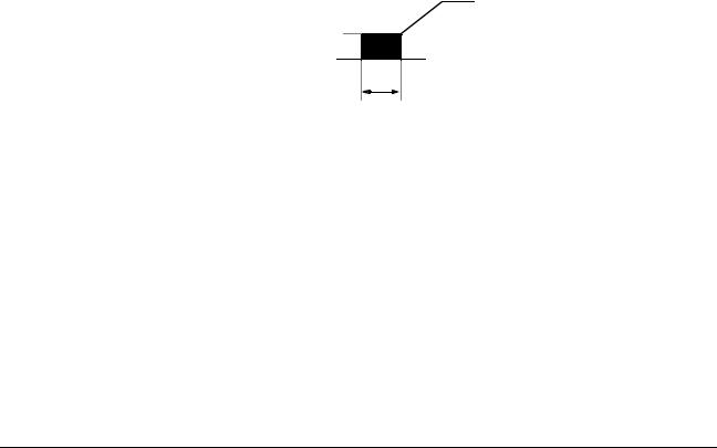
Sets the frequency at which DC injection braking (or initial excitation for flux vector control) starts, in units of 0.1 Hz. When B2-01 < E1-09, DC injection braking starts from the minimum frequency reference (E1-09).
B2-01
DC Injection
Braking Frequency
B2-03
DC Injection Braking
Time at Start
Figure 5 DC Injection Braking at Starting
B2-02 DC Braking Current |
DCInj Current |
B |
B |
B |
- |
|
Setting Range: |
0 to 100% |
|
|
|
|
|
|
|
|
|
|
||
Factory Default: |
50% |
|
|
|
|
|
DC injection braking current is set as a percentage of inverter rated current. In flux vector control mode, initial excitation is performed according to the motor no-load current set in E2-03. This parameter should not be set unnecessarily high or motor overexcitation may occur.
16 |
VS-616G5 Programming Manual |

|
|
|
Section B: Application Parameters |
|||||
|
|
|
|
|
B2 |
DC Braking |
||
|
|
|
|
|
|
|
|
|
|
|
|
|
V/f |
V/f w/PG |
Open Loop |
Flux |
|
|
|
|
|
|
Vector |
Vector |
||
|
|
|
|
|
|
|
||
B2-03 DC Braking Time at Start |
DCInj Time@Start |
|
|
|
|
|
|
|
|
B |
B |
|
B |
B |
|||
Setting Range: |
0.00 to 10.00s |
|
|
|
|
|
|
|
|
|
|
|
|
|
|
||
Factory Default: |
0.00s |
|
|
|
|
|
|
|
DC injection braking at start can be used to stop a spinning motor (or when motor rotation direction is unknown) prior to running. DC injection braking time at start (or initial excitation for flux vector control) is set in units of 0.1 second. When B2-03 is set to “0”, DC injection braking is disabled and acceleration starts from the minimum output frequency.
B2-04 DC Braking Time at Stop |
DCInj Time@Stop |
B |
B |
B |
B |
|
Setting Range: |
0.00 to 10.00s |
|
|
|
|
|
|
|
|
|
|
||
Factory Default: |
0.00s |
|
|
|
|
|
DC injection braking time at stop (or initial excitation for flux vector control) is set in units of 0.1 second. When B2-04 is set to “0”, DC injection braking is disabled, and the inverter output shuts OFF.
E1-09
Min. Output Frequency
B2-04
DC injection Braking
Time at Stop
Figure 6 DC Injection Braking Time at Stop
When coast to stop is selected as the stopping method (B1-03), DC injection braking at stop is disabled.
B2-08 Magnetic Flux Compensation Level <1110> |
FieldComp |
- |
- |
A |
A |
|
Setting Range: |
0 to 500% |
|
|
|
|
|
|
|
|
|
|
||
Factory Default: |
0% |
|
|
|
|
|
This parameter allows the magnetizing motor flux to be boosted when starting the motor. This parameter will facilitate a quick ramp-up of the torque reference and magnetizing current reference to reduce motor slip during start. A setting of 100% equals motor no-load current E1-09. This flux level will be applied below Minimum Output Frequency (E1-09) until the DC Injection Time at Start (B2-03) expires. This parameter is useful when starting motors that are relatively larger than the inverter, due to the requirement for increased magnetizing current. This parameter may also compensate for reduced starting torque due to motor circuit inefficiencies.
VS-616G5 Programming Manual |
17 |

Section B: Application Parameters
B3 Speed Search
|
V/f |
V/f w/PG |
Open Loop |
Flux |
|
Vector |
Vector |
||
|
|
|
B3 Speed Search
When starting into a coasting motor, use the speed search command or DC injection braking at start, to prevent a drive trip and motor burnout.
This function allows the restart into a coasting motor without the necessity to stop. It is useful during inverter bypass operation, when switching between the motor receiving power directly from the line and from the inverter. Two interlocking contactors must be employed for commercial power switchover to prevent line power from being applied to the inverter output terminals.
Set the multi-function contact input selection (H1-01 to H1-06) to “61” (start search command from maximum output frequency), “62” (start search command from the set frequency), or “64” (start search command from the SFS frequency when baseblock is applied).
B3-01 Speed Search after Run Command |
SpdSrch at Start |
A |
- |
|
A |
- |
|
|
|
|
|
|
|
|
|
|
|
|
|
|
|
|
|
|
Setting |
Description |
|
|
|
|
|
0Speed search disabled, the motor accelerates to the set frequency from the min. frequency reference after run command is given (factory default).
1Speed search enabled after run command is given, according to multi-func- tion contact input selection. When using an encoder, the motor accelerates/ decelerates to the set frequency from the motor speed.
Note: This parameter is disabled except when (A1-02=1) (V/F w/PG Fdbk) or 3 (Flux Vector)
B3-02 Speed Search Detection Current Level |
SpdSrch Current |
A |
- |
A |
- |
|
Setting Range: |
0 to 200% |
|
|
|
|
|
|
|
|
|
|
||
Factory Default: |
150% |
|
|
|
|
|
After power loss and recovery, speed search begins to ramp the frequency down from a specified point in order to locate the frequency of the spinning motor. During initial speed search the inverter’s output current exceeds the speed search detection current level. This level is set as a percentage of inverter rated current. When the inverter’s output current is less than the speed search detection level, the frequency is interpreted as the speed agree level, and the inverter accelerates/decelerates to the specified frequency.
Note: Factory setting defaults to 150 when A1-02=0 (V/F Control). When A1-02=2 (Open Loop Vector), the default is 100.
18 |
VS-616G5 Programming Manual |
Section B: Application Parameters
B4 Delay Timers
|
V/f |
V/f w/PG |
Open Loop |
Flux |
|
Vector |
Vector |
||
|
|
|
B3-03 Speed Search Deceleration Time |
SpdSrch Dec Time |
A |
- |
A |
- |
|
Setting Range: |
0.1 to 10.0s |
|
|
|
|
|
|
|
|
|
|
||
Factory Default: |
2.0s |
|
|
|
|
|
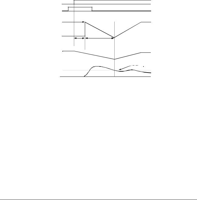
Sets deceleration time during speed search in units of 0.1 second. When speed search deceleration time is set to 0.0 second, speed search is disabled. The speed search deceleration time should be set to be somewhat faster than the decel rate of coasting motor. Build an input sequence so that the speed search command is input at the same time or prior to the FWD (REV) run command. If the run command is input before the search command, the search command is not effective. Below is a timing diagram of the search command input:
FWD (REV) Run Command |
|
|
ON |
Speed Search Command |
ON |
|
|
Max. Output Frequency, |
|
Speed Search |
|
Frequency Reference at |
|
Decel Time (B3-03) |
|
Run Command Input, |
|
|
|
|
|
|
|
or SFS Output Frequency |
|
|
|
Output Frequency |
|
|
|
|
Min. Baseblock |
Speed Search |
|
|
Time (L2-03) |
Operation |
|
Motor Speed |
|
|
|
|
Coasting |
Accelerating |
|
|
|
|
Speed Agree Detected |
B3-02 |
|
|
Output Current |
|
|
|
|
Figure 7 Search Command Input Timing Diagram
B4 Delay Timers
The inverter input and output contacts can be used in place of an external timer. When multi-function contact input (H1-__ = “18”) is closed, a multi-function contact output (H2-__ = “12”) can be set to close after the On-delay time (B4-01) has expired. When multi-function contact input (H1-__ = “18”) is opened, a multi-function contact output (H2-__ = “12”) can be set to open after the Off-delay time (B4-01) has expired. This function operates independently of any action the inverter is performing.
B4-01 On-delay Timer |
Delay-ON Timer |
A |
A |
A |
A |
Setting Range: |
0.0 to 100.0s |
|
|
|
|
|
|
|
|
||
Factory Default: |
0.0s |
|
|
|
|
Sets the ON-delay time in units of 0.1 second. The multi-function input must be “closed” for longer than the ON-delay timer for the multi-function output to close.
VS-616G5 Programming Manual |
19 |

Section B: Application Parameters
B5 PID Control
|
V/f |
V/f w/PG |
Open Loop |
Flux |
|
Vector |
Vector |
||
|
|
|
B4-02 Off-delay Timer |
|
|
|
|
|
|
|
Delay-OFF Timer |
|
A |
|
|
|
A |
|
A |
|
|
A |
||||||||||||||||
Setting Range: |
|
0.0 to 100.0s |
|
|
|
|
|
|
|
|
|
|
|
|
|
|
|
|
|
|
|
|
|
|
|
|
|
|
|
|
|
||||
|
|
|
|
|
|
|
|
|
|
|
|
|
|
|
|
|
|
|
|
|
|
|
|
|
|
|
|
|
|
||||||
Factory Default: |
|
0.0s |
|
|
|
|
|
|
|
|
|
|
|
|
|
|
|
|
|
|
|
|
|
|
|
|
|
|
|
|
|
||||
Sets the OFF-delay time in units of 0.1 second. The multi-function input must be “open” for longer |
|||||||||||||||||||||||||||||||||||
than the OFF-delay timer for the multi-function output to open. |
|
|
|
|
|
|
|
|
|
|
|
|
|
|
|
||||||||||||||||||||
Multi-function Contact |
|
|
|
|
|
|
|
|
|
|
|
|
|
|
|
|
|
|
|
|
|
|
|
|
|
|
|
|
|
|
|
|
|
||
Input: Timer Function |
|
|
|
|
|
|
|
|
|
|
|
|
|
|
|
|
|
|
|
|
|
|
|
|
|
|
|
|
|
|
|
|
|
||
|
|
|
ON |
|
|
|
|
|
|
|
|
|
|
|
ON |
|
|
|
|
|
|
|
|
|
|
|
|
|
|
|
|||||
|
|
|
|
|
|
|
|
|
|
|
|
|
|
|
|
|
|
|
|
|
|
|
|
|
|
|
|
|
|
|
|
||||
|
|
|
|
|
|
|
|
|
|
|
ON |
|
ON ON |
|
|
|
|
|
|
ON |
|
ON ON |
|
|
|
|
|
||||||||
|
|
|
|
|
|
|
|
|
|
|
|
|
|
|
|
|
|
|
|
|
|
|
|
|
|
|
|
|
|
|
|
|
|
|
|
|
|
|
|
|
|
ON |
|
|
|
|
|
|
|
|
|
|
|
|
|
|
|
|
|
|
ON |
|
|
|
|
|
|
|
|||
Multi-function Contact |
|
|
|
|
|
|
|
|
|
|
|
|
|
|
|
|
|
|
|
|
|
|
|
|
|
|
|
|
|
|
|
|
|
||
Output: Timer Function |
|
|
|
|
|
|
|
|
|
|
|
|
|
|
|
|
|
|
|
|
|
|
|
|
|
|
|
|
|
|
|
|
|
||
|
|
|
|
|
|
|
|
|
|
|
|
|
|
|
|
|
|
|
|
|
|
|
|
|
|
|
|
|
|
|
|
|
|
|
|
|
|
|
B4-01 |
B4-02 |
|
|
|
|
|
|
|
B4-01 |
|
|
|
|
|
|
|
|
B4-02 |
|
|
|
|||||||||||
Figure 8 Timing Diagram of Timer Function
B5 PID Control
The Proportional, Integral and Derivative (PID) control function provides closed-loop control and regulation of a system variable such as temperature or pressure. A control signal based on the difference (or proportion) between a feedback signal and a desired setpoint is produced. Integration and derivative calculations are then performed on this signal, based upon the PID parameter settings (B5-01 to B5-08), to minimize deviation, for more precise control.
Proportional - P
PID refers to the type of action used to control modulating equipment such as valves or dampers. With proportional control, a control signal based on the difference between an actual condition and a desired condition is produced. The difference, such as that between an actual temperature and setpoint is the “error”. The inverter adjusts its output signal related directly to the error magnitude.
Integral - I
The integral action is designed to minimize offset. An integrating term is used to observe how long the error condition has existed, summing the error over time. Once the system has stabilized, the offset would be minimized.
Derivative - D
Overshoot refers to a control loop tendency to overcompensate for an error condition, causing a new error in the opposite direction. Derivative action provides an anticipatory function that exerts a “braking” action on the control loop. When combined, the proportional integral, and derivative actions provide quick response to error, close adherence to the setpoint, and control stability.
20 |
VS-616G5 Programming Manual |

Section B: Application Parameters
Figure 9 PID Block Diagram
Figure 9 PID Block Diagram
VS-616G5 Programming Manual |
21 |

Section B: Application Parameters
B5 PID Control
B5-01 PID Control Mode Selection |
PID Mode |
|
|
|
|
|
V/f |
V/f w/PG |
Open Loop |
Flux |
|
Vector |
Vector |
|||
|
|
|||
|
|
|
|
|
A |
A |
A |
A |
|
|
|
|
|
To enable PID control, set PID control mode selection to “1” or “4”, according to the description below. Also be sure to set terminal 16 function selection (H3-05) to PID feedback (setting: “B”).
Setting |
Description |
|
|
0 |
PID disabled (factory default) |
|
|
1 |
PID enabled (deviation signal is put through derivative control) |
|
|
2 |
PID with feed forward (feedback signal is put through derivative control) |
|
|
3 <1110> |
Reference= Frequency reference + PID output, D is Fdbk |
|
|
4 <1110> |
Reference= Frequency reference + PID output, D is feed-forward |
|
|
Notes:
1.PID with feed forward applies control much quicker than normal PID, without waiting for the deviation signal to build up.
2.A PID inverse feedback signal can be selected by inverting the settings for terminal 16 gain and bias.
Then select the PID control intended value setpoint or detected feedback value setpoint as follows:
Intended Value Setting
The control circuit terminal 16 voltage signal (0 to 10V, -10 to 10V) or multi-step speed parameters H103 to H1-06 can be used to set the PID intended value.
Control circuit terminal 16 voltage signal:
Set reference selection (B1-01) to “1”.
Multi-step speed parameters (H1-03 to H1-06): Set reference selection (B1-01) to “0”.
(combination of multi-step speed references and jog frequency reference)
Detected Value Setting (Feedback)
The control circuit terminal 14 current signal (4 to 20mA) or voltage signals (0 to 10V, -10 to 10V) can be used to set the PID detected value.
Control circuit terminal 14 current signal:
Set terminal 14 signal selection (H3-08) to “2”.
Control circuit terminal 14 voltage signal:
Set terminal 14 signal selection (H3-08) to “0”or “1”.
22 |
VS-616G5 Programming Manual |

Section B: Application Parameters
B5 PID Control
|
V/f |
V/f w/PG |
Open Loop |
Flux |
|
Vector |
Vector |
||
|
|
|
Notes:
1.I value is reset to ”0” when operation stops.
2.The upper limit of the I value can be set by parameter B5-04.
Increase the value of parameter B5-04 to upgrade control capability by integration. If the control system vibrates and it cannot be stopped by adjusting the integral time, output delay time, etc., decrease the set value of parameter B5-04.
3.PID control can be canceled by a multi-function contact input signal.
By setting any of parameters H1-01 to H1-06 to “19” and by closing the contact during running, PID control is disabled and the intended value signal itself is used as a frequency reference signal.
B5-02 PID Control Proportional Gain |
PID Gain |
A |
A |
A |
A |
|
Setting Range: |
0.00 to 25.00 |
|
|
|
|
|
|
|
|
|
|
||
Factory Default: |
1.00 |
|
|
|
|
|
The proportional gain is the value by which the deviation signal is multiplied to generate a new frequency reference.
B5-03 PID Control Integral Time |
PID I Time |
A |
A |
A |
A |
|
Setting Range: |
0.00 to 360.0 seconds |
|
|
|
|
|
|
|
|
|
|
||
Factory Default: |
1.00 seconds |
|
|
|
|
|
The integral calculation sums the deviation over time, which eliminates the offset, thus achieving the intended value. The integral time determines how quickly the integral gain increase is added to the control loop.
B5-04 PID Control Integral Limit |
PID I Limit |
A |
A |
A |
A |
|
Setting Range: |
0.0 to 100.0% |
|
|
|
|
|
|
|
|
|
|
||
Factory Default: |
100.0% |
|
|
|
|
|
The integral limit value eliminates oscillations and improves stability. This value is set as a percentage of maximum output frequency (E1-04).
B5-05 PID Control Derivative Time |
PID D Time |
A |
A |
A |
A |
|
Setting Range: |
0.00 to 10.00 seconds |
|
|
|
|
|
|
|
|
|
|
||
Factory Default: |
0.00 seconds |
|
|
|
|
|
The derivative calculation attempts to control the remaining overshoot left over after the proportion and integral calculations. If the system is approaching the intended value very rapidly, the derivative control produces a strong braking action to prevent overshoot. If the system is already stable with very little deviation change, derivative control has very little effect. The derivative time is used to dampen oscillations and reduce overshoot, thus improving stability. Setting the derivative time to a larger number produces more braking action in the control system.
VS-616G5 Programming Manual |
23 |

Section B: Application Parameters
B5 PID Control
B5-06 PID Control Limit |
PID Limit |
Setting Range: |
0.0 to 100.0% |
Factory Default: |
100.0% |
|
|
|
|
|
V/f |
V/f w/PG |
Open Loop |
Flux |
|
Vector |
Vector |
|||
|
|
|||
|
|
|
|
|
A |
A |
A |
A |
|
|
|
|
|
The PID limit value further eliminates oscillations and improves stability. This value is set as a percentage of maximum output frequency (E1-04).
B5-07 PID Control Offset |
PID Offset |
A |
A |
A |
A |
Setting Range: |
-100.0% to +100.0% |
|
|
|
|
|
|
|
|
||
Factory Default: |
0.0% |
|
|
|
|
The PID offset adds a bias to the calculated PID value, in order to reduce any offset.
B5-08 PID Control Output Primary Delay Time |
PID Delay Time |
A |
A |
A |
A |
|
Setting Range: |
0.00 to 100.0 seconds |
|
|
|
|
|
|
|
|
|
|
||
Factory Default: |
0.00 seconds |
|
|
|
|
|
The output delay time is used to delay changes in the calculated PID value, which can prevent oscillations and improve stability.
Parameters B5-04 and B5-06 to B5-08 are preset at the factory to optimum values for most applications, hence, do not need to be changed. When tuning a system, first adjust the proportional gain until oscillations are reduced. Then adjust the integral time so that minimal deviation is achieved as quickly as possible, without oscillations. Finally, adjust the derivative time to reduce any overshoot at start-up.
B5-09 PID Output Selection <1110> |
Output Level Sel |
A |
A |
A |
A |
|
|
|
|
|
|
The PID output term for the inverter control can be either negative or positive output.
Setting |
Description |
0PID Normal or Forward Output (factory default)
Increase in the manipulated variable when the process variable is larger than the setpoint and decrease the manipulated variable when the process variable is smaller.
1PID Reverse or Inverse Output
Increase the manipulated variable when the process variable is smaller than the setpoint and decrease the manipulated variable when the process variable is larger than the setpoint.
24 |
VS-616G5 Programming Manual |

|
|
|
Section B: Application Parameters |
|||||
|
|
|
|
|
B5 |
PID Control |
||
|
|
|
|
|
|
|
|
|
|
|
|
|
V/f |
V/f w/PG |
Open Loop |
Flux |
|
|
|
|
|
|
Vector |
Vector |
||
|
|
|
|
|
|
|
||
B5-10 PID Output Gain <1110> |
Output Gain |
|
|
|
|
|
|
|
|
A |
A |
|
A |
A |
|||
Setting Range: |
0.0 to 25.0 |
|
|
|
|
|
|
|
|
|
|
|
|
|
|
||
Factory Default: |
1.0 |
|
|
|
|
|
|
|
This parameter sets the gain of the PID output. The PID output can be monitored by parameter U1-37 PID Output Monitor. Refer to PID Block Diagram Figure 9.
B5-11 PID Output Reverse <1110> |
Output Rev Sel |
A |
A |
A |
A |
|
|
|
|
|
|
This parameter is used when the motor is required to change direction during PID operation in response to a negative PID output signal. The PID output can be monitored using parameter U1-37 PID Output Monitor.
Setting |
Description |
0Zero limit (factory default)
When PID output is negative, motor direction is not changed. The PID output is limited to 0.
1Reverse
When PID output is negative the motor will reverse direction.
Note: When Reverse Prohibit B1-04 is selected, reverse will not operate.
B5-12 Loss of Feedback Action <1110> |
Fb Los Det Sel |
A |
A |
A |
A |
|
|
|
|
|
|
This parameter is used to select what action the inverter will take on a loss of PID feedback. A loss of PID feedback occurs when the feedback signal falls below the B5-13 Feedback Loss Detection Level for the time set by B5-14 Feedback Loss Detection Time.
Setting |
Description |
0Disabled (factory default)
PID feedback missing detection is disabled.
1Alarm
PID feedback missing detection is enabled. Operation continues after loss of feedback. The text “Fbl” will be displayed on the digital operator.
2Fault
PID feedback missing detection is enabled. The inverter output to the motor is shut off (the motor is stopped) and “Fbl” is displayed on the digital operator.
VS-616G5 Programming Manual |
25 |

Section B: Application Parameters
B6 Reference Hold
B5-13 PID Feedback Loss Detection Level <1110> |
Fb los Det Lvl |
|
Setting Range: |
0 to 100% |
|
Factory Default: |
1% |
|
|
|
|
|
|
V/f |
V/f w/PG |
Open Loop |
Flux |
|
Vector |
Vector |
|||
|
|
|||
|
|
|
|
|
A |
A |
A |
A |
|
|
|
|
|
This parameter sets the level at which a loss of PID feedback is detected. The PID feedback must be at or below this level for the time defined by B5-14 before a loss of feedback can be detected. A setting of 100% represents 100% of the feedback signal.
B5-14 PID Output Gain <1110> |
Output Gain |
A |
A |
A |
A |
|
Setting Range: |
0.0 to 25.0 |
|
|
|
|
|
|
|
|
|
|
||
Factory Default: |
1.0 |
|
|
|
|
|
This parameter sets the gain of the PID output. The PID output can be monitored by parameter U1-37 PID Output Monitor. Refer to PID Block Diagram Figure 9.
B6 Reference Hold
The reference hold or dwell function is used to temporarily hold the output frequency at a set reference, for a set time, and then start it again. This function can be used when driving a permanent magnet motor, or a motor with a heavy starting load. This pause in acceleration allows the magnets in a permanent magnet motor to synchronize with the stator field of the motor, thus reducing traditionally high starting current.
B6-01 Dwell Frequency Reference at Start |
Dwell Ref @Start |
A |
A |
A |
A |
|
Setting Range: |
0.0 to 400.0Hz |
|
|
|
|
|
|
|
|
|
|
||
Factory Default: |
0.0Hz |
|
|
|
|
|
Sets the dwell frequency reference during acceleration in units of 0.1Hz.
B6-02 Dwell Time at Start |
Dwell Time@Start |
A |
A |
A |
A |
Setting Range: |
0.0 to 10.0s |
|
|
|
|
|
|
|
|
||
Factory Default: |
0.0s |
|
|
|
|
Sets the amount of time that the frequency reference “dwells” during acceleration in units of 0.1s.
B6-03 Dwell Frequency Reference at Stop |
Dwell Ref @Stop |
A |
A |
A |
A |
|
Setting Range: |
0.0 to 400.0Hz |
|
|
|
|
|
|
|
|
|
|
||
Factory Default: |
0.0Hz |
|
|
|
|
|
Sets the dwell frequency reference during deceleration in units of 0.1Hz.
26 |
VS-616G5 Programming Manual |

Section B: Application Parameters
B7 Droop Control and B8 Energy Saving
|
V/f |
V/f w/PG |
Open Loop |
Flux |
|
Vector |
Vector |
||
|
|
|
B6-04 Dwell Time at Stop |
Dwell Time @Stop |
A |
A |
A |
A |
Setting Range: |
0.0 to 10.0s |
|
|
|
|
|
|
|
|
||
Factory Default: |
0.0s |
|
|
|
|
Sets the amount of time that the frequency reference “dwells” during deceleration in units of 0.1s.
B7 Droop Control
The Drooping function reduces the motor speed based on the load torque of the motor.
B7-01 Droop Control Gain |
Droop Quantity |
- |
- |
- |
A |
Setting Range: |
0.0 to 100.0 |
|
|
|
|
|
|
|
|
||
Factory Default: |
0.0 |
|
|
|
|
Parameter b7-01 sets the amount of motor speed reduction when the motor is producing 100% of rated torque. The actual amount of motor speed reduction is based on the ratio of the amount of motor torque and the maximum output frequency (E1-04).
B7-02 Droop Control Delay Time |
Droop Delay Time |
- |
- |
- |
A |
|
Setting Range: |
0.03 to 2.00 |
|
|
|
|
|
|
|
|
|
|
||
Factory Default: |
0.05 |
|
|
|
|
|
Parameter b7-02 sets the response time for the drooping function. Decreasing the droop delay time, will cause the response to become quicker; however, instability may occur.
B8 Energy Saving
This feature can save energy during operation under lightly loaded conditions, by decreasing output voltage, energy-saving operation is made available. Energy saving control is enabled by a multi-func- tion contact input, when control mode selection (A1-02) is set to “0” (V/f Control) or “1” (V/f w/PG Fdbk).
Parameters B8-03, B8-04 and B8-05 are for energy savings in the vector modes. B8-01 and B8-02 are only functional in the V/f modes via a multi-function input command. Parameters B8-03, B8-04 and B8-05 are for automatic energy savings in the vector modes.
B8-01 Energy Saving Gain |
Energy Save Gain |
A |
A |
- |
- |
Setting Range: |
0 to 100% |
|
|
|
|
|
|
|
|
||
Factory Default: |
80% |
|
|
|
|
The output voltage during energy-saving operation is the product of the normal V/f settings (El-03 to E1-10) and the energy saving gain. The output voltage decreases and recovers in the voltage recovery time (L2-04). As the energy saving gain increases, the output voltage increases also. This feature is only enabled by a multi-function contact input.
VS-616G5 Programming Manual |
27 |

Section B: Application Parameters
B8 Energy Savings
|
V/f |
V/f w/PG |
Open Loop |
Flux |
|
Vector |
Vector |
||
|
|
|
B8-02 |
Energy Saving Starting Frequency |
Energy Save Freq |
A |
A |
- |
- |
|
|
Setting Range: |
0.0 to 400.0Hz |
|
|
|
|
|
|
|
|
|
|
|
||
|
Factory Default: |
0.0Hz |
|
|
|
|
|
|
After the multi-function contact input for energy-saving operation closes (H1-__, setting: “63”), the |
||||||
|
output voltage is decreased when the output frequency reaches the energy-saving starting frequency. |
||||||
|
This feature is only enable by multi-function contact input. |
|
|
|
|
||
|
. |
|
|
|
|
|
|
B8-03 |
Automatic Energy Saving <1110> |
Energy Save Sel |
|
|
|
|
|
- |
- |
A |
A |
||||
|
|
|
|
|
|
|
|
This parameter is used to select if Automatic Energy Saving Mode is to be on or off. A multi-function contact input is not required to activate Automatic Energy Saving Mode. This mode of operation automatically searches for the optimum motor voltage required to save energy. This function is separate and not to be confused with parameters B8-01 and B8-02. The energy saving mode that utilizes B8-01 and B8-02 requires a multi-function input to be activated for operation. This Automatic Energy Saving Mode selection does not require a multi-function input to activate operation.
Setting |
Description |
0Disabled (factory default)
Energy saving mode will not be activated under light loads.
1Enabled
The energy saving mode will be activated under light loads.
B8-04 Energy Saving Control Gain |
Energy Save Gain |
- |
- |
A |
A |
|
Setting Range: |
0 to 10.0 |
|
|
|
|
|
|
|
|
|
|
||
Factory Default: |
0.7 |
|
|
|
|
|
The output voltage during energy-saving operation is the product of the normal V/f settings (El-03 to E1-10) and the energy saving gain. The output voltage decreases and recovers according to the EnergySaving Control Time Constant B8-05. As the energy saving gain increases, the output voltage increases also.
Note: When the control mode A1-02=3, the default factory setting becomes 1.0
B8-05 Energy Control Time-Constant |
Energy Save F. T |
- |
- |
A |
A |
|
Setting Range: |
0.00 to 10.00 |
|
|
|
|
|
|
|
|
|
|
||
Factory Default: |
0.50 |
|
|
|
|
|
Parameter B8-05 sets the response time for the Automatic Energy Saving function.
Decreasing the Energy Control Time-Constant, will cause the response to become quicker; however, instability may occur if this is decreased too much.
Note: When control mode A1-02=3, the default factory setting becomes 0.01.
28 |
VS-616G5 Programming Manual |

Section B: Application Parameters
B9 Zero Servo
|
V/f |
V/f w/PG |
Open Loop |
Flux |
|
Vector |
Vector |
||
|
|
|
FWD |
|
Energy |
|
Saving |
|
Command |
|
(Multi-function input |
Fref ³ B8-02 |
setting = “63”) |
|
Fout |
|
Vout |
L2-04 |
|
|
|
V/f Pattern × Energy Saving Gain (B8-01) |
Figure 10 Timing Diagram of Energy Saving Function
B9 Zero Servo
The zero servo function is enabled when the multi-function contact input is set to zero servo command (H1-__ = “72”). The motor position is then memorized when motor speed feedback is less than the zero speed level (B2-01).
B9-01 Zero Servo Gain |
Zero Servo Gain |
- |
- |
- |
A |
Setting Range: |
0 to 100 |
|
|
|
|
|
|
|
|
||
Factory Default: |
5 |
|
|
|
|
Sets the zero-servo position loop gain. When adjusting the gain, the higher the setting, the quicker the response. However, if the gain is set too high, it can cause overshoot and a possible runaway condition.
|
+ |
|
|
|
|
B9-01 |
|
|
|
|
|
|
|
|
|
|
||||
|
|
|
|
|
Kp |
|
|
|
|
|
|
Speed Reference |
|
|
|
|
||||
|
0 |
|
|
|
|
|
|
|
|
|
|
|
|
|
|
|
|
|
||
|
|
|
|
|
|
|
|
|
|
|
|
|
|
|
|
|
||||
|
(Position Ref.) - |
|
|
|
|
|
|
|
|
|
|
|
|
|||||||
|
|
|
|
|
|
|
|
|
|
|
|
|
||||||||
|
|
|
|
|
|
|
|
|
ò |
|
|
|
|
|
|
Motor Speed Feedback |
|
|
|
|
|
|
|
|
|
|
|
|
|
|
|
|
|
|
|
|
|
|
|||
|
|
|
|
Motor |
|
|
|
|
|
|
|
|
|
|
||||||
|
|
|
|
|
|
|
|
|
|
|
|
|
|
|
|
|||||
|
|
|
|
Deviation |
|
|
|
|
|
|
|
|
|
|
||||||
|
|
|
|
Position |
|
|
|
|
|
|
|
|
|
|
||||||
|
|
|
|
|
|
|
|
|
Counter |
|
|
|
|
|
|
|
|
|
|
|
|
Figure 11 Zero Servo Position Loop |
|
|
|
|
|||||||||||||||
B9-02 Zero Servo Bandwidth |
|
|
Zero Servo Count |
|
|
|
|
|||||||||||||
|
|
- |
- |
- |
A |
|||||||||||||||
Setting Range: |
0 to 16383 pulses |
|
|
|
|
|
|
|
|
|
|
|
|
|||||||
|
|
|
|
|
|
|
|
|
|
|
|
|||||||||
Factory Default: |
10 pulses |
|
|
|
|
|
|
|
|
|
|
|
|
|||||||
Sets zero servo bandwidth in units of one pulse. During zero servo control, the multi-function contact output (H2-__ = “33”) is closed until the number of pulses (or bandwidth) is completed. Then the contact output opens.
VS-616G5 Programming Manual |
29 |

Section C: Tuning Parameters
C1 Accel/Decel
|
V/f |
V/f w/PG |
Open Loop |
Flux |
|
Vector |
Vector |
||
|
|
|
.
Zero Servo Function |
ON |
|
|
|
|
OFF |
|
|||||
(Multi-function Input |
|
|
|
|
||||||||
|
|
|
|
|
|
|
|
|
|
|
|
|
H1-__ setting = “72”) |
|
|
|
|
|
|
|
|
|
|
|
|
Zero Speed Level |
|
|
|
|
(Factory Default: 0.5Hz) |
|||||||
Motor Speed |
(B2-01) |
|
|
|
|
|
||||||
|
|
|
|
|
|
|
||||||
|
|
|
|
|
|
|
|
|
|
|
|
|
|
Speed Loop |
|
|
|
|
|||||||
|
|
Zero Servo Loop |
||||||||||
Zero Servo Bandwidth |
|
|
|
|
|
|
|
|
|
|||
|
|
|
|
|
|
|
|
|||||
|
|
|
|
|
|
|
|
|||||
Position Deviation |
(B9-02) |
|
|
|
|
|
|
|
|
|
|
|
Zero Servo Completion |
|
|
|
|
|
|
|
|
||||
|
|
|
|
|
|
|
|
|
|
|
|
|
OFF |
|
|
|
|
|
|
|
|||||
|
|
|
|
ON |
||||||||
(Multi-function Output |
|
|
|
|
|
|
|
|
|
|
|
|
|
|
|
|
|
|
|
|
|
|
|
|
|
H2-__ setting = “33”) |
|
|
|
|
|
|
|
|
|
|
|
|
Figure 12 Timing Diagram of Zero Servo Function
Notes:
1.For multi-function contact input function selection, refer to parameters H1-01 to H1-06.
2.For multi-function contact output function selection, refer to parameters H2-01 to H2-03.
3.This function is only available during flux vector control (Al-02 = “3”).
C Tuning Parameters
C1 Accel/Decel
C1-01 |
Acceleration time 1 |
Accel Time 1 |
C1-02 |
Deceleration time 1 |
Decel Time 1 |
C1-03 |
Acceleration time 2 |
Accel Time 2 |
C1-04 |
Deceleration time 2 |
Decel Time 2 |
C1-05 |
Acceleration time 3 |
Accel Time 3 |
C1-06 |
Deceleration time 3 |
Decel Time 3 |
C1-07 |
Acceleration time 4 |
Accel Time 4 |
C1-08 |
Deceleration time 4 |
Decel Time 4 |
Q |
Q |
Q |
Q |
|
|
|
|
Q |
Q |
Q |
Q |
|
|
|
|
B |
B |
B |
B |
|
|
|
|
B |
B |
B |
B |
|
|
|
|
A |
A |
A |
A |
|
|
|
|
A |
A |
A |
A |
|
|
|
|
A |
A |
A |
A |
|
|
|
|
A |
A |
A |
A |
|
|
|
|
Setting Range: |
0.00 to 6000.0s |
Note: Setting range may be 0.00-600.0 or 0.0-6000.0 depending on the setting of parameter C1-10. Factory Default: 10.0s
Acceleration time sets the time necessary for the output frequency to accelerate from 0Hz to maximum output frequency. Deceleration time sets the time necessary for the output frequency to decelerate from the maximum output frequency to 0Hz.
30 |
VS-616G5 Programming Manual |
 Loading...