


 Loading...
MEMOCON GL120, GL130
120-SERIES I/O MODULES
USER'S MANUAL
MANUAL NO. SIE-C825-20.22C
Manual Contents
This manual describes specifications, connections, and precautions for 120-series I/O Modules. The 120-series I/O Modules are used with the MEMOCON GL120, GL130 Programmable Controllers (PLCs).
Read this manual carefully and be sure to understand the information provided before attempting to install or use 120-series I/O Modules.
Also, keep this manual in a safe place so that it can be used whenever necessary.
Visual Aids
IMPORTANT
 EXAMPLE
INFO
 SUMMARY
Note
TERMS
The following aids are used to indicate certain types of information for easier reference.
Indicates references for additional information.
Indicates important information that should be memorized.
Indicates application examples.
Indicates supplemental information.
Indicates a summary of the important points of explanations.
Indicates inputs, operations, and other information required for correct operation but that will not cause damage to the device.
Indicates definitions of terms used in the manual.
Notice
The following conventions are used to indicate precautions in this manual. Failure to heed precautions provided in this manual can result in injury to people or damage to the products.
 WARNING Indicates precautions that, if not heeded, could possibly result in loss of life or serious injury.
 CAUTION Indicates precautions that, if not heeded, could result in relatively serious or minor injury, damage to the product, or faulty operation.
© Yaskawa, 1998
All rights reserved. No part of this publication may be reproduced, stored in a retrieval system, or transmitted, in any form, or by any means, mechanical, electronic, photocopying, recording, or otherwise, without the prior written permission of Yaskawa. No patent liability is assumed with respect to the use of the information contained herein. Moreover, because Yaskawa is constantly striving to improve its high-quality products, the information contained in this manual is subject to change without notice. Every precaution has been taken in the preparation of this manual. Nevertheless, Yaskawa assumes no responsibility for errors or omissions. Neither is any liability assumed for damages resulting from the use of the information contained in this publication.
iii

CONTENTS
Manual Contents - - - - - - - - - - - - - - - - - - - - - - - - - - - - - - - - - - - - - - - iii Visual Aids- - - - - - - - - - - - - - - - - - - - - - - - - - - - - - - - - - - - - - - - - - - - iii Notice - - - - - - - - - - - - - - - - - - - - - - - - - - - - - - - - - - - - - - - - - - - - - - - iii
1 Introduction and Precautions
1.1 Overview of Manual - - - - - - - - - - - - - - - - - - - - - - - - - - - - - 1-2
1.2 Precautions - - - - - - - - - - - - - - - - - - - - - - - - - - - - - - - - - - - 1-3
1.2.1 Safety Precautions - - - - - - - - - - - - - - - - - - - - - - - - - - - - - - - - - - - - -1-3
1.2.2 Installation Precautions - - - - - - - - - - - - - - - - - - - - - - - - - - - - - - - - - -1-4
1.2.3 Removal Precautions - - - - - - - - - - - - - - - - - - - - - - - - - - - - - - - - - - -1-5
1.2.4 Wiring Precautions - - - - - - - - - - - - - - - - - - - - - - - - - - - - - - - - - - - - -1-6
1.2.5 Application Precautions- - - - - - - - - - - - - - - - - - - - - - - - - - - - - - - - - 1-11
1.2.6 Maintenance - - - - - - - - - - - - - - - - - - - - - - - - - - - - - - - - - - - - - - - - 1-14
1.3 Using This Manual - - - - - - - - - - - - - - - - - - - - - - - - - - - - - 1-15
2 Models and General Specifications of I/O Modules
2.1 General Specifications - - - - - - - - - - - - - - - - - - - - - - - - - - - 2-2
2.2 I/O Modules - - - - - - - - - - - - - - - - - - - - - - - - - - - - - - - - - - - 2-3
2.2.1 Models of I/O Modules - - - - - - - - - - - - - - - - - - - - - - - - - - - - - - - - - -2-3
2.2.2 Overview of I/O Module Specifications - - - - - - - - - - - - - - - - - - - - - - -2-5
2.2.3 Using I/O Modules - - - - - - - - - - - - - - - - - - - - - - - - - - - - - - - - - - - - 2-10
3 Digital I/O Specifications
3.1 Digital Input Module specifications - - - - - - - - - - - - - - - - - - 3-2
3.1.1 100-VAC 16-point Input Module - - - - - - - - - - - - - - - - - - - - - - - - - - - -3-2 3.1.2 200-VAC 16-point Input Module - - - - - - - - - - - - - - - - - - - - - - - - - - - -3-6 3.1.3 12/24-VDC 16-point Input Module - - - - - - - - - - - - - - - - - - - - - - - - - 3-10 3.1.4 12/24-VDC 32-point Input Module - - - - - - - - - - - - - - - - - - - - - - - - - 3-14 3.1.5 12/24-VDC 64-point Input Module - - - - - - - - - - - - - - - - - - - - - - - - - 3-18
3.2 Digital Output Module Specifications - - - - - - - - - - - - - - - - 3-24
3.2.1 100/200-VAC 8-point Output Module - - - - - - - - - - - - - - - - - - - - - - - 3-24 3.2.2 100/200-VAC 16-point Output Module - - - - - - - - - - - - - - - - - - - - - - 3-28 3.2.3 12/24-VDC 8-point Output Module - - - - - - - - - - - - - - - - - - - - - - - - - 3-32 3.2.4 12/24-VDC 16-point Output Module (Sinking) - - - - - - - - - - - - - - - - - 3-36 3.2.5 12/24-VDC 16-point Output Module (Sourcing) - - - - - - - - - - - - - - - - 3-40 3.2.6 12/24-VDC 32-point Output Module - - - - - - - - - - - - - - - - - - - - - - - - 3-44 3.2.7 12/24-VDC 64-point Output Module - - - - - - - - - - - - - - - - - - - - - - - - 3-49 3.2.8 Relay Contact 16-point Output Module - - - - - - - - - - - - - - - - - - - - - - 3-55
3.3 I/O Module Cables - - - - - - - - - - - - - - - - - - - - - - - - - - - - - 3-60
3.3.1 I/O Module Cable Types - - - - - - - - - - - - - - - - - - - - - - - - - - - - - - - - 3-60 3.3.2 W0300 Cables (Model No. JZMSZ-120W0300- ) - - - - - - - - - - - - 3-62 3.3.3 W0302 Cables (Model No. JZMSZ-120W0302- ) - - - - - - - - - - - - 3-65 3.3.4 W0301 Cables (Model No. JZMSZ-120W0301- ) - - - - - - - - - - - - 3-68 3.3.5 32-point I/O Connector Terminal Block - - - - - - - - - - - - - - - - - - - - - - 3-71 3.3.6 W5410 Cables (Model No. JEPMC-W5410- ) - - - - - - - - - - - - - - - 3-74
v

3.4 I/O Allocation - - - - - - - - - - - - - - - - - - - - - - - - - - - - - - - - - 3-81
3.4.1 16-point Input Modules - - - - - - - - - - - - - - - - - - - - - - - - - - - - - - - - - 3-81
3.4.2 32-point Input Modules - - - - - - - - - - - - - - - - - - - - - - - - - - - - - - - - - 3-84
3.4.3 64-point Input Modules - - - - - - - - - - - - - - - - - - - - - - - - - - - - - - - - - 3-87
3.4.4 8-point Output Modules - - - - - - - - - - - - - - - - - - - - - - - - - - - - - - - - 3-92
3.4.5 16-point Output Modules - - - - - - - - - - - - - - - - - - - - - - - - - - - - - - - 3-94
3.4.6 32-point Output Modules - - - - - - - - - - - - - - - - - - - - - - - - - - - - - - - 3-97
3.4.7 64-point Output Modules - - - - - - - - - - - - - - - - - - - - - - - - - - - - - - 3-101
3.5 Operations Using MEMOSOFT - - - - - - - - - - - - - - - - - - - 3-106
3.5.1 MEMOSOFT Versions Supporting 64-point I/O Modules - - - - - - - - 3-106 3.5.2 Digital Input Module I/O Allocation Screen - - - - - - - - - - - - - - - - - - 3-107 3.5.3 Digital Output Module I/O Allocation Screen - - - - - - - - - - - - - - - - - 3-108 3.5.4 I/O Allocations - - - - - - - - - - - - - - - - - - - - - - - - - - - - - - - - - - - - - - 3-109
4 Analog I/O Specifications
4.1 Analog Input Specifications - - - - - - - - - - - - - - - - - - - - - - - - 4-2
4.1.1 Analog Input Modules (±10 V, 4 channels) - - - - - - - - - - - - - - - - - - - - 4-2 4.1.2 Analog Input Modules (0 to 10 V, 4 channels) - - - - - - - - - - - - - - - - - - 4-8 4.1.3 Analog Input Modules (4 to 20-mA, 4 channels) - - - - - - - - - - - - - - - 4-14
4.2 Analog Output Specifications- - - - - - - - - - - - - - - - - - - - - - 4-20
4.2.1 Analog Output Modules (±10 V, 2 channels) - - - - - - - - - - - - - - - - - - 4-20 4.2.2 Analog Output Modules (0 to 10 V, 2 channels) (0 to 5 V, 2 channels) 4-25 4.2.3 Analog Output Modules (4 to 20-mA, 2 channels) - - - - - - - - - - - - - - 4-30
4.3 I/O Allocation - - - - - - - - - - - - - - - - - - - - - - - - - - - - - - - - - 4-35
4.3.1 Analog Input Modules- - - - - - - - - - - - - - - - - - - - - - - - - - - - - - - - - - 4-35
4.3.2 Analog Output Modules - - - - - - - - - - - - - - - - - - - - - - - - - - - - - - - - 4-39
4.4 Operations Using MEMOSOFT - - - - - - - - - - - - - - - - - - - - 4-41
4.4.1 Analog Input Module I/O Allocation Screen- - - - - - - - - - - - - - - - - - - 4-41 4.4.2 Analog Output Module I/O Allocation Screen - - - - - - - - - - - - - - - - - 4-42 4.4.3 I/O Allocations - - - - - - - - - - - - - - - - - - - - - - - - - - - - - - - - - - - - - - - 4-43
5 Register I/O Specifications
5.1 Register Input Specifications - - - - - - - - - - - - - - - - - - - - - - - 5-2
5.1.1 Register Input Modules- - - - - - - - - - - - - - - - - - - - - - - - - - - - - - - - - - 5-2
5.2 Register Output Specifications- - - - - - - - - - - - - - - - - - - - - - 5-6
5.2.1 Register Output Modules - - - - - - - - - - - - - - - - - - - - - - - - - - - - - - - - 5-6
5.3 I/O Allocation - - - - - - - - - - - - - - - - - - - - - - - - - - - - - - - - 5-10
5.3.1 Register Input Modules- - - - - - - - - - - - - - - - - - - - - - - - - - - - - - - - - 5-10
5.3.2 Register Output Modules - - - - - - - - - - - - - - - - - - - - - - - - - - - - - - - 5-13
5.4 Operations Using MEMOSOFT - - - - - - - - - - - - - - - - - - - - 5-17
5.4.1 Register Input Module I/O Allocation Screen- - - - - - - - - - - - - - - - - - 5-17 5.4.2 Register Output Module I/O Allocation Screen - - - - - - - - - - - - - - - - 5-18 5.4.3 I/O Allocations - - - - - - - - - - - - - - - - - - - - - - - - - - - - - - - - - - - - - - - 5-20
vi

6 Installation and Wiring
6.1 Installing Modules - - - - - - - - - - - - - - - - - - - - - - - - - - - - - - 6-2
6.1.1 Module Installation Location - - - - - - - - - - - - - - - - - - - - - - - - - - - - - -6-2 6.1.2 Installing I/O Modules with Terminal Blocks - - - - - - - - - - - - - - - - - - - -6-4 6.1.3 Installing I/O Modules with Connectors - - - - - - - - - - - - - - - - - - - - - - 6-10
6.2 Panel Wiring - - - - - - - - - - - - - - - - - - - - - - - - - - - - - - - - - 6-13
6.2.1 Separation of Power Supply Systems - - - - - - - - - - - - - - - - - - - - - - - 6-13
6.2.2 Wiring AC I/O Modules - - - - - - - - - - - - - - - - - - - - - - - - - - - - - - - - - 6-14
6.2.3 Wiring DC I/O Modules - - - - - - - - - - - - - - - - - - - - - - - - - - - - - - - - - 6-17
6.2.4 Wiring Analog I/O Modules - - - - - - - - - - - - - - - - - - - - - - - - - - - - - - 6-25
6.2.5 Grounding - - - - - - - - - - - - - - - - - - - - - - - - - - - - - - - - - - - - - - - - - - 6-28
6.3 External Wiring - - - - - - - - - - - - - - - - - - - - - - - - - - - - - - - 6-31
6.3.1 External Wiring for Digital I/O Modules - - - - - - - - - - - - - - - - - - - - - - 6-31
6.4 Precautions on Wiring - - - - - - - - - - - - - - - - - - - - - - - - - - |
6-32 |
6.4.1 AC Input Modules - - - - - - - - - - - - - - - - - - - - - - - - - - - - - - - - - - - |
- 6-32 |
6.4.2 AC Output Modules - - - - - - - - - - - - - - - - - - - - - - - - - - - - - - - - - - - |
6-35 |
6.4.3 DC Input Modules- - - - - - - - - - - - - - - - - - - - - - - - - - - - - - - - - - - - - |
6-40 |
6.4.4 DC Output Modules - - - - - - - - - - - - - - - - - - - - - - - - - - - - - - - - - - - |
6-45 |
6.4.5 Connections between AC I/O Modules - - - - - - - - - - - - - - - - - - - - - |
6-49 |
6.4.6 Connections between DC I/O Modules - - - - - - - - - - - - - - - - - - - - - |
6-50 |
6.4.7 Analog Input Modules - - - - - - - - - - - - - - - - - - - - - - - - - - - - - - - - - - |
6-50 |
6.4.8 Analog Output Modules- - - - - - - - - - - - - - - - - - - - - - - - - - - - - - - - - |
6-51 |
6.4.9 External Power Supplies - - - - - - - - - - - - - - - - - - - - - - - - - - - - - - - |
6-52 |
7 Maintenance
7.1 Built-in Fuses - - - - - - - - - - - - - - - - - - - - - - - - - - - - - - - - - 7-2
7.1.1 I/O Modules with Built-in Fuses - - - - - - - - - - - - - - - - - - - - - - - - - - - -7-2
7.1.2 Built-in Fuses - - - - - - - - - - - - - - - - - - - - - - - - - - - - - - - - - - - - - - - - -7-3
7.1.3 Replacement of Built-in Fuses - - - - - - - - - - - - - - - - - - - - - - - - - - - - -7-5
7.2 Hot Swapping - - - - - - - - - - - - - - - - - - - - - - - - - - - - - - - - - 7-6
7.2.1 Hot Swapping- - - - - - - - - - - - - - - - - - - - - - - - - - - - - - - - - - - - - - - - -7-6
8 EN Standard Low voltage Directive Compliant I/O Modules
8.1 EN Standard Compliant I/O Modules - - - - - - - - - - - - - - - - - 8-2
8.1.1 Low Voltage Directive Compliant I/O Modules - - - - - - - - - - - - - - - - - -8-2
8.1.2 External Appearances- - - - - - - - - - - - - - - - - - - - - - - - - - - - - - - - - - -8-3
8.1.3 EN Standards- - - - - - - - - - - - - - - - - - - - - - - - - - - - - - - - - - - - - - - - -8-5
8.1.4 Specifications of the I/O Modules - - - - - - - - - - - - - - - - - - - - - - - - - - -8-7
Appendix A External Dimensions
A.1 I/O Module Types- - - - - - - - - - - - - - - - - - - - - - - - - - - - - - - A-2 A.2 I/O Modules with Terminal Blocks - - - - - - - - - - - - - - - - - - - A-3 A.3 DC 32-point I/O Modules - - - - - - - - - - - - - - - - - - - - - - - - - A-3 A.4 DC 64-point I/O Modules - - - - - - - - - - - - - - - - - - - - - - - - - A-4 A.5 Register I/O Modules - - - - - - - - - - - - - - - - - - - - - - - - - - - - A-4
INDEX
vii

Introduction and Precautions |
1 |
|
1
This chapter introduces the features of 120-series I/O Modules and provides precautions for the use of this manual and the product.
Read this chapter before attempting to read the rest of the manual or use the product.
1.1 Overview of Manual - - - - - - - - - - - - - - - - - - - - - - - - - - - - - 1-2
1.2 Precautions - - - - - - - - - - - - - - - - - - - - - - - - - - - - - - - - - - - 1-3
1.2.1 Safety Precautions - - - - - - - - - - - - - - - - - - - - - - - - - - - - - - - - - - - - 1-3
1.2.2 Installation Precautions - - - - - - - - - - - - - - - - - - - - - - - - - - - - - - - - - 1-4
1.2.3 Removal Precautions - - - - - - - - - - - - - - - - - - - - - - - - - - - - - - - - - - 1-5
1.2.4 Wiring Precautions - - - - - - - - - - - - - - - - - - - - - - - - - - - - - - - - - - - - 1-6
1.2.5 Application Precautions - - - - - - - - - - - - - - - - - - - - - - - - - - - - - - - - 1-11
1.2.6 Maintenance - - - - - - - - - - - - - - - - - - - - - - - - - - - - - - - - - - - - - - - 1-14
1.3 Using This Manual - - - - - - - - - - - - - - - - - - - - - - - - - - - - - 1-15
1-1

1Introduction and Precautions
1.1Overview of Manual
•This manual describes the functional specifications of the 120-series I/O Modules used for the MEMOCON GL120 and GL130 Programmable Controllers. Read this manual carefully in order to use the 120-series I/O Modules properly. Also, keep this manual in a safe place so that it can be used whenever necessary.
•Refer to the following manuals for related Peripheral Devices and Modules.
Product |
Manual Name |
Manual No. |
|
Contents |
|
|
|
|
|
CPU Module |
MEMOCON GL120, GL130 |
SIEZ-C825-20.1 |
Gives information on the GL120 and GL130 hard- |
|
|
Hardware User’s Manual |
|
ware, including explanations on the following items. |
|
|
|
|
1) |
System configuration |
|
|
|
2) |
System components |
|
|
|
3) |
Function and specifications of system compo- |
|
|
|
|
nents |
|
|
|
4) |
Installation and wiring |
|
|
|
5) |
Examples of panel-layout and hole dimensions |
|
|
|
6) |
External Dimensions |
|
|
|
|
|
|
MEMOCON GL120, GL130 |
SIEZ-C825-20.11 |
Describes the following items for the GL120 and |
|
|
Software User’s Manual Vol. 1 |
|
GL130. |
|
|
|
|
1) |
Operating principles |
|
|
|
2) |
I/O allocation |
|
|
|
3) |
Overview of instructions |
|
|
|
4) |
Instruction processing times |
|
|
|
|
|
|
MEMOCON GL120, GL130 |
SIEZ-C825-20.12 |
Describes the programming instructions used to |
|
|
Software User’s Manual Vol.2 |
|
create ladder programs for the GL120 and GL130. |
|
|
|
|
The following items are explained in other manuals. |
|
|
|
|
1) |
Expansion Math instructions |
|
|
|
2) |
Process control instructions |
|
|
|
3) |
Communications instructions |
|
|
|
4) |
Motions control instructions (ladder motion |
|
|
|
|
instructions) |
|
|
|
5) |
Motion language |
|
|
|
|
|
Human- |
MEMOCON GL120, GL130 |
SIEZ-C825-60.7 |
Describes the functions, specifications, and opera- |
|
Machine |
MEMOSOFT for P120 |
|
tional methods of the Programming Panel P120 with |
|
Interface |
Programming Panel |
|
built-in MEMOSOFT. |
|
|
User’s Manual |
|
|
|
|
|
|
|
|
|
MEMOCON GL120, GL130 |
SIEZ-C825-60.10 |
Describes the functions and operational methods of |
|
|
MEMOSOFT |
|
MEMOSOFT for DOS. |
|
|
User’s Manual |
|
|
|
|
|
|
|
|
|
MEMOCON GL120, GL130 |
SIEZ-C825-60.25 |
Describes the functions and operational methods of |
|
|
MEMOSOFT for Windows |
|
MEMOSOFT for Windows. |
|
|
User’s Manual |
|
|
|
|
|
|
|
|
•Thoroughly check the specifications and conditions or restrictions of the product before use.
1-2

1.2 Precautions
1.2Precautions
This section outlines general precautions that apply to using this manual and the product. Read this section first before reading the remainder of the manual.
1.2.1 |
Safety Precautions - - - - - - - - - - - - - - - - - - - - - - - - - - - - - - - - - - - |
- 1-3 |
|
|
1.2.2 |
Installation Precautions - - - - - - - - - - - - - - - - - - - - - - - - - - - - - - - - |
- 1-4 |
|
|
1 |
||||
1.2.3 |
Removal Precautions - - - - - - - - - - - - - - - - - - - - - - - - - - - - - - - - - - |
1-5 |
||
1.2.4 |
Wiring Precautions - - - - - - - - - - - - - - - - - - - - - - - - - - - - - - - - - - - - |
1-6 |
||
1.2.5 |
Application Precautions |
1-11 |
|
|
|
||||
1.2.6 |
Maintenance - - - - - - - - - - - - - - - - - - - - - - - - - - - - - - - - - - - - - - - |
1-14 |
|
1.2.1Safety Precautions
•The GL120 and GL130 were not designed or manufactured for use in devices or systems directly related to human life. Users who intend to use the product described in this manual for special purposes such as devices or systems relating to transportation, medical, space aviation, atomic power control, or underwater use must contact Yaskawa Electric Corporation beforehand.
•This product has been manufactured under strict quality control guidelines. However, if this product is to be installed in any location in which a failure of GL120 and GL130 involves a life and death situation or in a facility where failure may cause a serious accident, safety devices MUST be installed to minimize the likelihood of any accident.
•Any illustrations, photographs, or examples used in this manual are provided as examples only and may not apply to all products to which this manual is applicable.
•The products and specifications described in this manual or the content and presentation of the manual may be changed without notice to improve the product and/or the manual. A new version of the manual will be released under a revised manual number when any changes are made.
•Contact your Yaskawa representative or a Yaskawa office listed on the back of this manual to order a new manual whenever this manual is damaged or lost. Please provide the manual number listed on the front cover or this manual when ordering.
•Contact your Yaskawa representative or a Yaskawa office listed on the back of this manual to order new nameplates whenever a nameplate becomes worn or damaged.
•Yaskawa cannot guarantee the quality of any products that have been modified. Yaskawa assumes no responsibility for any injury or damage caused by a modified product.
1-3

1 Introduction and Precautions
1.2.2Installation Precautions
1.2.2Installation Precautions
|
Abide by the following precautions when installing MEMOCON systems. |
CAUTION |
• The installation environment must meet the environmental conditions given in prod- |
|
uct catalogs and manuals. Using the GL120 and GL130 in environments subject to |
|
high temperatures, high humidity, excessive dust, corrosive gases, vibration, or |
|
shock can lead to electrical shock, fire, or faulty operation. Do not use the GL120 |
|
and GL130 in the following locations. |
|
• Locations subject to direct sunlight or ambient temperatures not between 0 °C |
|
and 60 °C. |
|
• Locations subject to relative humidity in excess of 95%, or condensation |
|
because of rapid changes in humidity. |
|
• Locations subject to corrosive or flammable gas. |
|
• Locations that would subject the GL120 and GL130 to direct vibration or |
|
shock. |
|
• Locations subject to contact with water, oil, chemicals, and so on. |
CAUTION |
• Install Modules as described in the user’s manuals. |
|
Faulty or inappropriate installation may result in detachment or malfunction. |
CAUTION |
• Do not remove the connector covers from the Module connectors on the Mounting |
|
Base slots where no Modules are installed. |
|
The presence of any foreign matter in a Module connector may cause the |
|
GL120 and GL130 to malfunction. |
CAUTION |
• Make sure that all mounting screws for the Modules are securely tightened. |
|
Loose screws may cause malfunction of the GL120 and GL130. |
CAUTION |
• Make sure that all mounting screws for the terminal block are securely tightened. |
|
Loose screws may cause a malfunction of the GL120 and GL130. |
 CAUTION
 CAUTION
 CAUTION
•When installing the terminal block for the AC I/O Modules, turn OFF the AC power supply to the I/O Modules for inputting signals and for driving load.
Installing a terminal block with the AC power being supplied to the terminal of the external power supply for the AC I/O Modules may cause an electric shock if the power supply terminals are touched.
•When using a single-phase AC power supply (100/200 VAC) for driving loads of the Relay Contact Output Module, turn OFF the AC power to the Modules for driving loads before installing the terminal block for the Modules.
Installing a terminal block with the AC power being supplied to the external power supply terminal of the Relay Contact Output Module may cause an electric shock if the power supply terminals are touched.
•Make sure that all cable connectors for the Module are securely inserted and tightened.
Incorrect connections may cause malfunction of the GL120 or GL130.
1-4

1.2 Precautions
1.2.3Removal Precautions
 CAUTION
 CAUTION
 CAUTION
 CAUTION
•Always turn OFF the AC power supply to the AC I/O Modules that are used for inputting signals and driving loads before removing the terminal block from the AC I/ O Modules.
Removing a terminal block with AC power to the external power supply terminal of the AC I/O Modules may cause an electric shock at touching the power sup-
ply terminals. |
1 |
|
•When using a single-phase AC power supply (100/200 VAC) for driving loads of the Relay Contact Output Module, turn OFF the AC power to the Modules for driving loads before removing the terminal block for the Modules.
Removing a terminal block with the AC power being supplied to the external power supply terminal of the Relay Contact Output Module may cause an electric shock if the power supply terminals are touched.
•When inserting or removing an AC I/O Module while the AC power supply is turned ON, install a safety switch for each Module and always turn this safety switch OFF to turn OFF the AC power supply to the Module.
Inserting or removing an AC I/O Module while AC power is being supplied may result in an electric shock at touching the power supply terminals.
•When using a single-phase AC power supply (100/200 VAC) for driving the loads of the Relay Contact Output Module, install a safety switch for each Module. Before inserting or removing the Relay Contact Output Module, always turn this safety switch OFF to turn OFF the AC power supply to the Module.
Inserting or removing a Relay Contact Output Module while AC power is being supplied may result in an electric shock at touching the power supply terminals.
1-5
1 Introduction and Precautions
1.2.4 Wiring Precautions
1.2.4Wiring Precautions
 CAUTION • Wiring must be performed by qualified personnel.
Wrong or inappropriate wiring may result in fire, product failure, or electric shock.
 CAUTION • Connect the correct power supply for the required ratings.
Connecting unsuitable power supplies may result in fires.
CAUTION |
• Do not allow foreign matter such as cable chips in the Modules or Mounting Bases. |
|
Foreign matter in the Modules or Mounting Bases may cause fire, failures and/ |
|
or malfunctions. |
CAUTION |
• Connect power supplies of the same phases to the common 1 and common 2 of the |
|
AC I/O Module. |
|
If power supplies of different phases are connected, overheating or fire may |
|
occur. |
CAUTION |
• If using a single-phase AC power supply (100/200 VAC) for driving the loads of the |
|
Relay Contact Output Module, connect power supplies with the same phases to the |
|
common 1 and common 2 of the Module. |
|
If power supplies of different phases are connected, overheating or fire may |
|
occur. |
CAUTION |
• If using an Output Module, connect a fuse that complies with the load specifications |
|
in series with the load. |
A protective fuse is not built into the following Output Modules. If a fuse is not connected, a fire or damage to the device or output circuits may occur if the load is short-circuited or the circuit overloaded.
•100/200-VAC 8-point Output Module: Model No. JAMSC-120DAO083000
•Relay contact 16-point Output Module: Model No. JAMSC-120DRA84300
CAUTION |
• If using an Output Module, connect a fuse that complies with the load specifications |
|
in series with the load. |
A protective fuse built into the following Output Modules does not protect the output element. If a fuse is not connected, a fire or damage to the device or output circuits may occur if the load is short-circuited or the circuit overloaded.
•100/200-VAC 16-point Output Module: Model No. JAMSC-120DAO84300
•12/24-VDC 8-point Output Module: Model No. JAMSC-120DDO33000
•12/24-VDC 16-point Output Module: Model No. JAMSC-120DAO34310
•12/24-VDC 16-point Output Module: Model No. JAMSC-120DAO34320
•12/24-VDC 32-point Output Module: Model No. JAMSC-120DAO35410
•12/24-VDC 64-point Output Module: Model No. JAMSC-120DAO36410
1-6

1.2 Precautions
 CAUTION
 CAUTION
•Connect an AC power supply (100/200 VAC) or a DC power supply (12/24 VDC) to the Power Supply for driving loads of the Relay Contact Output Module.
Do not connect both an AC power supply and a DC power supply to one Module at the same time. If unsuitable power supplies are connected, in overheating or fire may result.
• Although a 0.6-A load can be connected to each output point for the AC 16-point |
|
Output Module, the total load must be 2.4A or less for each common. Keep the |
1 |
maximum load at 2.4A for each common. |
If this limit is exceeded, damage may occur to the output circuit.
CAUTION |
• Although a 0.5-A load can be connected to each output point for the DC 16-point |
|
Output Module, the total load must be 1.0 A or less for each of the four output |
|
points. Keep the load distribution within the 1.0 A limit. |
|
If this limit is exceeded, damage may occur to the output circuit. |
CAUTION |
• Although a 0.3-A load can be connected to each output point of the DC 32-point |
|
Output Module, the total load must be 0.4 A or less for each of the four output |
|
points. Keep the load distribution within the 0.4 A limit. |
|
If this limit is exceeded, damage may occur to the output circuit. |
CAUTION |
• If using an Output Module, connect a fuse that complies with the load specifications |
|
in series with the load. |
•100/200-VAC 8-point Output Module: Model No. JAMSC-120DAO83000
•100/200-VAC 16-point Output Module: Model No. JAMSC-120DAO84300
•12/24-VDC 16-point Output Module (sinking output): Model No. JAMSC-120DDO33000
•12/24-VDC 16-point Output Module (sourcing output): Model No. JAMSC-120DAO34320
•12/24-VDC 32-point Output Module (sinking output): Model No. JAMSC-120DAO35410
•12/24 VDC 64-point Output Module (sinking output): Model No. JAMSC-120DAO36410
•Relay Contact 16-point Output Module: Model No. JAMSC-120DAO84300
|
If a fuse is not connected, a fire or damage to the device or output circuit may |
|
occur if the load is short-circuited or the circuit overloaded. |
CAUTION |
• If connecting an inductive load in parallel with AC Input Module, connect the surge |
|
absorber in parallel with the inductive load to prevent surge voltage. |
|
Failure to connect a surge absorber may result in damage to the AC Input Mod- |
|
ule. |
CAUTION |
• If connecting an inductive load to the AC Output Module, connect the surge |
|
absorber in parallel with the inductive load to prevent surge voltage. |
|
Failure to connect a surge absorber may result in damage to the AC Output |
|
Module. |
1-7

1 Introduction and Precautions
1.2.4 Wiring Precautions
CAUTION |
• If connecting an inductive load in parallel with DC Input Module, connect the fly- |
|
wheel diode in parallel with the inductive load to prevent surge voltage. |
||
|
||
|
Failure to connect a flywheel diode may result in damage to the DC Input Mod- |
|
|
ule. |
|
CAUTION |
• If connecting an inductive load to the DC Output Module, connect the flywheel |
|
|
diode in parallel with the inductive load to prevent surge voltage. |
|
|
Failure to connect a flywheel diode may result in damage to the DC Output |
|
|
Module. |
|
CAUTION |
• If connecting a contact to an inductive load of the DC Output Module, connect the |
|
|
flywheel diode in parallel with the inductive load to prevent surge voltage. |
|
|
Failure to connect a flywheel diode may result in damage to the DC Output |
|
|
Module. |
|
CAUTION |
• Insulation is not provided between the channels of the Analog Input Module. |
|
|
To insulate all the analog signals connected to the Analog Input Module, use a com- |
|
|
mercial isolation amplifier for each channel. |
|
|
Incorrect connections may cause damages and malfunctions of the Analog |
|
|
Input Modules. |
|
CAUTION |
• The maximum allowable load current for Analog Output Modules (±10V, 2 chan- |
|
|
nels) is ±5 mA (2 kΩ). The load resistance must be 2 kΩ or more. |
Incorrect connection may cause the output signal to be overloaded, and result in damages or malfunction of the Analog Output Module.
CAUTION |
• The maximum allowable load current for Analog Output Modules (0 to10V, 2 chan- |
|
nels) is 5 mA (2 kΩ). The load resistance must be 2 kΩ or more. |
Incorrect connection may cause the output signal to be overloaded, and result in damages or malfunction of the Analog Output Module.
CAUTION |
• The maximum allowable load current for Analog Output Modules (0 to 5V, 2 chan- |
|
nels) is 2.5 mA (2 kΩ). The load resistance must be 2 kΩ or more. |
Incorrect connection may cause the output signal to be overloaded, and result in damages or malfunction of the Analog Output Module.
CAUTION |
• The maximum allowable load resistance for Analog Output Modules (4 mA to 20 |
|
mA, 2 channels) is 550 kΩ). The load resistance must be 550 kΩ or more. |
Incorrect connection may cause the output signal to be overloaded, and result in damages or malfunction of the Analog Output Module.
CAUTION |
• If using Low Voltage Directive compliant products, always use round crimp termi- |
|
nals for M3 screws and mount insulation cover at each crimp when connecting |
|
wires to wiring terminals. |
|
If bare wires are used, an electric shock or a short-circuit may result if the wires |
|
become loose. |
1-8

1.2 Precautions
 CAUTION
 CAUTION
•Ground the shield of the shielded twisted-pair wire that connects to the Analog I/O Module to one point (a resistance of 100 Ω max.).
Not grounding the shield of the shielded twisted-pair wire may result in malfunction of the GL120 and GL130.
•Ground the ground terminal of the Analog Input Module to a resistance of 100 Ω max.
Not grounding the ground terminal may result in malfunction of the GL120 and |
1 |
GL130. |
|
|
Power Supply Noise Reduction
•Prevent noise from penetrating into the product by installing an isolation transformer or a noise filter for the external power supply.
Noise from power supply may result in malfunction of the GL120 and GL130.
•Do not install the GL120 and GL130 system components in the same control panel as high-voltage or high-current circuits.
Here, high-voltage circuits are those with voltages of 600 VAC or 750 VDC min. and high-current circuits are those with amperages of 800 A min.
•When installing the GL120 and GL130 system components in the same control panel as low-voltage main circuits, separate the low-voltage circuits and related devices as far as possible from the GL120 and GL130 system components and wiring.
The recommended separation is 200 mm min. Here. low-voltage main circuits are those with voltages up to 600 VAC or 750 VDC and amperages of 20 A min.
•Do not bundle GL120 and GL130 wiring together with wiring for normal control circuits.
Here, normal control circuits are those with voltages up to 600 VAC or 750 VDC and amperages up to 20 A.
Insert the Interface Cables Properly
•Insert the connectors of the various interface cables that are to be connected to the GL120 and GL130 into the communication ports and secure them properly.
Improper insertion of interface cables may cause operational errors in the GL120 and GL130.
1-9

1 Introduction and Precautions
1.2.4 Wiring Precautions
Select, Separate, and Lay External Wiring Correctly
•I/O lines connecting external devices to the 120-series I/O Modules must be selected based on the following considerations: mechanical strength, resistance to noise, wiring distance, signal voltage, and so on.
•I/O lines must be separated from power lines both inside and outside the control panel to minimize the affects of noise. Faulty operation may result if I/O lines are not sufficiently separated from power lines.
Steel-plate separator
Example of external wiring separation
Power lines |
General control |
Digital I/O |
Analog I/O |
Pulse input |
|
circuit cables |
signal cables |
signal cables |
signal cables |
1-10
1.2 Precautions
1.2.5Application Precautions
 WARNING • Do not touch the Module terminals while the power is ON.
Touching live terminals may cause electric shock.
WARNING |
• Construct an emergency stop circuit and an interlock circuit outside of the GL120 |
|
|
and GL130. |
|
|
1 |
|
|
The absence of emergency stop and interlock circuits may result in machine |
|
|
damage or accidents should the GL120 or GL130 fail. |
|
|
|
|
|
Install an Emergency Stop Circuit Outside the GL120 and GL130. |
|
WARNING |
An emergency stop circuit for the control system should not be constructed |
|
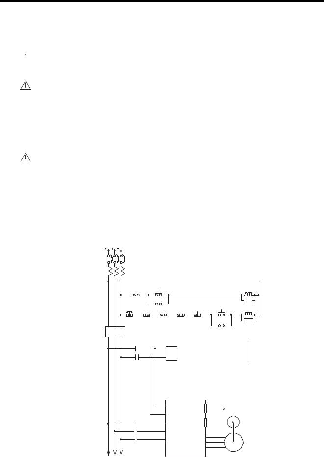
using the ladder programming in the GL120 and GL130. Always construct the emergency stop circuit externally using a relay circuit, as shown in the figure below.
Use an N.C. contact (mechanical contact) in the emergency stop switch. The main power supply to the servo must be cut off by pressing the switch.
Failure to provide an emergency stop circuit as described above, may result in failure of the emergency stop when input circuits fail or cables break, and may cause machine damage or injury.
Control power Control power supply ON |
|
MC1 |
||
supply OFF |
|
|
|
|
|
MC1 |
|
|
Z |
Emergency stop |
MC1 |
Servo OFF Servo ON |
MC2 |
|
ESP-TBOX |
ALM |
MC2 |
Z |
|
|
|
|
Surge absorber |
|
Noise filter
MEMOCON GL120, GL130
MC1 |
Noise filter |
|
|
|
|
||
|
|
|
|
||||
|
|
|
|
|
|
|
|
|
|
|
|
|
|
|
|
|
|
|
|
|
|
|
|
|
|
|
|
|
|
|
|
r SERVOPACK |
Control signal to MC Module |
||
t |
|
||
|
|
||
MC2 |
|
Encoder |
|
r |
|
||
s |
U |
|
|
t |
Servomotor |
||
V |
|||
|
|||
|
W |
|
|
1-11
1 Introduction and Precautions
1.2.5 Application Precautions
|
External Interlocks for the GL120 and GL130 |
WARNING |
Externally connect an interlock to the GL120 and GL130 if there is any chance |
|
that GL120 and GL130 failure could result in bodily harm or equipment damage. |
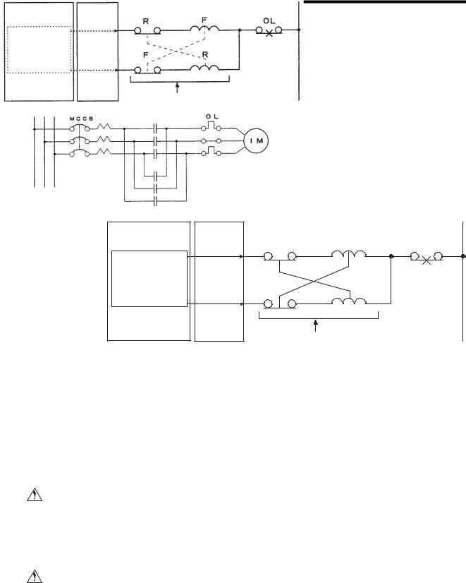
Always use an external interlock system as shown in the following example when reciprocal operations (e.g., forward and reverse directions) are being performed with a motor.
An interlock is generally programmed in the GL120 and GL130 ladder program to ensure that forward and reverse signals are not simultaneously output. An external interlock circuit must also be provided using the auxiliary contacts of electromagnetic contactors.
CPU Module |
Output Module |
Ladder logic program
Output program with an interlock which prohibit simultaneous forward and reverse runs
R |
F |
OL |
|
|
|
Contact of over- |
|
F |
R |
current protection |
|
device. |
|||
|
|
Electric interlock using the auxiliary contacts of electromagnetic contactors
F (Forward run)
Induction motor
|
R (Reverse run) |
CAUTION |
• When inserting or removing an AC I/O Module while the AC power supply is turned |
|
ON, install a safety switch for each Module and always turn this safety switch OFF |
|
to turn OFF the AC power supply to the Module. |
Inserting or removing an AC I/O Module while AC power is being supplied may result in an electric shock at touching the power supply terminals.
CAUTION |
• When using a single-phase AC power supply (100/200 VAC) for driving the loads of |
|
the Relay Contact Output Module, install a safety switch for each Module. Before |
|
inserting or removing the Relay Contact Output Module, always turn this safety |
|
switch OFF to turn OFF the AC power supply to the Module. |
Inserting or removing a Relay Contact Output Module while AC power is being supplied may result in an electric shock at touching the power supply terminals.
1-12
1.2 Precautions
CAUTION |
• The following CPU Modules, Remote I/O Receiver Modules, and MEMOSOFT ver- |
|
||||||
sions are required to use DC 64-point I/O Modules. |
|
|
|
|||||
|
|
|
|
|||||
|
|
Using a version that is not recommended may result in failure or malfunction. |
|
|||||
|
|
|
|
|
|
|
|
|
|
|
Name |
Model |
Model No. |
Version Number |
Location of |
|
|
|
|
|
Name |
|
|
Version Number |
|
|
|
|
CPU Module |
CPU10 |
DDSCR- |
A01 and later |
Module nameplate |
|
|
|
|
(8 kW) |
|
120CPU14200 |
|
|
|
1 |
|
|
|
|
|
|
|
|
|
|
|
CPU Module |
CPU20 |
DDSCR- |
B05 and later |
Module nameplate |
|
|
|
|
(16 kW) |
|
120CPU34100 |
|
|
|
|
|
|
|
|
|
|
|||
|
|
|
|
|
|
|
|
|
|
|
CPU Module |
CPU21 |
DDSCR- |
A01 and later |
Module nameplate |
|
|
|
|
(16 kW) |
|
120CPU34110 |
|
|
|
|
|
|
|
|
|
|
|
|
|
|
|
CPU Module |
CPU30 |
DDSCR- |
B05 and later |
Module nameplate |
|
|
|
|
(32 kW) |
|
120CPU54100 |
|
|
|
|
|
|
|
|
|
|
|
|
|
|
|
CPU Module |
CPU35 |
DDSCR- |
A01 and later |
Module nameplate |
|
|
|
|
(40 kW) |
|
120CPU154110 |
|
|
|
|
|
|
|
|
|
|
|
|
|
|
|
Remote I/O |
RIOR- |
JAMSC- |
A10 and later |
Module nameplate |
|
|
|
|
Receiver |
COAX |
120CRR13100 |
|
|
|
|
|
|
Module |
|
|
|
|
|
|
|
|
|
|
|
|
|
|
|
|
|
MEMOSOFT |
|
FMSGL-AT3 |
1.21 and later |
In the middle at the |
|
|
|
|
|
|
(for English |
|
bottom of the |
|
|
|
|
|
|
DOS) |
|
MEMOSOFT |
|
|
|
|
|
|
|
|
startup screen. |
|
|
|
|
|
|
FMSGL-PP3E |
|
|
|
|
|
|
|
|
|
|
|
|
|
|
|
|
|
(for P120 |
|
|
|
|
|
|
|
|
English version) |
|
|
|
|
|
|
|
|
|
|
|
|
|
* The nameplate is on the right side of the Module.
1-13

1 Introduction and Precautions
1.2.6 Maintenance
1.2.6Maintenance
 CAUTION • Do not disassemble or modify Modules and Mounting Bases.
Failure to observe this caution may result in fire, product failure, or malfunction.
 CAUTION • Do not replace the built-in fuses of the AC 16-point Output Modules.
If the built-in fuses are replaced by anyone other than a Yaskawa-approved technician, a failure or a malfunction may occur in the AC 16-point Output Modules, and the guarantee is void.
 CAUTION • Do not replace the built-in fuses of the DC 8-point Output Modules.
If the built-in fuses are replaced by anyone other than a Yaskawa-approved technician, a failure or malfunction may occur in the DC 8-point Output Modules, and the guarantee is void.
 CAUTION • Do not replace the built-in fuses of the DC 32-point Output Modules.
If the built-in fuses are replaced by anyone other than a Yaskawa-approved technician, a failure or malfunction may occur in the DC 32-point Output Modules, and the guarantee is void.
 CAUTION • Do not replace the built-in fuses of the DC 64-point Output Modules.
If the built-in fuses are replaced by anyone other than a Yaskawa-approved technician, a failure or malfunction may occur in the DC 64-point Output Modules, and the guarantee is void.
 CAUTION • Do not replace the built-in fuses of the Register I/O Modules.
If the built-in fuses are replaced by anyone other than a Yaskawa-approved technician, a failure or malfunction may occur in the Register I/O Modules, and the guarantee is void.
1-14

1.3 Using This Manual
1.3Using This Manual
This manual is written for those who already have a basic knowledge of MEMOCON
PLCs. We recommended reading the MEMOCON GL120, GL130 Hardware User’s
Manual (manual No. SIEZ-C825-20.1) before attempting to read this manual.
• Meaning of Basic Terms |
|
In this manual, the following terms indicate the meanings as described below, |
1 |
|
|
unless otherwise specified. |
|
|
Terms |
Meaning |
Remarks |
|
|
|
|
PLC |
|
Programmable (Logic) Controller |
Does not mean “personal |
|
|
|
computer.” |
|
|
|
|
PP |
|
Programming Panel |
− |
|
|
|
|
GL120, GL130 |
MEMOCON GL120 and MEMOCON GL130 |
− |
|
|
|
Programmable Controllers |
|
|
|
|
|
AC I/O |
AC input |
100-VAC 16-point Input Module |
− |
Module |
Module |
200-VAC 16-point Input Module |
|
|
|
|
|
|
AC output |
100/200-VAC 8-point Output Module |
*1 When the AC load is |
|
Module |
100/200-VAC 16-point Output Module |
applied. |
|
|
Relay Contact 16-point Output Module*1 |
|
DC I/O |
DC input |
12/24-VDC 16-point Input Module |
− |
Module |
Module |
12/24-VDC 32-point Input Module |
|
|
|
12/24-VDC 64-point Input Module |
|
|
|
|
|
|
DC output |
12/24-VDC 8-point Output Module |
*2 When the DC load is |
|
Module |
12/24-VDC 16-point Output Module |
applied. |
|
|
12/24-VDC 32-point Output Module |
|
|
|
12/24-VDC 64-point Output Module |
|
|
|
Relay contact 16-point Output Module*2 |
|
Analog |
Analog |
Analog Input Module (±10V, 4CH) |
− |
I/O |
input Module |
Analog Input Module (0 to 10V, 4CH) |
|
Module |
|
Analog Input Module (4 to 20mA, 4CH) |
|
|
|
|
|
|
Analog |
Analog Output Module (±10V, 2CH) |
− |
|
output Module |
Analog Output Module (0 to 10V, 2CH) |
|
|
|
Analog Output Module (0 to 5V, 2CH) |
|
|
|
Analog Output Module (4 to 20mA, 2CH) |
|
|
|
|
|
Register I/O Module |
Register Input Module |
− |
|
|
|
|
|
|
|
Register Output Module |
|
|
|
|
|
• Description of Technical Terms
The bold technical terms in this manual are briefly explained in the Glossary provided at the bottom of the page. An example is shown below.
Glossary
TERMS |
The following types of terms are described. |
|
|
||
|
• |
Specific sequence control terms required for explanation of functions. |
|
• |
Terms that are specific to programmable controllers and electronic devices. |
1-15
Models and General Specifications
of I/O Modules
2
2
This chapter describes the models and general specifications of I/O
Modules.
2.1 General Specifications - - - - - - - - - - - - - - - - - - - - - - - - - - - 2-2
2.2 I/O Modules - - - - - - - - - - - - - - - - - - - - - - - - - - - - - - - - - - - 2-3
2.2.1 Models of I/O Modules - - - - - - - - - - - - - - - - - - - - - - - 2-3
2.2.2 Overview of I/O Module Specifications - - - - - - - - - - - - 2-5
2.2.3 Using I/O Modules - - - - - - - - - - - - - - - - - - - - - - - - - 2-10
2-1

2Models and General Specifications of I/O Modules
2.1General Specifications
This section gives the general specifications of I/O Modules.
Table 2.1 General Specifications
|
Item |
Specification |
|
|
|
|
|
Environmental |
Ambient Operating Temperature |
0 °C to 60 °C |
|
Conditions |
|
|
|
Ambient Storage Temperature |
-25 C° to 85 °C (excluding battery) |
||
|
|||
|
|
|
|
|
Ambient Operating Humidity |
30 % to 95 % RH (with no condensation) |
|
|
|
|
|
|
Ambient Storage Humidity |
5 % to 95 % RH (with no condensation) |
|
|
|
|
|
|
Pollution Level |
Pollution level 1 (according to JIS B3502) |
|
|
|
|
|
|
Corrosive Gas |
No corrosive gas |
|
|
|
|
|
|
Operating Altitude |
Less than 2,000 m above sea level |
|
|
|
|
|
Mechanical |
Vibration Shock |
10 to 57 Hz with half-amplitude of 0.075mm |
|
Operating |
|
57 to 150 Hz with fixed acceleration of 9.8 m/s2 |
|
Conditions |
|
10 sweep times each in X, Y, and Z directions |
|
|
|
||
|
|
(sweep time: 1 octave/min) (according to JIS B3502) |
|
|
|
|
|
|
Shock Resistance |
Peak acceleration of 147 m/s2 twice for 11 ms in X, Y, |
|
|
|
and Z directions (according to JIS B3502) |
|
|
|
|
|
Electrical |
Noise Resistance |
1,500 V in either normal or common mode with pulse |
|
Operating |
|
widths of 100 ns and 1 µs and rise time of 1 ns (with |
|
Conditions |
|
impulse noise simulator) (according to JIS B3502) |
|
|
|
|
|
Installation |
Ground |
Ground to 100 Ω or less |
|
Requirements |
|
|
|
Configuration |
Building-block, wall-mounted, or DIN track mounted |
||
|
|||
|
|
|
|
|
Cooling Method |
Natural cooling |
|
|
|
|
|
|
Mass |
See specifications for individual I/O Modules. |
|
|
|
|
|
|
External Dimensions |
See specifications for individual I/O Modules. |
|
|
|
|
2-2

2.2 I/O Modules
2.2I/O Modules
This section describes various input modules and output modules.
2.2.1 Models of I/O Modules - - - - - - - - - - - - - - - - - - - - - - - - - - - - - - - - - -2-3
2.2.2 Overview of I/O Module Specifications - - - - - - - - - - - - - - - - - - - - - - -2-5
2.2.3 Using I/O Modules - - - - - - - - - - - - - - - - - - - - - - - - - - - - - - - - - - - - 2-10
2.2.1Models of I/O Modules
Twenty models of I/O Modules are available. |
2 |
|
Table 2.2 I/O Modules |
||
|
Product |
Name |
Model Name |
Model No. |
|
Features |
Number |
|
|
|
|
|
|
of slots |
|
|
|
|
|
|
required |
Digital |
100-VAC |
AC100IN-16P |
JAMSC- |
1) |
Used to input digital signals. |
1 |
Input |
16-point Input |
|
120DAI54300 |
2) |
100VAC, 16 points, 7mA (50Hz) |
|
Modules |
Module |
|
|
|
|
|
|
200-VAC |
AC200IN-16P |
JAMSC- |
1) |
Used to input digital signals. |
1 |
|
16-point Input |
|
120DAI74300 |
2) |
200VAC, 16 points, 7mA (50Hz) |
|
|
Module |
|
|
|
|
|
|
|
|
|
|
|
|
|
12/24-VDC |
DC24IN-16P |
JAMSC- |
1) |
Used to input digital signals. |
1 |
|
16-point Input |
|
120DDI34300 |
2) |
12/24VDC, 16 points, 4mA (12VDC), 8mA |
|
|
Module |
|
|
|
(24VDC) |
|
|
|
|
|
|
|
|
|
12/24-VDC |
DC24IN-32P |
JAMSC- |
1) |
Used to input digital signals. |
1 |
|
32-point Input |
|
120DDI35400 |
2) |
12/24VDC, 32 points, 2mA (12VDC), 4mA |
|
|
Module |
|
|
|
(24VDC) |
|
|
12/24-VDC |
DC24IN-64P |
JAMSC- |
1) |
Used to input digital signals. |
1 |
|
64-point Input |
|
120DDI36400 |
2) |
12/24VDC, 64 points, 2mA (12VDC), 4mA |
|
|
Module |
|
|
|
(24VDC) |
|
|
|
|
|
|
|
|
Analog |
Analog Input |
A/D-VOL- |
JAMSC- |
1) |
Used to input analog signals. |
1 |
Input |
Module (±10V, |
4CH |
120AVI02000 |
2) |
-10 to 10V, 4 channels |
|
Modules |
4 channels) |
|
|
|
|
|
|
Analog Input |
A/D 0-10V |
JAMSC- |
1) |
Used to input analog signals. |
1 |
|
Module (0 to |
4CH |
120AVI02100 |
2) |
0 to 10V, 4 channels |
|
|
10V, 4 chan- |
|
|
|
|
|
|
nels) |
|
|
|
|
|
|
Analog Input |
A/D-CUR- |
JAMSC- |
1) |
Used to input analog signals. |
1 |
|
Module (4 to |
4CH |
120ACI02000 |
2) |
4 to 20mA/1 to 5V, 4 channels |
|
|
20mA, 4 chan- |
|
|
|
|
|
|
nels) |
|
|
|
|
|
Digital |
100/200-VAC |
ACOUT-8P |
JAMSC- |
1) |
Used to output digital signals. |
1 |
Output |
8-point |
|
120DAO83000 |
2) |
100/200VAC, 8 points, 1.0 A/point |
|
Modules |
Output Module |
|
|
|
|
|
|
100/200-VAC |
ACOUT-16P |
JAMSC- |
1) |
Used to output digital signals. |
1 |
|
16-point |
|
120DAO84300 |
2) |
100/200VAC, 16 points, 0.3 A/point |
|
|
Output Module |
|
|
|
|
|
|
|
|
|
|
|
|
|
12/24-VDC 8- |
DC24OUT-8P |
JAMSC- |
1) |
Used to output digital signals. |
1 |
|
point Output |
|
120DDO33000 |
2) |
12/24VDC, 8 points, sourcing/sinking |
|
|
Module |
|
|
|
outputs, 2.0 A/point |
|
|
12/24-VDC |
DC24OUT- |
JAMSC- |
1) |
Used to output digital signals. |
1 |
|
16-point Out- |
16PSN |
120DDO34310 |
2) |
12/24VDC, 16 points, sinking outputs, 0.5 |
|
|
put Module |
|
|
|
A/point, 1.0 A/4points |
|
|
(sinking) |
|
|
|
|
|
2-3

2 Models and General Specifications of I/O Modules
2.2.1 Models of I/O Modules
Table 2.2 I/O Modules
Product |
Name |
Model Name |
Model No. |
|
Features |
Number |
|
|
|
|
|
|
of slots |
|
|
|
|
|
|
required |
Digital |
12/24-VDC |
DC24OUT- |
JAMSC- |
1) |
Used to output digital signals. |
1 |
Output |
16-point Out- |
16PSR |
120DDO34320 |
2) |
12/24VDC, 16 points, sourcing outputs, |
|
Modules |
put Module |
|
|
|
0.5 A/point, 1.0 A/4points |
|
|
(sourcing) |
|
|
|
|
|
|
12/24-VDC |
DC24OUT- |
JAMSC- |
1) |
Used to output digital signals. |
1 |
|
32-point Out- |
32PSN |
120DDO35410 |
2) |
12/24VDC, 32 points, sinking outputs, 0.3 |
|
|
put Module |
|
|
|
A/point, 0.4 A/4points |
|
|
(sinking) |
|
|
|
|
|
|
12/24-VDC |
DC24OUT- |
JAMSC- |
1) |
Used to output digital signals. |
1 |
|
64-point Out- |
64PSN |
120DDO36410 |
2) |
12/24VDC, 64 points, sinking outputs, 0.1 |
|
|
put Module |
|
|
|
A/point |
|
|
(sinking) |
|
|
|
|
|
|
Relay Contact |
RELAY-16P |
JAMSC- |
1) |
Used to output digital signals. |
1 |
|
16-point Out- |
|
120DRA84300 |
2) |
Relay contacts, 16 points, 1.0 A/point |
|
|
put Module |
|
|
|
|
|
Analog |
Analog Out- |
D/A-VOL-2CH |
JAMSC- |
1) |
Used to output analog signals. |
1 |
Output |
put Module |
|
120AVO01000 |
2) |
-10 to 10V, 2 channels |
|
Modules |
(±10V, 2 chan- |
|
|
|
|
|
|
nels) |
|
|
|
|
|
|
Analog Out- |
D/A 0-10V 2CH |
JAMSC- |
1) |
Used to output analog signals. |
1 |
|
put Module |
|
120AVO01100 |
2) |
0 to 10V, 2 channels |
|
|
(0 to 10V, 2 |
|
|
|
|
|
|
channels) |
|
|
|
|
|
|
Analog Out- |
D/A 0-5V 2CH |
JAMSC- |
1) |
Used to output analog signals. |
1 |
|
put Module |
|
120AVO01200 |
2) |
0 to 5V, 2 channels |
|
|
(0 to 5V, 2 |
|
|
|
|
|
|
channels) |
|
|
|
|
|
|
Analog Out- |
D/A-CUR- 2CH |
JAMSC- |
1) |
Used to output analog signals. |
1 |
|
put Module |
|
120ACO01000 |
2) |
4 to 20mA, 2 channels |
|
|
(4 to 20mA, 2 |
|
|
|
|
|
|
channels) |
|
|
|
|
|
Special |
Register Input |
REGISTER-IN |
JAMSC- |
1) |
Used to input a maximum of 8 sets (8 |
1 |
Purpose |
Module |
|
120RDI34410 |
|
channel) or 16 sets (16 channel) of 16-bit |
|
Modules |
|
|
|
|
or BCD 4-digit values. |
|
|
|
|
|
2) |
The data input cycle can be selected: |
|
|
|
|
|
|
For 8 channels: 10/32/64/192/320 ms |
|
|
|
|
|
|
For 16 channels: 20/64/128/384/640 ms |
|
|
Register Out- |
REGISTER- |
JAMSC- |
1) |
Used to output a maximum of 8 sets (8 |
1 |
|
put Module |
OUT |
120RDO34410 |
|
channel) or 16 sets (16 channel) of 16-bit |
|
|
|
|
|
|
or BCD 4-digit values. |
|
|
|
|
|
2) |
Select the data output cycle. |
|
|
|
|
|
|
For 8-channel: 32/64/192/320 ms |
|
|
|
|
|
|
For 16-channel: 64/128/640 ms |
|
Note: The 64-point I/O Modules are limited to versions for the CPU Module, remote I/O
Receiver Module and MEMOSOFT. Refer to 2.2.3 Using I/O Modules for details.
2-4

2.2 I/O Modules
2.2.2 |
Overview of I/O Module Specifications |
|
|
1) Digital Input Modules |
|
|
a) Function |
|
|
A Digital Input Module converts the digital signals coming from pushbutton switches, |
|
|
limit switches, and digital switches into signals of appropriate voltage for PLC inter- |
|
|
nal processing. The converted digital signals are stored by the CPU Module as input |
|
|
relays and input registers in state memory. |
|
|
b) Specifications |
|
|
The following table shows the main specifications of Digital Input Modules. |
2 |
|
|
|
|
Table 2.3 Main Specifications of Digital Input Modules |
|
|
|
Name |
Model |
Model No. |
Rated |
Rated |
Input |
Input |
Num- |
Internal |
Maxi- |
Hot |
|
Name |
|
Volt- |
Current |
Imped- |
Delay |
ber of |
Current Con- |
mum |
Swap- |
|
|
|
age |
|
ance |
Times |
inputs |
sumption |
Heat- |
ping |
|
|
|
|
|
|
|
|
|
ing |
|
|
|
|
|
|
|
|
|
|
Value |
|
100-VAC |
AC100IN- |
JAMSC- |
100 |
7 mA |
14.3 kΩ |
OFF→ON: |
16 |
With all points |
2.0 W |
Per- |
16-point |
16P |
120DAI54 |
VAC |
(50Hz) |
(50 Hz) |
Max. 20 ms |
|
ON: 90 mA |
|
mitted |
Input |
|
300 |
|
|
12.5 kΩ |
ON→OFF: |
|
|
|
|
Module |
|
|
|
|
(60 Hz) |
Max. 35 ms |
|
|
|
|
|
|
|
|
|
|
|
|
|
|
|
200-VAC |
AC200IN- |
JAMSC- |
200 |
7 mA |
28.6 kΩ |
OFF→ON: |
16 |
With all points |
3.5 W |
Per- |
16-point |
16P |
120DAI74 |
VAC |
(50Hz) |
(50 Hz) |
Max. 20 ms |
|
ON: 90 mA |
|
mitted |
Input |
|
300 |
|
|
23.1 kΩ |
ON→OFF: |
|
|
|
|
Module |
|
|
|
|
(60 Hz) |
Max. 35 ms |
|
|
|
|
|
|
|
|
|
|
|
|
|
|
|
12/24- |
DC24IN- |
JAMSC- |
12/24 |
4 mA |
3.0 kΩ |
OFF→ON: |
16 |
With all points |
3.7 W |
Per- |
VDC 16- |
16P |
120DDI34 |
VDC |
(12 VDC) |
|
Max. 5 ms |
|
ON: 100 mA |
|
mitted |
point Input |
|
300 |
|
8 mA |
|
ON→OFF: |
|
|
|
|
Module |
|
|
|
(24 VDC) |
|
Max. 5 ms |
|
|
|
|
|
|
|
|
|
|
|
|
|
|
|
12/24- |
DC24IN- |
JAMSC- |
12/24 |
2 mA |
5.6 kΩ |
OFF→ON: |
32 |
With all points |
3.6 W |
Per- |
VDC 32- |
32P |
120DDI35 |
VDC |
(12 VDC) |
|
Max. 5 ms |
|
ON: 80 mA |
|
mitted |
point Input |
|
400 |
|
4 mA |
|
ON→OFF: |
|
|
|
|
Module |
|
|
|
(24 VDC) |
|
Max. 5 ms |
|
|
|
|
|
|
|
|
|
|
|
|
|
|
|
12/24- |
DC24IN- |
JAMSC- |
12/24 |
2 mA |
5.6 kΩ |
OFF→ON: |
64 |
With all points |
7.0 W |
Per- |
VDC 64- |
64P |
120DDI36 |
VDC |
(12 VDC) |
|
Max. 5 ms |
|
ON: 100 mA |
|
mitted |
point Input |
|
400 |
|
4 mA |
|
ON→OFF: |
|
|
|
|
Module |
|
|
|
(24 VDC) |
|
Max. 5 ms |
|
|
|
|
|
|
|
|
|
|
|
|
|
|
|
Other Specifications |
|
|
|
|
|
|
|
|
|
|
|
|
|
|
|
|
|
|
|
|
|
1) Slots required: 1 |
|
|
|
|
|
|
|
|
|
|
2) Width: 40.3 mm |
Height: 130 mm |
Depth: 103.9 mm |
|
|
|
|
|
|||
3)Approx. mass
16-point Input Module: 250 g
32-point Input Module: 250 g
64-point Input Module: 300 g
4)Field connections
16-point Input Module: terminal block
32-point Input Module: connector
64-point Input Module: connector
5)Number of points per common
16-point Input Module: 8 points per common
32-point Input Module: 16 points per common
64-point Input Module: 16 points per common
2-5

2 Models and General Specifications of I/O Modules
2.2.2Overview of I/O Module Specifications
2)Analog Input Modules
a)Function
An Analog Input Module converts the analog signals coming from weight sensors, temperature sensors, etc., into numeric data appropriate for PLC internal processing. The converted numeric data is stored by the CPU Module as the input registers in state memory.
b)Specifications
The following table shows the main specifications of the Analog Input Modules.
Table 2.4 Main Specifications of Analog Input Modules
Name |
Model |
Model |
Input |
Overall |
Resolution |
Input |
Num- |
Internal |
Maxi- |
Hot |
|
Name |
No. |
Signal |
Accuracy |
and Data |
Impedance |
ber of |
Current |
mum |
Swap- |
|
|
|
Range |
|
Types |
|
Chan- |
Con- |
Heat- |
ping |
|
|
|
|
|
|
|
nels |
sump- |
ing |
|
|
|
|
|
|
|
|
|
tion |
Value |
|
|
|
|
|
|
|
|
|
|
|
|
|
|
|
|
|
|
|
|
|
|
|
Analog |
A/D- |
JAMSC- |
-10 to |
±0.5% F.S. |
0 to 4000 |
1 MΩ min. |
4 |
450 |
2.3 W |
Per- |
Input |
VOL- |
120AVI |
+10 V |
(25°C) |
mode: 12 bits, |
|
|
mA |
|
mitted |
Module |
4CH |
02000 |
|
|
binary between |
|
|
|
|
|
(±10 V, 4 |
|
|
|
|
0 and 4000 |
|
|
|
|
|
channels) |
|
|
|
±1.0% F.S. |
± 2000 mode: |
|
|
|
|
|
|
|
|
|
|
|
|
|
|
||
|
|
|
|
(0 to 60°C) |
12 bits, 2’s |
|
|
|
|
|
|
|
|
|
|
complement |
|
|
|
|
|
|
|
|
|
|
between -2000 |
|
|
|
|
|
|
|
|
|
|
and +2000 |
|
|
|
|
|
|
|
|
|
|
|
|
|
|
|
|
Analog |
A/D |
JAMSC- |
0 to |
±0.5% F.S. |
12 bits, binary |
1 MΩ min. |
4 |
450 |
2.3 W |
Per- |
Input |
0-10V |
120AVI |
+10 V |
(25°C) |
between 0 and |
|
|
mA |
|
mitted |
Module |
4CH |
02100 |
|
±1.0% F.S. |
4000 |
|
|
|
|
|
(0 to |
|
|
|
(0 to 60°C) |
|
|
|
|
|
|
10 V, |
|
|
|
|
|
|
|
|
|
|
4 chan- |
|
|
|
|
|
|
|
|
|
|
nels) |
|
|
|
|
|
|
|
|
|
|
|
|
|
|
|
|
|
|
|
|
|
Analog |
A/D- |
JAMSC- |
Current |
±0.5% F.S. |
12 bits, binary |
Current |
4 |
450 |
2.3 W |
Per- |
Input |
CUR- |
120ACI |
input: |
(25 °C) |
between 0 and |
input: 250 Ω |
|
mA |
|
mitted |
Module (4 |
4CH |
02000 |
4 to 20 |
±1.0% F.S. |
4000 |
voltage |
|
|
|
|
to 20 mA, |
|
|
mA |
(0 to 60°C) |
|
input: 1 MΩ |
|
|
|
|
4 chan- |
|
|
Voltage |
|
|
min. |
|
|
|
|
nels) |
|
|
input: |
|
|
|
|
|
|
|
|
|
|
1 to 5 V |
|
|
|
|
|
|
|
|
|
|
|
|
|
|
|
|
|
|
Other Specifications |
|
|
|
|
|
|
|
|
|
|
|
|
|
|
|
|
|
|
|
|
|
1)Slots required: 1
2)Approx. mass: 300 g
3) |
Width: 40.3 mm |
Height: 130 mm |
Depth: 103.9 mm |
4) |
Field connections: Terminal block |
|
|
2-6

2.2 I/O Modules
3) Digital Output Modules a) Function
A Digital Output Module converts the numeric data stored in output registers or the ON/OFF state of the output coil in the state memory of the CPU Module into digital signals for control of indicators, electromagnetic switches, relays, solenoid valves, numeric indicators, etc.
b)Specifications
The following table shows the main specifications of Digital Output Modules.
|
|
Table 2.5 Main Specifications of Digital Output Modules |
|
|
|
|
2 |
||||||
Name |
Model |
Model No. |
Rated |
Load |
Remarks |
Output |
Num |
|
Internal |
Maxi- |
Hot |
|
|
|
|||||||||||||
|
Name |
|
Volt- |
Current |
|
Delay |
ber |
|
Current Con- |
mum |
Swap |
|
|
|
|
|
age |
|
|
Times |
of |
|
sumption |
Heat- |
ping |
|
|
|
|
|
|
|
|
|
Out- |
|
|
ing |
|
|
|
|
|
|
|
|
|
|
puts |
|
|
Value |
|
|
|
100/200- |
ACOUT |
JAMSC- |
100/ |
1.0 A/ |
Unpro- |
OFF→ON: |
8 |
|
With all |
9.0 W |
Per- |
|
|
VAC |
-8P |
120DAO83 |
200 |
point |
tected |
Max. 5 ms |
|
|
points ON: |
|
mit- |
|
|
8-point |
|
000 |
VAC |
|
outputs |
ON→OFF: |
|
|
150 mA |
|
ted |
|
|
Output |
|
|
|
|
|
1/2 cycle + |
|
|
|
|
|
|
|
Module |
|
|
|
|
|
5 ms max. |
|
|
|
|
|
|
|
100/200- |
ACOUT |
JAMSC- |
100/ |
0.6 A/ |
Unpro- |
OFF→ON: |
16 |
|
With all |
5.5 W |
Per- |
|
|
VAC |
-16P |
120DAO84 |
200 |
point |
tected |
Max. 5 ms |
|
|
points ON: |
|
mit- |
|
|
16-point |
|
300 |
VAC |
|
outputs |
ON→OFF: |
|
|
300 mA |
|
ted |
|
|
Output |
|
|
|
|
|
1/2 cycle + |
|
|
|
|
|
|
|
Module |
|
|
|
|
|
5 ms max. |
|
|
|
|
|
|
|
12/24-VDC |
DC24O |
JAMSC- |
12/24 |
2.0 A/ |
Short-cir- |
OFF→ON: |
8 |
|
With all |
1.6 W |
Per- |
|
|
8-point |
UT-8P |
120DDO33 |
VDC |
point |
cuit pro- |
Max. 3 ms |
|
|
points ON: |
|
mit- |
|
|
Output |
|
000 |
|
|
tection |
ON→OFF: |
|
|
220 mA |
|
ted |
|
|
Module |
|
|
|
|
Sourcing/ |
Max. 5 ms |
|
|
|
|
|
|
|
|
|
|
|
|
sinking |
|
|
|
|
|
|
|
|
|
|
|
|
|
outputs |
|
|
|
|
|
|
|
|
12/24-VDC |
DC24O |
JAMSC- |
12/24 |
0.5 A/ |
Unpro- |
OFF→ON: |
16 |
|
With all |
7.1 W |
Per- |
|
|
16-point |
UT- |
120DDO34 |
VDC |
point, |
tected |
Max. 1 ms |
|
|
points ON: |
|
mit- |
|
|
Output |
16PSN |
310 |
|
1.0 A/ |
outputs |
ON→OFF: |
|
|
220 mA |
|
ted |
|
|
Module |
|
|
|
4 points |
Sinking |
Max. 1 ms |
|
|
|
|
|
|
|
(sinking) |
|
|
|
|
outputs |
|
|
|
|
|
|
|
|
|
|
|
|
|
|
|
|
|
|
|
|
|
|
12/24-VDC |
DC24O |
JAMSC- |
12/24 |
0.5 A/ |
Unpro- |
OFF→ON: |
16 |
|
With all |
7.5 W |
Per- |
|
|
16-point |
UT- |
120DDO34 |
VDC |
point, |
tected |
Max. 1 ms |
|
|
points ON: |
|
mit- |
|
|
Output |
16PSR |
320 |
|
1.0 A/ |
outputs |
ON→OFF: |
|
|
300 mA |
|
ted |
|
|
Module |
|
|
|
4 points |
Sourcing |
Max. 1 ms |
|
|
|
|
|
|
|
(sourcing) |
|
|
|
|
outputs |
|
|
|
|
|
|
|
|
|
|
|
|
|
|
|
|
|
|
|
|
|
|
12/24-VDC |
DC24O |
JAMSC- |
12/24 |
0.3 A/ |
Unpro- |
OFF→ON: |
32 |
|
With all |
6.5 W |
Per- |
|
|
32-point |
UT- |
120DDO35 |
VDC |
point, |
tected |
Max. 1 ms |
|
|
points ON: |
|
mit- |
|
|
Output |
32PSN |
410 |
|
0.4 A/ |
outputs |
ON→OFF: |
|
|
330 mA |
|
ted |
|
|
Module |
|
|
|
4 points |
Sinking |
Max. 1 ms |
|
|
|
|
|
|
|
(sinking) |
|
|
|
|
outputs |
|
|
|
|
|
|
|
|
|
|
|
|
|
|
|
|
|
|
|
|
|
|
12/24-VDC |
DC24O |
JAMSC- |
12/24 |
0.1 A/ |
Unpro- |
OFF→ON: |
64 |
|
With all |
13.0 W |
Per- |
|
|
64-point |
UT- |
120DDO36 |
VDC |
point |
tected |
Max. 1 ms |
|
|
points ON: |
|
mit- |
|
|
Output |
64PSN |
410 |
|
|
output |
ON→OFF: |
|
|
650 mA |
|
ted |
|
|
Module |
|
|
|
|
Sinking |
Max. 1 ms |
|
|
|
|
|
|
|
(sinking) |
|
|
|
|
outputs |
|
|
|
|
|
|
|
|
|
|
|
|
|
|
|
|
|
|
|
|
|
|
Relay con- |
RELAY- |
JAMSC- |
Relay |
1.0 A/ |
Unpro- |
OFF→ON: |
16 |
|
With all |
3.1 W |
Per- |
|
|
tact |
16P |
120DRA84 |
contact |
point |
tected |
Max. 10 ms |
|
|
points ON: |
|
mit- |
|
|
16-point |
|
300 |
|
|
outputs |
ON→OFF: |
|
|
610 mA |
|
ted |
|
|
Output |
|
|
|
|
|
Max. 15 ms |
|
|
|
|
|
|
|
Module |
|
|
|
|
|
|
|
|
|
|
|
|
|
2-7

2 Models and General Specifications of I/O Modules
2.2.2 Overview of I/O Module Specifications
Table 2.5 Main Specifications of Digital Output Modules
|
Name |
Model |
Model No. |
Rated |
Load |
Remarks |
Output |
Num |
Internal |
Maxi- |
Hot |
|
|
Name |
|
Volt- |
Current |
|
Delay |
ber |
Current Con- |
mum |
Swap |
|
|
|
|
age |
|
|
Times |
of |
sumption |
Heat- |
ping |
|
|
|
|
|
|
|
|
Out- |
|
ing |
|
|
|
|
|
|
|
|
|
puts |
|
Value |
|
Other Specifications |
|
|
|
|
|
|
|
|
|
||
|
|
|
|
|
|
|
|
|
|
|
|
1) |
Slots required: 1 |
|
|
|
|
|
|
|
|
|
|
2) |
Width: 40.3 mm |
Height: 130 mm |
Depth: 103.9 mm |
|
|
|
|
|
|||
3) |
Approx. mass |
|
|
|
|
|
|
|
|
|
|
|
AC Output Module: 300 g |
|
|
|
|
|
|
|
|||
|
DC Output Module (8-point, 16-point, 32-point): 250 g |
|
|
|
|
|
|||||
|
DC Output Module (64-point): 300 g |
|
|
|
|
|
|
|
|||
|
Relay Contact Output Module: 300 g |
|
|
|
|
|
|
|
|||
4) |
Field connections |
|
|
|
|
|
|
|
|
|
|
|
8-point Output Module: terminal block |
|
|
|
|
|
|
|
|||
16-point Output Module: terminal block
32-point Output Module: connector
64-point Output Module: connector
Relay Contact Output Module: terminal block 5) Number of points per common
8-point Output Module: Independent outputs
16-point Output Module: 8 points per common
32-point Output Module: 16 points per common
64-point Output Module: 16 points per common Relay Contact Output Module: 8 points per common
2-8

2.2 I/O Modules
4) Analog Output Module a) Function
An Analog Output Module converts the numeric data stored in output registers in the state memory of the CPU Module into analog signals for control of heaters, pumps, PID adjusters, inverters, etc.
b)Specifications
The following table shows the main specifications of the Analog Output Modules.
|
|
|
Table 2.6 Main Specifications of Analog Output Modules |
|
|
|
|
|
|||||
|
|
|
|
|
|
|
|
|
|
|
|
|
2 |
Name |
Model |
Model |
|
Output |
Overall |
Resolution and |
Maxi- |
Num- |
Inter- |
Maxi- |
Hot |
||
|
Name |
No. |
|
Signal |
Accuracy |
Data Types |
mum |
ber of |
nal Cur- |
mum |
Swap- |
||
|
|
|
|
Range |
|
|
Permis- |
Chan- |
rent |
Heat- |
ping |
|
|
|
|
|
|
|
|
||||||||
|
|
|
|
|
|
|
sible |
nels |
Con- |
ing |
|
|
|
|
|
|
|
|
|
|
Load |
|
sump- |
Value |
|
|
|
|
|
|
|
|
|
|
|
tion |
|
|
|
||
|
|
|
|
|
|
|
Current |
|
|
|
|
|
|
|
|
|
|
|
|
|
|
|
|
|
|
|
|
|
|
|
|
|
|
|
|
|
|
|
|
|
|
Analog |
D/A- |
JAMSC- |
|
-10 to |
±0.2% F.S. |
0 to 4000 mode: |
±5 mA, |
2 |
400 |
2.0 W |
Permit- |
|
|
Output |
VOL- |
120AVO |
|
+10 V |
(25 °C) |
12 bits, binary |
2 kΩ |
|
mA |
|
ted |
|
|
Module |
2CH |
01000 |
|
|
|
between 0 and |
min. |
|
|
|
|
|
|
(±10 V, 2 |
|
|
|
|
|
4000 |
|
|
|
|
|
|
|
channels) |
|
|
|
|
±0.5% F.S. |
±2000 mode: 12 |
|
|
|
|
|
|
|
|
|
|
|
|
|
|
|
|
|
|
|
||
|
|
|
|
|
(0 to |
bits, 2’s comple- |
|
|
|
|
|
|
|
|
|
|
|
|
60 °C) |
ments between |
|
|
|
|
|
|
|
|
|
|
|
|
|
-2000 and |
|
|
|
|
|
|
|
|
|
|
|
|
|
+2000 |
|
|
|
|
|
|
|
|
|
|
|
|
|
|
|
|
|
|
|
|
|
Analog |
D/A |
JAMSC- |
|
0 to +10 |
±0.2% F.S. |
12 bits, binary |
5 mA, |
2 |
400 |
2.0 W |
Permit- |
|
|
Output |
0-10V |
120AVO |
|
V |
(25 °C) |
between 0 and |
2 kΩ |
|
mA |
|
ted |
|
|
Module (0 |
2CH |
01100 |
|
|
±0.5% F.S. |
4000 |
min. |
|
|
|
|
|
|
to 10 V, 2 |
|
|
|
|
(0 to 60 °C) |
|
|
|
|
|
|
|
|
channels) |
|
|
|
|
|
|
|
|
|
|
|
|
|
|
|
|
|
|
|
|
|
|
|
|
|
|
|
Analog |
D/A |
JAMSC- |
|
0 to +5 |
±0.2% F.S. |
12 bits, binary |
2.5 mA, |
2 |
400 |
2.0 W |
Permit- |
|
|
Output |
0-5V |
120AVO |
|
V |
(25 °C) |
between 0 and |
2 kΩ |
|
mA |
|
ted |
|
|
Module (0 |
2CH |
01200 |
|
|
±0.5% F.S. |
4000 |
min. |
|
|
|
|
|
|
to 5 V, 2 |
|
|
|
|
(0 to 60 °C) |
|
|
|
|
|
|
|
|
channels) |
|
|
|
|
|
|
|
|
|
|
|
|
|
|
|
|
|
|
|
|
|
|
|
|
|
|
|
Analog |
D/A- |
JAMSC- |
|
4 to 20 |
±0.2% F.S. |
12 bits, binary |
550 Ω |
2 |
500 |
2.5 W |
Permit- |
|
|
Output |
CUR- |
120AC |
|
mA |
(25 °C) |
between 0 and |
max. |
|
mA |
|
ted |
|
|
Module (4 |
2CH |
O01000 |
|
|
±0.5% F.S. |
4000 |
|
|
|
|
|
|
|
to 20 mA, |
|
|
|
|
(0 to 60 °C) |
|
|
|
|
|
|
|
|
2 chan- |
|
|
|
|
|
|
|
|
|
|
|
|
|
nels) |
|
|
|
|
|
|
|
|
|
|
|
|
|
|
|
|
|
|
|
|
|
|
|
|
|
|
|
Other Specifications |
|
|
|
|
|
|
|
|
|
|
|
|
|
|
|
|
|
|
|
|
|
|
|
|
|
|
|
1)Slots required: 1
2)Approx. mass : 350 g
3) |
Width: 40.3 mm |
Height: 130 mm |
Depth: 103.9 mm |
4) |
Field connection: Terminal block |
|
|
2-9

2 Models and General Specifications of I/O Modules
2.2.3Using I/O Modules
2.2.3Using I/O Modules
1)Installation Location of I/O Modules
(1)I/O Modules can be mounted to any slot of the Mounting Base of any Rack. Each I/O Module occupies one slot.
(2)The following diagram shows an example on where to mount I/O Modules.
 EXAMPLE
1 |
2 |
|
3 |
|
4 |
|
5 |
|
|
6 |
|
7 |
8 |
|
9 |
|
10 |
11 |
12 |
|
|
|
Slot No. |
||||||||||||||
|
|
|
|
|
|
|
|
|
|
|
|||||||||||||||||||||||||||
PS10 |
|
|
|
|
|
|
|
|
DI |
|
DI |
|
DO |
|
MC20 |
|
|
|
|
|
|
|
|
|
|
|
|
Rack 1 (CPU Rack) |
|||||||||
|
|
CPU30 |
|
|
|
|
|
MC20 |
|
EXP |
|
|
|
||||||||||||||||||||||||
|
|
|
|
|
|
P |
|
M |
|
|
|
|
|
|
|
|
|
|
|
|
|
|
|
|
|
|
|
|
|
|
|
|
|
MB12 |
|||
|
|
|
|
|
|
|
|
|
|
|
|
|
|
|
|
|
|
|
|
|
|
|
|
|
|
|
|
|
|
||||||||
|
|
|
|
|
|
|
|
|
|
|
|
|
|
|
|
|
|
|
|
|
|
|
|
|
|
|
|
|
|
|
|
|
|
|
|
|
|
|
|
|
|
|
|
|
|
|
|
|
|
|
|
|
|
|
|
|
|
|
|
|
|
|
|
|
|
|
|
|
|
W0100-02 |
|||||
1 |
2 |
3 |
4 |
5 |
|
6 |
|
7 |
8 |
|
9 |
|
10 |
|
11 |
|
12 |
|
|
||||||||||||||||||
|
|
|
|
|
|
|
|
|
|
|
|
|
|
|
|
|
|
|
|
|
|
|
|
|
|
|
|
|
|
|
|
|
|
|
|
Rack 2 |
|
|
|
|
|
|
|
|
|
|
|
|
|
|
|
|
|
|
|
|
|
|
|
|
|
|
|
|
|
|
|
|
|
|
|
|
|
||
PS |
|
DI |
|
DI |
|
DI |
|
DI |
|
DI |
|
DI |
|
DO |
|
DO |
|
|
DO |
|
|
DO |
|
EXP |
|
|
|
||||||||||
05 |
|
|
|
|
|
|
|
|
|
|
|
|
|
|
|
|
|
|
|
|
|
|
|
|
|
|
|
|
|
|
|
|
|
|
|
MB12 |
|
|
|
|
|
|
|
|
|
|
|
|
|
|
|
|
|
|
|
|
|
|
|
|
|
|
|
|
|
|
|
|
|
|
|
|
|
||
|
|
|
|
|
|
|
|
|
|
|
|
|
|
|
|
|
|
|
|
|
|
|
|
|
|
|
|
|
|
|
|
|
|
|
|
|
|
PS10: |
Power Supply Module (7 A) |
|
|
|
MC20: |
|
4-axis Motion Module |
||||||||||||||||||||||||||||||
PS05: |
Power Supply Module (3 A) |
|
|
|
EXP: |
|
Expander Module |
||||||||||||||||||||||||||||||
CPU30: CPU Module (32 kW) |
|
|
|
|
|
|
|
MB12: |
|
12 slot Mounting Base |
|||||||||||||||||||||||||||
|
|
|
|
|
W0100-02: Rack-to-rack I/O Cable (0.2 m) |
||||||||||||||||||||||||||||||||
DI: |
|
|
|
12/24-VDC 16-point Input Module |
|||||||||||||||||||||||||||||||||
|
|
|
|
|
|
|
|
|
|
|
|
|
|
|
|
|
|
|
|
|
|||||||||||||||||
DO: |
|
|
|
12/24-VDC 16-point Output Module |
|
|
|
|
|
|
|
|
|
|
|
|
|
|
|
|
|||||||||||||||||
Fig. 2.1 Example of Mounting I/O Modules
2) Versions Supporting 64-point I/O Modules
The following CPU Modules, Remote I/O Receiver Modules, and MEMOSOFT versions are required to user 64-point I/O Modules.
Table 2.7 Versions Supporting 64-point I/O Modules
Name |
Model |
Model No. |
Version Number |
Location of Ver- |
|
Name |
|
|
sion Number |
|
|
|
|
|
CPU Module |
CPU10 |
DDSCR-120CPU14200 |
A01 and later |
Module nameplate |
(8 kw) |
|
|
|
|
|
|
|
|
|
CPU Module |
CPU20 |
DDSCR-120CPU34100 |
B05 and later |
Module nameplate |
(16 kw) |
|
|
|
|
|
|
|
|
|
CPU Module |
CPU21 |
DDSCR-120CPU34110 |
A01 and later |
Module nameplate |
(16 kw) |
|
|
|
|
|
|
|
|
|
CPU Module |
CPU30 |
DDSCR-120CPU54100 |
B05 and later |
Module nameplate |
(32 kw) |
|
|
|
|
|
|
|
|
|
CPU Module |
CPU35 |
DDSCR-120CPU54110 |
A01 and later |
Module nameplate |
(40 kw) |
|
|
|
|
|
|
|
|
|
Remote I/O |
RIOR- |
DDSCR-120CRR13100 |
A10 and later |
Module nameplate |
Receiver |
COAX |
|
|
|
Module |
|
|
|
|
|
|
|
|
|
MEMOSOFT |
|
FMSGL-AT3 |
1.21 and later |
In the middle at the |
|
|
(for English DOS) |
|
bottom of the |
|
|
|
|
MEMOSOFT |
|
|
FMSGL-PP3E |
|
|
|
|
|
startup screen |
|
|
|
(for P120 English version) |
|
|
|
|
|
|
|
|
|
|
|
|
Note: The nameplate is on the right side of the Module. |
|
|||
2-10
Loading...