


 Loading...
YASKAWA SGD7S, SGD7W, SGD7C, SGM7M, SGM7J Selection Manual
...-7-Series AC Servo Drive
Peripheral Device
Selection Manual
Applicable SERVOPACK Model: SGD7S, SGD7W, SGD7C
Applicable Rotary Servomotor Model: SGM7M, SGM7J, SGM7A, SGM7P, SGM7G, SGMMV Applicable Direct Drive Servomotor Model: SGM7D, SGM7E, SGM7F, SGMCV, SGMCS Applicable Linear Servomotor Model: SGLG, SGLF, SGLT
Peripheral Devices
and System Configurations
Cables and User-Assembled Wiring
Materials for SGM7M Rotary Servomotors
Cables and User-Assembled Wiring
Materials for SGM7J Rotary Servomotors
Cables and User-Assembled Wiring
Materials for SGM7A Rotary Servomotors
Cables and User-Assembled Wiring
Materials for SGM7P Rotary Servomotors
Cables and User-Assembled Wiring
Materials for SGM7G Rotary Servomotors
Cables and User-Assembled Wiring
Materials for SGMMV Rotary Servomotors
Cables and User-Assembled Wiring
Materials for Direct Drive Servomotors
Cables and User-Assembled Wiring
Materials for Linear Servomotors
Cables and User-Assembled Wiring
Materials for SERVOPACKs
Option Modules
SERVOPACK
Peripheral Devices
Software
Other Peripheral
Devices and Options
1
2
3
4
5
6
7
8
9
10
11
12
13
14
MANUAL NO. SIEP S800001 32K

Copyright © 2014 YASKAWA ELECTRIC CORPORATION
All rights reserved. No part of this publication may be reproduced, stored in a retrieval system, or transmitted, in any form, or by any means, mechanical, electronic, photocopying, recording, or otherwise, without the prior written permission of Yaskawa. No patent liability is assumed with respect to the use of the information contained herein. Moreover, because Yaskawa is constantly striving to improve its high-quality products, the information contained in this manual is subject to change without notice. Every precaution has been taken in the preparation of this manual. Nevertheless, Yaskawa assumes no responsibility for errors or omissions. Neither is any liability assumed for damages resulting from the use of the information contained in this publication.

About this Manual
This manual provides information required to select cables, peripheral devices, and options for Σ-7- Series AC Servo Drives. It also describes the wiring materials that you can use to make your own cables.
Read and understand this manual to ensure correct usage of the Σ-7-Series AC Servo Drives.
Keep this manual in a safe place so that it can be referred to whenever necessary.
Outline of Manual
The contents of the chapters of this manual are described in the following table.
Refer to these chapters as required.
Chapter |
Chapter Title |
Contents |
|
1 |
Peripheral Devices and |
This chapter provides system configuration diagrams of Servo Drives and |
|
System Configurations |
peripheral devices. References are provided to detailed information. |
||
|
Cables and User-Assembled
2Wiring Materials for SGM7M Rotary Servomotors
|
Cables and User-Assembled |
|
|
3 |
Wiring Materials for SGM7J |
|
|
|
Rotary Servomotors |
|
|
|
|
|
|
|
Cables and User-Assembled |
|
|
4 |
Wiring Materials for SGM7A |
These chapters provide the following information. |
|
|
Rotary Servomotors |
||
|
|
• Selection tables, specifications, and dimensional drawings for Servomotor |
|
|
Cables and User-Assembled |
||
|
Main Circuit Cables, Encoder Cables, and user-assembled wiring materi- |
||
5 |
Wiring Materials for SGM7P |
||
als |
|||
|
Rotary Servomotors |
||
|
Note: References to detailed information are provided in the system configu- |
||
|
|
||
|
Cables and User-Assembled |
||
|
ration diagrams. |
||
6 |
Wiring Materials for SGM7G |
|
|
|
Rotary Servomotors |
|
|
|
|
|
|
|
Cables and User-Assembled |
|
|
7 |
Wiring Materials for SGMMV |
|
|
|
Rotary Servomotors |
|
|
|
|
|
|
|
Cables and User-Assembled |
|
|
8 |
Wiring Materials for Direct |
|
|
|
Drive Servomotors |
|
|
|
|
|
|
|
|
This chapter provides the following information. |
|
|
|
• Information on recommended Linear Encoders and connected system |
|
|
|
configurations |
|
|
Cables and User-Assembled |
• Selection tables, specifications, and dimensional drawings for Servomotor |
|
|
Main Circuit Cables, Linear Encoder Cables, Sensor Cables, and user- |
||
9 |
Wiring Materials for Linear |
||
assembled wiring materials |
|||
|
Servomotors |
||
|
• Selection tables, specifications, and dimensional drawings for Serial Con- |
||
|
|
||
|
|
verter Units and Cables |
|
|
|
Note: References to detailed information are provided in the system configu- |
|
|
|
ration diagrams. |
|
|
|
|
|
|
Cables and User-Assembled |
This chapter provides selection tables, specifications, and dimensional |
|
10 |
Wiring Materials for |
||
drawings for SERVOPACK cables. |
|||
|
SERVOPACKs |
||
|
|
||
|
|
|
|
11 |
Option Modules |
This chapter provides the specifications and dimensional drawings of Option Modules. |
|
|
|
|
|
12 |
SERVOPACK Peripheral |
This chapter provides selection tables, specifications, and dimensional |
|
Devices |
drawings for SERVOPACK peripheral devices. |
||
|
|||
|
|
|
|
13 |
Software |
This chapter provides information on the SigmaWin+, Yaskawa’s AC Servo |
|
Drive Engineering Tool, and MPE720, our System Integrated Engineering Tool. |
|||
|
|
||
|
|
|
|
|
|
This chapter provides information on surge absorbers and diodes for hold- |
|
|
Other Peripheral Devices and |
ing brake power supplies. It also provides information on the battery |
|
14 |
required to use an absolute encoder. |
||
Options |
|||
|
And it provides information on the compatibility of cables for Σ-V-Series Ser- |
||
|
|
||
|
|
vomotors and information on metal connectors. |
iii

Related Documents
The relationships between the documents that are related to the Servo Drives are shown in the following figure. The numbers in the figure correspond to the numbers in the table on the following pages. Refer to these documents as required.
<![endif]>Catalogs
<![if ! IE]><![endif]>Manuals
System
Machine
Controller and
Servo Drive
General
Catalog
Components
Machine Controllers Servo Drives
|
|
|
|
|
|
|
|
|
|
|
|
||
MP3300 |
|
|
Σ-7-Series |
|
||
Catalog |
|
|
Catalog |
|
||
|
|
|
|
|
|
|
|
|
|
|
|
|
|
Machine Controllers
Built-in |
|
Option |
Function |
|
Module |
Manuals |
|
User’s |
|
Manuals |
|
|
SERVOPACKs: Σ-7S and Σ-7W
SERVOPACKs with Built-in Controllers: Σ-7C
|
|
|
Enclosed |
Σ-7-Series |
Built-in |
Documents |
Σ-7C |
Function |
|
SERVOPACK |
Manuals |
|
|
|
|
Product |
|
|
Manual |
|
Σ-7-Series Σ-7C SERVOPACK
Troubleshooting
Manual
Enclosed Documents
Servomotors
Σ-7-Series Σ-7S/Σ-7W SERVOPACK
Product
Manuals
Σ-7-Series Σ-7S/Σ-7W SERVOPACK Hardware Option
Product Manuals
|
|
|
|
|
|
|
|
|
|
|
|
|
|
Σ-7-Series |
|
|
|
Option |
||
Σ-7S/Σ-7W |
|
|
|
Module |
||
SERVOPACK |
|
|
|
|
||
FT/EX |
|
|
|
User’s |
||
Product Manuals |
|
|
|
Manuals |
||
|
|
|||||
|
|
|
|
|||
|
|
|
|
|||
|
|
|
|
|
|
|
|
|
|
|
|
|
|
|
|
|
|
|
|
|
|
Enclosed |
|
|
|
Σ-7-Series |
|
|
Documents |
|
|
|
Servomotor |
|
|
|
|
|
|
|
Product |
|
|
|
|
|
|
Manuals |
|
|
|
|
|
||
|
|
|
|
|
|
|
|
|
|
|
|
|
|
Other Documents
|
|
|
|
|
|
|
|
|
|
|
|
|
|
Σ-7-Series |
|
Σ-7-Series |
|
|
||
Peripheral |
|
MECHATROLINK |
|
|
||
Device |
|
Communications |
|
|
||
Selection Manual |
|
Command |
|
|
||
Manuals |
|
|
||||
(this manual) |
|
|
|
|||
|
|
|||||
Programming
Manuals
Σ-7-Series Operation Interface
Operating
Manuals
Distributed
I/O Module
User’s
Manuals
iv

Classification |
Document Name |
Document No. |
Description |
|
|
|
|
Describes the features and applica- |
|
Machine Controller and |
|
tion examples for combinations of |
||
Machine Controller and |
|
|||
AC Servo Drive |
KAEP S800001 22 |
MP3000-Series Machine Control- |
||
Servo Drive |
||||
Solutions Catalog |
|
lers and Σ-7-Series AC Servo |
||
General Catalog |
|
|||
|
|
Drives. |
||
|
|
|
||
|
|
|
|
|
|
|
|
Provides detailed information on |
|
|
Machine Controller |
KAEP C880725 03 |
MP3300 Machine Controllers, |
|
MP3300 Catalog |
MP3300 |
including features and specifica- |
||
|
||||
|
|
|
tions. |
|
|
|
|
|
|
|
AC Servo Drives |
|
Provides detailed information on |
|
KAEP S800001 23 |
Σ-7-Series AC Servo Drives, includ- |
|||
Σ-7-Series Catalog |
Σ-7 Series |
|||
|
ing features and specifications. |
|||
|
|
|
||
|
|
|
|
|
|
Σ-7-Series AC Servo Drive |
|
Provides detailed information on |
|
|
|
the specifications, system configu- |
||
|
Σ-7C SERVOPACK |
SIEP S800002 03 |
ration, and application methods of |
|
|
Motion Control |
the Motion Control Function Mod- |
||
|
|
|||
|
User’s Manual |
|
ules (SVD, SVC4, and SVR4) for Σ- |
|
|
|
|
7-Series Σ-7C SERVOPACKs. |
|
|
|
|
Provides detailed information on |
|
Built-in Function Manuals |
|
|
the specifications, system configu- |
|
|
Machine Controller |
|
ration, and communications con- |
|
|
MP3000 Series |
SIEP C880725 12 |
nection methods for the Ethernet |
|
|
Communications |
communications that are used with |
||
|
|
|||
|
User’s Manual |
|
MP3000-Series Machine Control- |
|
|
|
|
lers and Σ-7-Series Σ-7C SERVO- |
|
|
|
|
PACKs. |
|
|
|
|
|
|
|
Machine Controller |
|
|
|
|
MP2000 Series |
SIEP C880700 04 |
|
|
|
Communication Module |
|
||
|
|
|
||
|
User’s Manual |
|
Provide detailed information on the |
|
|
|
|
||
|
Machine Controller |
|
||
|
|
specifications and communica- |
||
|
MP2000 Series |
|
||
|
SIEP C880700 36 |
tions methods for the Communica- |
||
|
262IF-01 FL-net |
|||
|
tions Modules that can be mounted |
|||
|
Communication Module |
|
||
|
|
to MP3000-Series Machine Con- |
||
|
User’s Manual |
|
||
|
|
trollers and Σ-7-Series Σ-7C |
||
|
|
|
||
|
Machine Controller |
|
||
|
|
SERVOPACKs. |
||
|
MP2000 Series |
|
|
|
|
263IF-01 EtherNet/IP |
SIEP C880700 39 |
|
|
|
Communication Module |
|
|
|
Option Module |
User’s Manual |
|
|
|
User’s Manuals |
Machine Controller |
|
|
|
|
MP2000 Series |
SIEP C880700 34 |
|
|
|
I/O Module |
|
||
|
|
|
||
|
User’s Manual |
|
Provide detailed information on the |
|
|
|
|
||
|
Machine Controller |
|
||
|
|
specifications and communica- |
||
|
MP2000 Series |
|
||
|
|
tions methods for the I/O Modules |
||
|
Analog Input/Analog Output |
SIEP C880700 26 |
||
|
that can be mounted to MP3000- |
|||
|
Module AI-01/AO-01 |
|
||
|
|
Series Machine Controllers and |
||
|
User’s Manual |
|
||
|
|
Σ-7-Series Σ-7C SERVOPACKs. |
||
|
|
|
||
|
Machine Controller |
|
||
|
|
|
||
|
MP2000 Series |
SIEP C880700 27 |
|
|
|
Counter Module CNTR-01 |
|
||
|
|
|
||
|
User’s Manual |
|
|
|
|
|
|
|
|
|
|
|
Continued on next page. |
v

|
|
|
Continued from previous page. |
|
Classification |
Document Name |
Document No. |
Description |
|
|
Σ-7-Series AC Servo Drive |
|
Provides detailed information for |
|
|
Σ-7S, Σ-7W, and Σ-7C SER- |
|
||
|
TOMP C710828 00 |
the safe usage of Σ-7-Series |
||
|
VOPACK |
|||
|
|
SERVOPACKs. |
||
|
Safety Precautions |
|
||
|
|
|
||
|
|
|
|
|
|
Σ-V-Series/Σ-V-Series |
|
|
|
|
for Large-Capacity Models/ |
|
Provides detailed information for |
|
|
Σ-7-Series |
TOBP C720829 00 |
||
|
the safe usage of Option Modules. |
|||
|
Safety Precautions |
|
||
|
|
|
||
|
Option Module |
|
|
|
|
|
|
|
|
|
Σ-V-Series/Σ-V-Series |
|
|
|
|
for Large-Capacity Models/ |
|
Provides detailed procedures for |
|
|
Σ-7-Series |
TOBP C720829 01 |
installing the Command Option |
|
|
Installation Guide |
|
Module in a SERVOPACK. |
|
|
Command Option Module |
|
|
|
|
|
|
|
|
|
Σ-V-Series/Σ-V-Series |
|
|
|
|
for Large-Capacity Models/ |
|
Provides detailed procedures for |
|
|
Σ-7-Series |
TOBP C720829 03 |
installing the Fully-closed Module in |
|
Enclosed Documents |
Installation Guide |
|
a SERVOPACK. |
|
|
Fully-closed Module |
|
|
|
|
|
|
|
|
|
Σ-V-Series/Σ-V-Series |
|
Provides detailed procedures for |
|
|
for Large-Capacity Models/ |
|
||
|
Σ-7-Series |
TOBP C720829 06 |
installing the Safety Module in a |
|
|
Installation Guide |
|
SERVOPACK. |
|
|
Safety Module |
|
|
|
|
|
|
|
|
|
Σ-V-Series/Σ-V-Series |
|
|
|
|
for Large-Capacity Models/ |
|
Provides detailed procedures for |
|
|
Σ-7-Series |
TOBP C720829 02 |
installing the INDEXER Module in a |
|
|
Installation Guide |
|
SERVOPACK. |
|
|
INDEXER Module |
|
|
|
|
|
|
|
|
|
Σ-V-Series/Σ-V-Series |
|
|
|
|
for Large-Capacity Models/ |
|
Provides detailed procedures for |
|
|
Σ-7-Series |
TOBP C720829 07 |
installing the DeviceNet Module in a |
|
|
Installation Guide |
|
SERVOPACK. |
|
|
DeviceNet Module |
|
|
|
|
|
|
|
|
|
|
|
Provides detailed information on |
|
|
Σ-7-Series AC Servo Drive |
|
selecting Σ-7-Series Σ-7C SERVO- |
|
|
PACKs; installing, connecting, set- |
|||
Σ-7-Series |
|
|||
Σ-7C SERVOPACK |
SIEP S800002 04 |
ting, testing in trial operation, and |
||
Σ-7C SERVOPACK |
||||
Product Manual |
|
tuning Servo Drives; writing, moni- |
||
Product Manual |
|
|||
|
|
toring, and maintaining programs; |
||
|
|
|
||
|
|
|
and other information. |
|
|
|
|
|
|
|
|
|
|
|
Σ-7-Series |
Σ-7-Series AC Servo Drive |
|
Provides detailed troubleshooting |
|
Σ-7C SERVOPACK |
Σ-7C SERVOPACK |
SIEP S800002 07 |
information for Σ-7-Series Σ-7C |
|
Troubleshooting |
Troubleshooting Manual |
|
SERVOPACKs. |
|
Manual |
|
|
|
|
|
|
|
|
|
|
|
|
Continued on next page. |
vi

|
|
|
Continued from previous page. |
Classification |
Document Name |
Document No. |
Description |
|
Σ-7-Series AC Servo Drive |
|
|
|
Σ-7S SERVOPACK with |
SIEP S800002 31 |
|
|
MECHATROLINK-4 |
|
|
|
Communications References |
|
|
|
Product Manual |
|
|
|
|
|
|
|
Σ-7-Series AC Servo Drive |
|
|
|
Σ-7S SERVOPACK with |
|
|
|
MECHATROLINK-III |
SIEP S800001 28 |
|
|
Communications References |
|
|
|
Product Manual |
|
|
|
|
|
|
|
Σ-7-Series AC Servo Drive |
|
|
|
Σ-7S SERVOPACK with |
|
|
|
MECHATROLINK-II |
SIEP S800001 27 |
|
|
Communications References |
|
|
|
Product Manual |
|
Provide detailed information on |
|
|
|
|
|
Σ-7-Series AC Servo Drive |
|
selecting Σ-7-Series Σ-7S and |
Σ-7-Series |
Σ-7S SERVOPACK with |
|
Σ-7W SERVOPACKs; installing, |
Σ-7S/Σ-7W |
Analog Voltage/Pulse Train |
SIEP S800001 26 |
connecting, setting, testing in trial |
SERVOPACK |
References |
|
operation, tuning, monitoring, and |
Product Manuals |
Product Manual |
|
maintaining Servo Drives; and other |
|
|
|
information. |
|
Σ-7-Series AC Servo Drive |
|
|
|
|
|
|
|
Σ-7S SERVOPACK |
|
|
|
Command Option Attachable |
SIEP S800001 64 |
|
|
Type with INDEXER Module |
|
|
|
Product Manual |
|
|
|
|
|
|
|
Σ-7-Series AC Servo Drive |
|
|
|
Σ-7S SERVOPACK |
|
|
|
Command Option Attachable |
SIEP S800001 70 |
|
|
Type with DeviceNet Module |
|
|
|
Product Manual |
|
|
|
|
|
|
|
Σ-7-Series AC Servo Drive |
|
|
|
Σ-7W SERVOPACK with |
|
|
|
MECHATROLINK-III |
SIEP S800001 29 |
|
|
Communications References |
|
|
|
Product Manual |
|
|
|
|
|
|
|
Σ-7-Series AC Servo Drive |
|
|
|
Σ-7S/Σ-7W SERVOPACK with |
|
|
|
Hardware Option Specifica- |
SIEP S800001 73 |
|
tions |
|
||
Σ-7-Series |
|
|
|
Dynamic Brake |
|
|
|
Σ-7S/Σ-7W |
Product Manual |
|
Provides detailed information on |
SERVOPACK with |
|
|
Hardware Options for Σ-7-Series |
Σ-7-Series AC Servo Drive |
|
||
Hardware Option |
|
SERVOPACKs. |
|
Σ-7W/Σ-7C SERVOPACK with |
|
||
Specifications |
|
|
|
Hardware Option Specifica- |
|
|
|
Product Manuals |
SIEP S800001 72 |
|
|
tions |
|
||
|
|
|
|
|
HWBB Function |
|
|
|
Product Manual |
|
|
|
|
|
|
|
|
|
Continued on next page. |
vii

|
|
|
Continued from previous page. |
Classification |
Document Name |
Document No. |
Description |
|
Σ-7-Series AC Servo Drive |
|
|
|
Σ-7S SERVOPACK with |
SIEP S800001 84 |
|
|
FT/EX Specification for Index- |
|
|
|
ing Application |
|
|
|
Product Manual |
|
|
|
|
|
|
|
Σ-7-Series AC Servo Drive |
|
|
|
Σ-7S SERVOPACK with |
|
|
|
FT/EX Specification for Track- |
SIEP S800001 89 |
|
|
ing Application |
|
|
|
Product Manual |
|
|
|
|
|
|
|
Σ-7-Series AC Servo Drive |
|
|
|
Σ-7S SERVOPACK with |
|
|
|
FT/EX Specification |
|
|
|
for Application with Special |
SIEP S800001 91 |
|
|
Motor, |
|
|
|
SGM7D Motor |
|
|
|
Product Manual |
|
|
|
|
|
|
|
Σ-7-Series AC Servo Drive |
|
|
|
Σ-7S SERVOPACK with |
|
|
|
FT/EX Specification |
SIEP S800001 94 |
|
|
for Press and Injection |
|
|
|
|
|
|
|
Molding Application |
|
|
|
Product Manual |
|
|
|
|
|
|
|
Σ-7-Series AC Servo Drive |
|
|
|
Σ-7S SERVOPACK with |
|
|
|
FT/EX Specification |
SIEP S800001 95 |
|
|
for Transfer and Alignment |
|
|
|
|
|
|
|
Application |
|
|
Σ-7-Series |
Product Manual |
|
Provides detailed information on |
Σ-7S/Σ-7W SERVOPACK |
Σ-7-Series AC Servo Drive |
|
the FT/EX Option for Σ-7-Series |
FT/EX |
Σ-7S SERVOPACK with |
|
SERVOPACKs. |
Product Manuals |
FT/EX Specification |
SIEP S800002 09 |
|
|
for Torque/Force Assistance |
|
|
|
|
|
|
|
for Conveyance Application |
|
|
|
Product Manual |
|
|
|
|
|
|
|
Σ-7-Series AC Servo Drive |
|
|
|
Σ-7S SERVOPACK with |
|
|
|
FT/EX Specification |
SIEP S800002 10 |
|
|
for Cutting Application |
|
|
|
|
|
|
|
Feed Shaft Motor |
|
|
|
Product Manual |
|
|
|
|
|
|
|
Σ-7-Series AC Servo Drive |
|
|
|
Σ-7S SERVOPACK with |
|
|
|
FT/EX Specification |
SIEP S800002 17 |
|
|
for Three-Point Latching |
|
|
|
|
|
|
|
for Conveyance Application |
|
|
|
Product Manual |
|
|
|
|
|
|
|
Σ-7-Series AC Servo Drive |
|
|
|
Σ-7S SERVOPACK with |
|
|
|
FT/EX Specification |
|
|
|
for Semi-/Fully-Closed Loop |
SIEP S800002 27 |
|
|
Control Online Switching |
|
|
|
for Conveyance Application |
|
|
|
Product Manual |
|
|
|
|
|
|
|
Σ-7-Series AC Servo Drive |
|
|
|
Σ-7W SERVOPACK with |
|
|
|
FT/EX Specification |
SIEP S800002 29 |
|
|
for Gantry Applications |
|
|
|
Product Manual |
|
|
|
|
|
|
|
|
|
Continued on next page. |
viii

|
|
|
Continued from previous page. |
|
Classification |
Document Name |
Document No. |
Description |
|
|
AC Servo Drives |
|
|
|
|
Σ-V-Series/Σ-V-Series |
|
Provides detailed information |
|
|
for Large-Capacity Models/ |
|
||
Option Module |
SIEP C720829 06 |
required for the design and mainte- |
||
Σ-7-Series |
||||
User’s Manual |
|
nance of a Safety Module. |
||
User’s Manual |
|
|||
|
|
|
||
|
Safety Module |
|
|
|
|
|
|
|
|
|
AC Servo Drive |
|
Provides detailed information for |
|
|
Rotary Servomotor |
TOBP C230260 00 |
the safe usage of Rotary Servomo- |
|
|
Safety Precautions |
|
tors and Direct Drive Servomotors. |
|
Enclosed Documents |
|
|
|
|
AC Servomotor |
|
Provides detailed information for |
||
|
Linear Σ Series |
TOBP C230800 00 |
the safe usage of Linear Servomo- |
|
|
Safety Precautions |
|
tors. |
|
|
|
|
|
|
|
Σ-7-Series AC Servo Drive |
|
|
|
|
Rotary Servomotor |
SIEP S800001 36 |
|
|
|
Product Manual |
|
|
|
|
|
|
|
|
Σ-7-Series |
Σ-7-Series AC Servo Drive |
|
Provide detailed information on |
|
Linear Servomotor |
SIEP S800001 37 |
selecting, installing, and connecting |
||
Servomotor |
||||
Product Manual |
|
the Σ-7-Series Servomotors. |
||
Product Manuals |
|
|||
|
|
|
||
Σ-7-Series AC Servo Drive |
|
|
||
|
|
|
||
|
Direct Drive Servomotor |
SIEP S800001 38 |
|
|
|
Product Manual |
|
|
|
|
|
|
|
|
|
|
|
Provides the following information |
|
|
|
|
in detail for Σ-7-Series Servo Sys- |
|
|
Σ-7-Series AC Servo Drive |
|
tems. |
|
Σ-7-Series |
This manual |
• Cables: Models, dimensions, wir- |
||
Peripheral Device |
ing materials, connector models, |
|||
Peripheral Device |
(SIEP S800001 32) |
|||
Selection Manual |
and connection specifications |
|||
Selection Manual |
|
|||
|
|
• Peripheral devices: Models, |
||
|
|
|
||
|
|
|
specifications, diagrams, and |
|
|
|
|
selection (calculation) methods |
|
|
|
|
|
|
|
Σ-7-Series AC Servo Drive |
|
Provides detailed information on |
|
|
MECHATROLINK-II |
SIEP S800001 30 |
the MECHATROLINK-II communi- |
|
|
Communications |
cations commands that are used |
||
|
|
|||
|
Command Manual |
|
for a Σ-7-Series Servo System. |
|
|
Σ-7-Series AC Servo Drive |
|
Provides detailed information on |
|
Σ-7-Series |
MECHATROLINK-III |
|
the MECHATROLINK-III communi- |
|
Communications |
SIEP S800001 31 |
cations standard servo profile com- |
||
MECHATROLINK |
||||
Standard Servo Profile |
|
mands that are used for a Σ-7- |
||
Communications |
|
|||
Command Manual |
|
Series Servo System. |
||
Command Manuals |
|
|||
|
|
|
||
Σ-7-Series AC Servo Drive |
|
Provides detailed information on |
||
|
|
|||
|
MECHATROLINK-4 |
|
the MECHATROLINK-4 communi- |
|
|
Communications |
SIEP S800002 32 |
cations standard servo profile com- |
|
|
Standard Servo Profile |
|
mands that are used for a Σ-7- |
|
|
Command Manual |
|
Series Servo System. |
|
|
|
|
|
|
|
Machine Controller |
|
Provides detailed information on |
|
|
|
the ladder programming specifica- |
||
|
MP3000 Series |
|
||
|
SIEP C880725 13 |
tions and instructions for MP3000- |
||
|
Ladder Programming |
|||
|
|
Series Machine Controllers and |
||
|
Manual |
|
||
|
|
Σ-7-Series Σ-7C SERVOPACKs. |
||
|
|
|
||
Programming |
|
|
Provides detailed information on |
|
Manuals |
Machine Controller |
|
the motion programming and |
|
|
MP3000 Series |
SIEP C880725 14 |
sequence programming specifica- |
|
|
Motion Programming |
tions and instructions for MP3000- |
||
|
|
|||
|
Manual |
|
Series Machine Controllers and |
|
|
|
|
Σ-7-Series Σ-7C SERVOPACKs. |
|
|
|
|
Continued on next page. |
ix

|
|
|
Continued from previous page. |
Classification |
Document Name |
Document No. |
Description |
|
Machine Controller |
|
|
|
MP2000/MP3000 Series |
SIEP C880761 03 |
Describes in detail how to operate |
|
Engineering Tool |
||
|
MPE720 version 7. |
||
|
MPE720 Version 7 |
|
|
|
|
|
|
|
User's Manual |
|
|
|
|
|
|
Σ-7-Series |
Σ-7-Series AC Servo Drive |
|
Describes the operating proce- |
Operation Interface |
Digital Operator |
SIEP S800001 33 |
dures for a Digital Operator for a |
Operating Manuals |
Operating Manual |
|
Σ-7-Series Servo System. |
|
AC Servo Drive |
|
Provides detailed operating proce- |
|
Engineering Tool |
SIET S800001 34 |
dures for the SigmaWin+ Engineer- |
|
SigmaWin+ |
ing Tool for a Σ-7-Series Servo |
|
|
|
||
|
Operation Manual |
|
System. |
|
|
|
|
|
|
|
Describes the functions, specifica- |
|
MECHATROLINK-III |
|
tions, operating methods, and |
|
|
MECHATROLINK-III communica- |
|
|
Compatible I/O Module |
SIEP C880781 04 |
|
|
tions for the Remote I/O Modules |
||
|
User’s Manual |
|
|
|
|
for MP2000/MP3000-Series |
|
|
|
|
|
Distributed |
|
|
Machine Controllers. |
I/O Module |
|
|
Describes the functions, specifica- |
User’s Manual |
MECHATROLINK-4 |
|
tions, operating methods, and |
|
|
MECHATROLINK-4 communica- |
|
|
Compatible I/O Module |
SIEP C880782 01 |
|
|
tions for the Remote I/O Modules |
||
|
User’s Manual |
|
|
|
|
for MP3000-Series Machine Con- |
|
|
|
|
|
|
|
|
trollers. |
|
|
|
|
x
Using This Manual
Technical Terms Used in This Manual
The following terms are used in this manual.
Term |
Meaning |
|
Servomotor |
A Σ-7-Series Rotary Servomotor, Direct Drive Servomotor, or Linear Servomotor. |
|
|
|
|
Rotary Servomotor |
A Rotary Servomotor (SGM7M, SGM7J, SGM7A, SGM7P, SGM7G, or SGMMV). |
|
|
|
|
Direct Drive Servomotor |
A Direct Drive Servomotor (SGM7D, SGM7E, SGM7F, SGMCV, or SGMCS). |
|
|
|
|
Linear Servomotor |
A Σ-7-Series Linear Servomotor (SGLG, SGLF, or SGLT). |
|
|
|
|
SERVOPACK |
A Σ-7-Series amplifier. |
|
|
|
|
Servo Drive |
The combination of a Servomotor and SERVOPACK. |
|
|
|
|
Servo System |
A servo control system that includes the combination of a Servo Drive with a host con- |
|
troller and peripheral devices. |
||
|
||
|
|
|
Main Circuit Cable |
One of the cables that connect to the main circuit terminals, including the Main Circuit |
|
Power Supply Cable, Control Power Supply Cable, and Servomotor Main Circuit Cable. |
||
|
||
|
|
|
SigmaWin+ |
The Engineering Tool for setting up and tuning Servo Drives or a computer in which the |
|
Engineering Tool is installed. |
||
|
||
|
|
|
|
The general term used for absolute encoders with batteries and batteryless absolute |
|
absolute encoder |
encoders. |
|
In cases where the general term causes confusion, the term “batteryless absolute |
||
|
||
|
encoder” may also be used. |
|
|
|
Trademarks
•Ethernet is a registered trademark of the Xerox Corporation.
•EtherCAT is a registered trademark of Hans Beckhoff.
•EtherNet/IP is a registered trademark of ODVA (Open DeviceNet Vendor Association, Inc.).
•DeviceNet is a registered trademark of ODVA (Open DeviceNet Vendor Association, Inc.).
•MECHATROLINK is a trademark of the MECHATROLINK Members Association.
•Other product names and company names are the trademarks or registered trademarks of the respective company. “TM” and the → mark do not appear with product or company names in this manual.
Visual Aids
The following aids are used to indicate certain types of information for easier reference.
Indicates precautions or restrictions that must be observed.
Also indicates alarm displays and other precautions that will not result in machine damage.
Important
Indicates definitions of difficult terms or terms that have not been previously explained in this manual.
Term
Example Indicates operating or setting examples.
Information Indicates supplemental information to deepen understanding or useful information.
xi

Safety Precautions
Safety Information
To prevent personal injury and equipment damage in advance, the following signal words are used to indicate safety precautions in this document. The signal words are used to classify the hazards and the degree of damage or injury that may occur if a product is used incorrectly. Information marked as shown below is important for safety. Always read this information and heed the precautions that are provided.
 DANGER
Indicates precautions that, if not heeded, are likely to result in loss of life, serious injury, or fire.
 WARNING
Indicates precautions that, if not heeded, could result in loss of life, serious injury, or fire.
 CAUTION
Indicates precautions that, if not heeded, could result in relatively serious or minor injury, or in fire.
NOTICE
Indicates precautions that, if not heeded, could result in property damage.
xii
Safety Precautions That Must Always Be Observed
General Precautions
 DANGER
Read and understand this manual to ensure the safe usage of the product.
Keep this manual in a safe, convenient place so that it can be referred to whenever necessary. Make sure that it is delivered to the final user of the product.
Do not remove covers, cables, connectors, or optional devices while power is being supplied to the SERVOPACK.
There is a risk of electric shock, operational failure of the product, or burning.
 WARNING
Use a power supply with specifications (number of phases, voltage, frequency, and AC/DC type) that are appropriate for the product.
There is a risk of burning, electric shock, or fire.
Do not attempt to disassemble, repair, or modify the product.
There is a risk of fire or failure.
The warranty is void for the product if you disassemble, repair, or modify it.
 CAUTION
The regenerative resistors, External Dynamic Brake Resistors, and other peripheral devices can be very hot while power is ON or soon after the power is turned OFF. Implement safety measures, such as installing covers, so that hands and parts such as cables do not come into contact with hot components.
There is a risk of burn injury.
For a 24-VDC power supply, use a power supply device with double insulation or reinforced insulation.
There is a risk of electric shock.
Do not damage, pull on, apply excessive force to, place heavy objects on, or pinch cables.
There is a risk of failure, damage, or electric shock.
Do not use the product in an environment that is subject to water, corrosive gases, or flammable gases, or near flammable materials.
There is a risk of electric shock or fire.
NOTICE
Do not attempt to use a peripheral device that is damaged or that has missing parts.
Install external emergency stop circuits that shut OFF the power supply and stops operation immediately when an error occurs.
In locations with poor power supply conditions, install the necessary protective devices (such as AC reactors) to ensure that the input power is supplied within the specified voltage range.
There is a risk of damage to the SERVOPACK.
Use a Noise Filter to minimize the effects of electromagnetic interference.
Electronic devices used near the SERVOPACK may be affected by electromagnetic interference.
Always use peripheral devices in the specified combinations.
Do not touch peripheral devices with wet hands.
There is a risk of product failure.
xiii
Storage Precautions
 CAUTION
Do not place an excessive load on the product during storage. (Follow all instructions on the packages.)
There is a risk of injury or damage.
NOTICE
Do not install or store the product in any of the following locations.
•Locations that are subject to direct sunlight
•Locations that are subject to ambient temperatures that exceed product specifications
•Locations that are subject to relative humidities that exceed product specifications
•Locations that are subject to condensation as the result of extreme changes in temperature
•Locations that are subject to corrosive or flammable gases
•Locations that are near flammable materials
•Locations that are subject to dust, salts, or iron powder
•Locations that are subject to water, oil, or chemicals
•Locations that are subject to vibration or shock that exceeds product specifications
•Locations that are subject to radiation
If you store or install the product in any of the above locations, the product may fail or be damaged.
Transportation Precautions
 CAUTION
Transport the product in a way that is suitable to the mass of the product.
When you handle a peripheral device, be careful of sharp parts, such as the corners.
There is a risk of injury.
Do not place an excessive load on the product during transportation. (Follow all instructions on the packages.)
There is a risk of injury or damage.
NOTICE
Peripheral devices are precision devices. Do not drop it or subject it to strong shock.
There is a risk of failure or damage.
Do not subject connectors to shock.
There is a risk of faulty connections or damage.
If disinfectants or insecticides must be used to treat packing materials such as wooden frames, plywood, or pallets, the packing materials must be treated before the product is packaged, and
methods other than fumigation must be used.
Example: Heat treatment, where materials are kiln-dried to a core temperature of 56°C for 30 minutes or more.
If the electronic products, which include stand-alone products and products installed in machines, are packed with fumigated wooden materials, the electrical components may be greatly damaged by the gases or fumes resulting from the fumigation process. In particular, disinfectants containing halogen, which includes chlorine, fluorine, bromine, or iodine can contribute to the erosion of the capacitors.
xiv

Installation Precautions
 CAUTION
Install a peripheral device in a way that will support the mass given in technical documents.
Install SERVOPACKs, Servomotors, regenerative resistors, and External Dynamic Brake Resistors on nonflammable materials.
Installation directly onto or near flammable materials may result in fire.
Install the SERVOPACK in the specified orientation.
There is a risk of fire or failure.
Do not step on or place a heavy object on the product.
There is a risk of failure, damage, or injury.
Do not allow any foreign matter to enter a peripheral device.
There is a risk of failure or fire.
NOTICE
Do not install or store the product in any of the following locations.
•Locations that are subject to direct sunlight
•Locations that are subject to ambient temperatures that exceed product specifications
•Locations that are subject to relative humidities that exceed product specifications
•Locations that are subject to condensation as the result of extreme changes in temperature
•Locations that are subject to corrosive or flammable gases
•Locations that are near flammable materials
•Locations that are subject to dust, salts, or iron powder
•Locations that are subject to water, oil, or chemicals
•Locations that are subject to vibration or shock that exceeds product specifications
•Locations that are subject to radiation
If you store or install the product in any of the above locations, the product may fail or be damaged.
Wiring Precautions
 DANGER
Do not change any wiring while power is being supplied.
There is a risk of electric shock or injury.
 WARNING
Wiring and inspections must be performed only by qualified engineers.
There is a risk of electric shock or product failure.
Check all wiring and power supplies carefully.
Incorrect wiring or incorrect voltage application to the output circuits may cause short-circuit failures. If a short-circuit failure occurs as a result of any of these causes, the holding brake will not work. This could damage the machine or cause an accident that may result in death or injury.
xv
 CAUTION
Wait for at least six minutes after turning OFF the power supply (with a SERVOPACK for a 100VAC input, wait for at least nine minutes) and then make sure that the CHARGE indicator is not lit before starting wiring or inspection work. Do not touch the power supply terminals while the CHARGE lamp is lit after turning OFF the power supply because high voltage may still remain in the SERVOPACK.
There is a risk of electric shock.
Check the wiring to be sure it has been performed correctly.
Always confirm the pin layouts and wiring methods in technical documents for your peripheral devices before operation.
There is a risk of failure or malfunction.
Connect wires to your peripheral devices securely with the specified methods and tightening torque.
Insufficient tightening may cause wires and terminal blocks to generate heat due to faulty contact, possibly resulting in fire.
Use shielded twisted-pair cables or screened unshielded multi-twisted-pair cables for I/O Signal Cables and Encoder Cables.
The maximum wiring length is 3 m for I/O Signal Cables, and 50 m for Encoder Cables or Servomotor Main Circuit Cables.
Observe the following precautions when wiring the SERVOPACK’s main circuit terminals.
•Turn ON the power supply to the SERVOPACK only after all wiring, including the main circuit terminals, has been completed.
•If a connector is used for the main circuit terminals, remove the main circuit connector from the SERVOPACK before you wire it.
•Insert only one wire per insertion hole in the main circuit terminals.
•When you insert a wire, make sure that the conductor wire (e.g., whiskers) does not come into contact with adjacent wires.
Install molded-case circuit breakers and other safety measures to provide protection against short circuits in external wiring.
There is a risk of fire or failure.
NOTICE
Whenever possible, use the Cables specified by Yaskawa.
If you use any other cables, confirm the rated current and application environment of your model and use the wiring materials specified by Yaskawa or equivalent materials.
Securely tighten cable connector screws and lock mechanisms.
Insufficient tightening may result in cable connectors falling off during operation.
Do not bundle power lines (e.g., the Main Circuit Cable) and low-current lines (e.g., the I/O Signal Cables or Encoder Cables) together or run them through the same duct. If you do not place power lines and low-current lines in separate ducts, separate them by at least 30 cm.
If the cables are too close to each other, malfunctions may occur due to noise affecting the low-cur- rent lines.
Install a battery at either the host controller or on the Encoder Cable.
If you install batteries both at the host controller and on the Encoder Cable at the same time, you will create a loop circuit between the batteries, resulting in a risk of damage or burning.
When connecting a battery, connect the polarity correctly.
There is a risk of battery rupture or encoder failure.
xvi
Maintenance and Inspection Precautions
 DANGER
Do not change any wiring while power is being supplied.
There is a risk of electric shock or injury.
 WARNING
Wiring and inspections must be performed only by qualified engineers.
There is a risk of electric shock or product failure.
 CAUTION
Wait for at least six minutes after turning OFF the power supply (with a SERVOPACK for a 100VAC input, wait for at least nine minutes) and then make sure that the CHARGE indicator is not lit before starting wiring or inspection work. Do not touch the power supply terminals while the CHARGE lamp is lit after turning OFF the power supply because high voltage may still remain in the SERVOPACK.
There is a risk of electric shock.
Disposal Precautions
Correctly discard the product as stipulated by regional, local, and municipal laws and regulations. Be sure to include these contents in all labelling and warning notifications on the final product as necessary.
General Precautions
Figures provided in this document are typical examples or conceptual representations. There may be differences between them and actual wiring, circuits, and products.
The products shown in illustrations in this document are sometimes shown without covers or protective guards. Always replace all covers and protective guards before you use the product.
If you need a new copy of this document because it has been lost or damaged, contact your nearest Yaskawa representative or one of the offices listed on the back of this document.
This document is subject to change without notice for product improvements, specifications changes, and improvements to the manual itself.
We will update the document number of the document and issue revisions when changes are made.
Any and all quality guarantees provided by Yaskawa are null and void if the customer modifies the product in any way. Yaskawa disavows any responsibility for damages or losses that are caused by modified products.
xvii

Warranty
Details of Warranty
Warranty Period
The warranty period for a product that was purchased (hereinafter called the “delivered product”) is one year from the time of delivery to the location specified by the customer or 18 months from the time of shipment from the Yaskawa factory, whichever is sooner.
Warranty Scope
Yaskawa shall replace or repair a defective product free of charge if a defect attributable to Yaskawa occurs during the above warranty period.
This warranty does not cover defects caused by the delivered product reaching the end of its service life and replacement of parts that require replacement or that have a limited service life.
This warranty does not cover failures that result from any of the following causes.
•Improper handling, abuse, or use in unsuitable conditions or in environments not described in product catalogs or manuals, or in any separately agreed-upon specifications
•Causes not attributable to the delivered product itself
•Modifications or repairs not performed by Yaskawa
•Use of the delivered product in a manner in which it was not originally intended
•Causes that were not foreseeable with the scientific and technological understanding at the time of shipment from Yaskawa
•Events for which Yaskawa is not responsible, such as natural or human-made disasters
Limitations of Liability
•Yaskawa shall in no event be responsible for any damage or loss of opportunity to the customer that arises due to failure of the delivered product.
•Yaskawa shall not be responsible for any programs (including parameter settings) or the results of program execution of the programs provided by the user or by a third party for use with programmable Yaskawa products.
•The information described in product catalogs or manuals is provided for the purpose of the customer purchasing the appropriate product for the intended application. The use thereof does not guarantee that there are no infringements of intellectual property rights or other proprietary rights of Yaskawa or third parties, nor does it construe a license.
•Yaskawa shall not be responsible for any damage arising from infringements of intellectual property rights or other proprietary rights of third parties as a result of using the information described in catalogs or manuals.
xviii

Suitability for Use
•It is the customer’s responsibility to confirm conformity with any standards, codes, or regulations that apply if the Yaskawa product is used in combination with any other products.
•The customer must confirm that the Yaskawa product is suitable for the systems, machines, and equipment used by the customer.
•Consult with Yaskawa to determine whether use in the following applications is acceptable. If use in the application is acceptable, use the product with extra allowance in ratings and specifications, and provide safety measures to minimize hazards in the event of failure.
•Outdoor use, use involving potential chemical contamination or electrical interference, or use in conditions or environments not described in product catalogs or manuals
•Nuclear energy control systems, combustion systems, railroad systems, aviation systems, vehicle systems, medical equipment, amusement machines, and installations subject to separate industry or government regulations
•Systems, machines, and equipment that may present a risk to life or property
•Systems that require a high degree of reliability, such as systems that supply gas, water, or electricity, or systems that operate continuously 24 hours a day
•Other systems that require a similar high degree of safety
•Never use the product for an application involving serious risk to life or property without first ensuring that the system is designed to secure the required level of safety with risk warnings and redundancy, and that the Yaskawa product is properly rated and installed.
•The circuit examples and other application examples described in product catalogs and manuals are for reference. Check the functionality and safety of the actual devices and equipment to be used before using the product.
•Read and understand all use prohibitions and precautions, and operate the Yaskawa product correctly to prevent accidental harm to third parties.
Specifications Change
The names, specifications, appearance, and accessories of products in product catalogs and manuals may be changed at any time based on improvements and other reasons. The next editions of the revised catalogs or manuals will be published with updated code numbers. Consult with your Yaskawa representative to confirm the actual specifications before purchasing a product.
xix

Contents
About this Manual . . . . . . . . . . . . . . . . . . . . . . . . . . . . . . . . . . . . . . . . . . . . . . . . iii Outline of Manual . . . . . . . . . . . . . . . . . . . . . . . . . . . . . . . . . . . . . . . . . . . . . . . . iii Related Documents . . . . . . . . . . . . . . . . . . . . . . . . . . . . . . . . . . . . . . . . . . . . . . . iv Using This Manual . . . . . . . . . . . . . . . . . . . . . . . . . . . . . . . . . . . . . . . . . . . . . . . . xi Safety Precautions . . . . . . . . . . . . . . . . . . . . . . . . . . . . . . . . . . . . . . . . . . . . . . . xii Warranty . . . . . . . . . . . . . . . . . . . . . . . . . . . . . . . . . . . . . . . . . . . . . . . . . . . . . .xviii
1Peripheral Devices and System Configurations
1.1 Configuration with a Rotary Servomotor . . . . . . . . . . . . . . . . . . . . . .1-2 1.2 Configuration with a Direct Drive Servomotor . . . . . . . . . . . . . . . . .1-3 1.3 Configuration with a Linear Servomotor . . . . . . . . . . . . . . . . . . . . . .1-4
2Cables and User-Assembled Wiring Materials for SGM7M Rotary Servomotors
2.1 Cable Configurations . . . . . . . . . . . . . . . . . . . . . . . . . . . . . . . . . . . . .2-2
2.2 Servomotor Main Circuit Cables . . . . . . . . . . . . . . . . . . . . . . . . . . . .2-3
2.2.1 Servomotor Main Circuit Cables for Servomotors without Holding Brakes . .2-3
2.2.2Servomotor Main Circuit Cables for Servomotors with Holding Brakes . . . .2-4
2.3 Encoder Cables . . . . . . . . . . . . . . . . . . . . . . . . . . . . . . . . . . . . . . . . .2-5
2.3.1 Encoder Cables for Incremental Encoders . . . . . . . . . . . . . . . . . . . . . . . . . .2-5 2.3.2 Encoder Cables for Absolute Encoders . . . . . . . . . . . . . . . . . . . . . . . . . . . .2-6
2.4 User-Assembled Wiring Materials for Encoder Cables. . . . . . . . . . .2-7
2.4.1 Connector Kits . . . . . . . . . . . . . . . . . . . . . . . . . . . . . . . . . . . . . . . . . . . . . . .2-7 2.4.2 Cables without Connectors . . . . . . . . . . . . . . . . . . . . . . . . . . . . . . . . . . . . .2-8
2.5 Wiring Precautions . . . . . . . . . . . . . . . . . . . . . . . . . . . . . . . . . . . . . . .2-9
2.5.1 Precautions for Standard Cables . . . . . . . . . . . . . . . . . . . . . . . . . . . . . . . . .2-9 2.5.2 Precautions for Flexible Cables . . . . . . . . . . . . . . . . . . . . . . . . . . . . . . . . . .2-9
3Cables and User-Assembled Wiring Materials for SGM7J Rotary Servomotors
3.1 Cable Configurations . . . . . . . . . . . . . . . . . . . . . . . . . . . . . . . . . . . . .3-2
3.2 Servomotor Main Circuit Cables . . . . . . . . . . . . . . . . . . . . . . . . . . . .3-3
3.2.1 Servomotor Main Circuit Cables for Servomotors without Holding Brakes . .3-3
3.2.2Servomotor Main Circuit Cables for Servomotors with Holding Brakes . . . .3-4
3.3 User-Assembled Wiring Materials for Servomotor Main Circuit Cables . . 3-5
3.3.1 Servomotor Connector Kits . . . . . . . . . . . . . . . . . . . . . . . . . . . . . . . . . . . . .3-5 3.3.2 Cables without Connectors . . . . . . . . . . . . . . . . . . . . . . . . . . . . . . . . . . . . .3-8
xx
3.4 Encoder Cables of 20 m or Less . . . . . . . . . . . . . . . . . . . . . . . . . . .3-10
3.4.1Encoder Cables for Incremental Encoders or Batteryless Absolute
Encoders . . . . . . . . . . . . . . . . . . . . . . . . . . . . . . . . . . . . . . . . . . . . . . . . . . 3-10 3.4.2 Encoder Cables for Absolute Encoders . . . . . . . . . . . . . . . . . . . . . . . . . . . 3-11
3.5 Relay Encoder Cables of 30 m to 50 m . . . . . . . . . . . . . . . . . . . . . .3-12
3.5.1 Motor-End Relay Encoder Cables . . . . . . . . . . . . . . . . . . . . . . . . . . . . . . . 3-12 3.5.2 SERVOPACK-End Relay Encoder Cables . . . . . . . . . . . . . . . . . . . . . . . . . 3-12 3.5.3 Relay Encoder Cables with Battery Cases . . . . . . . . . . . . . . . . . . . . . . . . . 3-13
3.6 User-Assembled Wiring Materials for Encoder Cables . . . . . . . . .3-14
3.6.1Precautions When Using Encoder Cables with a Wiring Length of
30 m to 50 m . . . . . . . . . . . . . . . . . . . . . . . . . . . . . . . . . . . . . . . . . . . . . . . 3-14 3.6.2 SERVOPACK Connector Kits . . . . . . . . . . . . . . . . . . . . . . . . . . . . . . . . . . . 3-14 3.6.3 Encoder Connector Kits . . . . . . . . . . . . . . . . . . . . . . . . . . . . . . . . . . . . . . 3-15 3.6.4 Cables without Connectors . . . . . . . . . . . . . . . . . . . . . . . . . . . . . . . . . . . . 3-16
3.7 Wiring Precautions . . . . . . . . . . . . . . . . . . . . . . . . . . . . . . . . . . . . . .3-17
4Cables and User-Assembled Wiring Materials for SGM7A Rotary Servomotors
4.1 |
Cable Configurations . . . . . . . . . . . . . . . . . . . . . . . . . . . . . . . . . . . . |
.4-3 |
|
|
4.1.1 SGM7A-A5 to -10 (50 W to 1.0 kW) . . . . . . . . . . . . . . . . . . . . . . . . . . . . . . |
. 4-3 |
|
|
4.1.2 SGM7A-15 to -70 (1.5 kW to 7.0 kW) . . . . . . . . . . . . . . . . . . . . . . . . . . . . |
. 4-4 |
|
4.2 |
Servomotor Main Circuit Cables . . . . . . . . . . . . . . . . . . . . . . . . . . . . |
4-5 |
|
|
4.2.1 Servomotor Main Circuit Cables for Servomotors without |
|
|
|
|
Holding Brakes . . . . . . . . . . . . . . . . . . . . . . . . . . . . . . . . . . . . . . . . . . . . . . |
4-5 |
|
4.2.2 Servomotor Main Circuit Cables for Servomotors with Holding Brakes . . . . |
4-7 |
|
4.3 |
User-Assembled Wiring Materials for Servomotor Main Circuit Cables: SGM7A-A5 to -10 . . |
4-11 |
|
|
4.3.1 |
Servomotor Connector Kits . . . . . . . . . . . . . . . . . . . . . . . . . . . . . . . . . . . . |
4-11 |
|
4.3.2 |
Cables without Connectors . . . . . . . . . . . . . . . . . . . . . . . . . . . . . . . . . . . . |
4-14 |
4.4 |
User-Assembled Wiring Materials for Servomotor Main Circuit Cables: SGM7A-15 to -70 . . |
4-15 |
|
4.4.1 Connector Structures . . . . . . . . . . . . . . . . . . . . . . . . . . . . . . . . . . . . . . . . 4-15
4.4.2 Main Power Supply Terminal . . . . . . . . . . . . . . . . . . . . . . . . . . . . . . . . . . . 4-16
4.4.3 Holding Brake Terminals . . . . . . . . . . . . . . . . . . . . . . . . . . . . . . . . . . . . . . 4-17
4.4.4 Built-in Cooling Fan Terminals . . . . . . . . . . . . . . . . . . . . . . . . . . . . . . . . . . 4-18
4.4.5 Connector External Dimensions . . . . . . . . . . . . . . . . . . . . . . . . . . . . . . . . 4-19
4.5 |
Encoder Cables of 20 m or Less . . . . . . . . . . . . . . . . . . . . . . . . . . . |
4-23 |
|
|
4.5.1 |
Encoder Cables for Incremental Encoders or Batteryless Absolute |
|
|
|
Encoders . . . . . . . . . . . . . . . . . . . . . . . . . . . . . . . . . . . . . . . . . . . . . . . . . . |
4-23 |
|
4.5.2 |
Encoder Cables for Absolute Encoders . . . . . . . . . . . . . . . . . . . . . . . . . . . |
4-25 |
4.6 |
Relay Encoder Cable of 30 m to 50 m. . . . . . . . . . . . . . . . . . . . . . . |
4-27 |
|
4.6.1 Motor-End Relay Encoder Cables . . . . . . . . . . . . . . . . . . . . . . . . . . . . . . . 4-27 4.6.2 SERVOPACK-End Relay Encoder Cables . . . . . . . . . . . . . . . . . . . . . . . . . 4-28 4.6.3 Relay Encoder Cables with Battery Cases . . . . . . . . . . . . . . . . . . . . . . . . . 4-29
xxi

4.7 User-Assembled Wiring Materials for Encoder Cables. . . . . . . . . .4-30
4.7.1Precautions When Using Encoder Cables with a Wiring Length of
30 m to 50 m . . . . . . . . . . . . . . . . . . . . . . . . . . . . . . . . . . . . . . . . . . . . . . .4-30 4.7.2 SERVOPACK Connector Kits . . . . . . . . . . . . . . . . . . . . . . . . . . . . . . . . . . .4-30 4.7.3 Encoder Connector Kits . . . . . . . . . . . . . . . . . . . . . . . . . . . . . . . . . . . . . . .4-31 4.7.4 Cables without Connectors . . . . . . . . . . . . . . . . . . . . . . . . . . . . . . . . . . . .4-33
4.8 Wiring Precautions . . . . . . . . . . . . . . . . . . . . . . . . . . . . . . . . . . . . . .4-34
5Cables and User-Assembled Wiring Materials for SGM7P Rotary Servomotors
5.1 Cable Configurations . . . . . . . . . . . . . . . . . . . . . . . . . . . . . . . . . . . . .5-2
5.2 Servomotor Main Circuit Cables . . . . . . . . . . . . . . . . . . . . . . . . . . . .5-4
5.2.1 Servomotor Main Circuit Cables for Servomotors without Holding Brakes . .5-4
5.2.2Servomotor Main Circuit Cables for Servomotors with Holding Brakes . . . .5-5
5.3 User-Assembled Wiring Materials for Servomotor Main Circuit Cables . . 5-6
5.3.1 Servomotor Connector Kits . . . . . . . . . . . . . . . . . . . . . . . . . . . . . . . . . . . . .5-6 5.3.2 Cables without Connectors . . . . . . . . . . . . . . . . . . . . . . . . . . . . . . . . . . . . .5-8
5.4 Encoder Cables of 20 m or Less . . . . . . . . . . . . . . . . . . . . . . . . . . . .5-9
5.4.1Encoder Cables for Incremental Encoders or Batteryless Absolute
Encoders . . . . . . . . . . . . . . . . . . . . . . . . . . . . . . . . . . . . . . . . . . . . . . . . . . .5-9 5.4.2 Encoder Cables for Absolute Encoders . . . . . . . . . . . . . . . . . . . . . . . . . . .5-11
5.5 Relay Encoder Cable of 30 m to 50 m . . . . . . . . . . . . . . . . . . . . . . .5-13
5.5.1 Motor-End Relay Encoder Cables. . . . . . . . . . . . . . . . . . . . . . . . . . . . . . . .5-13 5.5.2 SERVOPACK-End Relay Encoder Cables . . . . . . . . . . . . . . . . . . . . . . . . . .5-13 5.5.3 Relay Encoder Cables with Battery Cases . . . . . . . . . . . . . . . . . . . . . . . . .5-14
5.6 User-Assembled Wiring Materials for Encoder Cables. . . . . . . . . .5-15
5.6.1Precautions When Using Encoder Cables with a Wiring Length of
30 m to 50 m . . . . . . . . . . . . . . . . . . . . . . . . . . . . . . . . . . . . . . . . . . . . . . .5-15 5.6.2 SERVOPACK Connector Kits . . . . . . . . . . . . . . . . . . . . . . . . . . . . . . . . . . .5-15 5.6.3 Encoder Connector Kits . . . . . . . . . . . . . . . . . . . . . . . . . . . . . . . . . . . . . . .5-16 5.6.4 Cables without Connectors . . . . . . . . . . . . . . . . . . . . . . . . . . . . . . . . . . . .5-17
5.7 Wiring Precautions . . . . . . . . . . . . . . . . . . . . . . . . . . . . . . . . . . . . . .5-18
6Cables and User-Assembled Wiring Materials for SGM7G Rotary Servomotors
6.1 Cable Configurations . . . . . . . . . . . . . . . . . . . . . . . . . . . . . . . . . . . . .6-3
6.1.1 SGM7G-03 and -05 (300 W and 450 W) . . . . . . . . . . . . . . . . . . . . . . . . . . . .6-3 6.1.2 SGM7G-09 to -1E (850 W to 15 kW) . . . . . . . . . . . . . . . . . . . . . . . . . . . . . . .6-4
6.2 Servomotor Main Circuit Cables . . . . . . . . . . . . . . . . . . . . . . . . . . . .6-5
6.2.1Servomotor Main Circuit Cables for Servomotors
without Holding Brakes . . . . . . . . . . . . . . . . . . . . . . . . . . . . . . . . . . . . . . . .6-5 6.2.2 Servomotor Main Circuit Cables for Servomotors with Holding Brakes . . . .6-7
xxii

6.3User-Assembled Wiring Materials for Servomotor Main Circuit Cables: SGM7G-03, -05 . .6-11
6.3.1 Servomotor Connector Kits . . . . . . . . . . . . . . . . . . . . . . . . . . . . . . . . . . . . 6-11
6.3.2 Wiring Materials. . . . . . . . . . . . . . . . . . . . . . . . . . . . . . . . . . . . . . . . . . . . . 6-11
6.4User-Assembled Wiring Materials for Servomotor Main Circuit Cables: SGM7G-09 to -1E . .6-12
6.4.1 Connector Structures . . . . . . . . . . . . . . . . . . . . . . . . . . . . . . . . . . . . . . . . 6-12
6.4.2 Main Power Supply Terminal . . . . . . . . . . . . . . . . . . . . . . . . . . . . . . . . . . . 6-13
6.4.3 Holding Brake Terminals . . . . . . . . . . . . . . . . . . . . . . . . . . . . . . . . . . . . . . 6-14
6.4.4 Connector External Dimensions . . . . . . . . . . . . . . . . . . . . . . . . . . . . . . . . 6-16
6.5 Encoder Cables of 20 m or Less . . . . . . . . . . . . . . . . . . . . . . . . . . .6-20
6.5.1Encoder Cables for Incremental Encoders or Batteryless Absolute
Encoders . . . . . . . . . . . . . . . . . . . . . . . . . . . . . . . . . . . . . . . . . . . . . . . . . . 6-20 6.5.2 Encoder Cables for Absolute Encoders . . . . . . . . . . . . . . . . . . . . . . . . . . . 6-21
6.6 Relay Encoder Cables of 30 m to 50 m . . . . . . . . . . . . . . . . . . . . . .6-22
6.6.1 Motor-End Relay Encoder Cables . . . . . . . . . . . . . . . . . . . . . . . . . . . . . . . 6-22 6.6.2 SERVOPACK-End Relay Encoder Cables . . . . . . . . . . . . . . . . . . . . . . . . . 6-22 6.6.3 Relay Encoder Cables with Battery Cases . . . . . . . . . . . . . . . . . . . . . . . . . 6-23
6.7 User-Assembled Wiring Materials for Encoder Cables . . . . . . . . .6-24
6.7.1Precautions When Using Encoder Cables with a Wiring Length of
30 m to 50 m . . . . . . . . . . . . . . . . . . . . . . . . . . . . . . . . . . . . . . . . . . . . . . . 6-24 6.7.2 SERVOPACK Connector Kits . . . . . . . . . . . . . . . . . . . . . . . . . . . . . . . . . . . 6-24 6.7.3 Encoder Connector Kits . . . . . . . . . . . . . . . . . . . . . . . . . . . . . . . . . . . . . . 6-25 6.7.4 Cables without Connectors . . . . . . . . . . . . . . . . . . . . . . . . . . . . . . . . . . . . 6-26
6.8 Wiring Precautions . . . . . . . . . . . . . . . . . . . . . . . . . . . . . . . . . . . . . .6-27
7Cables and User-Assembled Wiring Materials for SGMMV Rotary Servomotors
7.1 Cable Configurations . . . . . . . . . . . . . . . . . . . . . . . . . . . . . . . . . . . . .7-2
7.2 Servomotor Main Circuit Cables . . . . . . . . . . . . . . . . . . . . . . . . . . . .7-3
7.2.1Servomotor Main Circuit Cables for Servomotors
without Holding Brakes . . . . . . . . . . . . . . . . . . . . . . . . . . . . . . . . . . . . . . . . 7-3 7.2.2 Servomotor Main Circuit Cables for Servomotors with Holding Brakes . . . . 7-4
7.3 Encoder Cables of 20 m or Less . . . . . . . . . . . . . . . . . . . . . . . . . . . .7-5
7.3.1 Encoder Cables for Incremental Encoders. . . . . . . . . . . . . . . . . . . . . . . . . . 7-5 7.3.2 Encoder Cables for Absolute Encoders . . . . . . . . . . . . . . . . . . . . . . . . . . . . 7-6
7.4 Relay Encoder Cable of 30 m to 50 m. . . . . . . . . . . . . . . . . . . . . . . .7-7
7.4.1 Relay Encoder Cables . . . . . . . . . . . . . . . . . . . . . . . . . . . . . . . . . . . . . . . . . 7-7 7.4.2 Relay Encoder Cables with Battery Cases. . . . . . . . . . . . . . . . . . . . . . . . . . 7-8
7.5 User-Assembled Wiring Materials for Encoder Cables . . . . . . . . . .7-9
7.5.1 Connector Kits . . . . . . . . . . . . . . . . . . . . . . . . . . . . . . . . . . . . . . . . . . . . . . 7-9 7.5.2 Cables without Connectors . . . . . . . . . . . . . . . . . . . . . . . . . . . . . . . . . . . . 7-10
7.6 Wiring Precautions . . . . . . . . . . . . . . . . . . . . . . . . . . . . . . . . . . . . . .7-11
xxiii

8Cables and User-Assembled Wiring Materials for Direct Drive Servomotors
8.1 Cable Configurations . . . . . . . . . . . . . . . . . . . . . . . . . . . . . . . . . . . . .8-3
8.1.1 SGM7D Servomotors . . . . . . . . . . . . . . . . . . . . . . . . . . . . . . . . . . . . . . . . . .8-3 8.1.2 SGM7E Motors and SGM7F-A to -D Motors . . . . . . . . . . . . . . . . . .8-4 8.1.3 SGM7F-M and -N Motors and SGMCS Motors . . . . . . . . . . . . . . . .8-5
8.1.4 SGMCV Servomotors . . . . . . . . . . . . . . . . . . . . . . . . . . . . . . . . . . . . . . . . . .8-6
8.2 Servomotor Main Circuit Cables . . . . . . . . . . . . . . . . . . . . . . . . . . . .8-7
8.2.1 SGM7D Servomotor Main Circuit Cables . . . . . . . . . . . . . . . . . . . . . . . . . . .8-7 8.2.2 Main Circuit Cables for SGM7E and SGM7F-A to -D Motors . . . . . .8-8 8.2.3 Main Circuit Cables for SGM7F-M, -N, and SGMCS Motors . . . . . .8-9 8.2.4 SGMCV Servomotor Main Circuit Cables . . . . . . . . . . . . . . . . . . . . . . . . . .8-11
8.3 User-Assembled Wiring Materials for Servomotor Main Circuit Cables . .8-12
8.3.1 Servomotor Connector Kits . . . . . . . . . . . . . . . . . . . . . . . . . . . . . . . . . . . .8-12 8.3.2 Cables without Connectors . . . . . . . . . . . . . . . . . . . . . . . . . . . . . . . . . . . .8-16
8.4 Encoder Cables of 20 m or Less . . . . . . . . . . . . . . . . . . . . . . . . . . .8-18
8.4.1 SGM7D Encoder Cables. . . . . . . . . . . . . . . . . . . . . . . . . . . . . . . . . . . . . . .8-18 8.4.2 Encoder Cables for SGM7E and SGM7F Servomotors . . . . . . . . . . . . . . . .8-20 8.4.3 SGMCV Encoder Cables . . . . . . . . . . . . . . . . . . . . . . . . . . . . . . . . . . . . . .8-24 8.4.4 SGMCS Encoder Cables . . . . . . . . . . . . . . . . . . . . . . . . . . . . . . . . . . . . . .8-27
8.5 Relay Encoder Cable of 30 m to 50 m . . . . . . . . . . . . . . . . . . . . . . .8-29
8.5.1 SGM7D Encoder Cables. . . . . . . . . . . . . . . . . . . . . . . . . . . . . . . . . . . . . . .8-29 8.5.2 Encoder Cables for SGM7E and SGM7F Servomotors . . . . . . . . . . . . . . . .8-31 8.5.3 SGMCV Encoder Cables . . . . . . . . . . . . . . . . . . . . . . . . . . . . . . . . . . . . . .8-34 8.5.4 SGMCS Encoder Cables . . . . . . . . . . . . . . . . . . . . . . . . . . . . . . . . . . . . . .8-37
8.6 User-Assembled Wiring Materials for Encoder Cables. . . . . . . . . .8-39
8.6.1 SERVOPACK Connector Kits . . . . . . . . . . . . . . . . . . . . . . . . . . . . . . . . . . .8-39 8.6.2 Encoder Connector Kits . . . . . . . . . . . . . . . . . . . . . . . . . . . . . . . . . . . . . . .8-39 8.6.3 Cables without Connectors . . . . . . . . . . . . . . . . . . . . . . . . . . . . . . . . . . . .8-40
8.7 Wiring Precautions . . . . . . . . . . . . . . . . . . . . . . . . . . . . . . . . . . . . . .8-41
9Cables and User-Assembled Wiring Materials for Linear Servomotors
9.1 Recommended Linear Encoders . . . . . . . . . . . . . . . . . . . . . . . . . . . .9-3
9.1.1 Incremental Linear Encoders . . . . . . . . . . . . . . . . . . . . . . . . . . . . . . . . . . . .9-3
9.1.2 Absolute Linear Encoders. . . . . . . . . . . . . . . . . . . . . . . . . . . . . . . . . . . . . . .9-4
9.2 Cable Configurations . . . . . . . . . . . . . . . . . . . . . . . . . . . . . . . . . . . . .9-6
9.2.1Connections to Linear Encoder from
Dr. JOHANNES HEIDENHAIN GmbH . . . . . . . . . . . . . . . . . . . . . . . . . . . . . .9-6 9.2.2 Connections to Linear Encoder from RSF Elektronik GmbH . . . . . . . . . . . .9-10 9.2.3 Connections to Linear Encoder from Renishaw plc . . . . . . . . . . . . . . . . . .9-11
9.2.4Connections to Linear Encoder from RLS d.o.o.. . . . . . . . . . . . . . . . . . . . .9-14
9.2.5 Connections to Linear Encoder from Magnescale Co., Ltd. . . . . . . . . . . . .9-15 9.2.6 Connections to Linear Encoders from Mitutoyo Corporation . . . . . . . . . . .9-22
9.2.7Connections to Linear Encoder from Fagor Automation S. Coop. . . . . . . .9-23
9.2.8 Connections to Linear Encoder from Canon Precision Inc. . . . . . . . . . . . . .9-24
xxiv

9.3 Cable Selection Table. . . . . . . . . . . . . . . . . . . . . . . . . . . . . . . . . . . .9-25
9.3.1 Servomotor Main Circuit Cables . . . . . . . . . . . . . . . . . . . . . . . . . . . . . . . . 9-25
9.3.2 Linear Encoder Cables . . . . . . . . . . . . . . . . . . . . . . . . . . . . . . . . . . . . . . . 9-26
9.3.3 Serial Converter Unit Cables . . . . . . . . . . . . . . . . . . . . . . . . . . . . . . . . . . . 9-26
9.3.4 Sensor Cables . . . . . . . . . . . . . . . . . . . . . . . . . . . . . . . . . . . . . . . . . . . . . . 9-27
9.3.5 Encoder Cables . . . . . . . . . . . . . . . . . . . . . . . . . . . . . . . . . . . . . . . . . . . . . 9-27
9.3.6 Cable Dimensional Drawings and Wiring Specifications . . . . . . . . . . . . . . 9-28
9.3.7 Wiring Precautions . . . . . . . . . . . . . . . . . . . . . . . . . . . . . . . . . . . . . . . . . . 9-35
9.4 Serial Converter Unit . . . . . . . . . . . . . . . . . . . . . . . . . . . . . . . . . . . .9-37
9.4.1 Selection Table . . . . . . . . . . . . . . . . . . . . . . . . . . . . . . . . . . . . . . . . . . . . . 9-37
9.4.2 Characteristics and Specifications . . . . . . . . . . . . . . . . . . . . . . . . . . . . . . 9-38
9.4.3 External Dimensions . . . . . . . . . . . . . . . . . . . . . . . . . . . . . . . . . . . . . . . . . 9-39
9.4.4 Analog Signal Input Timing . . . . . . . . . . . . . . . . . . . . . . . . . . . . . . . . . . . . 9-43
10 Cables and User-Assembled Wiring Materials for SERVOPACKs
10.1 System Configuration Diagrams and Selection Tables . . . . . . . . . |
10-3 |
10.1.1 Cable Configurations . . . . . . . . . . . . . . . . . . . . . . . . . . . . . . . . . . . . . . . . . 10-3
10.1.2 Selection Table . . . . . . . . . . . . . . . . . . . . . . . . . . . . . . . . . . . . . . . . . . . . . 10-6
10.2 Analog Monitor Cables. . . . . . . . . . . . . . . . . . . . . . . . . . . . . . . . . .10-10
10.3 Digital Operator . . . . . . . . . . . . . . . . . . . . . . . . . . . . . . . . . . . . . . .10-11
10.3.1 Digital Operator for Σ-7-Series SERVOPACKs: JUSP-OP05A-1-E . . . . . . 10-11 10.3.2 Digital Operator Conversion Cable (for Σ-III-Series Digital Operators) . . . 10-12 10.3.3 Digital Operator Conversion Cable with Lock Screws . . . . . . . . . . . . . . . 10-12 10.3.4 Communications Unit . . . . . . . . . . . . . . . . . . . . . . . . . . . . . . . . . . . . . . . 10-13
10.4 Computer Cable . . . . . . . . . . . . . . . . . . . . . . . . . . . . . . . . . . . . . . .10-14
10.5 I/O Signal Cables for SERVOPACKs . . . . . . . . . . . . . . . . . . . . . . .10-15
10.5.1 For Σ-7S Analog Voltage/Pulse Train Reference SERVOPACKs . . . . . . . . 10-15 10.5.2 For Σ-7S MECHATROLINK-II/-III Communications Reference or
Command Option Attachable-Type SERVOPACKs . . . . . . . . . . . . . . . . . 10-18 10.5.3 For Σ-7W SERVOPACKs . . . . . . . . . . . . . . . . . . . . . . . . . . . . . . . . . . . . . 10-21 10.5.4 For Servo Section of Σ-7C SERVOPACKs . . . . . . . . . . . . . . . . . . . . . . . . 10-24 10.5.5 For Controller Section of Σ-7C SERVOPACKs . . . . . . . . . . . . . . . . . . . . . 10-27
10.6 Safety Function Device Cable . . . . . . . . . . . . . . . . . . . . . . . . . . . .10-30
10.6.1 Cables with Connectors . . . . . . . . . . . . . . . . . . . . . . . . . . . . . . . . . . . . . 10-30 10.6.2 Connector Kits . . . . . . . . . . . . . . . . . . . . . . . . . . . . . . . . . . . . . . . . . . . . 10-30
10.7 MECHATROLINK-II Communications Cable . . . . . . . . . . . . . . . . .10-31 10.8 MECHATROLINK-III Communications Cable . . . . . . . . . . . . . . . .10-32 10.9 MECHATROLINK-4 Communications Cable . . . . . . . . . . . . . . . . .10-33 10.10 Cables to Connect to MP3000/MP2000-Series Machine Controllers . . 10-34
10.10.1 Cables to Connect to SVA-01 Analog Output Motion Modules . . . . . . . . 10-34
xxv

10.11 I/O Signal Cables for INDEXER Modules . . . . . . . . . . . . . . . . |
10-35 |
10.11.1 Cables with Loose Wires at One End . . . . . . . . . . . . . . . . . . . . . . . . . . . .10-35 10.11.2 Connector Kits . . . . . . . . . . . . . . . . . . . . . . . . . . . . . . . . . . . . . . . . . . . . .10-36 10.11.3 Cables with Terminal Block on One End . . . . . . . . . . . . . . . . . . . . . . . . . .10-38
10.12 Serial Command Cables (Connector Kit Only) . . . . . . . . . . . . 10-39 10.13 DeviceNet Communications Cable . . . . . . . . . . . . . . . . . . . . 10-40
11 Option Modules
11.1 Feedback Option Modules. . . . . . . . . . . . . . . . . . . . . . . . . . . . . . . .11-2
11.1.1 Fully-Closed Modules . . . . . . . . . . . . . . . . . . . . . . . . . . . . . . . . . . . . . . . . .11-2
11.2 Safety Module. . . . . . . . . . . . . . . . . . . . . . . . . . . . . . . . . . . . . . . . .11-11
11.2.1 Applicable Standards and Functions . . . . . . . . . . . . . . . . . . . . . . . . . . . .11-11
11.2.2 Specifications. . . . . . . . . . . . . . . . . . . . . . . . . . . . . . . . . . . . . . . . . . . . . .11-12
11.2.3 External Dimensions . . . . . . . . . . . . . . . . . . . . . . . . . . . . . . . . . . . . . . . . .11-13
11.3 Option Case Kit. . . . . . . . . . . . . . . . . . . . . . . . . . . . . . . . . . . . . . . .11-14
12 SERVOPACK Peripheral Devices
12.1 Molded-Case Circuit Breakers and Fuses. . . . . . . . . . . . . . . . . . . .12-3
12.1.1 Using an AC Power Supply. . . . . . . . . . . . . . . . . . . . . . . . . . . . . . . . . . . . .12-3 12.1.2 Using a DC Power Supply . . . . . . . . . . . . . . . . . . . . . . . . . . . . . . . . . . . . .12-4
12.2 Magnetic Contactors . . . . . . . . . . . . . . . . . . . . . . . . . . . . . . . . . . . .12-6
12.3 SERVOPACK Main Circuit Wires . . . . . . . . . . . . . . . . . . . . . . . . . .12-10
12.3.1 Three-Phase, 200-VAC Wires for Σ-7S SERVOPACKs . . . . . . . . . . . . . . .12-10 12.3.2 Single-Phase, 200-VAC Wires for Σ-7S SERVOPACKs . . . . . . . . . . . . . . .12-13 12.3.3 Single-Phase, 100-VAC Wires for Σ-7S SERVOPACKs . . . . . . . . . . . . . . .12-14 12.3.4 DC Power Supply Wires for Σ-7S SERVOPACKs . . . . . . . . . . . . . . . . . . .12-15 12.3.5 Three-Phase, 200-VAC Wires for Σ-7W SERVOPACKs and
Σ-7C SERVOPACKs . . . . . . . . . . . . . . . . . . . . . . . . . . . . . . . . . . . . . . . . .12-18 12.3.6 Single-Phase, 200-VAC Wires for Σ-7W SERVOPACKs and
Σ-7C SERVOPACKs . . . . . . . . . . . . . . . . . . . . . . . . . . . . . . . . . . . . . . . . .12-19 12.3.7 DC Power Supply Wires for Σ-7W SERVOPACKs . . . . . . . . . . . . . . . . . . .12-19 12.3.8 Wire Types . . . . . . . . . . . . . . . . . . . . . . . . . . . . . . . . . . . . . . . . . . . . . . . .12-20
12.4 Crimp Terminals and Insulating Sleeves . . . . . . . . . . . . . . . . . . . .12-21
12.4.1 Σ-7S SERVOPACKs with Three-Phase, 200-VAC or
DC Power Supplies . . . . . . . . . . . . . . . . . . . . . . . . . . . . . . . . . . . . . . . . .12-21 12.4.2 Σ-7S SERVOPACKs with Single-Phase, 200-VAC . . . . . . . . . . . . . . . . . . .12-22 12.4.3 Σ-7S SERVOPACKs with Single-Phase, 100-VAC . . . . . . . . . . . . . . . . . . .12-22 12.4.4 Σ-7W SERVOPACKs with Three-Phase, 200-VAC or DC Power Supplies
and Σ-7C SERVOPACKs with Three-Phase, 200-VAC . . . . . . . . . . . . . . . .12-23 12.4.5 Σ-7W SERVOPACKs and Σ-7C SERVOPACKs with Single-Phase,
200-VAC . . . . . . . . . . . . . . . . . . . . . . . . . . . . . . . . . . . . . . . . . . . . . . . . . .12-23
12.5 Noise Filter . . . . . . . . . . . . . . . . . . . . . . . . . . . . . . . . . . . . . . . . . . .12-25
xxvi

12.6 AC/DC Reactors . . . . . . . . . . . . . . . . . . . . . . . . . . . . . . . . . . . . . . .12-28
12.6.1 Using a Three-Phase, 200-VAC Power Supply Input . . . . . . . . . . . . . . . . 12-28 12.6.2 Using a Single-Phase, 200-VAC Power Supply Input. . . . . . . . . . . . . . . . 12-29 12.6.3 Using a Single-Phase, 100-VAC Power Supply Input. . . . . . . . . . . . . . . . 12-29 12.6.4 External Dimensions . . . . . . . . . . . . . . . . . . . . . . . . . . . . . . . . . . . . . . . . 12-30
12.7 Surge Absorbers. . . . . . . . . . . . . . . . . . . . . . . . . . . . . . . . . . . . . . .12-31
12.8 Regenerative Resistor . . . . . . . . . . . . . . . . . . . . . . . . . . . . . . . . . .12-32
12.8.1 Regenerative Power and Regenerative Resistance . . . . . . . . . . . . . . . . . 12-32 12.8.2 Types of Regenerative Resistors . . . . . . . . . . . . . . . . . . . . . . . . . . . . . . . 12-32 12.8.3 Selection Table . . . . . . . . . . . . . . . . . . . . . . . . . . . . . . . . . . . . . . . . . . . . 12-33 12.8.4 Specifications of Built-in Regenerative Resistors in SERVOPACKs . . . . . 12-33 12.8.5 Specifications and Dimensions of External Regenerative Resistors. . . . . 12-34 12.8.6 Selecting External Regenerative Resistor . . . . . . . . . . . . . . . . . . . . . . . . 12-37
12.9 Inrush Current Suppression Devices. . . . . . . . . . . . . . . . . . . . . . .12-53
13 Software
13.1 SigmaWin+: AC Servo Drive Engineering Tool . . . . . . . . . . . . . . . .13-2 13.2 MPE720: System Integrated Engineering Tool . . . . . . . . . . . . . . . .13-3
14 Other Peripheral Devices and Options
14.1 Surge Absorbers (Varistors) and Diodes for Holding Brake Power Supplies . .14-2 14.2 Batteries for Servomotors with Absolute Encoders . . . . . . . . . . . .14-4
14.2.1 Using Encoder Cables with Battery Cases . . . . . . . . . . . . . . . . . . . . . . . . 14-4 14.2.2 When Installing a Battery on the Host Controller . . . . . . . . . . . . . . . . . . . . 14-5
14.3 Precautions for Connecting a Σ-V-Series Cable to a Σ-7-Series Servomotor . .14-6
14.3.1 Restrictions in Using Σ-V-Series Cables . . . . . . . . . . . . . . . . . . . . . . . . . . 14-6 14.3.2 Precautions When the Encoder Cable Is Installed toward the Load Side . . 14-6 14.3.3 Cables That Connect to Σ-7-Series Servomotors . . . . . . . . . . . . . . . . . . . 14-7
14.4 Optional Metal Connectors for Servomotor Main Circuit Cables. .14-8
14.4.1 SGM7J and SGM7A (50 W to 150 W) . . . . . . . . . . . . . . . . . . . . . . . . . . . . 14-8 14.4.2 SGM7J and SGM7A (200 W to 600 W) . . . . . . . . . . . . . . . . . . . . . . . . . . . 14-8 14.4.3 SGM7J and SGM7A (750 W and 1.0 kW) . . . . . . . . . . . . . . . . . . . . . . . . . . 14-9
Revision History
xxvii

Peripheral Devices
and System
Configurations 1
1.1Configuration with a Rotary Servomotor . . 1-2
1.2Configuration with a Direct Drive Servomotor . . 1-3
1.3Configuration with a Linear Servomotor . . . 1-4
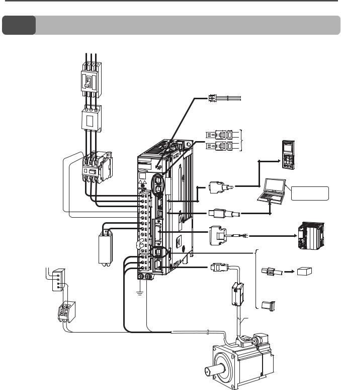
1.1 Configuration with a Rotary Servomotor
1.1  Configuration with a Rotary Servomotor
Power supply Three-phase, 200 VAC*1
R S T
Molded-case
circuit breaker
(page 12-3)
|
Analog Monitor Cable (page 10-10) |
Noise Filter |
|
(page 12-25) |
MECHATROLINK Communications Cable*1 |
|
|
(pages 10-31 and 10-32) |
|
|
|
|
SERVOPACK*1 |
|
|
|
|
To next |
|
|
|
|
MECHATROLINK-III |
||
Magnetic Contactor |
|
station*2 |
Digital Operator |
|
(page 12-6) |
|
|
(JUSP-OP05A-1-E) |
|
|
|
Digital |
(page 10-11) |
|
|
|
|
||
|
|
Operator cable |
|
|
|
|
(pages 10-12 and |
Computer |
|
|
|
10-12) |
||
|
SERVOPACK |
|
||
|
C |
|
||
|
main circuit wires |
N |
Engineering |
|
|
(page 12-10) |
6 |
||
|
|
Computer Cable |
Tool |
|
|
|
(page 13-2) |
||
|
|
(page 10-14) |
||
Control Power |
|
I/O Signal Cable |
Host controller |
|
|
|
|||
Supply Cable |
|
(pages 10-15, 10-18 and 10-21) |
||
|
External |
|
|
|
|
Regenerative |
|
|
|
External Regenerative |
Resistor |
|
|
|
Cable |
|
|
||
Resistor (page 12-32) |
Safety Function Device Cable |
|||
|
||||
200 VAC |
|
|
(page 10-30) |
|
|
|
|
||
Holding Brake |
|
|
|
|
Power Supply Unit*3, *4, *5 |
|
Safety function device |
||
|
|
|
||
|
Ground |
Brake Relay*4 |
cable |
(Wiring required for a Servomotor with a Brake)
Surge Absorbers (page 12-31)
Reactors (page 12-28)
Battery Case  (Required when an

 absolute encoder is
used.)
(page 14-4)
Servomotor  Main Circuit Cable
Refer to chapter 2 to 7 depending on the motor that you are using.
Surge Absorbers (Varistors) and Diodes for Holding Brake Power Supplies (page 14-2)
When not using a safety function, leave the Safety Jumper Connector connected to the SERVOPACK.
Encoder Cable
Refer to chapter 2 to 7 depending on the motor that you are using.
Servomotor
*1. The peripheral devices are described using a MECHATROLINK-III Communications Reference SERVOPACK for a three-phase 200-VAC power supply input as an example. The shapes of the connectors and pin layout may be different for SERVOPACKs with other power supply input specifications and for other interfaces.
Refer to the product manual for your SERVOPACK when using a SERVOPACK other than the above. *2. The connected devices depend on the interface.
For MECHATROLINK-4 communications references: Other MECHATROLINK-4 stations For MECHATROLINK-II communications references: Other MECHATROLINK-II stations For analog voltage/pulse train references: There is no CN6 connector.
*3. A Holding Brake Power Supply Unit is required to use a Servomotor with a Holding Brake. Holding Brake Power Supply Units for 24 VDC are not provided by Yaskawa. Obtain these from other manufacturers.
Never connect Holding Brake Power Supply Units with different output voltages to a SERVOPACK. Overcurrent may result in burning in the brake.
*4. If you use a Servomotor with a Holding Brake, select a brake relay according to the power supply voltage and current of the brake. Yaskawa does not recommend any particular brake relays. Select an appropriate brake relay using the selection method of the brake relay manufacturer.
*5. The power supply for the holding brake is not provided by Yaskawa. Select a power supply based on the holding brake specifications. If you use a 24-V brake, install a separate power supply for the 24-VDC power supply from other power supplies, such as the one for the I/O signals of the CN1 connector. If the power supply is shared, the I/O signals may malfunction.
1-2
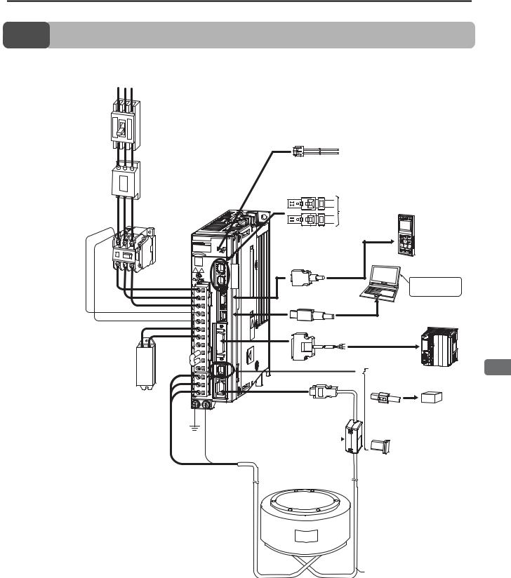
1.2 Configuration with a Direct Drive Servomotor
1.2  Configuration with a Direct Drive Servomotor
Power supply |
|
|
|
|
|
Three-phase, 200 VAC*1 |
|
|
|
|
|
R S T |
|
|
|
|
|
Molded-case |
|
|
|
|
|
circuit breaker |
|
|
|
|
|
(page 12-3) |
|
|
|
|
|
|
|
Analog Monitor Cable (page 10-10) |
|
|
|
Noise Filter |
|
|
|
|
|
(page 12-25) |
|
MECHATROLINK Communications Cable*1 |
<![if ! IE]> <![endif]>s |
||
(page 12-6) |
|
(pages 10-31 and 10-32) |
(JUSP-OP05A-1-E) |
<![if ! IE]> <![endif]>Configuration |
|
|
|
|
|
||
|
|
SERVOPACK*1 |
To next |
|
|
|
|
|
|
|
|
|
|
|
MECHATROLINK-III |
|
|
Magnetic Contactor |
|
|
station*2 |
Digital Operator |
|
|
|
cable |
|
(page 10-11) |
<![if ! IE]> <![endif]>tems |
|
|
Digital Operator |
|
|
|
|
|
(pages 10-12 and 10- |
|
<![if ! IE]> <![endif]>y |
|
|
|
|
<![if ! IE]> <![endif]>S |
||
|
|
12) |
Computer |
|
|
|
|
|
<![if ! IE]> <![endif]>and |
||
|
|
|
|
||
|
SERVOPACK |
C |
|
|
|
|
main circuit wires |
N |
|
Engineering |
<![if ! IE]> <![endif]>s |
|
(page 12-10) |
6 |
|
||
|
|
<![if ! IE]> <![endif]>Device |
|||
|
|
(page 10-14) |
|
(page 13-2) |
|
|
|
Computer Cable |
|
Tool |
|
|
|
|
|
<![if ! IE]> <![endif]>Peripheral |
|
Control Power |
External |
I/O Signal Cable |
|
Host controller |
|
|
|
|
|||
|
|
|
|
||
Supply Cable |
|
(pages 10-15, 10-18 and 10-21) |
|
||
|
Regenerative |
|
|
|
|
External Regenerative |
Resistor |
|
|
|
1 |
Cable |
|
|
|
||
Resistor |
|
Safety Function Device Cable |
|||
(page 12-32) |
|
|
|
(page 10-30) |
|
|
|
|
Safety function device |
|
|
When not using a safety function, leave the Safety Jumper Connector connected to the SERVOPACK.
Ground |
Battery Case (Required when |
|
|
|
|||
an absolute encoder is used.) |
|||
cable |
|||
(page 14-4) |
|||
|
|||
Direct Drive Servomotor
Servomotor Main  Circuit Cable
(page 8-7)
Surge Absorbers (page 12-31)
Reactors (page 12-28)
Encoder Cable
(page 8-18)
*1. The peripheral devices are described using a MECHATROLINK-III Communications Reference SERVOPACK for a three-phase 200-VAC power supply input as an example. The shapes of the connectors and pin layout may be different for SERVOPACKs with other power supply input specifications and for other interfaces.
Refer to the product manual for your SERVOPACK when using a SERVOPACK other than the above.
*2. The connected devices depend on the interface.
For MECHATROLINK-4 communications references: Other MECHATROLINK-4 stations For MECHATROLINK-II communications references: Other MECHATROLINK-II stations For analog voltage/pulse train references: There is no CN6 connector.
1-3
Loading...