


 Loading...
YASNAC PC NC
Operating Manual
YASNAC PC NC Operating Manual |
Introduction |
SAFETY INFORMATION
PRECAUTIONS
1.Read this instruction manual in its entirety before using the programming functions available in the YASNAC PC NC.
2.The following warning symbols are used to indicate precautions that the user must be aware of to safely use this equipment. Failure to follow these precautions can result in serious or possibly even fatal injury and damage to products or related equipment or systems.

 WARNING
This symbol indicates the presence of a potentially hazardous condition which, if not avoided, could result in serious personal injury or death.
This precautionary symbol appears in labels attached to YASNAC products to alert the user to conditions requiring concern for safety.
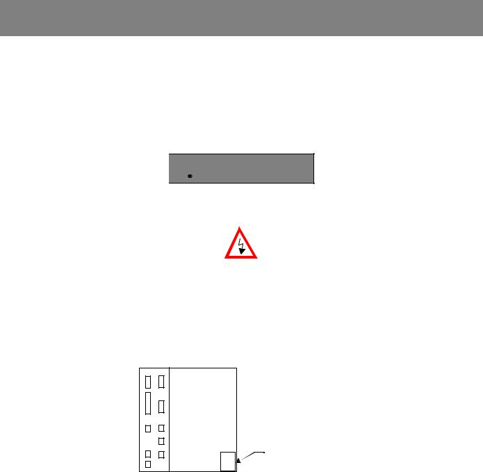
SPECIAL SAFETY NOTE: This symbol indicates that ELECTRICAL SHOCK HAZARD condition exists. DO NOT TOUCH any electrical connection terminals when the power is on, and for at least 5 minutes after switching off the power supply. Warning label is located on the CNC enclosure as shown:
PC NC Unit
xxxxxxxxx xxxxxxxxx xxxxxxxxx xxxxxxxxx xxxxxxxxx
WARNING LABEL
NOTICE
Printed _______. 2000. The information contained within this document is the proprietary property of Yaskawa Electric America, Inc., and may not be copied, reproduced or transmitted to other parties without the expressed written authorization of Yaskawa Electric America, Inc.
No patent liability is assumed with respect to the uses of the information contained herein. Moreover, because Yaskawa is constantly improving its high quality product, the information contained in this manual is subject to change without notice. Every precaution has been taken in the preparation of this document. Nevertheless, Yaskawa assumes no responsibility for damages resulting from the use of the information contained within this publication.
i
YASNAC PC NC Operating Manual |
Introduction |
USING THIS MANUAL
This manual describes the procedures for programming the YASNAC PC NC.
RELATED INFORMATION SOURCES
For additional information, refer to the following manuals
TITLE OF DOCUMENT |
CONTENTS |
|
|
|
|
|
|
|
YASNAC PC NC Operating Manual |
Basic configuration and operating procedures |
|
(YEA-SIE-C844-2.1) |
||
|
||
|
|
|
YASNAC PC NC Programming Manual |
PC NC Program creation instructions |
|
(YEA-SIE-C844-2.2) |
||
|
||
|
|
|
YASNAC PC NC PLC Programming Manual |
PLC Program creation instructions |
|
(YEA-SIE-C844-0.1) |
||
|
||
|
|
|
YASNAC PC NC I/O Signal Function |
Describes functions between PC NC and PLC |
|
(YEA-SIE-C844-2.3) |
||
|
||
|
|
|
YASNAC PC NC Connecting Manual |
Instructions for connecting PC NC with machines, |
|
(YEA-SIE-C844-0.2) |
machine interface and peripheral equipment |
|
|
|
|
|
Describes man-machine-interface (MMI) programming, |
|
|
specifications and definitions. |
|
|
|
|
MEMOCON GL120,G130 120 Series |
|
|
I/O Module User’s Manual |
Describes I/O power supply specifications |
|
(Document No. SIEZ-C825-20.22) |
|
|
|
|
|
MEMOCON GL120,G130 Hardware User’s Manual |
Describes the AC input power supply specifications for I/O. |
|
(Document No. SIEZ-C825-20.1) |
||
|
||
|
|
|
YASNAC PC NC Maintenance Manual |
Describes service and maintenance procedures. |
|
(YEA-SIE-C844-2.9) |
||
|
||
|
|
ii

YASNAC PC NC Operating Manual |
Introduction |
INFORMATION INDICATORS
The following symbols are used in this programming manual to emphasize particular information to the user:
Indicates important information to be remembered, i.e., precautionary alarm displays to prevent damaging devices.
Indicates supplementary material.
Indicates definitions of terminology that has not been explained before.
NOTES REGARDING SAFE OPERATION
It is important that the user should read this manual before installing, operating, performing any
maintenance or inspecting the YASNAC PC NC. Also, the functions and performance of a NC machine tool are not determined by the CNC unit itself, therefore thoroughly read and familiarize yourself with the machine builder’s documentation concerning the safe and most efficient ways to use the machine tool.
iii
YASNAC PC NC Operating Manual |
Introduction |
TABLE OF CONTENTS
Chapter 1
1.1 Outline of the YASNAC System . . . . . . . . . . . . . . . . . . . . . . . . . . . . . . . . . . . . 1-2
|
1.1.1 |
System Configuration . . . . . . . . . . . . . . . . . . . . . . . . . . . . . . . . . . . . . . |
1-2 |
|
1.1.2 |
Environmental Requirements . . . . . . . . . . . . . . . . . . . . . . . . . . . . . . . . . |
1-3 |
|
1.1.3 |
Machine Operation Panel . . . . . . . . . . . . . . . . . . . . . . . . . . . . . . . . . . . . |
1-4 |
|
1.1.4 |
General Specifications . . . . . . . . . . . . . . . . . . . . . . . . . . . . . . . . . . . . . . |
1-5 |
1.2 |
Protective Functions . . . . . . . . . . . . . . . . . . . . . . . . . . . . . . . . . . . . . . . . . . . . . . |
1-9 |
|
1.2.1 Emergency Stop . . . . . . . . . . . . . . . . . . . . . . . . . . . . . . . . . . . . . . . . . . . 1-9
1.2.2 Overtravel . . . . . . . . . . . . . . . . . . . . . . . . . . . . . . . . . . . . . . . . . . . . . . . . 1-9
1.2.3 Stored Stroke Limit . . . . . . . . . . . . . . . . . . . . . . . . . . . . . . . . . . . . . . . 1-10
1.2.4 Interlock Inputs . . . . . . . . . . . . . . . . . . . . . . . . . . . . . . . . . . . . . . . . . . 1-11
Chapter 2
2.1 |
General Operation Flow . . . . . . . . . . . . . . . . . . . . . . . . . . . . . . . . . . . . . . . . . . |
. 2-2 |
|
2.2 |
Inspection Before Turning the Power ON . . . . . . . . . . . . . . . . . . . . . . . . . . . . . |
2-3 |
|
|
2.2.1 Inspection of the NC Unit . . . . . . . . . . . . . . . . . . . . . . . . . . . . . . . . . . . |
2-4 |
|
|
2.2.2 Preparation before Turning the Power ON . . . . . . . . . . . . . . . . . . . . . . . |
2- 5 |
|
2.3 |
Turning the Power ON and Inspecting After Power ON . . . . . . . . . . . . . . . . . . |
2-6 |
|
|
2.3.1 Procedure for Turning the Power ON . . . . . . . . . . . . . . . . . . . . . . . . . . |
2-6 |
|
|
2.3.2 Checking the Motors for Abnormalities . . . . . . . . . . . . . . . . . . . . . . . . |
2-7 |
|
|
2.3.3 Procedure for Turning Power OFF . . . . . . . . . . . . . . . . . . . . . . . . . . . . |
2-7 |
|
|
2.3.4 Inspection of the Battery . . . . . . . . . . . . . . . . . . . . . . . . . . . . . . . . . . . . |
2-8 |
|
2.4 |
Manual Operation (1) . . . . . . . . . . . . . . . . . . . . . . . . . . . . . . . . . . . . . . . . . . . . |
2-11 |
|
|
2.4.1 Manual Rapid Traverse (RAPID) . . . . . . . . . . . . . . . . . . . . . . . . . . . . |
2-11 |
|
|
2.4.2 |
Jog Feed (JOG) . . . . . . . . . . . . . . . . . . . . . . . . . . . . . . . . . . . . . . . . . . |
2-11 |
|
2.4.3 |
Step Feed (STEP) . . . . . . . . . . . . . . . . . . . . . . . . . . . . . . . . . . . . . . . . . |
2-12 |
|
2.4.4 |
Handle Feed (HANDLE)* . . . . . . . . . . . . . . . . . . . . . . . . . . . . . . . . . . |
2-12 |
2.5 |
Manual Operation (2) . . . . . . . . . . . . . . . . . . . . . . . . . . . . . . . . . . . . . . . . . . . . |
2-13 |
|
iv
YASNAC PC NC Operating Manual |
Introduction |
2.5.1 Simultaneous 2 or 3-axis Handle Feed * . . . . . . . . . . . . . . . . . . . . . . . 2-13 2.5.2 Manual Reference Point Return . . . . . . . . . . . . . . . . . . . . . . . . . . . . . . 2-14
2.5.3Manual Reference Point Return to the Second Reference Point* . . . . 2-16
2.5.4 1-line MDI . . . . . . . . . . . . . . . . . . . . . . . . . . . . . . . . . . . . . . . . . . . . . . 2-17
2.6 Automatic Operation (1) . . . . . . . . . . . . . . . . . . . . . . . . . . . . . . . . . . . . . . . . . 2-18
2.6.1 Preparation of Automatic Operation . . . . . . . . . . . . . . . . . . . . . . . . . . 2-18
2.6.2 MDI Operation . . . . . . . . . . . . . . . . . . . . . . . . . . . . . . . . . . . . . . . . . . . 2-21
2.6.3 Feed Hold . . . . . . . . . . . . . . . . . . . . . . . . . . . . . . . . . . . . . . . . . . . . . . . 2-21
2.6.4 Override . . . . . . . . . . . . . . . . . . . . . . . . . . . . . . . . . . . . . . . . . . . . . . . . 2-21
2.7 Automatic Operation (2) . . . . . . . . . . . . . . . . . . . . . . . . . . . . . . . . . . . . . . . . . 2-23
2.7.1 Optional Stop . . . . . . . . . . . . . . . . . . . . . . . . . . . . . . . . . . . . . . . . . . . . 2-23 2.7.2 Optional Block Skip . . . . . . . . . . . . . . . . . . . . . . . . . . . . . . . . . . . . . . . 2-23 2.7.3 Dry Run . . . . . . . . . . . . . . . . . . . . . . . . . . . . . . . . . . . . . . . . . . . . . . . . 2-24 2.7.4 Display Lock and Machine Lock . . . . . . . . . . . . . . . . . . . . . . . . . . . . . 2-24 2.7.5 Auxiliary Function Lock . . . . . . . . . . . . . . . . . . . . . . . . . . . . . . . . . . . 2-25 2.7.6 Z-axis Command Neglect . . . . . . . . . . . . . . . . . . . . . . . . . . . . . . . . . . 2-25 2.7.7 4th-axis Command Neglect . . . . . . . . . . . . . . . . . . . . . . . . . . . . . . . . . 2-25 2.7.8 5th-axis Command Neglect . . . . . . . . . . . . . . . . . . . . . . . . . . . . . . . . . 2-26
2.8 Operation Intervention During Automatic Operation . . . . . . . . . . . . . . . . . . . 2-27
2.8.1 MDI Operation Intervention during Automatic Operation . . . . . . . . . 2-28 2.8.2 Automatic Handle Mode Offset * . . . . . . . . . . . . . . . . . . . . . . . . . . . . 2-28 2.8.3 Manual Absolute . . . . . . . . . . . . . . . . . . . . . . . . . . . . . . . . . . . . . . . . . 2-30
Chapter 3
3.1 USER INTERFACE OVERVIEW . . . . . . . . . . . . . . . . . . . . . . . . . . . . . . . . . . |
3-7 |
|
3.1.1 |
Status Bar . . . . . . . . . . . . . . . . . . . . . . . . . . . . . . . . . . . . . . . . . . . . . . . . |
3-7 |
3.1.2 |
Battery Indicator . . . . . . . . . . . . . . . . . . . . . . . . . . . . . . . . . . . . . . . . . . |
3-7 |
3.1.3 |
NC Execution Status . . . . . . . . . . . . . . . . . . . . . . . . . . . . . . . . . . . . . . . |
3-8 |
3.1.4 |
Motion Status . . . . . . . . . . . . . . . . . . . . . . . . . . . . . . . . . . . . . . . . . . . . . |
3-8 |
3.1.5 |
Alarm Message . . . . . . . . . . . . . . . . . . . . . . . . . . . . . . . . . . . . . . . . . . . |
3-9 |
3.1.6 |
Warning Message . . . . . . . . . . . . . . . . . . . . . . . . . . . . . . . . . . . . . . . . . . |
3-9 |
v
YASNAC PC NC Operating Manual |
Introduction |
3.1.7 Time/Date . . . . . . . . . . . . . . . . . . . . . . . . . . . . . . . . . . . . . . . . . . . . . . . 3-11
3.1.8 Mode / MDI / Toolbar . . . . . . . . . . . . . . . . . . . . . . . . . . . . . . . . . . . . . 3-11
3.1.9 Mode Indicator . . . . . . . . . . . . . . . . . . . . . . . . . . . . . . . . . . . . . . . . . . . 3-12
3.1.10 Menu Bar . . . . . . . . . . . . . . . . . . . . . . . . . . . . . . . . . . . . . . . . . . . . . . . 3-18
3.2 RECURRING COMPONENTS . . . . . . . . . . . . . . . . . . . . . . . . . . . . . . . . . . . 3-19
|
3.2.1 |
Position Display . . . . . . . . . . . . . . . . . . . . . . . . . . . . . . . . . . . . . . . . . . |
3-19 |
|
3.2.2 |
Program Display . . . . . . . . . . . . . . . . . . . . . . . . . . . . . . . . . . . . . . . . . |
3-20 |
|
3.2.3 |
Nest Level Display . . . . . . . . . . . . . . . . . . . . . . . . . . . . . . . . . . . . . . . . |
3-21 |
|
3.2.4 |
Shortcuts . . . . . . . . . . . . . . . . . . . . . . . . . . . . . . . . . . . . . . . . . . . . . . . . |
3-22 |
|
3.2.5 |
Number Field . . . . . . . . . . . . . . . . . . . . . . . . . . . . . . . . . . . . . . . . . . . . |
3-22 |
|
3.2.6 |
File Browser . . . . . . . . . . . . . . . . . . . . . . . . . . . . . . . . . . . . . . . . . . . . . |
3-23 |
3.3 |
RUN MENU . . . . . . . . . . . . . . . . . . . . . . . . . . . . . . . . . . . . . . . . . . . . . . . . . . |
3-25 |
|
|
3.3.1 |
Production Screen . . . . . . . . . . . . . . . . . . . . . . . . . . . . . . . . . . . . . . . . |
3-25 |
|
3.3.2 |
Proveout Screen . . . . . . . . . . . . . . . . . . . . . . . . . . . . . . . . . . . . . . . . . . |
3-27 |
|
3.3.3 |
NC Switch Screen . . . . . . . . . . . . . . . . . . . . . . . . . . . . . . . . . . . . . . . . |
3-33 |
|
3.3.4 |
Timers Screen . . . . . . . . . . . . . . . . . . . . . . . . . . . . . . . . . . . . . . . . . . . |
3-34 |
|
3.3.5 Tool Path Drawing Screen . . . . . . . . . . . . . . . . . . . . . . . . . . . . . . . . . |
3-36 |
|
3.4 |
PROGRAM MENU . . . . . . . . . . . . . . . . . . . . . . . . . . . . . . . . . . . . . . . . . . . . . |
3-40 |
|
|
3.4.1 |
File Screen . . . . . . . . . . . . . . . . . . . . . . . . . . . . . . . . . . . . . . . . . . . . . . |
3-40 |
|
3.4.2 |
Editor Screen . . . . . . . . . . . . . . . . . . . . . . . . . . . . . . . . . . . . . . . . . . . . |
3-46 |
|
3.4.3 |
List Screen . . . . . . . . . . . . . . . . . . . . . . . . . . . . . . . . . . . . . . . . . . . . . . |
3-53 |
|
3.4.4 |
Macro Variables . . . . . . . . . . . . . . . . . . . . . . . . . . . . . . . . . . . . . . . . . . |
3-55 |
3.5 |
TOOL MENU . . . . . . . . . . . . . . . . . . . . . . . . . . . . . . . . . . . . . . . . . . . . . . . . . |
3-57 |
|
|
3.5.1 |
Offsets Screen . . . . . . . . . . . . . . . . . . . . . . . . . . . . . . . . . . . . . . . . . . . |
3-57 |
|
3.5.2 |
Magazine Screen . . . . . . . . . . . . . . . . . . . . . . . . . . . . . . . . . . . . . . . . . |
3-59 |
3.6 |
SETUP MENU . . . . . . . . . . . . . . . . . . . . . . . . . . . . . . . . . . . . . . . . . . . . . . . . . |
3-61 |
|
|
3.6.1 |
Workshift Screen . . . . . . . . . . . . . . . . . . . . . . . . . . . . . . . . . . . . . . . . . |
.3-61 |
|
3.6.2 Four (4) Positions Screen . . . . . . . . . . . . . . . . . . . . . . . . . . . . . . . . . . . |
3-63 |
|
|
3.6.3 One (1) Position Screen . . . . . . . . . . . . . . . . . . . . . . . . . . . . . . . . . . . . |
3-64 |
|
3.7 |
UTILITIES MENU . . . . . . . . . . . . . . . . . . . . . . . . . . . . . . . . . . . . . . . . . . . . . |
3-65 |
|
3.7.1 Login Screen . . . . . . . . . . . . . . . . . . . . . . . . . . . . . . . . . . . . . . . . . . . . 3-65
vi
YASNAC PC NC Operating Manual |
|
Introduction |
|
|
3.7.2 |
PC Settings Screen . . . . . . . . . . . . . . . . . . . . . . . . . . . . . . . . . . . . |
. . . . 3-67 |
|
3.7.3 |
Maintenance Screen . . . . . . . . . . . . . . . . . . . . . . . . . . . . . . . . . . |
. . . . 3-69 |
|
3.7.4 |
Configuration Screen . . . . . . . . . . . . . . . . . . . . . . . . . . . . . . . . . . |
. . . . 3-70 |
|
3.7.5 |
Backup and Restore Screen . . . . . . . . . . . . . . . . . . . . . . . . . . . . . |
. . . . 3-72 |
|
3.7.6 |
CPU Monitor Screen . . . . . . . . . . . . . . . . . . . . . . . . . . . . . . . . . . |
. . . . 3-74 |
|
3.7.7 |
Setting Parameters Screen . . . . . . . . . . . . . . . . . . . . . . . . . . . . . . |
. . . . 3-75 |
|
3.7.8 |
NC Parameters Screen . . . . . . . . . . . . . . . . . . . . . . . . . . . . . . . . |
. . . . 3-78 |
|
3.7.9 |
Machine Setup Screen . . . . . . . . . . . . . . . . . . . . . . . . . . . . . . . . . |
. . . . 3-79 |
|
3.7.10 |
Pitch Error Screen . . . . . . . . . . . . . . . . . . . . . . . . . . . . . . . . . . . . |
. . . . 3-80 |
|
3.7.11 |
Solid Tap Screen . . . . . . . . . . . . . . . . . . . . . . . . . . . . . . . . . . . . . |
. . . . 3-82 |
|
3.7.12 |
Torque Ripple Screen . . . . . . . . . . . . . . . . . . . . . . . . . . . . . . . . . |
. . . . 3-83 |
|
3.7.13 |
Parameter Search Screen . . . . . . . . . . . . . . . . . . . . . . . . . . . . . . . |
. . . . 3-84 |
|
3.7.14 |
High Speed Cutting Screen . . . . . . . . . . . . . . . . . . . . . . . . . . . . . |
. . . . 3-86 |
|
3.7.15 |
User Install Screen . . . . . . . . . . . . . . . . . . . . . . . . . . . . . . . . . . . |
. . . . 3-87 |
|
3.7.16 |
MTB Install Screen . . . . . . . . . . . . . . . . . . . . . . . . . . . . . . . . . . . |
. . . . 3-90 |
|
3.7.17 |
PLC Parameters Screen . . . . . . . . . . . . . . . . . . . . . . . . . . . . . . . . |
. . . . 3-91 |
|
3.7.18 |
PLC Diagnosis Screen . . . . . . . . . . . . . . . . . . . . . . . . . . . . . . . . . |
. . . . 3-92 |
|
3.7.19 |
Ladder Monitor Screen . . . . . . . . . . . . . . . . . . . . . . . . . . . . . . . . |
. . . . 3-97 |
|
3.7.20 |
Switch Label Screen . . . . . . . . . . . . . . . . . . . . . . . . . . . . . . . . . . . |
. . . . 3-97 |
3.8 |
ALARM MENU . . . . . . . . . . . . . . . . . . . . . . . . . . . . . . . . . . . . . . . . . . . |
. . . 3-100 |
|
|
3.8.1 |
NC Alarm Screen . . . . . . . . . . . . . . . . . . . . . . . . . . . . . . . . . . . . |
. . . 3-100 |
|
3.8.2 |
PLC Alarm Screen . . . . . . . . . . . . . . . . . . . . . . . . . . . . . . . . . . . |
. . . 3-101 |
|
3.8.3 |
Alarm History Screen . . . . . . . . . . . . . . . . . . . . . . . . . . . . . . . . . |
. . . 3-102 |
3.9 |
HELP MENU . . . . . . . . . . . . . . . . . . . . . . . . . . . . . . . . . . . . . . . . . . . . . . |
. . . 3-104 |
|
|
3.9.1 |
MMI Map Screen . . . . . . . . . . . . . . . . . . . . . . . . . . . . . . . . . . . . |
. . . 3-104 |
|
3.9.2 |
Manual Screen . . . . . . . . . . . . . . . . . . . . . . . . . . . . . . . . . . . . . . . |
. . . 3-105 |
|
3.9.3 |
About Screen . . . . . . . . . . . . . . . . . . . . . . . . . . . . . . . . . . . . . . . . |
. . . 3-106 |
3.10 |
OFF LINE MODE . . . . . . . . . . . . . . . . . . . . . . . . . . . . . . . . . . . . . . . . . . |
. . . 3-107 |
|
|
3.10.1 The Offline Mode Interface . . . . . . . . . . . . . . . . . . . . . . . . . . . . |
. . . 3-107 |
|
vii
YASNAC PC NC Operating Manual |
Introduction |
Chapter 4
4.1 MAINTENANCE DATA . . . . . . . . . . . . . . . . . . . . . . . . . . . . . . . . . . . . . . . . . 4-2
4.1.1 Checking the Status of Problems . . . . . . . . . . . . . . . . . . . . . . . . . . . . . . 4-2 4.1.2 Checking the NC Information . . . . . . . . . . . . . . . . . . . . . . . . . . . . . . . . 4-3 4.1.3 Display of Alarm Information. . . . . . . . . . . . . . . . . . . . . . . . . . . . . . . . . 4-3 4.1.4 Cause of Alarm and Corrective Action . . . . . . . . . . . . . . . . . . . . . . . . . 4-4 4.1.5 Troubleshooting (1) . . . . . . . . . . . . . . . . . . . . . . . . . . . . . . . . . . . . . . . . 4-5 4.1.6 Troubleshooting (2) . . . . . . . . . . . . . . . . . . . . . . . . . . . . . . . . . . . . . . . 4-11 4.1.7 Alarms Not Indicated by Alarm Numbers . . . . . . . . . . . . . . . . . . . . . . 4-15 4.1.8 PC NC Alarms Not Indicated By Alarm Numbers . . . . . . . . . . . . . . . 4-26 4.1.9 Touch Screen Maintenance . . . . . . . . . . . . . . . . . . . . . . . . . . . . . . . . . 4-27 4.1.10 Mode of Operation of PC NC . . . . . . . . . . . . . . . . . . . . . . . . . . . . . . . 4-27 4.1.11 Self - Diagnosis Function Specification . . . . . . . . . . . . . . . . . . . . . . . . 4-28 4.1.12 Hard Drive Mounting Replacement . . . . . . . . . . . . . . . . . . . . . . . . . . . 4-29
viii

YASNAC PC NC Operating Manual |
Chapter 1: Outline of the YASNAC System |
1
Outline of the YASNAC System
Chapter 1 describes the outline of the YASNAC system and the operating features and functions that should be thoroughly understood for the safe and efficient operation of the system.
1.1 Outline of the YASNAC System . . . . . . . . . . . . . . . . . . . . . . . . . . . . . . . . . . . . 1-2
|
1.1.1 |
System Configuration . . . . . . . . . . . . . . . . . . . . . . . . . . . . . . . . . . . . . . |
.1-2 |
|
1.1.2 |
Environmental Requirements . . . . . . . . . . . . . . . . . . . . . . . . . . . . . . . . . |
1-3 |
|
1.1.3 |
Machine Operation Panel . . . . . . . . . . . . . . . . . . . . . . . . . . . . . . . . . . . . . |
1-4 |
|
1.1.4 |
General Specifications . . . . . . . . . . . . . . . . . . . . . . . . . . . . . . . . . . . . . . . |
1-5 |
1.2 |
Protective Functions . . . . . . . . . . . . . . . . . . . . . . . . . . . . . . . . . . . . . . . . . . . . . |
1-9 |
|
1.2.1 Emergency Stop . . . . . . . . . . . . . . . . . . . . . . . . . . . . . . . . . . . . . . . . . . . .1-9
1.2.2 Overtravel . . . . . . . . . . . . . . . . . . . . . . . . . . . . . . . . . . . . . . . . . . . . . . . . .1-9
1.2.3 Stored Stroke Limit . . . . . . . . . . . . . . . . . . . . . . . . . . . . . . . . . . . . . . . .1-10
1.2.4 Interlock Inputs . . . . . . . . . . . . . . . . . . . . . . . . . . . . . . . . . . . . . . . . . . .1-11
1 - 1
YASNAC PC NC Operating Manual |
Chapter 1: Outline of the YASNAC System |
1.1Outline of the YASNAC System
1.1.1System Configuration
PC NC The configuration of the YASNAC PC NC system and the list of components are described below.
|
|
|
|
Unit |
|
|
|
|
|
|
|
|
|
|
Remote |
|
|
|
|
YASNAC PC NC |
||||
Machine |
|
|
|
Unit |
Pendant |
|
|
|
|
|
||||
|
|
|
|
|
Fig. 1.1.1.1 Standard Configuration of PC NC System
Table 1.1.1.1 List of YASNAC PC NC System Components
COMPONENT NAME |
MODEL NAME |
|
|
|
|
CPU rack |
JZNC-JPCRKM- - - |
|
|
NC Operation Panel |
JZNC-JPCOP- - |
|
|
SERVOPACK |
SGDC- |
|
|
Spindle drive |
CIMR-M5 |
|
|
Servomotor |
SGM - |
|
|
Spindle motor |
UAASKA- |
|
|
Remote Pendant |
TBA |
|
|
1 - 2

YASNAC PC NC Operating Manual |
Chapter 1: Outline of the YASNAC System |
1.1.2Environmental Requirements
Requirements for the installation of an PC NC unit are indicated below. Install the PC NC unit in a location where only these requirements are satisfied to avoid possible malfunctioning.
CAUTION!
Avoid using it in an environment where it may be subject to high temperatures, high humidity, dust, corrosive gases, vibration or physical impacts that may cause fire, electric shock or malfunction.
•Use the product in an environment meeting the following conditions:
•Free from gases or vapors that create a potentially explosive atmosphere.
•Free from oil, organic solvents, etc.
•Relative humidity in the range 10 to 90% RH, with no condensation.
•Ambient temperature in the 0°C to 55°C with no freezing.
(Installation site must not be exposed to direct sunlight, must be distanced from heat generating devices, and must be indoors.)
•Vibration not exceeding 4.9 m/s2.
•Do not store the product in locations subject to rain, water droplets, harmful gases or liquids.
Failure to observe this caution may result in product failure.
•Select a storage area indoors that is clean and meets the following temperature and humidity requirements.
Ambient temperature: –15° C to 65° C (–5° F to 149° F)
Relative humidity: 10% to 90%
Failure to observe this caution may result in product failure.
(1) Ambient Temperature |
|
For operation: |
0°C to 55°C |
For storage and transportation: |
–15° C to 65° C |
Install the PC NC unit in a location not subject to direct sunlight, distant from heat sources, and indoors.
(2)Humidity
Relative humidity must be in the range of 10 to 90%RH (non-condensing).
(3)Vibration
During operation: Max. 4.9 m/s2
1 - 3
YASNAC PC NC Operating Manual |
Chapter 1: Outline of the YASNAC System |
(4)Atmosphere
Avoid the following locations:
•Dusty places
•Places where concentration of coolant and/or organic solvent mist is extremely high.
(5)Power Source
Input voltage: |
AC (single-phase) 180V ~ 264V |
Frequency: |
50/60 Hz –2 to +2 Hz |
1.1.3Machine Operation Panel
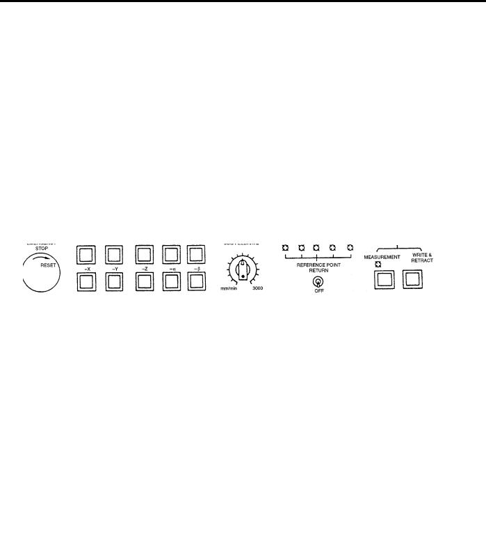
An example of the machine operation panel is indicated below. Arrangement and names of switches and indicator lamps vary according to the machine model. For details, refer to the machine tool manual.
Fig. 1.1.3.1 Example of Machine Operation Panel
1 - 4

YASNAC PC NC Operating Manual |
Chapter 1: Outline of the YASNAC System |
1.1.4General Specifications
(1)Standard Specifications
CATEGOR |
ITEM AND FUNCTION |
OPERATION |
PROGRAMMING |
SECTION |
||
MANUAL |
MANUAL |
NO. |
||||
|
|
|
||||
|
|
|
|
|
|
|
|
|
|
|
|
|
|
Controlled |
Controlled axes |
|
|
|
||
axes |
|
|
|
|
|
|
|
Number of simultaneously controlled axes |
|
|
|
||
|
|
|
|
|
||
|
|
|
|
|
||
Input |
Least input increment |
|
|
|
||
command |
|
|
|
|
|
|
|
Least output increment |
|
|
|
||
|
|
|
|
|
||
|
|
|
|
|
|
|
|
|
Maximum programmable value |
|
|
|
|
|
|
|
|
|
|
|
|
|
Absolute/incremental programming |
|
|
|
|
|
|
|
|
|
|
|
|
|
Decimal point input |
|
|
|
|
|
|
|
|
|
|
|
|
|
Input unit 10 times |
|
|
|
|
|
|
|
|
|
|
|
|
|
Tape code |
|
|
|
|
|
|
|
|
|
|
|
|
|
NC tape |
|
|
|
|
|
|
|
|
|
|
|
|
|
Input format |
|
|
|
|
|
|
|
|
|
|
|
|
|
Buffer register |
|
|
|
|
|
|
|
|
|
||
Interpolation |
Positioning |
|
|
|
||
|
|
|
|
|
|
|
|
|
Linear interpolation |
|
|
|
|
|
|
|
|
|
|
|
|
|
Circular interpolation |
|
|
|
|
|
|
|
|
|
||
Feed |
Rapid traverse |
|
|
|
||
|
|
|
|
|
|
|
|
|
Cutting feed |
|
|
|
|
|
|
|
|
|
|
|
|
|
Dwell |
|
|
|
|
|
|
|
|
|
|
|
|
|
Incremental feed |
|
|
|
|
|
|
|
|
|
|
|
|
|
Automatic acceleration and deceleration |
|
|
|
|
|
|
|
|
|
||
Storage and |
Program storage capacity |
|
|
|
||
editing of |
|
|
|
|
|
|
|
Number of programs |
|
|
|
||
program |
|
|
|
|
||
|
|
|
|
|
||
|
Program editing |
|
|
|
||
|
|
|
|
|
||
|
|
|
|
|
|
|
|
|
Program number search |
|
|
|
|
|
|
|
|
|
|
|
|
|
Sequence number search |
|
|
|
|
|
|
|
|
|
|
|
|
|
Address search |
|
|
|
|
|
|
|
|
|
|
|
|
|
MDI editing |
|
|
|
|
|
|
|
|
|
||
Operation |
Operation panel |
|
|
|
||
and |
|
|
|
|
|
|
|
MDI function |
|
|
|
||
display |
|
|
|
|
||
|
|
|
|
|
||
|
l-line MDI |
|
|
|
||
|
|
|
|
|
||
|
|
|
|
|
|
|
|
|
Operation and display |
|
|
|
|
|
|
|
|
|
|
|
|
|
Calendar display |
|
|
|
|
|
|
|
|
|
|
|
|
|
Pop-up menu |
|
|
|
|
|
|
|
|
|
|
|
|
|
Buzzer function |
|
|
|
|
|
|
|
|
|
||
Input/Output |
Input/Output interface |
|
|
|
||
function |
|
|
|
|||
|
|
|
|
|||
|
|
|
|
|
|
|
1 - 5
YASNAC PC NC Operating Manual |
|
Chapter 1: Outline of the YASNAC System |
||||||
|
|
|
|
|
|
|
|
|
|
|
|
|
|
|
|
|
|
|
CATEGOR |
ITEM AND FUNCTION |
OPERATION |
|
PROGRAMMING |
SECTION |
|
|
|
MANUAL |
|
MANUAL |
NO. |
|
|||
|
|
|
|
|
|
|||
|
|
|
|
|
|
|
|
|
|
|
|
|
|
|
|
|
|
|
Tool offset |
Tool function |
|
|
|
|
|
|
|
|
|
|
|
|
|
|
|
|
|
|
Miscellaneous function |
|
|
|
|
|
|
|
|
|
|
|
|
|
|
|
|
|
Tool length offset |
|
|
|
|
|
|
|
|
|
|
|
|
|
|
|
|
|
Tool position offset |
|
|
|
|
|
|
|
|
|
|
|
|
|
|
|
|
|
Number of tool offset data sets |
|
|
|
|
|
|
|
|
|
|
|
|
|
|
|
Coordinate |
Manual return to reference point |
|
|
|
|
|
|
|
system |
|
|
|
|
|
|
|
|
|
Automatic return to reference point |
|
|
|
|
|
|
|
|
|
|
|
|
|
|
|
|
|
|
|
|
|
|
|
|
|
|
|
Automatic return to second reference point |
|
|
|
|
|
|
|
|
|
|
|
|
|
|
|
|
|
Reference point return check |
|
|
|
|
|
|
|
|
|
|
|
|
|
|
|
|
|
Return from reference point |
|
|
|
|
|
|
|
|
|
|
|
|
|
|
|
|
|
Base coordinate system setting |
|
|
|
|
|
|
|
|
|
|
|
|
|
|
|
Operation |
Label skip |
|
|
|
|
|
|
|
support |
|
|
|
|
|
|
|
|
|
Single block |
|
|
|
|
|
|
|
function |
|
|
|
|
|
|
|
|
|
|
|
|
|
|
|
|
|
|
Optional stop |
|
|
|
|
|
|
|
|
|
|
|
|
|
|
|
|
|
|
|
|
|
|
|
|
|
|
|
Optional block skip |
|
|
|
|
|
|
|
|
|
|
|
|
|
|
|
|
|
Dry run |
|
|
|
|
|
|
|
|
|
|
|
|
|
|
|
|
|
Machine lock |
|
|
|
|
|
|
|
|
|
|
|
|
|
|
|
|
|
Miscellaneous function lock |
|
|
|
|
|
|
|
|
|
|
|
|
|
|
|
|
|
Display lock |
|
|
|
|
|
|
|
|
|
|
|
|
|
|
|
|
|
Manual absolute |
|
|
|
|
|
|
|
|
|
|
|
|
|
|
|
|
|
Numerical value set-up |
|
|
|
|
|
|
|
|
|
|
|
|
|
|
|
|
|
Break-point function |
|
|
|
|
|
|
|
|
|
|
|
|
|
|
|
|
|
Operation mode |
|
|
|
|
|
|
|
|
|
|
|
|
|
|
|
|
|
Feed hold |
|
|
|
|
|
|
|
|
|
|
|
|
|
|
|
Programming |
Circular interpolation by R command |
|
|
|
|
|
|
|
support |
|
|
|
|
|
|
|
|
|
Repetitive circle interpolation |
|
|
|
|
|
|
|
function |
|
|
|
|
|
|
|
|
|
|
|
|
|
|
|
|
|
|
Subprogram |
|
|
|
|
|
|
|
|
|
|
|
|
|
|
|
|
|
|
|
|
|
|
|
|
|
|
|
Exact stop check |
|
|
|
|
|
|
|
|
|
|
|
|
|
|
|
|
|
Exact stop check mode |
|
|
|
|
|
|
|
|
|
|
|
|
|
|
|
Safety and |
Emergency stop input |
|
|
|
|
|
|
|
maintenance |
|
|
|
|
|
|
|
|
|
Overtravel |
|
|
|
|
|
|
|
|
|
|
|
|
|
|
|
|
|
|
|
|
|
|
|
|
|
|
|
Axis interlock |
|
|
|
|
|
|
|
|
|
|
|
|
|
|
|
|
|
Stored stroke limit |
|
|
|
|
|
|
|
|
|
|
|
|
|
|
|
|
|
Self-diagnostics (always displayed) |
|
|
|
|
|
|
|
|
|
|
|
|
|
|
|
Environment |
Power supply |
|
|
|
|
|
|
|
requirements |
|
|
|
|
|
|
|
|
|
Ambient temperature |
|
|
|
|
|
|
|
|
|
|
|
|
|
|
|
|
|
|
|
|
|
|
|
|
|
|
|
Humidity |
|
|
|
|
|
|
|
|
|
|
|
|
|
|
1 - 6
YASNAC PC NC Operating Manual |
|
Chapter 1: Outline of the YASNAC System |
||||||
|
|
|
|
|
|
|
|
|
|
(2) Option Specifications |
|
|
|
|
|
||
|
|
|
|
|
|
|
|
|
|
CATEGOR |
ITEM AND FUNCTION |
OPERATION |
|
PROGRAMMING |
SECTION |
|
|
|
MANUAL |
|
MANUAL |
NO. |
|
|||
|
|
|
|
|
|
|||
|
|
|
|
|
|
|
|
|
|
|
|
|
|
|
|
|
|
|
Controlled |
Number of controlled axes |
|
|
|
|
|
|
|
axes |
|
|
|
|
|
|
|
|
|
Rotary axis control |
|
|
|
|
|
|
|
|
|
|
|
|
|
|
|
|
|
|
|
|
|
|
|
|
|
Input |
Least input/output increment of rotary axis |
|
|
|
|
|
|
|
command |
|
|
|
|
|
|
|
|
|
Inch/metric switching |
|
|
|
|
|
|
|
|
|
|
|
|
|
|
|
|
|
|
|
|
|
|
|
|
|
|
|
Multi-active registers |
|
|
|
|
|
|
|
|
|
|
|
|
|
|
|
Interpolation |
Helical interpolation |
|
|
|
|
|
|
|
|
|
|
|
|
|
|
|
|
Feed |
Synchronized feed (solid tap) |
|
|
|
|
|
|
|
|
|
|
|
|
|
|
|
|
|
|
High-speed mode operation |
|
|
|
|
|
|
|
|
|
|
|
|
|
|
|
|
|
F1-digit |
|
|
|
|
|
|
|
|
|
|
|
|
|
|
|
|
|
Simultaneous1-axis handle feed |
|
|
|
|
|
|
|
|
|
|
|
|
|
|
|
|
|
Simultaneous 2-axis handle feed |
|
|
|
|
|
|
|
|
|
|
|
|
|
|
|
|
|
Simultaneous 3-axis handle feed |
|
|
|
|
|
|
|
|
|
|
|
|
|
|
|
Storage and |
Addition of program storage capacity |
|
|
|
|
|
|
|
editing of |
|
|
|
|
|
|
|
|
|
Addition of number of programs |
|
|
|
|
|
|
|
program |
|
|
|
|
|
|
|
|
|
|
|
|
|
|
|
|
|
|
Playback |
|
|
|
|
|
|
|
|
|
|
|
|
|
|
|
|
|
|
|
|
|
|
|
|
|
Operation |
Internal toggle switch |
|
|
|
|
|
|
|
and display |
|
|
|
|
|
|
|
|
|
NC program drawing |
|
|
|
|
|
|
|
|
|
|
|
|
|
|
|
|
|
|
|
|
|
|
|
|
|
|
|
Comment display function |
|
|
|
|
|
|
|
|
|
|
|
|
|
|
|
Input/output |
Tape reader without take-up reels |
|
|
|
|
|
|
|
function and |
|
|
|
|
|
|
|
|
|
Tape reader with take-up reels |
|
|
|
|
|
|
|
device |
|
|
|
|
|
|
|
|
|
|
|
|
|
|
|
|
|
|
RS-232C interface |
|
|
|
|
|
|
|
|
|
|
|
|
|
|
|
|
|
|
|
|
|
|
|
|
|
Spindle, tool |
T4-digit command |
|
|
|
|
|
|
|
and miscella- |
|
|
|
|
|
|
|
|
neous func- |
|
|
|
|
|
|
|
|
|
Second miscellaneous function |
|
|
|
|
|
|
|
tions |
|
|
|
|
|
||
|
|
|
|
|
|
|
||
|
|
|
|
|
|
|
|
|
|
Tool offset |
Tool radius offset |
|
|
|
|
|
|
|
|
|
|
|
|
|
|
|
|
|
|
Addition of tool offset data sets |
|
|
|
|
|
|
|
|
|
|
|
|
|
|
|
Coordinate |
Manual second reference point return |
|
|
|
|
|
|
|
system |
|
|
|
|
|
|
|
|
|
Automatic third/fourth reference point |
|
|
|
|
|
|
|
|
|
|
|
|
|
|
|
|
|
|
return |
|
|
|
|
|
|
|
|
|
|
|
|
|
|
|
|
|
Workpiece coordinate system setting |
|
|
|
|
|
|
|
|
|
|
|
|
|
|
|
|
|
Expanded number of workpiece coordinate |
|
|
|
|
|
|
|
|
systems |
|
|
|
|
|
|
|
|
|
|
|
|
|
|
|
|
|
Local coordinate system |
|
|
|
|
|
|
|
|
|
|
|
|
|
|
|
|
|
Rotation of workpiece coordinate system |
|
|
|
|
|
|
|
|
|
|
|
|
|
|
|
Operation |
Optional block skip B |
|
|
|
|
|
|
|
support |
|
|
|
|
|
|
|
|
|
Automatic mode handle offset |
|
|
|
|
|
|
|
function |
|
|
|
|
|
|
|
|
|
|
|
|
|
|
|
|
|
|
Program restart |
|
|
|
|
|
|
|
|
|
|
|
|
|
|
|
|
|
|
|
|
|
|
|
|
|
|
|
Automatic tool length measurement (TLM) |
|
|
|
|
|
|
|
|
|
|
|
|
|
|
|
|
|
Manual interruption point return |
|
|
|
|
|
|
|
|
|
|
|
|
|
|
1 - 7
YASNAC PC NC Operating Manual |
|
Chapter 1: Outline of the YASNAC System |
||||||
|
|
|
|
|
|
|
|
|
|
|
|
|
|
|
|
|
|
|
CATEGOR |
ITEM AND FUNCTION |
OPERATION |
|
PROGRAMMING |
SECTION |
|
|
|
MANUAL |
|
MANUAL |
NO. |
|
|||
|
|
|
|
|
|
|||
|
|
|
|
|
|
|
|
|
|
|
|
|
|
|
|
|
|
|
Programming |
Canned cycle |
|
|
|
|
|
|
|
support |
|
|
|
|
|
|
|
|
|
Canned cycle B |
|
|
|
|
|
|
|
function |
|
|
|
|
|
|
|
|
|
|
|
|
|
|
|
|
|
|
Circle cutting |
|
|
|
|
|
|
|
|
|
|
|
|
|
|
|
|
|
|
|
|
|
|
|
|
|
|
|
Macroprogram |
|
|
|
|
|
|
|
|
|
|
|
|
|
|
|
|
|
Programmable mirror image |
|
|
|
|
|
|
|
|
|
|
|
|
|
|
|
|
|
Scaling |
|
|
|
|
|
|
|
|
|
|
|
|
|
|
|
|
|
Coordinate system rotation |
|
|
|
|
|
|
|
|
|
|
|
|
|
|
|
|
|
Automatic comer override |
|
|
|
|
|
|
|
|
|
|
|
|
|
|
|
|
|
Programmable data input |
|
|
|
|
|
|
|
|
|
|
|
|
|
|
|
|
|
Hole machining pattern cycle |
|
|
|
|
|
|
|
|
|
|
|
|
|
|
|
|
|
Program copy |
|
|
|
|
|
|
|
|
|
|
|
|
|
|
|
Accuracy |
Stored pitch error compensation |
|
|
|
|
|
|
|
correction for |
|
|
|
|
|
|
|
|
|
|
|
|
|
|
|
|
|
mechanical |
Unidirectional approach |
|
|
|
|
|
|
|
system |
|
|
|
|
|
|
|
|
Automation |
Skip function |
|
|
|
|
|
|
|
support |
|
|
|
|
|
|
|
|
|
Tool life control function |
|
|
|
|
|
|
|
function |
|
|
|
|
|
|
|
|
|
|
|
|
|
|
|
|
|
|
Program interruption |
|
|
|
|
|
|
|
|
|
|
|
|
|
|
|
|
|
|
|
|
|
|
|
|
|
Safety and |
Stored stroke limit B |
|
|
|
|
|
|
|
maintenance |
|
|
|
|
|
|
|
|
|
Stored stroke limit C |
|
|
|
|
|
|
|
|
|
|
|
|
|
|
|
|
|
|
|
|
|
|
|
|
1 - 8

YASNAC PC NC Operating Manual |
Chapter 1: Outline of the YASNAC System |
1.2Protective Functions
1.2.1Emergency Stop
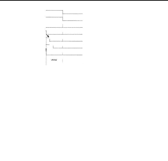
Press the emergency stop button immediately if a problem occurs with the system or line. The execution of all commands stops instantaneously when the emergency stop button is pressed. Servo power supply of the PC NC is shut OFF and dynamic brake is applied to stop all mechanical movement. In the emergency stop state, the PC NC is in the alarm state “3002”. If the emergency stop signal is “opened”, the PC NC stops the entire operation, and the SVMX and BKX signals are “opened”.
|
|
|
|
This operation is executed by setting the pins on the board. The pins differ between J300M |
||||
|
|
|
|
|||||
|
|
PC NC |
||||||
|
|
and J100M. |
|
|
|
|||
|
|
|
|
|
|
|
||
|
|
|
|
|
|
|
||
|
|
|
|
Table 1.2.1.1 |
Emergency Related Signals |
|||
|
|
|
|
|
|
|
|
|
|
|
|
|
|
|
Signal Name |
Pin Setting |
|
|
|
|
|
|
|
|
|
|
|
|
|
|
|
|
|
|
|
|
|
|
|
|
Emergency Stop Input |
CN12-19 pin on JZNC-JFC 10 board |
|
|
|
|
|
|
|
|
|
|
|
|
|
|
|
|
|
SVMX |
CN12-17 pin on JZNC-JFC 10 board |
|
|
|
|
|
|
|
|
|
|
|
|
|
|
|
|
BKX |
CN12-16 pin on JZNC-JFC 10 board |
|
|
|
|
|
|
|
|
|
|
1.2.2Overtravel
The overtravel function stops axis feed operation when an axis reaches the travel limit; for the detection of travel limit, a limit switch and a dog are used and if an axis reaches the travel limit, the limit switch outputs a signal and the function stops axis feed operation in response to this input. The axis reached and stopped at the travel limit can be moved manually into the axis movable range.
When the overtravel input is “opened”, axis movement is stopped in the manner as indicated in Table 1.2.2.1. In response to this input, the alarm output (ALM) is “closed” and the corresponding alarm message is displayed on the screen.
Table 1.2.2.1 |
Axis Stop Direction with Overtravel Input “Opened” |
||
|
|
|
|
|
|
Manual Operation Mode |
Automatic Operation Mode |
|
|
|
|
|
|
|
|
*+X to *+5 |
|
Movement in the *+X to *+5 |
|
input is “opened” |
|
direction is stopped. |
Movement of all axes is |
|
|
|
|
*-X to *-5 |
|
Movement in the *-X to *-5 |
stopped in all directions. |
|
|
||
input is “opened” |
|
direction is stopped. |
|
|
|
|
|
* Normally closed contact
1 - 9
YASNAC PC NC Operating Manual |
Chapter 1: Outline of the YASNAC System |
If the overtravel input is “opened”, select the manual mode (jog, pulse handle) and move the axis in the direction opposite to the direction for which the overtravel input is “opened” to “close” the input. After that press the [RESET] key on the NC operation panel, the alarm output and display are canceled.
1.After the occurrence of an alarm due to the “open” of the overtravel input, the M, S, and T code read output signals (MF, SF and TF) are not turned OFF.
2.If it is necessary to interrupt the operation called by M, S and/or T code, set the interlock by an external sequence.
3.The alarm numbers at the occurrence of overtravel are 2001 to 2005. If the overtravel alarm occurs, axis move is stopped. Note that the servo is not turned OFF.1
1.2.3Stored Stroke Limit
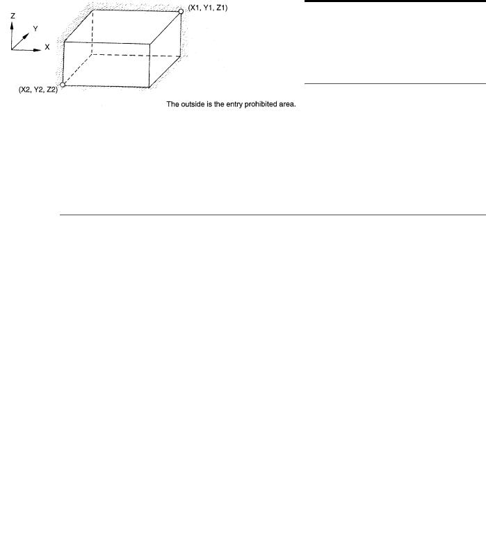
To ensure improved safety in operation, this function prevents axis from entering the preset entry prohibited areas both in manual and automatic operation.
(1) Stored Stroke Limit
To use the stored stroke limit function, the axis movable area is set by parameters with the coordinate values in the machine coordinate system. The area outside the set boundary is established as the entry prohibited area. If an axis enters the entry prohibited area, the function stops axis movement and displays an alarm message. The function is made valid upon completion of the manual reference point return after the power is turned ON. In automatic operation, if even one axis causes the alarm, all axis are stopped.
In manual operation, only the axis that caused an alarm is stopped.
Fig. 1.2.3.1 Stored Stroke Limit
1 - 10

YASNAC PC NC Operating Manual |
Chapter 1: Outline of the YASNAC System |
(2) Stored Stroke Limit B, C (G22, G23) *
The area either outside or inside the boundary set by parameters or by the commands in a program is established as the entry prohibited area. The boundary is set with the coordinate values in the machine coordinate system. Whether the entry prohibited area is established outside or inside the boundary can be determined by the setting for a parameter. The function is made valid upon completion of the reference point return after turning ON the power.
G CODE |
FUNCTION |
GROUP |
|
|
|
|
|
|
G22 |
Turning ON the stored stroke limit B |
04 |
|
|
|
G23 |
Turning OFF the stored stroke limit B |
04 |
|
|
|
Fig. 1.2.3.2 Stored Stroke Limit B Function
•In addition to the stored stroke limits A and B, stored stroke limit C can be added.
•With the stored stroke limit C, set the boundary of the area and inside or outside the boundary by parameters.
•According to the setting for the parameter or the input signal, one of the stored stroke limit C (third to fifth prohibited area) can be made valid.
•For details of the stored stroke limit B, C, refer to 4.2.3 “Stored Stroke Limit B and C (G22, G23)” in the PROGRAMMING MANUAL.
1 - 11
YASNAC PC NC Operating Manual |
Chapter 1: Outline of the YASNAC System |
1.2.4Interlock Inputs
The interlock input is the signal used to disable axis movement, and is provided for each axis.
•When an axis is interlocked during movement, it is stopped after deceleration.
•When the interlock is released, the axis continues moving to complete the remaining commands. Upon completion of the commands, the program advances to the next block.
•For simultaneous two or three axis interpolation commands, interpolation operation is disabled if one of these two or three axis is interlocked.
Fig. 1.2.4.1 |
Interlock Inputs |
1 - 12

YASNAC PC NC Operating Manual |
Chapter 2: PC NC System Outline |
2
PC NC System Outline
Chapter 2 describes various operations including power ON procedure, manual operation and automatic operation.
2.1 General Operation Flow . . . . . . . . . . . . . . . . . . . . . . . . . . . . . . . . . . . . . . . . . . . 2-2 2.2 Inspection Before Turning the Power ON . . . . . . . . . . . . . . . . . . . . . . . . . . . . . 2-3
2.2.1 Inspection of the NC Unit . . . . . . . . . . . . . . . . . . . . . . . . . . . . . . . . . . . 2-4 2.2.2 Preparation before Turning the Power ON . . . . . . . . . . . . . . . . . . . . . . . 2- 5 2.3 Turning the Power ON and Inspecting After Power ON . . . . . . . . . . . . . . . . . . 2-6
2.3.1 Procedure for Turning the Power ON . . . . . . . . . . . . . . . . . . . . . . . . . . 2-6 2.3.2 Checking the Motors for Abnormalities . . . . . . . . . . . . . . . . . . . . . . . . 2-7 2.3.3 Procedure for Turning Power OFF . . . . . . . . . . . . . . . . . . . . . . . . . . . . 2-7 2.3.4 Inspection of the Battery . . . . . . . . . . . . . . . . . . . . . . . . . . . . . . . . . . . . 2-8
2.4 Manual Operation (1) . . . . . . . . . . . . . . . . . . . . . . . . . . . . . . . . . . . . . . . . . . . . 2-11
2.4.1 Manual Rapid Traverse (RAPID) . . . . . . . . . . . . . . . . . . . . . . . . . . . . 2-11
2.4.2 Jog Feed (JOG) . . . . . . . . . . . . . . . . . . . . . . . . . . . . . . . . . . . . . . . . . . 2-11
2.4.3 Step Feed (STEP) . . . . . . . . . . . . . . . . . . . . . . . . . . . . . . . . . . . . . . . . . 2-12
2.4.4 Handle Feed (HANDLE)* . . . . . . . . . . . . . . . . . . . . . . . . . . . . . . . . . . 2-12
2.5 Manual Operation (2) . . . . . . . . . . . . . . . . . . . . . . . . . . . . . . . . . . . . . . . . . . . . 2-13
2.5.1 Simultaneous 2 or 3-axis Handle Feed * . . . . . . . . . . . . . . . . . . . . . . . 2-13 2.5.2 Manual Reference Point Return . . . . . . . . . . . . . . . . . . . . . . . . . . . . . . 2-14
2.5.3Manual Reference Point Return to the Second Reference Point* . . . . 2-16
2.5.4 1-line MDI . . . . . . . . . . . . . . . . . . . . . . . . . . . . . . . . . . . . . . . . . . . . . . 2-17
2.6 Automatic Operation (1) . . . . . . . . . . . . . . . . . . . . . . . . . . . . . . . . . . . . . . . . . 2-18
2.6.1 Preparation of Automatic Operation . . . . . . . . . . . . . . . . . . . . . . . . . . 2-18
2 - 1

YASNAC PC NC Operating Manual |
Chapter 2: PC NC System Outline |
2.6.2 MDI Operation . . . . . . . . . . . . . . . . . . . . . . . . . . . . . . . . . . . . . . . . . . . 2-21
2.6.3 Feed Hold . . . . . . . . . . . . . . . . . . . . . . . . . . . . . . . . . . . . . . . . . . . . . . . 2-21
2.6.4 Override . . . . . . . . . . . . . . . . . . . . . . . . . . . . . . . . . . . . . . . . . . . . . . . . 2-21
2.7 Automatic Operation (2) . . . . . . . . . . . . . . . . . . . . . . . . . . . . . . . . . . . . . . . . . 2-23
2.7.1 Optional Stop . . . . . . . . . . . . . . . . . . . . . . . . . . . . . . . . . . . . . . . . . . . . 2-23 2.7.2 Optional Block Skip . . . . . . . . . . . . . . . . . . . . . . . . . . . . . . . . . . . . . . . 2-23 2.7.3 Dry Run . . . . . . . . . . . . . . . . . . . . . . . . . . . . . . . . . . . . . . . . . . . . . . . . 2-24 2.7.4 Display Lock and Machine Lock . . . . . . . . . . . . . . . . . . . . . . . . . . . . . 2-24 2.7.5 Auxiliary Function Lock . . . . . . . . . . . . . . . . . . . . . . . . . . . . . . . . . . . 2-25 2.7.6 Z-axis Command Neglect . . . . . . . . . . . . . . . . . . . . . . . . . . . . . . . . . . 2-25 2.7.7 4th-axis Command Neglect . . . . . . . . . . . . . . . . . . . . . . . . . . . . . . . . . 2-25 2.7.8 5th-axis Command Neglect . . . . . . . . . . . . . . . . . . . . . . . . . . . . . . . . . 2-26
2.8 Operation Intervention During Automatic Operation . . . . . . . . . . . . . . . . . . . 2-27
2.8.1 MDI Operation Intervention during Automatic Operation . . . . . . . . . 2-28 2.8.2 Automatic Handle Mode Offset * . . . . . . . . . . . . . . . . . . . . . . . . . . . . 2-28 2.8.3 Manual Absolute . . . . . . . . . . . . . . . . . . . . . . . . . . . . . . . . . . . . . . . . . 2-30
2 - 2

YASNAC PC NC Operating Manual |
Chapter 2: PC NC System Outline |
2.1General Operation Flow
The operation procedure usually followed for daily operation is indicated in Fig.2.1.1. This chapter explains these operation items.
Setting Part Program
Loading NC program from PC by Ethernet or from touch screen and executing the Program numbers
|
|
|
Fig. 2.1.1 |
Operation Procedure |
|
2 - 3

YASNAC PC NC Operating Manual |
Chapter 2: PC NC System Outline |
2.2Inspection Before Turning the Power ON
Before turning the power ON for YASNAC PC NC, it is necessary to carry out inspection to Ensure safety. If the power is turned ON while the system has trouble, it could cause malfunctioning of the system itself and create a hazards conditions for the operations. Make sure to carryout daily inspection before turning the power ON.
WARNING!
•Always turn all power OFF (including the primary power supply) before carrying out daily inspection.
Performing the inspection with the power ON may lead to electric shock.
•Wait 5 minutes after turning the power (including the primary power supply) OFF before removing or replacing any unit or part.
•Failure to observe this warning could lead to electric shock and equipment failure.
•Do not touch any unit, terminals, etc., while the power is ON.
Failure to observe this warning could lead to electric shock or device malfunction.
•Immediately after switching the power OFF, the product retains some electric charge. Do not touch any parts (which are live when the power is ON) for 5 minutes after switching the power OFF.
Failure to observe this warning could lead to electric shock or device malfunction.
•Do not damage cables, subject them to excessive stress, or pinch them.
Excessive load on cables may cause electric shock.
•When the equipment is powered ON, never touch its rotating parts.
Failure to observe this warning could result in personal injury.
•Never modify the product.
2 - 4

YASNAC PC NC Operating Manual |
Chapter 2: PC NC System Outline |
|
|
CAUTION!
•To prevent personnel other than those involved in maintenance and inspection work from turning the power ON while maintenance and inspection is in progress, place signs stating “DO NOT TURN THE POWER ON” or words to that effect at the primary power supplies of related control panels and other relevant locations.
Failure to observe this caution could lead to electric shock.
•Electronic devices such as CMOS ICs are used on the control boards. If you touch the IC’s with your bare fingers, static electrical charge in your body could destroy these IC’s, care must be taken when handling these devices. Before handling these devices for maintenance purposes, first discharge the static electricity in your body by touching a grounded metal device.
Failure to observe this caution could lead to personal injury and product failure.
•Do not install or remove boards, wiring, connectors, etc., while the power is ON.
Failure to observe this caution could lead to electric shock, product failure, and malfunction.
•Do not let foreign matter such as electrical wire scrap enter the unit.
Failure to observe this caution could result in fire, product failure or malfunction.
•Be sure to check the following points after completing maintenance and inspection work:
•Check that all fastening bolts are tightened.
•Check that no tools or other objects have been left inside the control panel.
•Check that the control panel door is closed properly.
Failure to carry out these checks could lead to electric shock, injuries, fire, and malfunction.
•Never attempt to disassemble the NC unit modify units/devices inside the PC NC unit.
Failure to observe this caution could lead to fire, product failure and malfunction.
•Do not change the set values of the devices, variable resistors, etc., in the control panel.
Failure to observe this caution could lead to fire, product failure, and malfunction.
2.2.1Inspection of the NC Unit
In this subsection, the items to be inspected before turning ON the power are indicated for the standard PC NC box supplied by Yaskawa. For the machine tool’s control box, refer to the machine tool manuals.
(1)Inspecting the Machine Cabinet Doors
Make sure that the doors are securely closed before turning the power ON. The PC NC CPU rack is not protected against oil mists or other airborne foreign matter. The door of the machine cabinet doors must always be kept closed before powering ON.
2 - 5

YASNAC PC NC Operating Manual |
Chapter 2: PC NC System Outline |
(2)Inspecting the Shielding Parts in the Machine Cabinet
Inspect the shielding parts in the Machine Cabinet every month for gaps and/or damage.
Open the doors and check the packings installed around the door for damage.
Inspect the inside of the Machine Cabinet for abnormal contamination. If the inside is abnormally dirty, clean it immediately after locating the cause of contamination.
Lock the doors securely and inspect the doors to make sure that there are no gaps.
By carrying out the inspection procedures indicated above at regular intervals, the YASNAC PC NC can perform efficiently for a long time.
2.2.2Preparation before Turning the Power ON
Before turning the power ON, confirm the following conditions:
•Make sure that the front side of the PC NC unit is closed. If the door is open or if there is a gap between the door and the box panels, securely close and lock the door.
•Carry out the inspection for the machine and machine related controllers according to the instructions in the machine tool manuals.
2 - 6

YASNAC PC NC Operating Manual |
Chapter 2: PC NC System Outline |
2.3Turning the Power ON and Inspecting After Power ON
In this section, the procedure to be used for turning the power ON is explained. Inspection that must be conducted after turning the power ON is also described.
WARNING!
•Be sure to turn the power OFF before replacing the battery.
Failure to observe this warning could lead to electric shock and product failure.
CAUTION!
•Replace fuses and batteries with the recommended products.
Failure to observe this caution could result in fire or product failure.
•Use the product with the “System Number Switch” of the CPU set to “0”.
Using while set to another number could lead to malfunction.
•Wait at least 2 seconds after turning the power OFF before turning it ON again.
Failure to observe this caution could lead to malfunction.
2.3.1Procedure for Turning the Power ON
Turn the power ON in the following sequence.
Make sure that the power supplied to the PC NC unit is from an external power source.
Press the POWER ON button on the NC operation panel. Control power is turned ON and the cooling fan starts rotating.
Make sure that air is flowing out at the upper part on the side of the NC unit.
•In approximately 20 seconds, the control is ready for turning ON the servo power (alarm code 3000).
Press the POWER ON button again - one time.
•The servo power is turned ON. When the machine is ready for operation, the NC enters the ready state.
•When the power is correctly turned ON to the NC unit, the NRD (NC ready) signal is output.
•When the power is turned ON at the machine side in response to the NRD signal, the MRD (machine ready) signal will be returned to the NC. The READY lamp goes on when the MRD signal is returned. Note that a READY lamp is not used with some types of machines.
2 - 7

YASNAC PC NC Operating Manual |
Chapter 2: PC NC System Outline |
•When the NC unit enters the ready state, the alarm message (displayed on the screen) will go off.
If the NC unit fails to enter the ready state, locate the cause by referring to Section 7.2, “ALARM DISPLAY JOB”, and take appropriate steps. For turning the power ON, there are items that must be inspected at the machine side in addition to the NC unit related items. For the former items, refer to the machine tool manuals.
5
PC NC Boots MMI screens
Fig. 2.3.1.1 Power ON Sequence
2.3.2Checking the Motors for Abnormalities
Check the operation of the motors running. If abnormal vibration or noise occurs, turn the power OFF and contact the maintenance personnel.
2.3.3Procedure for Turning Power OFF
Turn the power OFF in the following sequence:
Make sure that the CYCLE START lamp on the machine operation panel is OFF with the machine stopped.
Make sure that there is no alarm message displayed on the CRT screen. If an alarm message is displayed, locate the cause by referring to Chapter 4, “MAINTENANACE” and take appropriate measures to clear it.
Carry out necessary STEPS for turning the power OFF at the machine side. For details, refer to the machine tool manuals.
Press the EMERGENCY STOP button on the machine operation panel to turn the servo power OFF.Press SHUTDOWN button to close all opened windows of PC NC.
When the safe SHUTDOWN message is displayed on CRT, Press the POWER OFF button on the NC operation panel to shut off the power to PC NC.
2 - 8
YASNAC PC NC Operating Manual |
Chapter 2: PC NC System Outline |
Turn the power supply to the NC OFF by turning OFF a circuit breaker, etc.
PC NC Control Power Supply
PC NC Display
Shut Down button
Shut Down of PC Side
Closing Windows NT
Safe to Turn Off Windows NT
Fig. 2.3.3.1 Power OFF Sequence
2.3.4Inspection of the Battery
After turning the power ON, if there is a battery alarm, a broken battery icon will be displayed, or a solid battery is displayed to indicate everything is normal. After two minutes this normal battery indicator will disappear. When battery alarm is displayed by red battery icon, the battery must be replaced immediately. Standard batteries cannot be used. For a replacement of battery, contact your Yaskawa representative for Battery type: ER6VC3, Parts code: BA510
(1)Checking the Battery Which Needs Replacing
Follow the procedure indicated below to determine whether or not battery must be replaced.
Press the POWER OFF button.
If a door interlock switch is installed, place the door interlock key in the OFF position. This makes a power ON condition possible with the door opened.
Open the door so that the front part of the PC NC unit is visible.
Press the POWER ON button again - once.
2 - 9
Loading...