


 Loading...
YASKAWA
VARISPEED-656DC5
INSTRUCTION MANUAL
PWM TRANSISTOR CONVERTER
MODEL: CIMR-D5A 
200 to 230 V, 27 to 120 HP (20 to 90 kW) 380 to 460 V, 27 to 496 HP (20 to 370 kW)
Upon receipt of the product and prior to initial operation, read these instructions thoroughly, and retain for future reference.
YASKAWA |
MANUAL NO. TOBP C710656 00C |

Copyright © 2004 YASKAWA ELECTRIC CORPORATION
All rights reserved. No part of this publication may be reproduced, stored in a retrieval system, or transmitted, in any form, or by any means, mechanical, electronic, photocopying, recording, or otherwise, without the prior written permission of Yaskawa. No patent liability is assumed with respect to the use of the information contained herein. Moreover, because Yaskawa is constantly striving to improve its high-quality products, the information contained in this manual is subject to change without notice. Every precaution has been taken in the preparation of this manual. Nevertheless, Yaskawa assumes no responsibility for errors or omissions. Neither is any liability assumed for damages resulting from the use of the information contained in this publication.
PREFACE
YASKAWA’s VARISPEED-656DC5 is a PWM transistor converter. This instruction manual describes installation, maintenance and inspection, troubleshooting, and specifications of the VS-656DC5. Read this instruction manual thoroughly before operation.
YASKAWA ELECTRIC CORPORATION
General Precautions
•Some drawings in this manual are shown with the protective cover or shields removed, in order to describe detail with more clarity. Make sure all covers and shields are replaced before operating this product.
•This manual may be modified when necessary because of improvement of the product, modification, or changes in specifications.
Such modifications are denoted by a revised manual No.
•To order a copy of this manual, if your copy has been damaged or lost, contact your YASKAWA representative.
•YASKAWA is not responsible for any modification of the product made by the user, since that will void your guarantee.
SAFETY INFORMATION

 WARNING

 CAUTION
Read this instruction manual thoroughly before installation, operation, maintenance or inspection of the VS-656DC5. In this manual, NOTES FOR SAFE OPERATION are classified as “WARNING” or “CAUTION.”
Indicates a potentially hazardous situation which, if not avoided, could result in death or serious injury to personnel.
Indicates a potentially hazardous situation which, if not avoided, may result in minor or moderate injury to personnel and damage to equipment.
It may also be used to alert against unsafe practices.
Even items described in 
 CAUTION may result in a vital accident in some situations. In either case, follow these important notes.
NOTE
These are steps to be taken to insure proper operation.
iii
NOTES FOR SAFE OPERATION
RECEIVING
|
CAUTION |
|
|
|
|
|
|
(Ref. Page) |
|
• Do not install or operate any VS-656DC5 which is damaged or has missing parts. |
E-3 |
|
Failure to observe this caution may result in personal injury or equipment damage. |
|
|
|
|
INSTALLATION |
|
|
|
|
|
|
CAUTION |
|
•Lift the cabinet by the base. When moving the VS-656DC5, never lift by the front cover or the front panel.
Otherwise, the main unit may be dropped causing personal injury or damage to the VS656DC5.
•Mount the VS-656DC5 on nonflammable material (i.e. metal).
Failure to observe this caution may result in a fire.
•When mounting several Units in an enclosure, install a fan or other cooling device to keep the intake air temperature below 45 °C.
Overheating may cause a fire or damage to the VS-656DC5.
(Ref. Page)
E-5
E-5
E-5
iv

WIRING
 WARNING
•Only commence wiring after verifying that the power supply is tunred OFF.
Failure to observe this warning may result in an electric shock or a fire.
•Wiring should be performed only by qualified personnel.
Failure to observe this warning may result in an electric shock or a fire.
•Make sure to ground the ground terminal  before connecting the other terminals. (200 V class: Ground to 100 Ω or less, 400 V class: Ground to 10 Ω or less).
Failure to observe this warning may result in an electric shock or a fire.
(Ref. Page)
E-11
E-11
E-11
 CAUTION
•Verify that the VS-656DC5 rated voltage coincides with the AC power supply voltage.
Failure to observe this caution may result in personal injury or a fire.
•Do not perform a withstand voltage test of the VS-656DC5.
Failure to observe this caution may result in damage to the semi-conductor elements.
•Connect the input AC reactor, harmonics filter reactor, and the harmonics filter capacitor as described in this instruciton manual.
Failure to observe this caution may result in a fire.
•Verify that the rated voltage of the VS-656DC5 coincides with the rated voltage of the Inverter to be connected.
Failure to observe this caution may result in a fire.
•Tighten terminal screws.
Failure to observe this caution may result in a fire.
(Ref. Page)
E-11
E-11
E-11
E-11
E-11
v

OPERATION
 WARNING
•Only turn ON the input power supply after attaching the front cover or the terminal cover. Do not remove the cover while current is flowing.
Failure to observe this warning may result in an electric shock.
•Never operate the Digital Operator or other switches when your hand is wet.
Failure to observe this warning may result in an electric shock.
•Never touch the terminals while current is flowing, even if the VS-656DC5 stops.
Failure to observe this warning may result in an electric shock.
(Ref. Page)
E-30
E-30
E-30
 CAUTION
•Never touch the radiation fins (heatsink) or input reactor since the temperature is very high.
Failure to observe this caution may result in harmful burns to the body.
•The VS-656DC5 is factory set to the suitable settings. Do not change the settings unnecessarily.
Failure to observe this caution may result in damage to the unit.
(Ref. Page)
E-30
E-30
vi
MAINTENANCE AND INSPECTION
 WARNING
•Never touch high-voltage terminals in the VS-656DC5.
Failure to observe this warning may result in an electric shock.
•Perform maintenance or inspection only after verifying that the CHARGE LED goes OFF, after the main circuit power supply is turned OFF.
The capacitors are still charged and can be dangerous.
•Only authorized personnel should be permitted to perform maintenance, inspections, or parts replacement.
[Remove all metal objects (watches, bracelets, etc.) before operation.] (Use tools which are insulated against electric shock.)
Failure to observe this warning may result in an electric shock.
(Ref. Page)
E-39
E-39
E-39
 CAUTION
|
(Ref. Page) |
• A CMOS IC is used in the control board. Handle the control board and CMOS IC |
E-39 |
carefully. The CMOS IC can be destroyed by static electricity if touched directly. |
|
The CMOS IC may be destroyed by static electricity if touched directly. |
|
• Do not change the wiring, or connect/disconnect the connectors while power is |
E-39 |
applied to the circuit. |
|
Failure to observe this caution may result in personal injury.
OTHERS
WARNING |
|
|
|
|
(Ref. Page) |
• Never modify the product. |
E-39 |
Failure to observe this warning may result in an electric shock or personal injury. |
|
|
|
 CAUTION
|
(Ref. Page) |
• Do not subject the VS-656DC5 to halogen gases, such as fiuorine, chlovine, bro- |
E-39 |
mine, and iodine, at any time even during transportation or installation. |
|
Otherwise, the VS-656DC5 can be damaged or interior parts burnt. |
|
vii
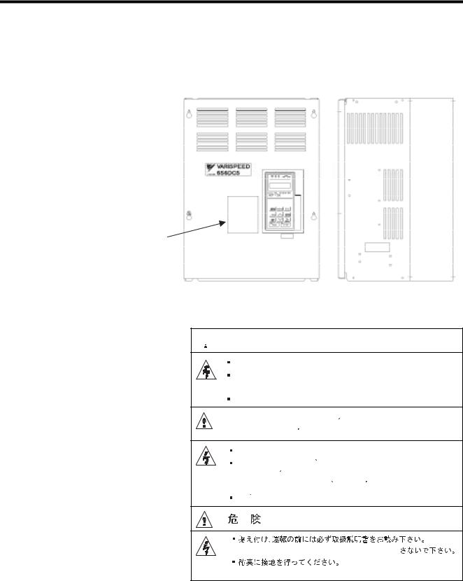
Warning Label Position
A warning label is displayed on the front cover of the VS-656DC5, as shown below. Follow these instructions when handling the VS-656DC5.
Warning
Label
Warning Label
 WARNING − Risk of electric shock.
Read manual before installing.
Wait 5 minutes for capacitor discharge after disconnecting power supply.
Use proper grounding techniques.
AVERTISSMENT - Risque de decharge electrique.
Lisez le manuel avant installation.
Attendez 5 minutes apres la coupure de l’ alimentation electrique afin que les condensateurs soient completement decharges.
Soyez a la masse par une bonne technique.
- 


 5
5


NPJT31393-1-0
viii

WARRANTY INFORMATION
Warranty Period
This product is warranted for twelve months after being delivered to Yaskawa’s customer or if applicable eighteen months from the date of shipment from Yaskawa’s factory, whichever comes first.
Scope of Warranty
Inspections
Periodic inspections must be conducted by the customer. However, upon request, Yaskawa or one of Yaskawa’s Service Centers can inspect the product for a fee. In this case, if after conferring with the customer, a Yaskawa product is found to be defective due to Yaskawa workmanship or materials and the defect occurs during the warranty period, then this fee will be waived and the problem remedied free of charge.
Repairs
If a Yaskawa product is found to be defective due to Yaskawa workmanship or materials and the defect occurs during the warranty period, Yaskawa will provide a replacement, repair the defective product, and provide shipping to and from the site free of charge.
However, if the Yaskawa Authorized Service Center determines that the problem with a Yaskawa product is not due to defects in Yaskawa’s workmanship or materials, then the customer will be responsible for the cost of any necessary repairs. Some problems that are outside the scope of this warranty are:
•Problems due to improper maintenance or handling, carelessness, or other reasons where the customer is determined to be responsible.
•Problems due to additions or modifications made to a Yaskawa product without Yaskawa’s understanding.
•Problems due to the use of a Yaskawa product under conditions that do not meet the recommended specifications.
•Problems caused by natural disaster or fire.
•Or other problems not due to defects in Yaskawa workmanship or materials.
Warranty service is only applicable within Japan.
However, after-sales service is available for customers outside of Japan for a reasonable fee. Contact your local Yaskawa representative for more information.
Exceptions
Any inconvenience to the customer or damage to non-Yaskawa products due to Yaskawa's defective products whether within or outside the warranty period are NOT covered by this warranty.
ix

RESTRICTIONS
•The VS-656DC5 was not designed or manufactured for use in devices or systems that may directly affect or threaten human lives or health.
•Customers who intend to use the product described in this manual for devices or systems relating to transportation, health care, space aviation, atomic or electric power, or underwater use must contact their Yaskawa representatives or the nearest Yaskawa sales office beforehand.
•This product has been manufactured under strict quality-control guidelines. However, if this product is to be installed in any location where failure of this product could involve or result in a life-and-death situation or loss of human life or in a facility where failure may cause a serious accident or physical injury, safety devices must be installed to minimize the likelihood of any accident.
x
INSTRUCTIONS
Varispeed-656DC5
1 RECEIVING - - - - - - - - - - - - - - - - - - - - - - - - - - - - - - - - - - E-3
1.1 Checks - - - - - - - - - - - - - - - - - - - - - - - - - - - - - - - - - - - - - - E-3
1.2 Nameplate Information - - - - - - - - - - - - - - - - - - - - - - - - - - - E-3
2 INSTALLATION - - - - - - - - - - - - - - - - - - - - - - - - - - - - - - - E-5
2.1 Checking Installation Site - - - - - - - - - - - - - - - - - - - - - - - - - E-5
2.2 Clearances - - - - - - - - - - - - - - - - - - - - - - - - - - - - - - - - - - - E-6
2.3 Dimensions - - - - - - - - - - - - - - - - - - - - - - - - - - - - - - - - - - - E-7
2.4 Removing/Attaching the Digital Operator - - - - - - - - - - - - - - E-9
2.5 Removing/Attaching the Front Cover - - - - - - - - - - - - - - - - E-10
3 WIRING - - - - - - - - - - - - - - - - - - - - - - - - - - - - - - - - - - - - -E-11
3.1 Connection and Specifications of Peripheral Devices - - - - E-12 3.2 External Dimensions of Peripheral Devices - - - - - - - - - - - E-14 3.3 Interconnection Diagram with Varispeed G7 - - - - - - - - - - - E-18 3.4 Interconnection Diagram with VS-616G5 - - - - - - - - - - - - - E-20 3.5 Wiring Precautions - - - - - - - - - - - - - - - - - - - - - - - - - - - - E-22 3.6 WIRING MAIN CIRCUIT TERMINALS - - - - - - - - - - - - - - - E-24 3.7 EXTERNAL TERMINALS - - - - - - - - - - - - - - - - - - - - - - - - E-28
4 OPERATION - - - - - - - - - - - - - - - - - - - - - - - - - - - - |
- - - - E-30 |
|
4.1 |
Checkpoints before Turning ON the Power Supply - |
- - - - - E-30 |
4.2 |
Setting the Power Supply Voltage Jumper |
|
|
(For 400 V Class VS-656DC5 with 22 kW or More) |
- - - - - E-31 |
4.3 |
Using the Digital Operator - - - - - - - - - - - - - - - - - - |
- - - - - E-32 |
4.4 |
Power ON/OFF Sequence - - - - - - - - - - - - - - - - - - - |
- - - - E-38 |
E-1

5 MAINTENANCE AND INSPECTION - - - - - - - - - - - - - - - - E-39
5.1 Maintenance Period - - - - - - - - - - - - - - - - - - - - - - - - - - - - E-39
5.2 Daily Inspection - - - - - - - - - - - - - - - - - - - - - - - - - - - - - - - E-40
5.3 Periodic Inspection - - - - - - - - - - - - - - - - - - - - - - - - - - - - E-40
5.4 PERIODIC MAINTENANCE OF PARTS - - - - - - - - - - - - - E-41
6 TROUBLESHOOTING - - - - - - - - - - - - - - - - - - - - - - - - - - E-42
6.1 |
Fault Detection - - - - - - - - - - - - - - - - - - - - - - - - - - - - - - - |
E-42 |
6.2 |
Minor Fault Detection - - - - - - - - - - - - - - - - - - - - - - - - - - - |
E-45 |
6.3 |
Operation Errors - - - - - - - - - - - - - - - - - - - - - - - - - - - - - - |
E-46 |
6.4 |
Informing the VS-656DC5 of a Peripheral Device Fault |
|
|
to Stop the VS-656DC5 (External Fault Function) - - - - - - |
E-47 |
7 SPECIFICATIONS - - - - - - - - - - - - - - - - - - - - - - - - - - - - - E-48
Appendix A CONSTANTS LIST - - - - - - - - - - - - - - - - - - - - - E-50
A.1 |
Monitor Constant List - - - - - - - - - - - - - - - - - - - - - - - - - - |
E-50 |
A.2 |
Constant List Other Than Monitor Constants - - - - - - - - - - |
E-54 |
A.3 |
Multi-function I/O Terminals (H Constants) - - - - - - - - - - - |
E-57 |
Appendix B PRECAUTIONS ON VS-656DC5 |
|
|
|
APPLICATION - - - - - - - - - - - - - - - - - - - - - - - - |
E-58 |
E-2
1 RECEIVING
1 RECEIVING
 CAUTION
•Do not install or operate any VS-656DC5 which is damaged or has missing parts.
Failure to observe this caution may result in personal injury or equipment damage.
This chapter describes how to verify the VS-656DC5 after delivery to the user.
1.1 |
Checks |
|
|
|
|
|
|
Table 1 Checks |
|
|
|
|
|
|
|
|
Item |
|
Method |
|
|
|
|
|
|
|
Does the VS-656DC5 model number |
|
Check the model number on the nameplate on the side of the |
|
|
correspond with the purchase order? |
|
VS-656DC5. (Refer to page E-4.) |
|
|
|
|
|
|
|
Are any parts damaged? |
|
Visually check the exterior and verify that there was no dam- |
|
|
|
|
age during transport. |
|
|
|
|
|
|
|
Are any screws or other components loose? |
|
Use a screwdriver or other tools to check for tightness. |
|
|
|
|
|
If any of the above items are not satisfactory, contact your YASKAWA representative.
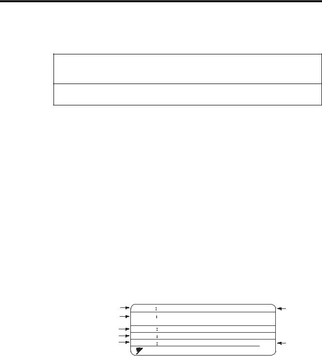
1.2Nameplate Information
Nameplate Example
The following nameplate is an example for a standard domestic (Japan) VS-656DC5: 3-phase, 400 VAC, 30 kW, IEC IP00.
Converter Unit |
MODEL |
CIMR-D5A4030 |
|
|
Converter |
|
model |
|
|
||||
Input Specification |
INPUT |
AC3PH 380 |
- 460V |
50Hz |
|
Unit |
|
specifications |
|||||
|
|
380 |
- 460V |
60Hz |
64A |
|
Output Specification |
|
|
||||
OUTPUT |
DC660V |
|
|
60A |
|
|
LOT number |
SPEC |
40300A |
|
|
|
|
Serial No. |
SER NO |
|
|
|
MASS: 33kg |
Mass |
|
YASKAWA ELECTRIC CORPORATION |
MADE IN JAPAN |
|
|||
Fig. 1 Nameplate
E-3

VS-656DC5 Model Number and Specifications
CIMR − D5 A 4 030 0
Converter Unit 
|
|
|
VS-656DC5 series |
|
|
||
|
|
|
|
|
|
|
|
Symbol |
|
|
Specifications |
|
|
||
|
|
|
|
||||
A |
|
Japan standard model |
|
|
|||
|
|
|
|
|
|
|
|
|
|
Symbol |
Voltage Class |
|
|
|
|
|
|
|
|
||||
|
2 |
|
3-phase, 200 V |
|
|
|
|
|
4 |
|
3-phase, 400 V |
|
|
|
|
|
|
|
|
|
|
|
|
|
|
|
|
|
|
|
|
Symbol |
|
Protective Structure |
|
|
|
|
|
|
|
||||
|
|
|
|
|
0 |
Open chassis (IEC IP00)* |
|
||
|
|
|
|
|
|
|
|
|
|
|
|
|
|
|
|
Symbol |
|
Max. Applicable Inverter Output |
|
|
|
|
|
|
|
|
|||
|
|
|
|
015 to 300 |
15 to 300 kW |
||||
*Protected so that parts of the human body cannot reach electrically charged parts from the front when the VS-656DC5 is mounted in a control panel.
Fig. 2 VS-656DC5 Model Number and Specifications
E-4

2 INSTALLATION
2 INSTALLATION
 CAUTION
•Lift the cabinet by the base. When moving the VS-656DC5, never lift by the front cover or the front panel.
Otherwise, the main unit may be dropped causing personal injury or damage to the VS-656DC5.
•Mount the VS-656DC5 on nonflammable material (i.e. metal).
Failure to observe this caution may result in a fire.
•When mounting several Units in an enclosure, install a fan or other cooling device to keep the intake air temperature below 45 °C.
Overheating may cause a fire or damage to the VS-656DC5.
This chapter describes the configuration, location, and space when mounting the VS-656DC5.
2.1Checking Installation Site
Installation Site
Install the VS-656DC5 under the following conditions.
Type |
Ambient Operating Temperature |
Humidity |
|
|
|
Open chassis |
-10 to + 45 °C |
90 % RH or less (no condensation) |
|
|
|
To ensure proper performance and long operating life, follow the recommendations below when choosing a location for installing the VS-656DC5. Make sure the VS-656DC5 is protected from the following conditions:
• Extreme cold and heat
Use only within ambient temperature range: -10 °C to +45 °C
•Rain, moisture
•Oil sprays, splashes
•Salt spray
•Direct sunlight (Avoid using outdoors.)
•Corrosive gases or liquids
•Dust or metallic particles in the air
•Physical shock, vibration
•Magnetic noise (Example: welding machines, power devices, etc.)
•High humidity
•Radioactive materials
•Combustibles: thinners, solvents, etc.
E-5
Controlling the Ambient Temperature
To enhance the reliability of operation, the VS-656DC5 should be installed in an environment free from extreme temperature increases. If the VS-656DC5 is installed in an enclosed environment, such as a box, use a cooling fan or air conditioner to maintain the internal air temperature below 45 °C.
Protecting the VS-656DC5 from Foreign Matter
Place a cover over the VS-656DC5 during installation to shield it from metal powder produced by drilling.
Always remove the cover from the VS-656DC5 after completing installation. Otherwise, ventilation will be reduced, causing the VS-656DC5 to overheat.
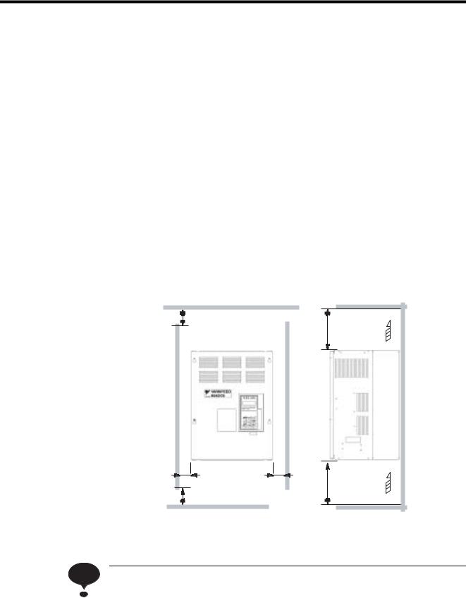
2.2Clearances
Install the VS-656DC5 vertically and allow sufficient clearances for effective cooling as shown in Fig. 3.
50 mm or more |
|
30mm or more |
30 mm |
50 mm or more |
or more |
|
Air
120 mm or more
120 mm or more Air
(a) Front View |
(b) Side View |
Fig. 3 |
Clearances |
NOTE |
When installing the open chassis type of 200 V/400 V 30 kW or more, extra spacing will be required |
|
|
|
on either side for eyebolts or main circuit wiring. |
|
|
E-6
2 INSTALLATION
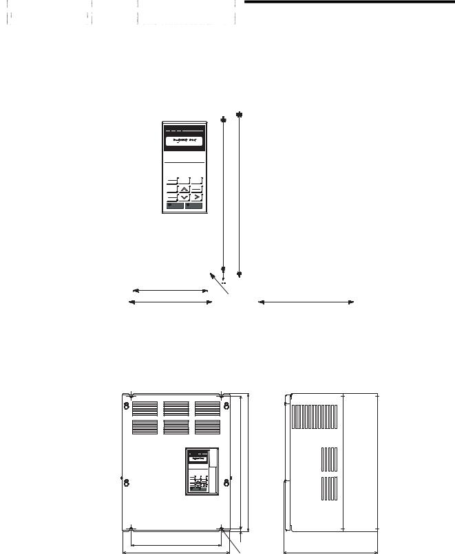
2.3Dimensions
Models of 200 V/400 V 15 kW or Less
The following figure shows a 200 V 15 kW model.
DRIVE FWD REV |
REMOTE |
SEQ 
 REF
REF
U1 01 = 00.00 HZ
DIGITAL OPERATOR
JVOP - 130
LOCAL
MENU ESC
REMOTE
JOG |
DATA |
|
ENTER |
FWD |
|
REV |
RESET |
RUN |
STOP |
W1
W
H1 |
H |
 H2
H2
4-d
Fig. 4 Dimensions of VS-656DC5
Models of 200 V/400 V 22 kW or More
The following figure shows a 200 V 22 kW model.
DRIVE FWD REV |
REMOTE |
U1 01 = |
00.00 HZ |
LOCAL |
MENU |
H1 |
H |
ESC |
|
||
REMOTE |
|
||
JOG |
|
DATA |
|
|
ENTER |
|
|
FWD |
|
|
|
REV |
|
RESET |
|
RUN |
|
STOP |
|
W1
W
H2
D
4-d
E-7

Table 2 VS-656DC5 External Dimensions and Approx. Masses
|
|
|
|
|
|
|
|
|
Unit: mm |
|
Voltage |
VS-656DC5 |
|
|
|
Open Chassis (IP00) |
|
|
|||
Class |
Model |
|
|
|
|
|
|
|
|
|
W |
H |
D |
W1 |
H1 |
H2 |
Approx. |
Mount- |
|||
|
CIMR- |
|||||||||
|
|
|
|
|
|
|
Mass |
ing |
||
|
D5A |
|
|
|
|
|
|
|||
|
|
|
|
|
|
|
[kg] |
Hole d |
||
|
|
|
|
|
|
|
|
|||
|
|
|
|
|
|
|
|
|
|
|
200 V |
2015 |
250 |
380 |
225 |
236 |
365 |
7.5 |
11 |
M6 |
|
Class |
|
|
|
|
|
|
|
|
|
|
2022 |
325 |
450 |
285 |
275 |
435 |
7.5 |
23 |
M6 |
||
|
||||||||||
|
|
|
|
|
|
|
|
|
|
|
|
2037 |
425 |
725 |
350 |
320 |
700 |
12.5 |
47 |
M10 |
|
|
|
|
|
|
|
|
|
|
|
|
|
2055* |
475 |
800 |
350 |
370 |
775 |
12.5 |
65 |
M10 |
|
|
2075 |
575 |
925 |
400 |
445 |
895 |
15.0 |
135 |
M12 |
|
|
|
|
|
|
|
|
|
|
|
|
400 V |
4015 |
250 |
380 |
225 |
236 |
365 |
7.5 |
11 |
M6 |
|
Class |
|
|
|
|
|
|
|
|
|
|
4022 |
325 |
450 |
285 |
275 |
435 |
7.5 |
26 |
M6 |
||
|
|
|
|
|
|
|
|
|
|
|
|
4030 |
325 |
625 |
285 |
275 |
610 |
7.5 |
33 |
M6 |
|
|
|
|
|
|
|
|
|
|
|
|
|
4045 |
|
|
|
|
|
|
36 |
M6 |
|
|
|
|
|
|
|
|
|
|
|
|
|
4075 |
455 |
820 |
350 |
350 |
795 |
12.5 |
60 |
M10 |
|
|
|
|
|
|
|
|
|
|
|
|
|
4160 |
575 |
925 |
400 |
445 |
895 |
15.0 |
117 |
M12 |
|
|
|
|
|
|
|
|
|
|
|
|
|
4300* |
|
|
|
|
− |
|
|
|
|
* Contact your YASKAWA representative.
Note: An attachment is required to mount the cooling fins (fin section) on the outside of the control panel for 200 V/400 V class VS-656DC5 of 15 kW or less. Contact your YASKAWA representative for details.
For dimensional drawings for models with externally mounted cooling fins or other special requirements, contact your YASKAWA representative.
E-8
2 INSTALLATION
2.4Removing/Attaching the Digital Operator
Remove and attach the Digital Operator as follows.
Removing the Digital Operator
2
Front cover 
|
|
|
|
Push the Digital Operator lever in the direction |
|
|
|
|
|
shown by arrow 1 and lift the Digital Operator in |
|
|
|
|
|
||
Digital Operator |
1 |
the direction shown by arrow 2 to remove the Digital |
|||
Operator from the front cover. |
|||||
|
|
|
|||
Fig. 5 Removing the Digital Operator
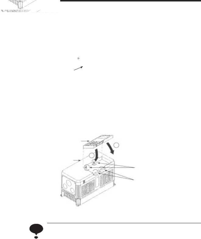
Attaching the Digital Operator
Digital Operator |
|
Attach the Digital Operator on claws A in |
|
2 |
|
|
the direction shown by arrow 1 and then on |
|
|
|
|
|
|
claws B in the direction shown by arrow 2, to |
1 |
|
lock the Digital Operator. |
Front cover
Claws A
Claws B
Fig. 6 Attaching the Digital Operator
NOTE |
Never attach the Digital Operator in any other direction or by any other method, as faulty contact may |
|
result. |
|
|
E-9
2.5Removing/Attaching the Front Cover
Models of 15 kW or Less
To remove the front cover, first remove the Digital Operator in the direction shown by arrow 1. (Refer to 2.4 Removing/Attaching the Digital Operator.) Then squeeze the cover in the direction shown by arrows 2 on both sides and lift in the direction shown by arrow 3.
1
Front cover
2
3
2
Fig. 7 Removing/Attaching the Front Cover (15 kW or Less)
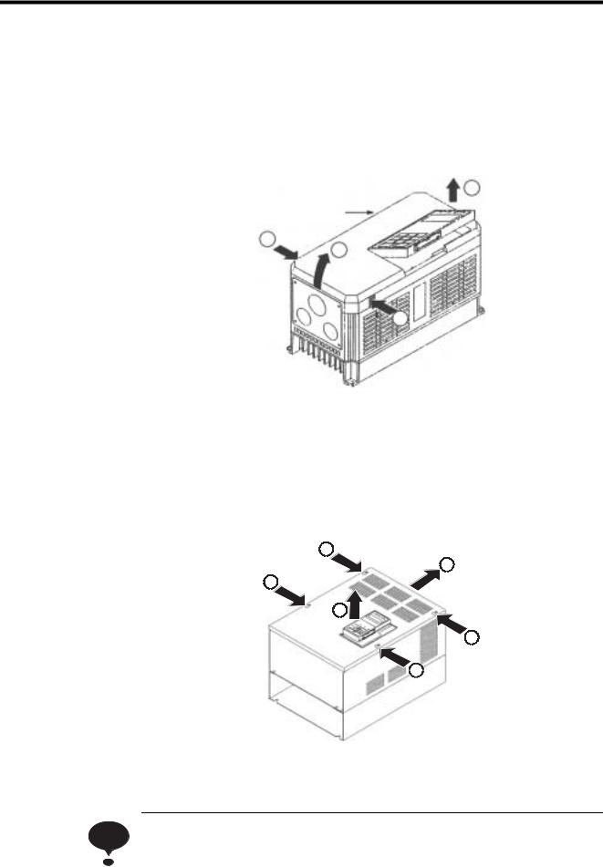
Models of 22 kW or More
To remove the front cover, first remove the Digital Operator in the direction shown by arrow 1. (Refer to 2.4 Removing/Attaching the Digital Operator.)
Then loosen the four screws shown by arrow 2 and slide the front cover in the direction shown by arrow 3.
2
3
2
1
2
2
Fig. 8 Removing/Attaching the Front Cover (22 kW or More)
NOTE |
Do not attach the front cover with the Digital Operator connected, as faulty contact may result. Attach |
|
the front cover first, and then attach the Digital Operator on the cover. Refer to 2.4 Removing/Attach- |
||
|
||
|
ing the Digital Operator for attaching the Digital Operator. |
|
|
|
E-10
3 WIRING
3 WIRING
 WARNING
•Only commence wiring after verifying that the power supply is tunred OFF.
Failure to observe this warning may result in an electric shock or a fire.
•Wiring should be performed only by qualified personnel.
Failure to observe this warning may result in an electric shock or a fire.
•Make sure to ground the ground terminal  before connecting the other terminals. (200 V class: Ground to 100 Ω or less, 400 V class: Ground to 10 Ω or less).
Failure to boserve this warning may result in an electric shock or a fire.
 CAUTION
•Verify that the VS-656DC5 rated voltage coincides with the AC power supply voltage.
Failure to observe this caution may result in personal injury or a fire.
•Do not perform a withstand voltage test of the VS-656DC5.
Failure to observe this caution may result in damage to the semi-conductor elements.
•Connect the input AC reactor, harmonics filter reactor, and the harmonics filter capacitor as described in this instruciton manual.
Failure to observe this caution may result in a fire.
•Verify that the rated voltage of the VS-656DC5 coincides with the rated voltage of the Inverter to be connected.
Failure to observe this caution may result in a fire.
•Tighten terminal screws.
Failure to observe this caution may result in a fire.
E-11

3.1Connection and Specifications of Peripheral Devices
Connection
PWM transistor converter
VS-656DC5
|
|
|
Input AC |
|
|
|
|
1 |
|
|
|
|
|
|
|
|
|
|
|
|
|
|
|
||
MCCB |
|
*3 |
reactor *1 |
|
|
|
|
|
|
|
|
|
|
|
U |
X |
R/L1 |
|
|
|
|
|
|
|
|
|
|
|
V |
Y |
S/L2 |
|
+ |
|
|
PWM |
|
IM |
|
|
|
W |
Z |
T/L3 |
|
|
|
|
inverter |
||
|
|
|
|
|
|
|
|
|||||
U |
V |
W |
|
|
r/ 1 |
|
|
|
|
|
|
|
Reactor |
|
|
|
|
/ 2 |
|
|
|
|
|
|
|
|
|
|
|
|
|
|
|
|
|
|
|
|
X |
Y |
Z |
|
|
*2 |
|
|
E |
Grounding |
|
|
|
|
|
|
|
|
|
|
||||||
|
|
|
|
|
|
|
|
|
|
|
||
|
|
|
|
|
r1/ 11 |
Digital |
|
|
|
|
|
|
Capacitor |
|
|
|
|
1/ |
21 |
Operator |
|
|
|
|
|
|
|
|
|
JVOP-130 |
|
|
|
|
|
|||
|
|
|
|
|
t1/ 31 |
|
|
|
|
|
||
|
|
|
|
|
|
9 |
|
|
|
|
||
|
Harmonics |
|
|
36 |
+24V |
|
C RUN |
|
|
|
||
|
filter *1 |
|
|
35 |
|
|
10 |
250 VAC 1 A or less |
|
|||
|
|
|
|
|
|
|
|
|
30 VDC 1A or less |
|
||
|
|
RUN-SB |
|
|
1 |
|
|
26 |
During MC |
Open-collector |
||
|
|
|
|
|
|
|
||||||
|
|
|
|
|
|
|
|
|
||||
|
|
STOP |
|
|
2 |
|
|
37 |
motion |
|
output |
|
|
|
|
|
|
|
|
|
|
|
48 VDC 50 mA or |
||
|
|
|
|
|
3 |
|
|
25 |
|
|
||
External fault |
|
|
|
|
|
|
less |
|
||||
|
|
|
|
|
C READY |
|
||||||
|
|
|
|
|
27 |
|
||||||
|
|
|
|
|
|
|
|
|
|
|||
|
Fault reset |
|
|
4 |
|
|
|
|
|
|
||
|
|
|
|
|
|
|
|
|
|
|||
|
|
|
|
|
5 |
|
|
18 |
Fault contact output |
|
||
|
|
|
|
|
|
|
|
19 |
|
|||
Multi-function |
|
|
6 |
|
|
250 VAC 1 A or less |
|
|||||
|
|
|
|
20 |
30 VDC 1A or less |
|
||||||
contact input |
|
|
|
|
|
|
||||||
|
|
7 |
|
|
|
|
|
|
|
|||
|
|
|
|
|
|
Multi-function |
|
|
|
|
|
|
|
|
|
|
|
|
|
21 |
|
|
Input power monitor |
||
|
External |
|
|
8 |
|
analog |
|
+ |
- |
(-10 to +10V) |
||
|
|
|
|
|
monitor |
|
|
|
|
|
||
|
base block |
|
|
11 |
|
23 |
|
|
Input current monitor |
|||
|
|
|
Sequence common |
+ |
- |
|||||||
|
|
|
|
|
22 |
(-10 to +10V) |
||||||
|
|
|
|
|
12 |
Shielded sheath |
|
|
|
Multi-function analog |
||
|
|
|
|
|
|
|
|
output common |
|
|||
|
|
|
|
|
|
connection terminal |
|
|
|
|
|
|
*1. Be sure to attach the input AC reactor (reactor) and harmonics filter (capacitor).
*2. For models CIMR-D5A2022 to -D5A2075 of the 200 V Class and CIMRD5A4022 to
-D5A4300 of the 400 V Class, the wiring was done prior to shipment. Connections are not needed for CIMR-D5A2015 and -D5A4015.
The terminals r/ 1 and
1 and  /
/ 2 in the above diagram are the terminal names for 200 V Class VS-656DC5 with 37 to 75 kW. The terminal names are as follows respectively for each VS656DC5 capacity:
y 200 V Class 22 kW, 400 V Class 22 to 45 kW: |
/ |
2, t/ 3 |
( |
/ |
2 and 1/ 21, t/ 3 and t1/ 31 are |
connected respectively.)
y 400 V Class 75 and 160 kW: r/ 1,
1,  400/
400/ 2400
2400
*3. When a noise filter is attached on the VS-656DC5 power supply side, use a noise filter of the reactor type (without a capacitor) such as finemet zero-phase reactor, and attach it behind the MCCB at the power supply side. Do not use a capacitor-built-in type noise filter since the harmonic components may overheat or damage the capacitor.
E-12
Loading...