


 Loading...
YASKAWA
AC Servomotors and Driver
SGMG/SGMS/SGMD/SGM/SGMP Servomotors
SGDB Servopack
YASKAWA |
MANUAL NO. TSE-S800-16E |

PREFACE
The rapid progress being made in today’s automation and information technologies is resulting in a growing need for even more-advanced motion control for future high-tech equipment. The end result is a need for devices that can provide more-precise and quicker motion at higher speeds. Servo control technology makes this possible. Launched by Yaskawa in 1993, the Σ Series consists of innovative AC Servos that were developed using leading-edge servo control technology.
This manual covers all products in the Σ Series, which feature superior functions and performance. This manual was designed to provide comprehensible information for users who are about to use a servo for the first time as well as for users who already have experience in using servos. This manual enables users to understand what Σ-Series AC Servos are all about and how to design, install, operate, and maintain a servo system. Keep this manual in a convenient location and refer to it whenever necessary in operating and maintaining the servo system.
YASKAWA ELECTRIC CORPORATION
General Precautions
SSome drawings in this manual are shown with the protective cover or shields removed, in order to describe the detail with more clarity. Make sure all covers and shields are replaced before operating this product.
SSome drawings in this manual are shown as typical example and may differ from the shipped product.
SThis manual may be modified when necessary because of improvement of the product, modification or changes in specifications.
Such modification is made as a revision by renewing the manual No.
STo order a copy of this manual, if your copy has been damaged or lost, contact your YASKAWA representative listed on the last page stating the manual No. on the front cover.
SYASKAWA is not responsible for accidents or damages due to any modification of the product made by the user since that will void our guarantee.
NOTES FOR SAFE OPERATION
Read this manual thoroughly before installation, operation, maintenance or inspection of the AC Servo Drives. In this manual, the NOTES FOR SAFE OPERATION are classified as “WARNING” or “CAUTION”.

 WARNING
Indicates a potentially hazardous situation which, if not avoided, could result in death or serious personal injury.

 CAUTION
Indicates a potentially hazardous situation which, if not avoided, may result in minor or moderate personal injury and/or damage to the equipment.
In some instances, items described. inCAUTION may also result in a serious accident. In either case, follow these important items.
−iv −
WARNING
(WIRING)
SGrounding must be in accordance with the national code and consistent with sound local practices.
Failure to observe this warning may lead to electric shock or fire.
(OPERATION)
SNever touch any rotating motor parts during operation.
Failure to observe this warning may result in personal injury.
(INSPECTION AND MAINTENANCE)
SBe sure to turn OFF power before inspection or maintenance.
Otherwise, electric shock may result.
SNever open the terminal cover while power is ON, and never turn ON power when the terminal cover is open.
Otherwise, electric shock may result.
SAfter turning OFF power, wait at least five minutes before servicing the product.
Otherwise, residual electric charges may result in electric shock.
CAUTION
(RECEIVING)
SUse the specified combination of servomotor and SERVOPACK.
Failure to observe this caution may lead to fire or failure.
(INSTALLATION)
SNever use the equipment where it may be exposed to splashes of water, corrosive or flammable gases, or near flammable materials.
Failure to observe this caution may lead to electric shock or fire.
(WIRING)
SDo not connect three−phase power supply to output terminals U V and
W .
Failure to observe this caution may lead to personal injury or fire.
SSecurely tighten screws on the power supply and motor output terminals.
Failure to observe this caution can result in a fire.
−v −
CAUTION
(OPERATION)
STo avoid inadvertent accidents, run the servomotor only in test run (without load).
Failure to observe this caution may result in personal injury.
SBefore starting operation with a load connected, set up parameters suitable for the machine.
Starting operation without setting up parameters may lead to overrun failure.
SBefore starting operation with a load connected, make sure emergencystop procedures are in place.
Failure to observe this caution may result in personal injury.
SDuring operation, do not touch the heat sink.
Failure to observe this caution may result in burns.
(INSPECTION AND MAINTENANCE)
SDo not disassemble the servomotor.
Failure to observe this caution may result in electric shock or personal injury.
SNever change wiring while power is ON.
Failure to observe this caution may result in electric shock or personal injury.
−vi −

Manual Contents
This manual provides Σ-Series users with information on the following:
•An overview of servo systems for first-time users.
•Checking the product on delivery and basic applications of the servo.
•Servo applications.
•Selecting an appropriate servo for your needs and placing an order.
•Inspection and maintenance.
Manual Structure
All chapters in this manual are classified into one or more of three areas according to their contents: A, B, and C. Refer to the applicable chapters for the information you require.
A:Chapters explaining how to select a servo: For users who wish to gain a basic understanding of Σ Series products or who need to select an appropriate servo.
B:Chapters explaining how to design a servo system: For users who are about to design, install, and operate a Σ-Series Servo Control System.
C:Chapters explaining maintenance: For users who are going to maintain and troubleshoot Σ-Series products.
Chapter |
Title |
Page |
Area |
|
|
CHAPTER 1 |
For First-time Users of AC Servos . . . . . . . . . . . . . . . . . . . . . . . |
1 . . . . . . . . . |
A, B |
||
|
Provides an overview of servos and the Σ Series. |
|
|
|
|
CHAPTER 2 |
Basic Uses of Σ-series Products . . . . . . . . . . . . . . . . . . . . . . . . . |
15 . . . . . . . . . |
B |
||
|
Describes steps to take when product is received, plus basic |
|
|
|
|
|
wiring and application methods. |
|
|
|
|
CHAPTER 3 |
Applications of Σ-series Products . . . . . . . . . . . . . . . . . . . . . . . |
51 . . . . . . . . . |
B |
||
|
Describes the effective usage of Σ-Series features according to |
|
|
|
|
|
application. |
|
|
|
|
CHAPTER 4 |
Using the Digital Operator . . . . . . . . . . . . . . . . . . . . . . . . . . . . . . |
177 . . . . . . . . |
B |
||
|
Describes operating procedures for Σ-Series servos, turning |
|
|
|
|
|
features ON and OFF, setting control constants, etc. |
|
|
|
|
CHAPTER 5 |
Servo Selection and Data Sheets . . . . . . . . . . . . . . . . . . . . . . . . |
221 . . . . . . . . |
A, B |
||
|
Describes selection methods for Σ-Series servos and peripher- |
|
|
|
|
|
als and provides servo specifications. |
|
|
|
|
CHAPTER 6 |
Inspection, Maintenance, and Troubleshooting . . . . . . . . . . . |
499 . . . . . . . . |
C |
||
|
Describes user maintenance and troubleshooting. |
|
|
|
|
APPENDIXES |
|
|
|
|
|
A |
Servo Adjustment . . . . . . . . . . . . . . . . . . . . . . . . . . . . . . . . . . . . . . . |
539 . . . . . . . . |
B, C |
||
B |
List of I/O Signals . . . . . . . . . . . . . . . . . . . . . . . . . . . . . . . . . . . . . . . |
555 . . . . . . . . |
B, C |
||
C |
List of Parameters . . . . . . . . . . . . . . . . . . . . . . . . . . . . . . . . . . . . . . . |
561 . . . . . . . . |
B, C |
||
D |
List of Alarm Displays. . . . . . . . . . . . . . . . . . . . . . . . . . . . . . . . . . . . |
569. . . . . . . . |
B, |
C |
|
INDEX . . . . . . |
. . . . . . . . . . . . . . . . . . . . . . . . . . . . . . . . . . . . . . . . . . . . . . . . . . . . . . . . |
573. . . . . . . . . |
A, B, |
|
C |
−vii −
Basic Terms
Unless otherwise specified, the following definitions are used: Servomotor: Σ-Series SGMG/SGMD/SGMS/SGM/SGMP servomotor
SERVOPACK: An amplifier (Trademark of Yaskawa servo amplifier “Σ-Series SGDB-jAD SERVOPACK”)
Servodrive: A servomotor and an amplifier (SGDB SERVOPACK)
Servo system: A complete servo control system consisting of servodrive, host controller, and peripheral devices
Visual Aids
The following aids are used to indicate certain types of information for easier reference.
. Indicates references for additional information.
TERMS
JUSP-OP02A-1
Technical terms placed in bold in the text are briefly explained in a “TERMS” section at the bottom of the page. The following kinds of technical terms are explained: Technical terms that need to be explained to users who are not very familiar with servo systems or electronic devices and technical terms specific to Σ Series Servos that need to be explained in descriptions of functions.
The text indicated by this icon explains the operating procedure using hand-held type digital operator (Type: JUSP-OP02A-1).
The text indicated by this icon explains the operating procedure using mount type digital operator (Type: JUSP-OP03A).
NOTE A Σ-Series Servodrive alone cannot ensure the functionality and performance of the entire machine control system. It must be combined with an appropriate machine and host controller so that the entire control system works properly. Therefore, carefully read the instruction manuals for the machine to be used before attempting to operate the servodrive.
−viii −

Yaskawa, 1995
All rights reserved. No part of this publication may be reproduced, stored in a retrieval system, or transmitted, in any form, or by any means, mechanical, electronic, photocopying, recording, or otherwise, without the prior written permission of Yaskawa. No patent liability is assumed with respect to the use of the information contained herein. Moreover, because Yaskawa is constantly striving to improve its high-quality products, the information contained in this manual is subject to change without notice. Every precaution has been taken in the preparation of this manual. Nevertheless, Yaskawa assumes no responsibility for errors or omissions. Neither is any liability assumed for damages resulting from the use of the information contained in this publication.
−ix −

CONTENTS
CHAPTER 1 FOR FIRST-TIME USERS OF AC SERVOS . . . . . . . . . . . . . . . |
1 |
|
1.1 |
Servo Mechanisms . . . . . . . . . . . . . . . . . . . . . . . . . . . . . . . . . . . . . . . . . . . . . . . . . . . . . . . |
2 |
1.2 |
Servo Configuration . . . . . . . . . . . . . . . . . . . . . . . . . . . . . . . . . . . . . . . . . . . . . . . . . . . . . . |
5 |
1.3 |
Features of Σ-Series Servos . . . . . . . . . . . . . . . . . . . . . . . . . . . . . . . . . . . . . . . . . . . . . . . . |
11 |
|
1.3.1 Servomotor Type . . . . . . . . . . . . . . . . . . . . . . . . . . . . . . . . . . . . . . . . . . . . . . . . . |
11 |
|
1.3.2 Control Type of SERVOPACKs . . . . . . . . . . . . . . . . . . . . . . . . . . . . . . . . . . . . . . |
11 |
|
1.3.3 How to Use the SGDB SERVOPACKs . . . . . . . . . . . . . . . . . . . . . . . . . . . . . . . . |
12 |
CHAPTER 2 BASIC USES OF Σ-SERIES PRODUCTS . . . . . . . . . . . . . . . . . |
15 |
||
2.1 |
Precautions . . . . . . . . . . . . . . . . . . . . . . . . . . . . . . . . . . . . . . . . . . . . . . . . . . . . . . . . . . . . . |
16 |
|
|
2.1.1 |
Notes on Use . . . . . . . . . . . . . . . . . . . . . . . . . . . . . . . . . . . . . . . . . . . . . . . . . . . . |
16 |
2.2 |
Installation . . . . . . . . . . . . . . . . . . . . . . . . . . . . . . . . . . . . . . . . . . . . . . . . . . . . . . . . . . . . . |
18 |
|
|
2.2.1 |
Checking on Delivery . . . . . . . . . . . . . . . . . . . . . . . . . . . . . . . . . . . . . . . . . . . . . . |
18 |
|
2.2.2 |
Servomotors . . . . . . . . . . . . . . . . . . . . . . . . . . . . . . . . . . . . . . . . . . . . . . . . . . . . . |
18 |
|
2.2.3 |
SERVOPACKs . . . . . . . . . . . . . . . . . . . . . . . . . . . . . . . . . . . . . . . . . . . . . . . . . . . |
22 |
|
2.2.4 |
Installing the Servomotor . . . . . . . . . . . . . . . . . . . . . . . . . . . . . . . . . . . . . . . . . . . |
24 |
|
2.2.5 |
Installing the SERVOPACK . . . . . . . . . . . . . . . . . . . . . . . . . . . . . . . . . . . . . . . . . |
27 |
2.3 |
Connection and Wiring . . . . . . . . . . . . . . . . . . . . . . . . . . . . . . . . . . . . . . . . . . . . . . . . . . . . |
30 |
|
|
2.3.1 Connecting to Peripheral Devices . . . . . . . . . . . . . . . . . . . . . . . . . . . . . . . . . . . . |
30 |
|
|
2.3.2 Main Circuit Wiring and Power ON Sequence . . . . . . . . . . . . . . . . . . . . . . . . . . |
34 |
|
|
2.3.3 Connection to Host Controller . . . . . . . . . . . . . . . . . . . . . . . . . . . . . . . . . . . . . . . |
36 |
|
2.4 |
Conducting a Test Run . . . . . . . . . . . . . . . . . . . . . . . . . . . . . . . . . . . . . . . . . . . . . . . . . . . . |
40 |
|
|
2.4.1 Test Run in Two Steps . . . . . . . . . . . . . . . . . . . . . . . . . . . . . . . . . . . . . . . . . . . . . |
40 |
|
|
2.4.2 Step 1: Conducting a Test Run for Motor without Load . . . . . . . . . . . . . . . . . . . |
42 |
|
|
2.4.3 Step 2: Conducting a Test Run with the Motor Connected to the Machine . . . . . |
46 |
|
|
2.4.4 Supplementary Information on Test Run . . . . . . . . . . . . . . . . . . . . . . . . . . . . . . . |
47 |
|
|
2.4.5 Minimum Parameters Required and Input Signals . . . . . . . . . . . . . . . . . . . . . . . . |
49 |
|
CHAPTER 3 |
APPLICATIONS OF Σ-SERIES PRODUCTS . . . . . . . . . . . . . . |
51 |
3.1 Setting Parameters According to Machine Characteristics . . . . . . . . . . . . . . . . . . . . . . . . . |
54 |
|
3.1.1 |
Changing the Direction of Motor Rotation . . . . . . . . . . . . . . . . . . . . . . . . . . . . . . |
54 |
3.1.2 |
Setting the Overtravel Limit Function . . . . . . . . . . . . . . . . . . . . . . . . . . . . . . . . . |
56 |
3.1.3 |
Restricting Torque . . . . . . . . . . . . . . . . . . . . . . . . . . . . . . . . . . . . . . . . . . . . . . . . |
59 |
3.2 Setting Parameters According to Host Controller . . . . . . . . . . . . . . . . . . . . . . . . . . . . . . . . |
64 |
|
3.2.1 |
Inputting Speed Reference . . . . . . . . . . . . . . . . . . . . . . . . . . . . . . . . . . . . . . . . . . |
64 |
3.2.2 |
Inputting Position Reference . . . . . . . . . . . . . . . . . . . . . . . . . . . . . . . . . . . . . . . . |
68 |
3.2.3 |
Using Encoder Outputs . . . . . . . . . . . . . . . . . . . . . . . . . . . . . . . . . . . . . . . . . . . . |
73 |
3.2.4 |
Using Contact I/O Signals . . . . . . . . . . . . . . . . . . . . . . . . . . . . . . . . . . . . . . . . . . |
77 |
3.2.5 |
Using Electronic Gear . . . . . . . . . . . . . . . . . . . . . . . . . . . . . . . . . . . . . . . . . . . . . |
79 |
3.2.6 |
Using Contact Input Speed Control . . . . . . . . . . . . . . . . . . . . . . . . . . . . . . . . . . . |
83 |
3.2.7 |
Using Torque Control . . . . . . . . . . . . . . . . . . . . . . . . . . . . . . . . . . . . . . . . . . . . . . |
87 |
3.2.8 |
Using Torque Feed-forward Function . . . . . . . . . . . . . . . . . . . . . . . . . . . . . . . . . |
94 |
3.2.9 |
Using Torque Restriction by Analog Voltage Reference . . . . . . . . . . . . . . . . . . . |
95 |
3.2.10 |
Using the Reference Pulse Inhibit Function (INHIBIT) . . . . . . . . . . . . . . . . . . . . |
97 |
3.2.11 |
Using the Reference Pulse Input Filter Selection Function . . . . . . . . . . . . . . . . . |
98 |
3.2.12 |
Using the Analog Monitor . . . . . . . . . . . . . . . . . . . . . . . . . . . . . . . . . . . . . . . . . . |
99 |
3.3 Setting Up the Σ SERVOPACK . . . . . . . . . . . . . . . . . . . . . . . . . . . . . . . . . . . . . . . . . . . . . |
100 |
|
−x −

CONTENTS
|
3.3.1 |
Setting Parameters . . . . . . . . . . . . . . . . . . . . . . . . . . . . . . . . . . . . . . . . . . . . . . . . |
100 |
|
3.3.2 |
Setting the Jog Speed . . . . . . . . . . . . . . . . . . . . . . . . . . . . . . . . . . . . . . . . . . . . . . |
101 |
|
3.3.3 |
Setting the Number of Encoder Pulses . . . . . . . . . . . . . . . . . . . . . . . . . . . . . . . . . |
102 |
|
3.3.4 |
Setting the Motor Type . . . . . . . . . . . . . . . . . . . . . . . . . . . . . . . . . . . . . . . . . . . . . |
103 |
|
3.3.5 |
Adjusting the Encoder Supply Voltage . . . . . . . . . . . . . . . . . . . . . . . . . . . . . . . . . |
104 |
3.4 |
Setting Stop Mode . . . . . . . . . . . . . . . . . . . . . . . . . . . . . . . . . . . . . . . . . . . . . . . . . . . . . . . |
105 |
|
|
3.4.1 |
Adjusting Offset . . . . . . . . . . . . . . . . . . . . . . . . . . . . . . . . . . . . . . . . . . . . . . . . . . |
105 |
|
3.4.2 |
Using Dynamic Brake . . . . . . . . . . . . . . . . . . . . . . . . . . . . . . . . . . . . . . . . . . . . . |
106 |
|
3.4.3 |
Using Zero-Clamp . . . . . . . . . . . . . . . . . . . . . . . . . . . . . . . . . . . . . . . . . . . . . . . . |
107 |
|
3.4.4 |
Using Holding Brake . . . . . . . . . . . . . . . . . . . . . . . . . . . . . . . . . . . . . . . . . . . . . . |
108 |
3.5 Running the Motor Smoothly . . . . . . . . . . . . . . . . . . . . . . . . . . . . . . . . . . . . . . . . . . . . . . . |
113 |
||
|
3.5.1 |
Using the Soft Start Function . . . . . . . . . . . . . . . . . . . . . . . . . . . . . . . . . . . . . . . . |
113 |
|
3.5.2 |
Using the Smoothing Function . . . . . . . . . . . . . . . . . . . . . . . . . . . . . . . . . . . . . . . |
114 |
|
3.5.3 |
Adjusting Gain . . . . . . . . . . . . . . . . . . . . . . . . . . . . . . . . . . . . . . . . . . . . . . . . . . . |
114 |
|
3.5.4 |
Adjusting Offset . . . . . . . . . . . . . . . . . . . . . . . . . . . . . . . . . . . . . . . . . . . . . . . . . . |
115 |
|
3.5.5 |
Setting the Torque Reference Filter Time Constant . . . . . . . . . . . . . . . . . . . . . . . |
115 |
3.6 |
Minimizing Positioning Time . . . . . . . . . . . . . . . . . . . . . . . . . . . . . . . . . . . . . . . . . . . . . . . |
117 |
|
|
3.6.1 |
Using Autotuning Function . . . . . . . . . . . . . . . . . . . . . . . . . . . . . . . . . . . . . . . . . |
117 |
|
3.6.2 |
Setting Servo Gain . . . . . . . . . . . . . . . . . . . . . . . . . . . . . . . . . . . . . . . . . . . . . . . . |
117 |
|
3.6.3 |
Using Feed-forward Control . . . . . . . . . . . . . . . . . . . . . . . . . . . . . . . . . . . . . . . . . |
119 |
|
3.6.4 |
Using Proportional Control . . . . . . . . . . . . . . . . . . . . . . . . . . . . . . . . . . . . . . . . . |
119 |
|
3.6.5 |
Setting Speed Bias . . . . . . . . . . . . . . . . . . . . . . . . . . . . . . . . . . . . . . . . . . . . . . . . |
120 |
|
3.6.6 |
Using Mode Switch . . . . . . . . . . . . . . . . . . . . . . . . . . . . . . . . . . . . . . . . . . . . . . . |
121 |
3.7 Forming a Protective Sequence . . . . . . . . . . . . . . . . . . . . . . . . . . . . . . . . . . . . . . . . . . . . . |
127 |
||
|
3.7.1 |
Using Servo Alarm Output and Alarm Code Output . . . . . . . . . . . . . . . . . . . . . . |
127 |
|
3.7.2 |
Using Servo ON Input Signal . . . . . . . . . . . . . . . . . . . . . . . . . . . . . . . . . . . . . . . . |
130 |
|
3.7.3 |
Using Positioning Complete Signal . . . . . . . . . . . . . . . . . . . . . . . . . . . . . . . . . . . |
131 |
|
3.7.4 |
Using Speed Coincidence Output Signal . . . . . . . . . . . . . . . . . . . . . . . . . . . . . . . |
134 |
|
3.7.5 |
Using Running Output Signal . . . . . . . . . . . . . . . . . . . . . . . . . . . . . . . . . . . . . . . |
136 |
|
3.7.6 |
Using OL Warning and Alarm Output Signals . . . . . . . . . . . . . . . . . . . . . . . . . . . |
138 |
|
3.7.7 |
Using Servo Ready Output Signal . . . . . . . . . . . . . . . . . . . . . . . . . . . . . . . . . . . . |
140 |
|
3.7.8 |
Handling of Power Loss . . . . . . . . . . . . . . . . . . . . . . . . . . . . . . . . . . . . . . . . . . . . |
141 |
3.8 |
Special Wiring . . . . . . . . . . . . . . . . . . . . . . . . . . . . . . . . . . . . . . . . . . . . . . . . . . . . . . . . . . |
142 |
|
|
3.8.1 |
Wiring Instructions . . . . . . . . . . . . . . . . . . . . . . . . . . . . . . . . . . . . . . . . . . . . . . . . |
142 |
|
3.8.2 |
Wiring for Noise Control . . . . . . . . . . . . . . . . . . . . . . . . . . . . . . . . . . . . . . . . . . . |
144 |
|
3.8.3 |
Using More Than One Servo Drive . . . . . . . . . . . . . . . . . . . . . . . . . . . . . . . . . . . |
149 |
|
3.8.4 |
Using Regenerative Resistor Units . . . . . . . . . . . . . . . . . . . . . . . . . . . . . . . . . . . . |
151 |
|
3.8.5 |
Using an Absolute Encoder . . . . . . . . . . . . . . . . . . . . . . . . . . . . . . . . . . . . . . . . . |
152 |
|
3.8.6 |
Extending an Encoder Cable . . . . . . . . . . . . . . . . . . . . . . . . . . . . . . . . . . . . . . . . |
162 |
|
3.8.7 |
Using SGDB SERVOPACK with High Voltage Line . . . . . . . . . . . . . . . . . . . . . . |
164 |
|
3.8.8 |
Connector Terminal Layouts . . . . . . . . . . . . . . . . . . . . . . . . . . . . . . . . . . . . . . . . |
166 |
CHAPTER 4 USING THE DIGITAL OPERATOR . . . . . . . . . . . . . . . . . . . . . |
177 |
|
4.1 Basic Operations . . . . . . . . . . . . . . . . . . . . . . . . . . . . . . . . . . . . . . . . . . . . . . . . . . . . . . . . . |
178 |
|
4.1.1 Connecting the Digital Operator . . . . . . . . . . . . . . . . . . . . . . . . . . . . . . . . . . . . . |
178 |
|
4.1.2 |
Digital Operator Functions . . . . . . . . . . . . . . . . . . . . . . . . . . . . . . . . . . . . . . . . . . |
179 |
4.1.3 |
Resetting Servo Alarms . . . . . . . . . . . . . . . . . . . . . . . . . . . . . . . . . . . . . . . . . . . . |
180 |
−xi −
CONTENTS
4.1.4 |
Basic Functions and Mode Selection . . . . . . . . . . . . . . . . . . . . . . . . . . . . . . . . . . |
181 |
4.1.5 |
Operation in Status Display Mode . . . . . . . . . . . . . . . . . . . . . . . . . . . . . . . . . . . . |
182 |
4.1.6 |
Operation in Parameter Setting Mode . . . . . . . . . . . . . . . . . . . . . . . . . . . . . . . . . |
186 |
4.1.7 |
Operation in Monitor Mode . . . . . . . . . . . . . . . . . . . . . . . . . . . . . . . . . . . . . . . . . |
191 |
4.2 Using the Functions . . . . . . . . . . . . . . . . . . . . . . . . . . . . . . . . . . . . . . . . . . . . . . . . . . . . . . |
194 |
|
4.2.1 |
Operation in Alarm Trace-back Mode . . . . . . . . . . . . . . . . . . . . . . . . . . . . . . . . . |
194 |
4.2.2 |
Operation Using the Digital Operator . . . . . . . . . . . . . . . . . . . . . . . . . . . . . . . . . |
197 |
4.2.3 |
Autotuning . . . . . . . . . . . . . . . . . . . . . . . . . . . . . . . . . . . . . . . . . . . . . . . . . . . . . . |
201 |
4.2.4 |
Reference Offset Automatic Adjustment . . . . . . . . . . . . . . . . . . . . . . . . . . . . . . . |
207 |
4.2.5 |
Reference Offset Manual Adjustment Mode . . . . . . . . . . . . . . . . . . . . . . . . . . . . |
210 |
4.2.6 |
Clearing Alarm Trace-back Data . . . . . . . . . . . . . . . . . . . . . . . . . . . . . . . . . . . . . |
213 |
4.2.7 |
Checking Motor Specifications . . . . . . . . . . . . . . . . . . . . . . . . . . . . . . . . . . . . . . |
215 |
4.2.8 |
Checking Software Version . . . . . . . . . . . . . . . . . . . . . . . . . . . . . . . . . . . . . . . . . |
216 |
4.2.9 |
Current Detection Offset Manual Adjustment Mode . . . . . . . . . . . . . . . . . . . . . . |
217 |
CHAPTER 5 |
SERVO SELECTION ANDDATA SHEETS . . . . . . . . . . . . . . . . |
221 |
|
5.1 Selecting a Σ-Series Servo . . . . . . . . . . . . . . . . . . . . . . . . . . . . . . . . . . . . . . . . . . . . . . . . . |
223 |
||
|
5.1.1 |
Selecting a Servomotor . . . . . . . . . . . . . . . . . . . . . . . . . . . . . . . . . . . . . . . . . . . . |
223 |
|
5.1.2 |
Selecting a SERVOPACK . . . . . . . . . . . . . . . . . . . . . . . . . . . . . . . . . . . . . . . . . . . |
233 |
|
5.1.3 |
Selecting a Digital Operator . . . . . . . . . . . . . . . . . . . . . . . . . . . . . . . . . . . . . . . . . |
235 |
5.2 |
SGM Servomotor . . . . . . . . . . . . . . . . . . . . . . . . . . . . . . . . . . . . . . . . . . . . . . . . . . . . . . . . |
237 |
|
|
5.2.1 |
Ratings and Specifications . . . . . . . . . . . . . . . . . . . . . . . . . . . . . . . . . . . . . . . . . . |
237 |
|
5.2.2 |
Mechanical Characteristics . . . . . . . . . . . . . . . . . . . . . . . . . . . . . . . . . . . . . . . . . . |
269 |
|
5.2.3 |
Option Specifications . . . . . . . . . . . . . . . . . . . . . . . . . . . . . . . . . . . . . . . . . . . . . . |
272 |
5.3 SERVOPACK Ratings and Specifications . . . . . . . . . . . . . . . . . . . . . . . . . . . . . . . . . . . . . |
282 |
||
|
5.3.1 |
Combined Specifications . . . . . . . . . . . . . . . . . . . . . . . . . . . . . . . . . . . . . . . . . . . |
282 |
|
5.3.2 |
Ratings and Specifications . . . . . . . . . . . . . . . . . . . . . . . . . . . . . . . . . . . . . . . . . . |
285 |
|
5.3.3 |
Overload Characteristics . . . . . . . . . . . . . . . . . . . . . . . . . . . . . . . . . . . . . . . . . . . |
288 |
|
5.3.4 |
Starting Time and Stopping Time . . . . . . . . . . . . . . . . . . . . . . . . . . . . . . . . . . . . . |
289 |
|
5.3.5 |
Load Inertia . . . . . . . . . . . . . . . . . . . . . . . . . . . . . . . . . . . . . . . . . . . . . . . . . . . . . |
290 |
|
5.3.6 |
Overhanging Loads . . . . . . . . . . . . . . . . . . . . . . . . . . . . . . . . . . . . . . . . . . . . . . . |
291 |
5.4 |
Σ-Series Dimensional Drawings . . . . . . . . . . . . . . . . . . . . . . . . . . . . . . . . . . . . . . . . . . . . . |
292 |
|
|
5.4.1 |
Servomotor Dimensional Drawings . . . . . . . . . . . . . . . . . . . . . . . . . . . . . . . . . . . |
292 |
|
5.4.2 |
SERVOPACK Dimensional Drawings . . . . . . . . . . . . . . . . . . . . . . . . . . . . . . . . . |
400 |
|
5.4.3 |
Digital Operator Dimensional Drawings . . . . . . . . . . . . . . . . . . . . . . . . . . . . . . . |
412 |
5.5 |
Selecting Peripheral Devices . . . . . . . . . . . . . . . . . . . . . . . . . . . . . . . . . . . . . . . . . . . . . . . |
414 |
|
|
5.5.1 |
Selecting Peripheral Devices . . . . . . . . . . . . . . . . . . . . . . . . . . . . . . . . . . . . . . . . |
414 |
|
5.5.2 |
Order List . . . . . . . . . . . . . . . . . . . . . . . . . . . . . . . . . . . . . . . . . . . . . . . . . . . . . . . |
424 |
5.6 Specifications and Dimensional Drawings of Peripheral Devices . . . . . . . . . . . . . . . . . . . |
442 |
||
|
5.6.1 |
Cable Specifications and Peripheral Devices . . . . . . . . . . . . . . . . . . . . . . . . . . . . |
442 |
|
5.6.2 |
Motor Cables . . . . . . . . . . . . . . . . . . . . . . . . . . . . . . . . . . . . . . . . . . . . . . . . . . . . |
446 |
|
5.6.3 |
Connector . . . . . . . . . . . . . . . . . . . . . . . . . . . . . . . . . . . . . . . . . . . . . . . . . . . . . . . |
447 |
|
5.6.4 |
Brake Power Supply . . . . . . . . . . . . . . . . . . . . . . . . . . . . . . . . . . . . . . . . . . . . . . . |
466 |
|
5.6.5 |
Encoder Cables . . . . . . . . . . . . . . . . . . . . . . . . . . . . . . . . . . . . . . . . . . . . . . . . . . . |
469 |
|
5.6.6 |
Battery for Absolute Encoder . . . . . . . . . . . . . . . . . . . . . . . . . . . . . . . . . . . . . . . . |
480 |
|
5.6.7 |
1CN Connector . . . . . . . . . . . . . . . . . . . . . . . . . . . . . . . . . . . . . . . . . . . . . . . . . . . |
481 |
|
5.6.8 |
Connector Terminal Block Converter Unit . . . . . . . . . . . . . . . . . . . . . . . . . . . . . . |
483 |
−xii −

|
CONTENTS |
|
5.6.9 |
Cable With 1CN Connector and One End Without Connector . . . . . . . . . . . . . . . |
485 |
5.6.10 |
Circuit Breaker . . . . . . . . . . . . . . . . . . . . . . . . . . . . . . . . . . . . . . . . . . . . . . . . . . . |
486 |
5.6.11 |
Noise Filter . . . . . . . . . . . . . . . . . . . . . . . . . . . . . . . . . . . . . . . . . . . . . . . . . . . . . . |
486 |
5.6.12 |
Magnetic Contactor . . . . . . . . . . . . . . . . . . . . . . . . . . . . . . . . . . . . . . . . . . . . . . . |
488 |
5.6.13 |
Surge Suppressor . . . . . . . . . . . . . . . . . . . . . . . . . . . . . . . . . . . . . . . . . . . . . . . . . |
490 |
5.6.14 |
Regenerative Resistor Unit . . . . . . . . . . . . . . . . . . . . . . . . . . . . . . . . . . . . . . . . . . |
490 |
5.6.15 Variable Resistor for Speed Setting . . . . . . . . . . . . . . . . . . . . . . . . . . . . . . . . . . . |
491 |
|
5.6.16 |
Encoder Signal Converter Unit . . . . . . . . . . . . . . . . . . . . . . . . . . . . . . . . . . . . . . |
492 |
5.6.17 Cables for Connecting PC and SERVOPACK . . . . . . . . . . . . . . . . . . . . . . . . . . . |
494 |
|
CHAPTER 6 INSPECTION, MAINTENANCE, AND TROUBLESHOOTING . 499
6.1 |
Inspection and Maintenance . . . . . . . . . . . . . . . . . . . . . . . . . . . . . . . . . . . . . . . . . . . . . . . . |
500 |
|
|
6.1.1 |
Servomotor . . . . . . . . . . . . . . . . . . . . . . . . . . . . . . . . . . . . . . . . . . . . . . . . . . . . . . |
500 |
|
6.1.2 |
SERVOPACK . . . . . . . . . . . . . . . . . . . . . . . . . . . . . . . . . . . . . . . . . . . . . . . . . . . . |
501 |
|
6.1.3 |
Replacing Battery for Absolute Encoder . . . . . . . . . . . . . . . . . . . . . . . . . . . . . . . |
502 |
6.2 |
Troubleshooting . . . . . . . . . . . . . . . . . . . . . . . . . . . . . . . . . . . . . . . . . . . . . . . . . . . . . . . . . |
503 |
|
|
6.2.1 |
Troubleshooting Problems with Alarm Display . . . . . . . . . . . . . . . . . . . . . . . . . . |
503 |
|
6.2.2 |
Troubleshooting Problems With No Alarm Display . . . . . . . . . . . . . . . . . . . . . . . |
529 |
|
6.2.3 |
Internal Connection Diagram and Instrument Connection Examples . . . . . . . . . |
531 |
A |
Servo Adjustment . . . . . . . . . . . . . . . . . . . . . . . . . . . . . . . . . . . . . . . . . . . . . . . . . . . . . . . . |
539 |
|
A.1 |
Σ-Series AC SERVOPACK Gain Adjustment . . . . . . . . . . . . . . . . . . . . . . . . . . . . . . . . . . |
540 |
|
|
A.1.1 Σ-Series AC SERVOPACKs and Gain Adjustment Methods . . . . . . . . . . . . . . . . |
540 |
|
|
A.1.2 |
Basic Rules for Gain Adjustment . . . . . . . . . . . . . . . . . . . . . . . . . . . . . . . . . . . . . |
541 |
A.2 |
Adjusting a Speed-control SERVOPACK . . . . . . . . . . . . . . . . . . . . . . . . . . . . . . . . . . . . . . |
542 |
|
|
A.2.1 |
Adjusting Using Auto-tuning . . . . . . . . . . . . . . . . . . . . . . . . . . . . . . . . . . . . . . . . |
542 |
|
A.2.2 |
Manual Adjustment . . . . . . . . . . . . . . . . . . . . . . . . . . . . . . . . . . . . . . . . . . . . . . . |
543 |
A.3 |
Adjusting a Position-control SERVOPACK . . . . . . . . . . . . . . . . . . . . . . . . . . . . . . . . . . . . |
546 |
|
|
A.3.1 |
Adjusting Using Auto-tuning . . . . . . . . . . . . . . . . . . . . . . . . . . . . . . . . . . . . . . . . |
546 |
|
A.3.2 |
Manual Adjustment . . . . . . . . . . . . . . . . . . . . . . . . . . . . . . . . . . . . . . . . . . . . . . . |
547 |
A.4 |
Gain Setting References . . . . . . . . . . . . . . . . . . . . . . . . . . . . . . . . . . . . . . . . . . . . . . . . . . . |
551 |
|
|
A.4.1 |
Guidelines for Gain Settings According to Load Inertia Ratio . . . . . . . . . . . . . . |
551 |
B |
List of I/O Signals . . . . . . . . . . . . . . . . . . . . . . . . . . . . . . . . . . . . . . . . . . . . . . . . . . . . . . . . |
555 |
|
C |
List of Parameters . . . . . . . . . . . . . . . . . . . . . . . . . . . . . . . . . . . . . . . . . . . . . . . . . . . . . . . . |
561 |
|
D |
List of Alarm Displays . . . . . . . . . . . . . . . . . . . . . . . . . . . . . . . . . . . . . . . . . . . . . . . . . . . . |
569 |
|
INDEX . . . . . |
. . . . . . . . . . . . . . . . . . . . . . . . . . . . . . . . . . . . . . . . . . . . . . . . . . . . . . |
573 |
|
−xiii −

FOR FIRST-TIME USERS OF AC |
1 1 |
SERVOS |
This chapter is intended for first-time users of AC servos. It describes the basic configuration of a servo mechanism and basic technical terms relating to servos.
Users who already have experience in using a servo should also take a look at this chapter to understand the features of Σ-Series AC Servos.
1.1 |
Servo Mechanisms . . . . . . . . . . . . . . . . . . . . . . . |
2 |
1.2 |
Servo Configuration . . . . . . . . . . . . . . . . . . . . . |
5 |
1.3 |
Features of Σ-Series Servos . . . . . . . . . . . . . . . . |
11 |
|
1.3.1 Servomotor Type . . . . . . . . . . . . . . . . . . . . . . . . . . . . . . . . . . |
11 |
|
1.3.2 Control Type of SERVOPACKs . . . . . . . . . . . . . . . . . . . . . . . |
11 |
|
1.3.3 How to Use the SGDB SERVOPACKs . . . . . . . . . . . . . . . . . |
12 |
1

FOR FIRST-TIME USERS OF AC SERVOS
1.1Servo Mechanisms
|
You may be familiar with the following terms: |
|
• Servo |
1 |
• Servo mechanism |
• Servo control system
In fact, these terms are synonymous. They have the following meaning:
A control mechanism that monitors physical quantities such as specified positions.
In short, a servo mechanism is like a servant who does tasks faithfully and quickly according to his master’s instructions. In fact, “servo” originally derives from the word “servant.”
|
Servo mechanism |
|
TERMS |
||
|
||
|
According to Japanese Industrial Standard (JIS) terminology, a “servo mechanism” is de- |
|
|
fined as a mechanism that uses the position, direction, or orientation of an object as a pro- |
|
|
cess variable to control a system to follow any changes in a target value (set point). |
|
|
More simply, a servo mechanism is a control mechanism that monitors physical quantities |
|
|
such as specified positions. Feedback control is normally performed by a servo mecha- |
|
|
nism. (Source: JIS B0181) |
2
1 . 1 Servo Mechanisms
Servo system could be defined in more detail as a mechanism that:
•Moves at a specified speed and
•Locates an object in a specified position
To develop such a servo system, an automatic control system involving feedback control |
||||||
must be designed. This automatic control system can be illustrated in the following block dia- |
||||||
gram: |
Configuration of Servo System |
|
|
1 |
||
|
|
|
||||
|
|
|
|
|||
|
|
|
Controlled |
|
|
|
Specified position |
Servo |
Servo |
Machine position |
|||
input |
amplifier |
motor |
machine |
|
|
|
(load) |
output |
|||||
|
|
|
||||
Feedback part
Detector
This servo system is an automatic control system that detects the machine position (output data), feeds back the data to the input side, compares it with the specified position (input data), and moves the machine by the difference between the compared data.
In other words, the servo system is a system to control the output data to match the specified input data.
If, for example, the specified position changes, the servo system will reflect the changes.
In the above example, input data is defined as a position, but input data can be any physical quantities such as orientation (angle), water pressure, or voltage.
Position, speed, force (torque), electric current, and so on are typical controlled values for a servo system.
The main technical terms used in this manual are as follows:
1)Servo mechanism
2)Servo
Normally, servo is synonymous with servo mechanism. However, because “mechanism” is omitted, the meaning becomes somewhat ambiguous. Servo may refer to the entire servo mechanism but may also refer to an integral part of a servo mechanism such as a servomotor or a servo amplifier. This manual also follows this convention in the use of the term “servo”.
|
Feedback control |
|
TERMS |
||
|
||
|
A control that returns process variables to the input side and forms a closed loop. It is also |
|
|
called closed-loop control. |
3
FOR FIRST-TIME USERS OF AC SERVOS
3) Servo control system
Servo control system is almost synonymous with servo mechanism but places the focus on system control. In this manual, the term “servo system” is also used as a synonym of servo control system.
|
|
Related Terms |
Meaning |
1 |
|
Servomotor |
General servomotors or Yaskawa SGMj servomotors. In |
|
|
some cases, a position detector (encoder) is included in a |
|
|
|
servomotor. |
|
|
|
|
|
|
|
SERVOPACK |
Trademark of Yaskawa servo amplifier “SGDB |
|
|
||
|
|
|
SERVOPACK.” |
|
|
|
|
|
|
Servo drive |
A servomotor and amplifier pair. Also called “servo.” |
|
|
|
|
|
|
Servo system |
A closed control system consisting of a host controller, |
|
|
|
servo drive and controlled system to form a servo |
|
|
|
mechanism. |
|
|
|
|
|
|
|
|
Servo system
4
1.2 Servo Configuration
1.2Servo Configuration
The following diagram illustrates a servo system in detail:
1
|
|
|
|
|
|
Host controller |
|
|||||
|
|
|
|
|
|
|
|
|
|
|
|
|
|
|
|
|
|
(5) |
|
|
|
|
|
||
|
|
|
|
|
|
|
|
|
|
|
|
|
Position or |
|
|
|
|
|
|
|
|
|
|||
speed |
|
|
|
|
|
|
|
|
|
|
|
|
reference |
|
|
|
|
|
|
|
|
|
|
|
|
|
|
|
|
|
Servo amplifier |
|
||||||
|
|
|
|
|
|
|
|
|
|
|
|
|
|
|
Comparator |
Power |
(4) |
|
|
|
|
|
|
||
|
|
|
|
amplifier |
|
|
|
|
(Output) |
Position |
||
|
|
|
|
|
|
|
|
|||||
|
|
|
|
|
|
|
|
|
||||
|
|
|
|
|
|
Motor |
|
|
|
|||
(Input) |
|
|
drive |
|
|
|
|
|||||
|
|
circuit |
|
|
|
Speed |
||||||
|
|
|
|
|
|
|
|
|
||||
|
|
|
|
|
|
|
|
|
|
|
|
|
|
|
|
|
|
|
|
Gear |
(1) |
|
Movable |
||
|
|
|
|
|
|
|
|
|
|
table |
||
|
|
|
|
|
|
|
|
|
|
|
|
|
|
|
|
|
|
|
|
|
|
|
|
|
|
|
|
Position or |
|
|
|
|
|
|
|
|
|
|
|
|
speed |
|
|
|
|
|
|
|
|
|
|
|
|
feedback |
|
|
(2) |
|
|
|
|
|
Ball screw |
|
|
|
|
|
(3) |
|
|
Controlled |
|||||
|
|
|
|
|
|
|
||||||
|
|
|
|
|
|
|
|
|
system |
|
||
|
|
Detector servomotor |
Drive system |
|
||||||||
(1) |
Controlled system: |
Mechanical system for which the position or speed is to be con- |
|
|
trolled. |
|
|
This includes a drive system that transmits torque from a servo- |
|
|
motor. |
(2) |
Servomotor: |
A main actuator that moves a controlled system. Two types are |
|
|
available: AC servomotor and DC servomotor. |
(3) |
Detector: |
A position or speed detector. Normally, an encoder mounted on |
|
|
a motor is used as a position detector. |
(4) |
Servo amplifier: |
An amplifier that processes an error signal to correct the differ- |
|
|
ence between a reference and feedback data and operates the |
|
|
servomotor accordingly. A servo amplifier consists of a |
|
|
comparator, which processes error signals, and a power ampli- |
|
|
fier, which operates the servomotor. |
(5) |
Host controller: |
A device that controls a servo amplifier by specifying a position |
|
|
or speed as a set point. |
5
FOR FIRST-TIME USERS OF AC SERVOS
Servo components (1) to (5) are outlined below:
(1)Controlled system
In the previous figure, the controlled system is a movable table for which the position or speed is controlled. The movable table is driven by a ball screw and is connected to the servomotor via gears.
So, the drive system consists of:
1 |
Gears + Ball Screw |
|
|
|
This drive system is most commonly used because the power transmission ratio |
|
|
|
(gear ratio) can be freely set to ensure high positioning accuracy. However, play in the |
|
gears must be minimized. |
|
The following drive system is also possible when the controlled system is a movable |
|
table: |
|
Coupling + Ball Screw |
When the power transmission ratio is 1 : |
Rolling-contact |
|
1, a coupling is useful because it has no |
guide |
|
play. |
Coupling |
Rolling-contact |
|
Ball screw |
|
This drive system is widely used for ma- |
|
bearing |
|
|
|
chining tools. |
|
|
|
Housing |
|
Timing Belt + Trapezoidal Screw Thread |
|
|
A timing belt is a coupling device that allows the power transmission ratio to be set freely and that has no play.
A trapezoidal screw thread does not provide excellent positioning accuracy, so can be treated as a minor coupling device.
Trapezoidal screw thread
Servomotor |
Timing belt |
|
To develop an excellent servo system, it is important to select a rigid drive system that has no play.
Configure the controlled system by using an appropriate drive system for the control purpose.
|
Drive system |
|
TERMS |
||
|
||
|
Also called a drive mechanism. |
|
|
A drive system connects an actuator (such as a servomotor) to a controlled system and |
|
|
serves as a mechanical control component that transmits torque to the controlled system, |
|
|
orientates the controlled system, and converts motion from rotation to linear motion and |
|
|
vice versa. |
6
1.2 Servo Configuration
(2)Servomotor
(a)DC servomotor and AC servomotor
Servomotors are divided into two types: DC servomotors and AC servomotors.
DC servomotors are driven by direct current (DC). They have a long history. Up until the 1980s, the term “servomotor” used to imply a DC servomotor.
From 1984, AC servomotors were emerging as a result of rapid progress in micro- |
1 |
|
processor technology. Driven by alternating current (AC), AC servomotors are |
|
|
|
||
now widely used because of the following advantages: |
|
|
• Easy maintenance: |
No brush |
|
• High speed: |
No limitation in rectification rate |
|
Note however that servomotors and SERVOPACKs use some parts that are subject to mechanical wear or aging. For preventive maintenance, inspect and replace parts at regular intervals.
For details, refer to Chapter 6 Inspection, Maintenance, and Troubleshooting.
(b)AC servomotor
AC servomotors are divided into two types: synchronous type and induction type. The synchronous type is more commonly used.
For a synchronous type servomotor, motor speed is controlled by changing the frequency of alternating current.
A synchronous type servomotor provides strong holding torque when stopped, so this type is ideal when precise positioning is required. Use this type for a servo mechanism for position control.
The following figure illustrates the structure of a synchronous type servomotor:
Rotary disc |
Light-receiving |
|
|
|
element |
Armature Housing |
Front cap |
||
Light-emitting |
|
wire |
Stator core |
|
|
|
|||
element |
|
|
|
Ball bearing |
|
|
|
|
|
Shaft
Rotor core
Position detector |
Magnet |
(encoder) |
Lead wire |
Yaskawa SGMj servomotors are of the synchronous type.
7
FOR FIRST-TIME USERS OF AC SERVOS
(c)Performance of servomotor
A servomotor must have “instantaneous power” so that it can start as soon as a start reference is received.
The term “power rating (kW/s)” is used to represent instantaneous power. It refers to the electric power (kW) that a servomotor generates per second. The greater the power rating, the more powerful the servomotor.
1 |
(3) Detector |
|
|
|
A servo system requires a position or speed detector. It uses an encoder mounted on |
|
|
|
a servomotor for this purpose. |
|
Encoders are divided into the following two types: |
|
(a) Incremental Encoder |
|
An incremental encoder is a pulse generator, which generates a certain number |
|
of pulses per revolution (e.g., 2,000 pulses per revolution). If this encoder is con- |
|
nected to the mechanical system and one pulse is defined as a certain length |
|
(e.g., 0.001 mm), it can be used as a position detector. |
|
However, this encoder does not detect an absolute position and merely outputs a |
|
pulse train. Zero point return operation must be performed before positioning. |
|
The following figure illustrates the operation principle of a pulse generator: |
|
|
Phase A pulse train |
|
Phase A |
|
|
|
Phase B pulse train |
|
Phase B |
|
|
|
|
|
Phase Z |
|
|
|
Slit |
Center of |
Fixed slit |
|
revolution |
|
|
|
|
Light-emitting |
|
Rotary |
element |
|
Light-receiving |
|
|
disc |
element |
|
|
Rotary slit |
(b)Absolute encoder
An absolute encoder is designed to detect an absolute angle of rotation as well as to perform the general functions of an incremental encoder. With an absolute encoder, therefore, it is possible to create a system that does not require zero point return operation at the beginning of each operation.
•Difference between an absolute and incremental encoder:
An absolute encoder will keep track of the motor shaft position even if system power is lost and some motion occurs during that period of time. The incremental encoder is incapable of the above.
8
1.2 Servo Configuration
(4)Servo amplifier
A servo amplifier is required to operate an AC servomotor.
The following figure illustrates the configuration of a servo amplifier:
Servo amplifier |
|
|
|
Motor driving AC power |
1 |
||
Power |
|||
|
|||
Comparator amplifier |
|
|
|
|
|
|
Reference input
Feedback |
Servomotor |
Commercial AC power
A servo amplifier consists of the following two sections:
(a)Comparator
A comparator consists of a comparison function and a control function. The comparison function compares reference input (position or speed) with a feedback signal and generates a differential signal.
The control function amplifies and transforms the differential signal. In other words, it performs proportional (P) control or proportional/integral (PI) control. (It is not important if you do not understand these control terms completely at this point.)
(b)Power amplifier
A power amplifier runs the servomotor at a speed or torque proportional to the output of the comparator. In other words, from the commercial power supply of 50/60 Hz, it generates alternating current with a frequency proportional to the reference speed and runs the servomotor with this current.
|
Proportional/integral (PI) control |
|
TERMS |
||
|
||
|
PI control provides more accurate position or speed control than proportional control, which |
|
|
is more commonly used. |
9
FOR FIRST-TIME USERS OF AC SERVOS
(5)Host controller
A host controller controls a servo amplifier by specifying a position or speed as a set point.
For speed reference, a position control loop may be formed in the host controller when a position feedback signal is received. Yaskawa MP920 is a typical host controller.
1
TERMS MP920
A machine controller. If combined with a servo amplifier for speed control (maximum 44 axes control), the MP920 can provide position control.
The MP920 also provides programmable controller functions.
10
1.3 Features of Σ -Series Servos
1.3Features of Σ-Series Servos
This section describes the features of Σ-Series servos.
1.3.1 Servomotor Type
Σ-Series SGMjservomotors are synchronous type servomotors and have the following |
1 |
|||
features: |
|
|
|
|
|
Rated rotation speed |
Rated output |
|
|
|
|
|
||
|
Maximum rotation speed |
|
|
|
|
|
|
|
|
SGMG |
1500 r/min |
0.45 to 15 kW |
|
|
|
3000 r/min |
(10 models) |
|
|
|
|
|
|
|
|
1000 r/min |
0.3 to 6.0 kW |
|
|
|
2000 r/min |
(8 models) |
|
|
|
|
|
|
|
SGMS |
3000 r/min |
1.0 to 5.0 kW |
SGMG type |
|
|
4500 r/min |
(6 models) |
|
|
|
|
|
|
|
SGMD |
2000 r/min |
2.2 to 4.0 kW |
|
|
|
3000 r/min |
(3 models) |
|
|
|
|
|
|
|
SGM |
3000 r/min |
0.4 to 0.8 kW |
|
|
|
4500 r/min |
(2 models) |
|
|
|
|
|
|
|
SGMP |
3000 r/min |
0.4 to 1.5 kW |
|
|
|
4500 r/min |
(3 models) |
|
|
SGMP type
1.3.2 Control Type of SERVOPACKs
SGDB model SERVOPACKs allow the control of speed, position and torque.
• Speed control (analog reference)
Accepts an analog voltage speed reference.
• Speed control (contact reference)
There are 3 internally set speeds. One of these is selected as a reference by a contact.
• Position control (pulse reference) |
SGDB SERVOPACK |
|
Accepts a pulse train position reference
• Torque control (analog reference)
Accepts an analog voltage torque reference
11
FOR FIRST-TIME USERS OF AC SERVOS
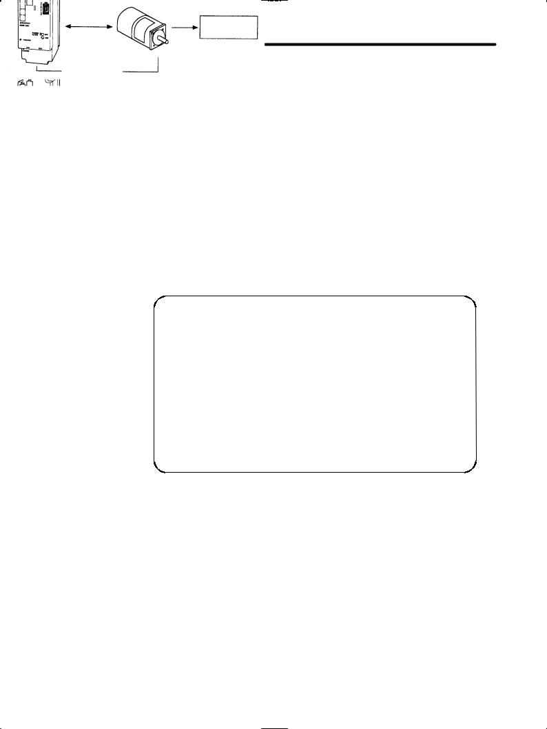
1.3.3How to Use the SGDB SERVOPACKs
1.3.3How to Use the SGDB SERVOPACKs
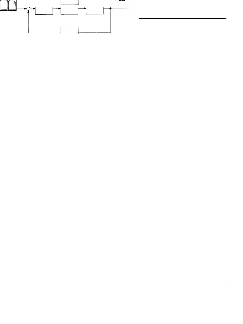
J Using SERVOPACK for Speed Control
The most common use of a SERVOPACK for speed control is shown below:
|
|
|
|
|
|
|
|
|
|
|
|
|
|
Host controller |
||
1 |
|
|
|
|
|
|
|
|
|
|
|
|
|
|
|
|
|
|
|
Position reference + |
|
|
|
|
|
|
|
|
|
||||
|
|
|
|
|
|
|
|
|
|
|
|
|
|
|
Position control loop |
|
|
Position |
|
|
|
|
|
|
|
|
|
|
|
|
|
SERVOPACK |
|
|
|
|
|
|
|
|
|
|
|
|
|
|
|
|||
|
|
|
Speed |
|
|
|
|
|
|
|||||||
|
feedback |
|
|
|
|
|
|
|
||||||||
|
|
reference |
|
|
|
|
|
|
(speed control mode) |
|||||||
|
|
|
|
|
|
|
|
|
|
|
||||||
|
|
|
|
|
|
|
|
|
|
|
|
|
|
|
|
Power |
|
|
|
|
|
|
|
|
|
|
|
|
|
|
amplifier |
||
|
|
|
|
(Analog |
|
|
|
|
|
|
||||||
|
|
|
|
voltage) |
|
|
|
|
|
|
|
|
|
Servomotor |
||
|
|
|
|
|
|
|
|
|
|
|
|
|
|
|
|
|
|
|
|
|
|
|
|
|
|
|
|
|
|
|
|
|
Torque |
|
|
|
|
|
|
|
|
|
|
|
|
|
|
|
|
(current) |
|
|
|
|
|
|
|
Position |
|
|
|
|
|
Speed |
|||
|
|
|
|
|
|
|
|
|
|
|
|
feedback |
||||
|
|
|
|
|
|
|
|
|
|
|
|
|||||
|
|
|
|
|
|
|
|
|
|
|
|
|
|
|
|
|
|
|
|
|
|
|
|
|
Convert |
Pulse train |
|||||||
Position feedback |
Encoder |
|
As shown in the above figure, a position control loop is formed in the host controller. The host controller compares a position reference with a position feedback signal and sends the processed result to the SERVOPACK as a speed reference.
In this way the host controller can be freed from performing the servo mechanism control. The SERVOPACK undertakes the speed control loop and subsequent control processing.
The Yaskawa programmable machine controller MP920 is used as a typical host controller.
12
1.3 Features of Σ -Series Servos
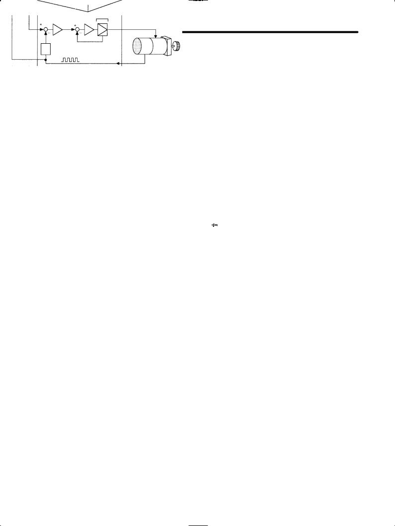
J Using SERVOPACK for Torque Control
SERVOPACK for torque control can be used as shown below:
Host controller
|
|
|
Position |
|
|
||||
|
|
|
monitoring |
|
|
||||
|
|
|
|
1 |
|||||
|
|
|
|
|
|
|
|
|
|
|
|
|
|
|
|
|
|
|
|
Position |
|
SERVOPACK |
|
|
|||||
information |
|
|
|
|
|
||||
|
Torque |
|
(torque control mode) |
||||||
|
|
||||||||
|
|
reference |
|
|
|
|
|
|
|
|
|
|
|
|
Power |
|
|
||
|
|
|
|
|
amplifier |
|
|
||
|
|
|
|
|
|
|
|
Servomotor |
|
(Analog |
|
|
|
|
|
|
|
||
voltage) |
|
|
|
|
|
|
|
||
|
|
Torque |
|
|
|||||
|
|
|
|
|
(current) |
|
|
|
|
|
|
|
|
|
feedback |
|
|
|
|
|
|
|
|
Pulse train |
Encoder |
||||
|
|
|
|
Position feedback |
|
||||
The host controller outputs a torque reference to control the SERVOPACK. It also receives a pulse train (position information) from the SERVOPACK and uses it to monitor the position.
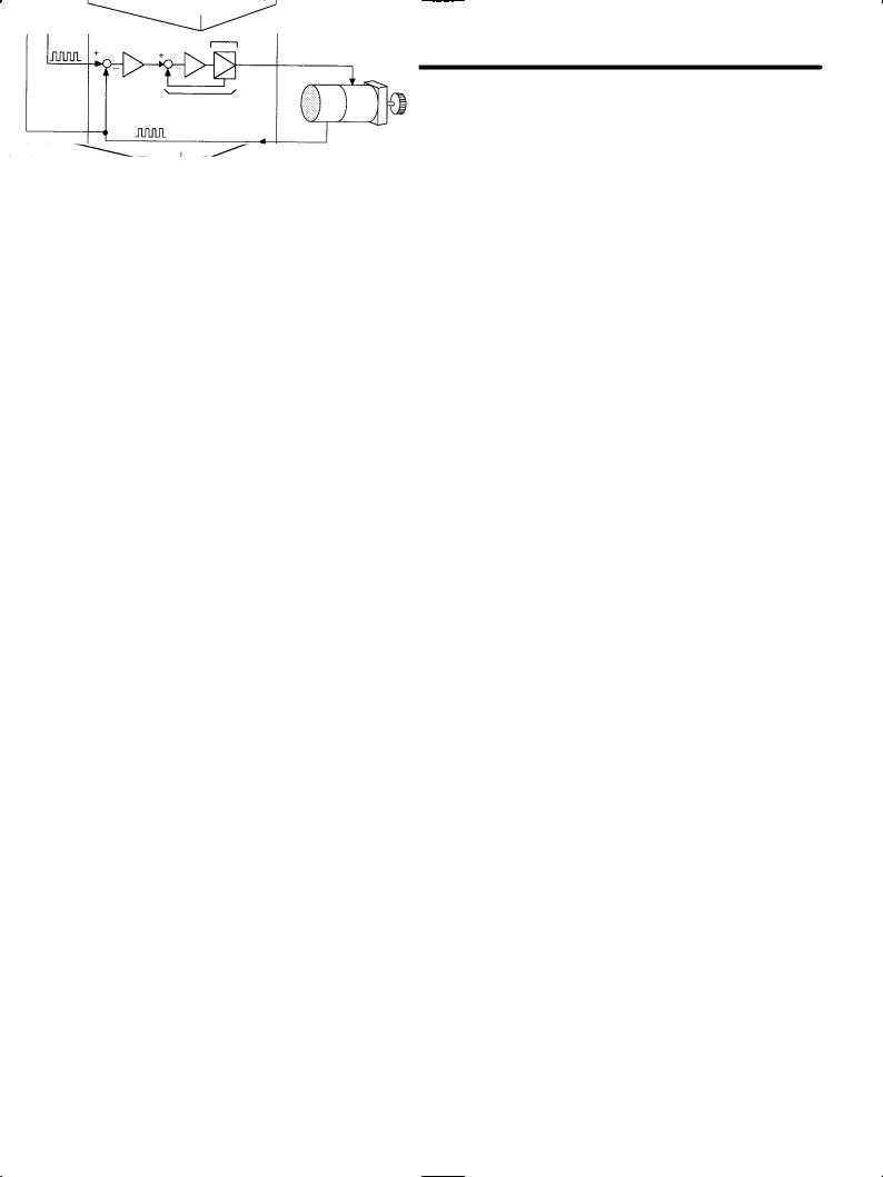
J Using SERVOPACK for Position Control
SERVOPACK for position control can be used as shown below:
Host controller
|
|
|
SERVOPACK |
||
|
Position |
||||
|
reference |
|
(position control mode) |
||
|
|
|
|
|
|
Position |
|
|
|
||
information |
|
|
|
|
|
|
|
Power |
|||
|
|
|
|
amplifier |
|
Servomotor
Pulse train
Speed/current loop |
|
Pulse train |
|
Position feedback |
Encoder |
|
13

FOR FIRST-TIME USERS OF AC SERVOS
1.3.3 |
How to Use the SGDB SERVOPACKs cont. |
|
|
|
The host controller can send a position reference (pulse train) to the SERVOPACK to per- |
|
|
form positioning or interpolation. |
|
|
This type of SERVOPACK contains a position control loop. |
|
|
Parameters can be used to select either of the following pulse trains: |
|
|
(1) Code and pulse train |
|
|
|
1 |
|
(2) Two-phase pulse train with 90° phase difference |
|
|
|
(3) Forward and reverse pulse trains
The host controller receives a pulse train (position information) from the SERVOPACK and uses it to monitor the position.
J Setting Parameters
A Digital Operator can be used to set parameters for a SERVOPACK as follows:
• Setting parameters to enable or disable each function
• Setting parameters required for functions to be used
Set parameters according to the servo system to be set up.
14

BASIC USES OF Σ-SERIES |
2 |
PRODUCTS |
2
This chapter describes the first things to do when Σ-Series products are delivered. It also explains the most fundamental ways of connecting and operating Σ-Series products. Both first-time and experienced servo users must read this chapter.
2.1 |
Precautions . . . . . . . . . . . . . . . . . . . . . . . . . . |
. . . 16 |
|
|
|
2.1.1 |
Notes on Use . . . . . . . . . . . . . . . . . . . . . . . . . . . . . . . |
. . . . . . 16 |
|
2.2 |
Installation . . . . . . . . . . . . . . . . . . . . . . . . . . |
. . . 18 |
|
|
|
2.2.1 |
Checking on Delivery . . . . . . . . . . . . . . . . . . . . . . . . . |
. . . . . . 18 |
|
|
2.2.2 |
Servomotors . . . . . . . . . . . . . . . . . . . . . . . . . . . . . . . . |
. . . . . . 18 |
|
|
2.2.3 |
SERVOPACKs . . . . . . . . . . . . . . . . . . . . . . . . . . . . . . |
. . . . . . 22 |
|
|
2.2.4 |
Installing the Servomotor . . . . . . . . . . . . . . . . . . . . . . |
. . . . . . 24 |
|
|
2.2.5 |
Installing the SERVOPACK . . . . . . . . . . . . . . . . . . . . |
. . . . . . 27 |
|
2.3 |
Connection and Wiring . . . . . . . . . . . . . . . . |
. . . 30 |
|
|
|
2.3.1 Connecting to Peripheral Devices . . . . . . . . . . . . . . . |
. . . . . . 30 |
|
|
|
2.3.2 Main Circuit Wiring and Power ON Sequence . . . . . . |
. . . . . . 34 |
|
|
|
2.3.3 Connection to Host Controller . . . . . . . . . . . . . . . . . . |
. . . . . . 36 |
|
|
2.4 |
Conducting a Test Run . . . . . . . . . . . . . . . . |
. . . 40 |
|
|
|
2.4.1 |
Test Run in Two Steps. . . . . . . . . . . . . . . . . . . . . . . . |
. . . . . . |
40 |
|
2.4.2 |
Step 1: Conducting a Test Run for Motor |
without. . . . Load |
42 |
2.4.3Step 2: Conducting a Test Runthe withMotor Connected to the
|
Machine . . . . . . . . . . . . . . . . . . . . . . . . . . . . . . . . . . . . . . . . . |
46 |
2.4.4 |
Supplementary Information on Test Run . . . . . . . . . . . . . . . . |
47 |
2.4.5 |
Minimum Parameters Required and Input Signals . . . . . . . . . |
49 |
15
BASIC USES OF Σ-SERIES PRODUCTS
2.1.1Notes on Use
2.1 Precautions
This section provides notes on using Σ-Series products.
2.1.1 Notes on Use
NOTE Always note the following to ensure safe use.
2 |
Use 200VAC power supply |
|
|
|
Be sure to use the correct type. Do not plug the |
|
servomotor directly into the power frequency sup- |
|
ply (Direct connection to the power frequency |
|
supply will damage the servomotor.) |
Direct connection
200VAC power supply
Damage will result!
Always use the SGMj servomotor and SGDB SERVOPACK in pairs.
Check whether the combination of applicable motor series of SERVOPACK and of SGMj ( motor series) is correct or not. Check the setting of parameter Cn-2A (motor selection) and always after changing its combination. The motor may get damaged if the combination is not correct.
Do not change wiring when power is ON.
Always turn the power OFF before connecting or disconnecting a connector.
(Except for Digital Operator (Types: JUSP- OP02A-1, JUSP-OP03A))
Recheck the setting of parameter Cn-2A (motor selection) after changing its combination.
Refer to Section 3.3.4.
(POWER and CHARGE lamp)
Always turn the power OFF before connecting or disconnecting a connector.
Note that residual voltage still remains in the SERVOPACK even after the power is turned OFF.
Even after the power is turned OFF, residual elec- |
|
tric charge still remains in the capacitor inside the |
|
SERVOPACK. To prevent an electric shock, al- |
|
ways wait for the CHARGE lamp to go OFF before |
|
starting inspection (if necessary). |
CHARGE lamp |
16

2 . 1 Precautions
Always follow the specified installation method.
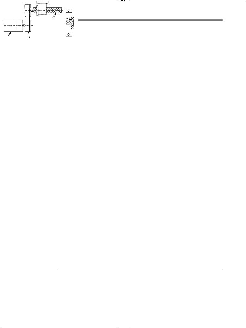
The SERVOPACK generates heat. Install the SERVOPACK so that it can radiate heat freely. Note also that the SERVOPACK must be in an environment free from condensation, vibration and shock.
Perform noise reduction and grounding properly.
Provide sufficient clearance
mm
50 mm or more
Ambient temperature: 0 to 55
If the signal line is noisy, vibration or malfunction will result.
D Separate high-voltage cables from low-voltage cables. D Use cables as short as possible.
D Ground the SERVOPACK ground terminal with the resistance 100Ω or less for the servomotor and SERVOPACK.
D Never use a line filter for the power supply in the motor circuit.
Casing
SERVOPACK
Signal Servomotor line
2
100 Ω or less
Conduct a voltage resistance test under the following conditions.
D Voltage: 1500 Vrms AC, one minute D Current limit: 100 mA
D Frequency: 50/60 Hz
D Voltage application points: Between r, t, R, S, T terminals and frame ground (connect terminals securely).
Use a fast-response type ground-fault interrupter.
Conduct a voltage resistance test under the conditions given on the left.
For a ground-fault interrupter, always use a fastresponse type or one designed for PWM inverters. Do not use a time-delay type.
Ground-fault interrupter
GOOD |
|
GOOD |
|
POOR |
|
|
|
|
|
Fast-response |
|
For PWM |
|
Time-delay |
type |
|
inverter |
|
type |
Do not perform continuous operation under overhanging load.
Continuous operation cannot be performed by rotating the motor from the load and applying regenerative braking. Regenerative braking by the SERVOPACK can be applied only for a short period, such as the motor deceleration time.
Servomotor
Do not apply regenerative braking continuously.
The servomotor cannot be operated by turning the power ON and OFF.
Frequently turning the power ON and OFF causes the internal circuit elements to deteriorate. Always start or stop the servomotor by using reference pulses.
SERVOPACK
Power supply
Do not start or stop by turning power ON and OFF.
17
BASIC USES OF Σ-SERIES PRODUCTS
2.2.2Servomotors
2.2 Installation
This section describes how to check Σ-Series products on delivery and how to install them.
2.2.1 Checking on Delivery
When Σ-Series products are delivered, check the following items:
2 |
|
|
|
|
|
Check Items |
Remarks |
|
|
|
|
|
|
Check if the delivered products are |
Check the types marked on the nameplates of |
|
|
the ones you ordered. |
servomotor and SERVOPACK (see the table below). |
|
|
|
|
|
|
Check if the motor shaft rotates |
If the motor shaft is smoothly turned by hand, it is |
|
|
smoothly. |
normal. However, if the motor has brakes, it cannot be |
|
|
|
turned manually. |
|
|
|
|
|
|
Check for damage. |
Check the overall appearance, and check for damage |
|
|
|
or scratches resulting from transportation. |
|
|
|
|
|
|
Check screws for looseness. |
Check for looseness by using a screwdriver as |
|
|
|
necessary. |
|
|
|
|
If any of the above items are faulty or incorrect, contact the dealer from which you purchased the products or your nearest local sales representative.
2.2.2 Servomotors
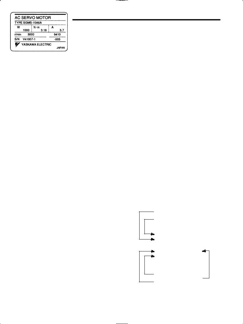
J External Appearance and Nameplate Examples
Rated output
Σ-II Series Servomotor
Rated motor speed
18
Loading...