


VS-616PC5/P5 Series
User’s Manual
Variable Torque Inverter
(with software version 5110/5120 and newer)

! WARNING
PRECAUTIONS
1)Read this manual in its entirety before installing or operating the VS616PC5/P5 inverter. This manual applies to inverters with software versions 5110 and 5120 only and is not intended to be used in conjunction with any other software.
2)Do not connect or disconnect wiring, or perform signal checks while the power supply is turned ON.
3)The VS-616PC5/P5 internal capacitor may be charged even after the power supply is turned OFF. To prevent electrical shock, disconnect all power before servicing the inverter. Then wait at least five minutes after the power supply is disconnected and all LEDs are extinguished.
4)Do not perform a withstand voltage test or a megger test on any part of the VS-616PC5/P5. This electronic equipment uses semiconductors and is vulnerable to high voltage.
5)Do not remove the operator unless the power supply is turned OFF. Never touch the printed control board while the power supply is turned ON.
6)The VS-616PC5/P5 is suitable for use on a circuit capable of delivering not more than 65,000 RMS symmetrical amperes, 480 Volts maximum (460V class units), 240 Volts maximum (230V class units).
Failure to observe these and other precautions highlighted in this manual will expose the user to high voltages, resulting in equipment damage, serious injury or death.
NOTICE
Printed April, 1999. The information contained within this document is the proprietary property of Yaskawa Electric America, Inc., and may not be copied, reproduced or transmitted to other parties without the expressed written authorization of Yaskawa Electric America, Inc.
No patent liability is assumed with respect to the use of the information contained herein. Moreover, because Yaskawa is constantly improving its high-quality products, the information contained in this manual is subject to change without notice. Every precaution has been taken in the preparation of this manual. Nevertheless, Yaskawa assumes no responsibility for errors or omissions. Neither is any liability assumed for damages resulting from the use of the information contained in this publication.
2 |
VS-616PC5/P5 User’s Manual |

|
|
Contents |
CONTENTS |
|
|
Section |
Description |
Page |
1 |
RECEIVING & INSTALLATION |
|
1.1 |
INTRODUCTION . . . . . . . . . . . . . . . . . . . . . . . . . . . . |
. . . . . . . 6 |
1.2 |
SPECIFICATIONS . . . . . . . . . . . . . . . . . . . . . . . . . . . . . |
. . . . . . 7 |
|
VS-616PC5 . . . . . . . . . . . . . . . . . . . . . . . . . . . . . . |
. . . . . . 7 |
|
VS-616P5. . . . . . . . . . . . . . . . . . . . . . . . . . . . . . . . |
. . . . . . 9 |
1.3 |
PRELIMINARY INSPECTION . . . . . . . . . . . . . . . . . . . . |
. . . . . 11 |
|
Receiving . . . . . . . . . . . . . . . . . . . . . . . . . . . . . . . . |
. . . . . 11 |
|
Checking the Nameplate . . . . . . . . . . . . . . . . . . . . |
. . . . . 11 |
|
Identifying the Parts. . . . . . . . . . . . . . . . . . . . . . . . |
. . . . . 12 |
1.4 |
MOUNTING. . . . . . . . . . . . . . . . . . . . . . . . . . . . . . . . . |
. . . . . 13 |
|
Precautions. . . . . . . . . . . . . . . . . . . . . . . . . . . . . . . |
. . . . . 13 |
|
Choosing a Location . . . . . . . . . . . . . . . . . . . . . . . |
. . . . . 13 |
|
Removing and Replacing the Digital Operator . . |
. . . . . 14 |
|
Removing and Replacing the Front Cover. . . . . . |
. . . . . 14 |
|
Dimensions/Heat Loss. . . . . . . . . . . . . . . . . . . . . . |
. . . . . 15 |
|
Clearances . . . . . . . . . . . . . . . . . . . . . . . . . . . . . . . |
. . . . . 17 |
1.5 |
WIRING. . . . . . . . . . . . . . . . . . . . . . . . . . . . . . . . . . . . |
. . . . . 18 |
|
Precautions. . . . . . . . . . . . . . . . . . . . . . . . . . . . . . . |
. . . . . 18 |
|
Inspection . . . . . . . . . . . . . . . . . . . . . . . . . . . . . . . . |
. . . . . 18 |
|
VS-616PC5 Connection Diagram . . . . . . . . . . . . |
. . . . . 19 |
|
VS-616P5 Connection Diagram . . . . . . . . . . . . . . |
. . . . . 20 |
|
Main Circuit Wiring . . . . . . . . . . . . . . . . . . . . . . . |
. . . . . 21 |
|
Terminal Functions . . . . . . . . . . . . . . . . . . . . . . . . |
. . . . . 24 |
|
Wire and Terminal Screw Sizes . . . . . . . . . . . . . . |
. . . . . 25 |
|
Control Circuit Wiring. . . . . . . . . . . . . . . . . . . . . . |
. . . . . 28 |
2 |
OPERATION |
|
Precautions. . . . . . . . . . . . . . . . . . . . . . . . . . . . . . . . . . . . 30
2.1 |
TRIAL OPERATION . . . . . . . . . . . . . . . . . . . . . . . . . . . . . . . . |
31 |
|
Display at Power-up . . . . . . . . . . . . . . . . . . . . . . . . . . . . |
31 |
|
Operation Checkpoints . . . . . . . . . . . . . . . . . . . . . . . . . . |
32 |
|
Basic Operation . . . . . . . . . . . . . . . . . . . . . . . . . . . . . . . . |
32 |
2.2 |
DIGITAL OPERATOR DISPLAY. . . . . . . . . . . . . . . . . . . . . . . |
35 |
2.3 |
LED DESCRIPTION . . . . . . . . . . . . . . . . . . . . . . . . . . . . . . . |
36 |
2.4 |
OPERATION MODE SELECTION . . . . . . . . . . . . . . . . . . . . . . |
37 |
3 |
PROGRAMMING FEATURES |
|
3.1 |
VS-616PC5/P5 PARAMETERS (n001~n116) . . . . . . . . . . . |
41 |
3.2 |
PARAMETER SET-UP & INITIALIZATION. . . . . . . . . . . . . . . |
49 |
3.3 |
VS-616PC5/P5 OPERATION . . . . . . . . . . . . . . . . . . . . . . . . |
50 |
|
Accel/decel time adjustment . . . . . . . . . . . . . . . . . . . . . . |
50 |
|
Automatic fault retry . . . . . . . . . . . . . . . . . . . . . . . . . . . . |
51 |
|
Automatic restart after momentary power loss . . . . . . . |
51 |
|
Carrier frequency. . . . . . . . . . . . . . . . . . . . . . . . . . . . . . . |
51 |
VS-616PC5/P5 User’s Manual |
3 |

Contents
Current limit (Stall prevention). . . . . . . . . . . . . . . . . . . . 52 DC injection braking . . . . . . . . . . . . . . . . . . . . . . . . . . . . 54 Energy savings control . . . . . . . . . . . . . . . . . . . . . . . . . . 55 Frequency agree set point . . . . . . . . . . . . . . . . . . . . . . . . 57 Frequency meter or ammeter . . . . . . . . . . . . . . . . . . . . . 58 Frequency meter or ammeter calibration . . . . . . . . . . . . 58 Frequency signal adjustment. . . . . . . . . . . . . . . . . . . . . . 58 Jog operation . . . . . . . . . . . . . . . . . . . . . . . . . . . . . . . . . . 60 Jump frequencies . . . . . . . . . . . . . . . . . . . . . . . . . . . . . . . 60 MODBUS communication . . . . . . . . . . . . . . . . . . . . . . . 61 Motor overload detection . . . . . . . . . . . . . . . . . . . . . . . . 62 Multi-step speed selection. . . . . . . . . . . . . . . . . . . . . . . . 64 Phase loss detection. . . . . . . . . . . . . . . . . . . . . . . . . . . . . 65 PID Control . . . . . . . . . . . . . . . . . . . . . . . . . . . . . . . . . . . 66 Reverse run prohibit . . . . . . . . . . . . . . . . . . . . . . . . . . . . 68 Soft-start characteristics . . . . . . . . . . . . . . . . . . . . . . . . . 68 Speed limit adjustment . . . . . . . . . . . . . . . . . . . . . . . . . . 69 Stopping method . . . . . . . . . . . . . . . . . . . . . . . . . . . . . . . 70 Torque adjustment . . . . . . . . . . . . . . . . . . . . . . . . . . . . . . 72 Torque detection . . . . . . . . . . . . . . . . . . . . . . . . . . . . . . . 73 Tripless operation . . . . . . . . . . . . . . . . . . . . . . . . . . . . . . 74 V/f pattern adjustment . . . . . . . . . . . . . . . . . . . . . . . . . . . 75 Slip compensation . . . . . . . . . . . . . . . . . . . . . . . . . . . . . . 77
3.4 |
INPUTS & OUTPUTS. . . . . . . . . . . . . . . . . . . . . . . . . . . . . . . |
78 |
|
Multi-function input signals . . . . . . . . . . . . . . . . . . . . . . |
78 |
|
Analog input signals . . . . . . . . . . . . . . . . . . . . . . . . . . . . |
82 |
|
Multi-function output signals . . . . . . . . . . . . . . . . . . . . . |
83 |
4 |
DIAGNOSTICS |
|
|
Precautions. . . . . . . . . . . . . . . . . . . . . . . . . . . . . . . . . . . . |
86 |
4.1 |
MAINTENANCE & INSPECTION . . . . . . . . . . . . . . . . . . . . . . |
87 |
|
Periodic Inspection . . . . . . . . . . . . . . . . . . . . . . . . . . . . . |
87 |
|
Parts Replacement Schedule . . . . . . . . . . . . . . . . . . . . . . |
87 |
4.2 |
ALARM & FAULT DISPLAY. . . . . . . . . . . . . . . . . . . . . . . . . |
88 |
|
Alarm Display . . . . . . . . . . . . . . . . . . . . . . . . . . . . . . . . . |
88 |
|
Fault Display . . . . . . . . . . . . . . . . . . . . . . . . . . . . . . . . . . |
89 |
|
Motor Faults. . . . . . . . . . . . . . . . . . . . . . . . . . . . . . . . . . . |
92 |
A |
APPENDIX |
|
A-1 |
BRAKING CONNECTION DIAGRAMS . . . . . . . . . . . . . . . . . . |
94 |
A-2 |
DIGITAL OPERATOR MONITOR DISPLAY . . . . . . . . . . . . . . |
95 |
A-3 |
CE CONFORMANCE . . . . . . . . . . . . . . . . . . . . . . . . . . . . . . . |
97 |
4 |
VS-616PC5/P5 User’s Manual |

Chapter 1 - Receiving & Installation
- CHAPTER 1 -
RECEIVING & INSTALLATION
Section |
Description |
Page |
1 |
RECEIVING & INSTALLATION |
|
1.1 |
INTRODUCTION . . . . . . . . . . . . . . . . . . . . . . . . . . . . . . . . |
. . . 6 |
1.2 |
SPECIFICATIONS . . . . . . . . . . . . . . . . . . . . . . . . . . . . . . . . |
. . . 7 |
|
VS-616PC5 . . . . . . . . . . . . . . . . . . . . . . . . . . . . . . . . . |
. . . 7 |
|
VS-616P5. . . . . . . . . . . . . . . . . . . . . . . . . . . . . . . . . . . |
. . . 9 |
1.3 |
PRELIMINARY INSPECTION . . . . . . . . . . . . . . . . . . . . . . . |
. . 11 |
|
Receiving . . . . . . . . . . . . . . . . . . . . . . . . . . . . . . . . . . . |
. . 11 |
|
Checking the Nameplate . . . . . . . . . . . . . . . . . . . . . . . |
. . 11 |
|
Identifying the Parts. . . . . . . . . . . . . . . . . . . . . . . . . . . |
. . 12 |
1.4 |
MOUNTING. . . . . . . . . . . . . . . . . . . . . . . . . . . . . . . . . . . . |
. . 13 |
|
Precautions. . . . . . . . . . . . . . . . . . . . . . . . . . . . . . . . . . |
. . 13 |
|
Choosing a Location . . . . . . . . . . . . . . . . . . . . . . . . . . |
. . 13 |
|
Removing and Replacing the Digital Operator . . . . . |
. . 14 |
|
Removing and Replacing the Front Cover. . . . . . . . . |
. . 14 |
|
Dimensions/Heat Loss. . . . . . . . . . . . . . . . . . . . . . . . . |
. . 15 |
|
Clearances . . . . . . . . . . . . . . . . . . . . . . . . . . . . . . . . . . |
. . 17 |
1.5 |
WIRING. . . . . . . . . . . . . . . . . . . . . . . . . . . . . . . . . . . . . . . |
. . 18 |
|
Precautions. . . . . . . . . . . . . . . . . . . . . . . . . . . . . . . . . . . |
. 18 |
|
Inspection . . . . . . . . . . . . . . . . . . . . . . . . . . . . . . . . . . . . |
. 18 |
|
VS-616PC5 Connection Diagram . . . . . . . . . . . . . . . . |
. 19 |
|
VS-616P5 Connection Diagram . . . . . . . . . . . . . . . . . . |
. 20 |
|
Main Circuit Wiring . . . . . . . . . . . . . . . . . . . . . . . . . . . |
. 21 |
|
Terminal Functions . . . . . . . . . . . . . . . . . . . . . . . . . . . . |
. 24 |
|
Wire and Terminal Screw Sizes . . . . . . . . . . . . . . . . . . |
. 25 |
|
Control Circuit Wiring. . . . . . . . . . . . . . . . . . . . . . . . . . |
. 28 |
VS-616PC5/P5 User’s Manual |
5 |

Chapter 1 - Receiving & Installation
Introduction
1.1 INTRODUCTION
The VS-616PC5/P5 is a series of high quality, variable torque inverters. With a power range of 5 to 500 HP, it provides all the functionality of prior series, in a compact, low cost package. This functionality includes Yaskawa proprietary features like full-range automatic torque boost, electronic thermal motor overload, energy savings and PID operation, lownoise operation and various other features. It also features a new digital operator for simple programming. Utilizing the latest microprocessor technology, members of Yaskawa’s design team have collaborated to make the VS-616PC5/P5 the world’s first optimized inverter specifically designed for variable torque applications.
This manual details installation, start-up and operating procedures for the VS-616PC5/P5 series adjustable frequency drive controller. Descriptions of diagnostic and troubleshooting procedures are also included herein.
6 |
VS-616PC5/P5 User’s Manual |

Chapter 1 - Receiving & Installation
Specifications
1.2 SPECIFICATIONS
VS-616PC5
|
Inverter Model |
|
|
|
|
VS-616PC5 |
|
|
|
|
||
|
CIMR-P5U |
20P4 |
20P7 |
21P5 |
22P2 |
23P7 |
25P5 |
27P5 |
2011 |
2015 |
- |
|
|
Motor Output (HP) * |
0.5 |
1 |
2 |
3 |
5 |
7.5 |
10 |
20 |
25 |
- |
|
|
Capacity (kVA) |
1.2 |
2.3 |
3.0 |
4.2 |
6.7 |
9.5 |
13 |
19 |
24 |
- |
|
Characteristics |
Rated Output |
3.2 |
6 |
8 |
11 |
17.5 |
27 |
36 |
54 |
68 |
- |
|
Current (A)-VT** |
||||||||||||
|
|
|
|
|
|
|
|
|
|
|||
Rated Output |
3.2 |
6 |
8 |
11 |
17.5 |
25 |
33 |
49 |
64 |
- |
||
Current (A)-CT** |
||||||||||||
|
|
|
|
|
|
|
|
|
|
|||
Max. Voltage |
|
|
|
3-Phase, 200/208/220/230V |
|
|
|
|||||
Output |
|
|
|
|
|
|
||||||
|
|
|
(Proportional to input voltage) |
|
|
|
||||||
|
|
|
|
|
|
|
||||||
Rated Output Frequency |
|
|
|
|
0.1 to 400 Hz |
|
|
|
|
|||
|
|
|
|
|
|
|
|
|
||||
|
|
|
|
|
|
|
||||||
|
Overload Capacity - VT |
|
|
120% Rated Output Current for 1 minute |
|
|
||||||
|
Overload Capacity - CT |
|
|
150% Rated Output Current for 1 minute |
|
|
||||||
Supply |
Input Current (A) |
3.9 |
7.2 |
9.6 |
13.2 |
21 |
33 |
44 |
65 |
82 |
- |
|
Rated Voltage & |
|
|
|
|
3-Phase |
|
|
|
|
|||
Frequency |
|
|
|
220 - 230V, 50/60Hz |
|
|
|
|||||
Power |
|
|
|
|
|
|
||||||
|
|
|
|
|
|
|
|
|
|
|||
Voltage Fluctuation |
|
|
|
|
+10%, -15% |
|
|
|
|
|||
Frequency Fluctuation |
|
|
|
|
±5% |
|
|
|
|
|||
|
|
|
|
|
|
|
|
|
||||
|
CIMR-P5U |
40P4 |
40P7 |
41P5 |
42P2 |
43P7 |
44P0 |
45P5 |
47P5 |
4011 |
4015 |
|
|
Motor Output (HP) * |
0.5 |
1 |
2 |
3 |
5 |
7.5 |
10 |
15 |
20 |
25 |
|
|
Capacity (kVA) |
1.4 |
2.6 |
3.7 |
4.7 |
6.1 |
8.6 |
11 |
14 |
21 |
26 |
|
Characteristics |
Rated Output |
1.9 |
3.6 |
5.1 |
6.6 |
8.5 |
11.7 |
14.8 |
21.0 |
28.6 |
34.0 |
|
Current (A)-VT** |
||||||||||||
|
|
|
|
|
|
|
|
|
|
|||
Rated Output |
1.9 |
3.6 |
5.1 |
6.6 |
8.5 |
11.7 |
14.8 |
18 |
28.6 |
34.0 |
||
Current (A)-CT** |
||||||||||||
|
|
|
|
|
|
|
|
|
|
|||
Max. Voltage # |
|
|
3-Phase, 380/400/415/440/460V |
|
|
|||||||
|
|
|
|
|
|
|
|
|
|
|||
Output |
|
|
|
(Proportional to input voltage) |
|
|
|
|||||
|
|
|
|
|
|
|
||||||
Rated Output Frequency |
|
|
|
|
0.1 to 400 Hz |
|
|
|
|
|||
|
Overload Capacity-VT** |
|
|
120% Rated Output Current for 1 minute |
|
|
||||||
|
|
|
(Model 47P5 is rated 150% / 1 minute) |
|
|
|||||||
|
|
|
|
|
|
|||||||
|
|
|
|
|
|
|
||||||
|
Overload Capacity-CT** |
|
|
150% Rated Output Current for 1 minute |
|
|
||||||
Supply |
Input Current (A) |
2.3 |
4.3 |
6.1 |
8.0 |
10.2 |
14.0 |
17.8 |
26.0 |
35.0 |
40.0 |
|
Rated Voltage & |
|
|
|
|
3-Phase |
|
|
|
|
|||
Frequency # |
|
|
|
380 -440 - 460V, 50/60Hz |
|
|
|
|||||
Power |
|
|
|
|
|
|
|
|
|
|
||
Voltage Fluctuation |
|
|
|
|
+10%, -15% |
|
|
|
|
|||
|
|
|
|
|
|
|
|
|
|
|
||
Frequency Fluctuation |
|
|
|
|
±5% |
|
|
|
|
|||
|
|
|
|
|
|
|
|
|
||||
* HP ratings based on standard NEMA 4-pole motor data.
# For 380V operation, the motor rated current must be less than or equal to the inverter rated current.
** VT: Variable Torque rating (n116=1), CT: Constant Torque rating (n116=0) Note: Shaded areas indicate factory settings.
VS-616PC5/P5 User’s Manual |
7 |

Chapter 1 - Receiving & Installation
Specifications
|
Control Method |
Sine wave PWM with full-range, automatic torque boost |
|
|
Frequency Control |
0.1 to 400 Hz |
|
|
Range |
||
|
|
||
|
|
|
|
Characteristics |
Frequency Accuracy |
Digital command: 0.01%, Analog command: 0.1% |
|
Frequency Setting Reso- |
0.01 Hz |
||
|
Digital Operator Reference: 0.1Hz, |
||
|
lution |
Analog Reference: 0.06Hz (@60Hz) |
|
|
Output Frequency Reso- |
|
|
Control |
lution |
|
|
Frequency Setting |
0 to +10VDC (20kΩ), 4-20mA (250Ω) |
||
|
|||
|
|
|
|
|
Accel/Decel Time |
0.0 to 3600.0 sec. |
|
|
(Accel/Decel time setting independently: 0.1 sec ) |
||
|
|
||
|
Braking Torque |
Approx. 20% |
|
|
|
|
|
|
No. of V-f Patterns |
1 preset V/f pattern and 1 custom pattern |
|
|
Motor Overload Protec- |
Electronic thermal overload relay (I2T) |
|
|
tion |
||
|
|
||
|
Instantaneous Overcur- |
Motor coasts to stop at approx. 200% rated output current. |
|
|
rent |
||
|
|
||
|
|
|
|
|
Fuse Protection |
Motor coasts to stop at blown fuse. |
|
|
Overload |
Motor coasts to stop after 1 min. at rated overload capacity. |
|
|
|
|
|
Functions |
Overvoltage |
Motor coasts to a stop if converter output voltage exceeds 410VDC |
|
Motor coasts to stop if converter output voltage drops below user |
|||
|
|
(820VDC at 460V input) |
|
Protective |
Undervoltage |
tion during power loss less than 2 sec is equipped as standard.) |
|
Momentary Power Loss |
|||
|
|
adjustable value |
|
|
|
Immediate stop after 15 ms or longer power loss. (Continuous system opera- |
|
|
|
|
|
|
Heatsink Overheat |
Thermistor - OH1, OH2 |
|
|
|
|
|
|
Stall Prevention |
Stall prevention at acceleration/deceleration and constant speed |
|
|
operation |
||
|
|
||
|
Ground Fault |
Provided by electronic circuit |
|
|
|
|
|
|
Power Charge Indication |
Charge LED stays on until voltage drops below 50VDC |
|
|
Input Phase Loss |
Single-phase protection |
|
Conditions |
Location |
Indoor (protected from corrosive gases and dust) |
|
|
|||
|
Ambient |
+14 to 104°F (-10 to 40°C) for NEMA 1 type (not frozen) |
|
|
Temperature |
+14 to 113°F (-10 to 45°C) for open chassis type |
|
Environmental |
Storage |
9.8m/s2 (1G) less than 20Hz, up to 1.96m/s2 (0.2G) at 20 to 50Hz |
|
Vibration |
|||
|
Temperature |
-4 to 140°F (-20 to 60°C) |
|
|
Humidity |
95% RH (non-condensing) |
|
|
|
|
8 |
VS-616PC5/P5 User’s Manual |

Chapter 1 - Receiving & Installation
Specifications
VS-616P5
|
Inverter Model |
|
|
|
|
|
|
VS-616P5 |
|
|
|
|
|
|
|
|
|
CIMR-P5U |
|
|
|
|
|
|
|
|
|
|
|
|
|
|
|
|
2018 |
2022 |
2030 |
2037 |
2045 |
2055 |
2075 |
|
|
|
|
|
|
|
||
|
|
|
|
|
|
|
|
|
|
|
|
|
|
|
|
|
|
Motor Output (HP) * |
30 |
40 |
50 |
60 |
75 |
|
100 |
125 |
|
|
|
|
|
|
|
|
|
|
|
|
|
|
|
|
|
|
|
|
|
|
|
|
|
Capacity (kVA) |
30 |
37 |
50 |
61 |
70 |
|
85 |
110 |
|
|
|
|
|
|
|
|
|
|
|
|
|
|
|
|
|
|
|
|
|
— |
|
|
Characteristics |
Rated Output |
80 |
104 |
130 |
160 |
192 |
|
248 |
312 |
|
|
|
|
|
|
|
Current (A) - VT ** |
|
|
|
|
|
|
|
|
||||||||
|
|
|
|
|
|
|
|
|
|
|
|
|
|
|
||
Rated Output |
64 |
83 |
104 |
128 |
154 |
|
198 |
250 |
|
|
|
|
|
|
|
|
Current (A) - CT ** |
|
|
|
|
|
|
|
|
||||||||
|
|
|
|
|
|
|
|
|
|
|
|
|
|
|
||
|
|
|
|
|
|
|
|
|
|
|
|
|
|
|
|
|
|
|
|
|
3-Phase, 200/208/220/230V |
|
|
|
|||||||||
Output |
Max. Voltage |
|
|
|
|
|
|
|||||||||
|
|
|
(Proportional to input voltage) |
|
|
|
||||||||||
|
|
|
|
|
|
|
||||||||||
|
|
|
|
|
|
|
|
|
|
|
|
|
|
|
|
|
Rated Output Frequency |
|
|
|
|
|
0.1 to 400 Hz |
|
|
|
|
|
|
|
|||
|
|
|
|
|
|
|
|
|
|
|
|
|
||||
|
|
|
|
|
|
|
|
|||||||||
|
Overload Capacity - VT ** |
|
|
120% Rated Output Current / 1 minute |
|
|
|
|||||||||
|
|
|
|
|
|
|
|
|||||||||
|
Overload Capacity - CT ** |
|
|
150% Rated Output Current / 1 minute |
|
|
|
|||||||||
|
|
|
|
|
|
|
|
|
|
|
|
|
|
|
|
|
Supply |
Input Current (A) |
88 |
119 |
143 |
176 |
212 |
|
270 |
344 |
|
|
|
|
— |
|
|
|
|
|
|
|
|
|
|
|
|
|
|
|
|
|
|
|
Rated Voltage & |
|
|
|
|
|
|
3-Phase |
|
|
|
|
|
|
|
||
Frequency |
|
|
|
|
220 - 230V, 50/60Hz |
|
|
|
|
|
||||||
Power |
|
|
|
|
|
|
|
|
|
|||||||
|
|
|
|
|
|
|
|
|
|
|
|
|
|
|||
Voltage Fluctuation |
|
|
|
|
|
+10%, -15% |
|
|
|
|
|
|
|
|||
|
|
|
|
|
|
|
|
|
|
|
|
|
|
|
|
|
Frequency Fluctuation |
|
|
|
|
|
±5% |
|
|
|
|
|
|
|
|||
|
|
|
|
|
|
|
|
|
|
|
|
|
||||
|
|
|
|
|
|
|
|
|
|
|
|
|
|
|||
|
CIMR-P5U |
4018 |
4022 |
4030 |
4037 |
4045 |
4055 |
4075 |
4110 |
4160 |
4185 |
4220 |
4300 |
|||
|
|
|
|
|
|
|
|
|
|
|
|
|
|
|
|
|
|
Motor Output (HP) * |
30 |
40 |
50 |
60 |
75 |
|
100 |
150 |
200 |
|
250 |
|
300 |
400 |
500 |
|
|
|
|
|
|
|
|
|
|
|
|
|
|
|
|
|
|
Capacity (kVA) |
31 |
40 |
50 |
61 |
73 |
|
98 |
130 |
170 |
|
230 |
|
260 |
340 |
460 |
|
|
|
|
|
|
|
|
|
|
|
|
|
|
|
|
|
Characteristics |
Rated Output |
41 |
52 |
65 |
80 |
96 |
|
128 |
180 |
240 |
|
302 |
|
380 |
506 |
675 |
Current (A) - VT ** |
|
|
|
|||||||||||||
|
|
|
|
|
|
|
|
|
|
|
|
|
|
|
||
Rated Output |
32 |
42 |
52 |
64 |
77 |
|
102 |
144 |
182 |
|
242 |
|
304 |
404 |
540 |
|
Current (A) - CT ** |
|
|
|
|||||||||||||
|
|
|
|
|
|
|
|
|
|
|
|
|
|
|
||
|
|
|
|
|
|
|
|
|
|
|
|
|
|
|
|
|
|
|
|
|
3-Phase, 380/400/415/440/460V |
|
|
|
|||||||||
Output |
Max. Voltage # |
|
|
|
|
|
|
|||||||||
|
|
|
(Proportional to input voltage) |
|
|
|
||||||||||
|
|
|
|
|
|
|
||||||||||
|
|
|
|
|
|
|
|
|
|
|
|
|
|
|
|
|
Rated Output Frequency |
|
|
|
|
|
0.1 to 400 Hz |
|
|
|
|
|
|
|
|||
|
|
|
|
|
|
|
|
|
|
|
|
|
||||
|
|
|
|
|
|
|
|
|
||||||||
|
Overload Capacity - VT ** |
|
|
|
120% Rated Current / 1 minute |
|
|
|
||||||||
|
|
|
|
|
|
|
|
|
||||||||
|
Overload Capacity - CT ** |
|
|
|
150% Rated Current / 1 minute |
|
|
|
||||||||
|
|
|
|
|
|
|
|
|
|
|
|
|
|
|
|
|
Supply |
Input Current (A) |
46 |
58 |
72 |
88 |
106 |
|
141 |
198 |
264 |
|
330 |
|
456 |
608 |
810 |
|
|
|
|
|
|
|
|
|
|
|
|
|
|
|
|
|
Rated Voltage & |
|
|
|
|
|
|
3-Phase |
|
|
|
|
|
|
|
||
Frequency # |
|
|
|
|
380 -440 - 460V, 50/60Hz |
|
|
|
|
|
||||||
Power |
|
|
|
|
|
|
|
|
|
|
|
|
|
|
||
Voltage Fluctuation |
|
|
|
|
|
+10%, -15% |
|
|
|
|
|
|
|
|||
|
|
|
|
|
|
|
|
|
|
|
|
|
|
|
|
|
|
Frequency Fluctuation |
|
|
|
|
|
±5% |
|
|
|
|
|
|
|
||
|
|
|
|
|
|
|
|
|
|
|
|
|
|
|
|
|
* HP ratings based on standard NEMA 4-pole motor data.
# For 380V operation, the motor rated current must be less than or equal to the inverter rated current.
** VT: Variable Torque rating (n116=1), CT: Constant Torque rating (n116=0) Note: Shaded areas indicate factory settings.
VS-616PC5/P5 User’s Manual |
9 |

Chapter 1 - Receiving & Installation
Specifications
|
Control Method |
Sine wave PWM with full-range, automatic torque boost |
|
|
|
|
|
|
Frequency Control Range |
0.1 to 400 Hz |
|
|
|
|
|
|
Frequency Accuracy |
Digital command: 0.01%, Analog command: 0.1% |
|
Characteristics |
|
|
|
Frequency Setting |
Digital Operator Reference: 0.1Hz, |
||
|
|||
|
Resolution |
Analog Reference: 0.06Hz (@60Hz) |
|
|
|
|
|
|
Output Frequency |
0.01 Hz |
|
|
Resolution |
||
|
|
||
Control |
|
|
|
Frequency Setting |
0.0 to 3600.0 sec. |
||
|
0 to +10VDC (20kΩ), 4-20mA (250Ω) |
||
|
Accel/Decel Time |
(Accel/Decel time setting independently: 0.1 sec ) |
|
|
|
||
|
|
|
|
|
Braking Torque |
Approx. 20% |
|
|
|
|
|
|
No. of V-f Patterns |
1 preset V/f pattern and 1 custom pattern |
|
|
|
|
|
|
Motor Overload Protection |
Electronic thermal overload relay (I2T) |
|
|
Instantaneous Overcurrent |
Motor coasts to stop at approx. 180% rated output current. |
|
|
|
|
|
|
Fuse Protection |
Motor coasts to stop at blown fuse. |
|
|
|
|
|
|
Overload |
Motor coasts to stop after 1 min. at rated overload capacity. |
|
|
|
|
|
Functions |
Overvoltage |
Motor coasts to stop if converter output voltage exceeds 410VDC |
|
(820VDC at 460V input) |
|||
Undervoltage |
|||
|
|
||
|
|
|
|
|
|
Motor coasts to stop if converter output voltage drops below user |
|
Protective |
|
adjustable value |
|
|
|
||
Momentary Power Loss |
Immediately stop after 15 ms or longer power loss. (Continuous system |
||
|
|||
|
operation during power loss less than 2 sec is equipped as standard.) |
||
|
|
||
|
|
|
|
|
Heatsink Overheat |
Thermistor - OH1, OH2 |
|
|
|
|
|
|
Stall Prevention |
Stall prevention at acceleration/deceleration and constant speed operation |
|
|
|
|
|
|
Ground Fault |
Provided by electronic circuit |
|
|
|
|
|
|
Power Charge Indication |
Charge LED stays on until voltage drops below 50VDC |
|
|
|
|
|
|
Input Phase Loss |
Single-phase protection |
|
|
|
|
|
Conditions |
Location |
Indoor (protected from corrosive gases and dust) |
|
|
|
||
|
+14 to 113°F (-10 to 45°C) for open chassis type |
||
|
Ambient Temperature |
+14 to 104°F (-10 to 40°C) for NEMA 1 type (not frozen) |
|
|
|
||
Environmental |
|
|
|
Vibration |
9.8m/s2 (1G) less than 20Hz, up to 1.96m/s2 (0.2G) at 20 to 50Hz |
||
|
Storage Temperature |
-4 to 140°F (-20 to 60°C) |
|
|
Humidity |
95% RH (non-condensing) |
|
|
|
|
10 |
VS-616PC5/P5 User’s Manual |
Chapter 1 - Receiving & Installation
Preliminary Inspection
1.3 PRELIMINARY INSPECTION
Receiving
After unpacking the VS-616PC5/P5:
·Verify that the part numbers on the drive nameplate match the numbers on your purchase order or packing slip.
·Check the unit for physical damage which may have occurred during shipping. If any part of the drive is missing or damaged, notify the carrier and your Yaskawa representative immediately.
·Verify that all internal hardware (i.e. components, screws, etc.) is seated properly and fastened securely.
·Verify that the instruction manual is included (YEA-TOA-S616-12).
·If the drive will be stored after receiving, place it in its original packaging and store according to temperature specifications on page 8.
Checking the Nameplate
Inverter |
|
|
MODEL : CIMR-P5U43P7 SPEC : 43P71F_ |
|
|
|
Inverter |
|||
|
|
|
||||||||
Model |
|
|
|
|
|
|
Spec. |
|||
INPUT : AC 3PH 380-440V 50Hz |
10.2A |
|||||||||
Input Spec. |
|
|
|
|
|
|
||||
|
|
|
|
|
||||||
|
|
|
380-460V 60Hz |
|
|
|
|
|
|
|
Output Spec. |
|
|
OUTPUT : AC 3PH 0-460V 6.1kVA |
8.5A |
|
|
|
|
||
|
|
|
|
|
||||||
Lot No. |
|
|
LOT NO : |
MASS : 4.5 kg |
|
|
|
Mass |
||
|
|
|
||||||||
Serial No. |
|
|
SER NO : |
|
Mg |
|
|
|
|
|
|
|
|
|
|
|
|||||
UL File No. |
|
|
UL FILE NO : E131457 |
|
|
|
|
|
||
|
|
|
|
|
|
|
|
|||
Figure 1 Nameplate Example of American Model CIMR-P5U43P7
CIMR - P5 U 4 3P7 1 F
Inverter 
VS-616PC5/P5 Series
Specifications
A:Japanese specifications
E:European specifications
U:American specifications
Voltage Class
2:3-phase, 230V
4:3-phase, 460V
Figure 2 Nameplate Description
Revision symbol
Enclosure
0:Open chassis
1:NEMA 1 (IP20)
Model Designation 3P7 to 300
See Specifications, pp 7-10
VS-616PC5/P5 User’s Manual |
11 |

Chapter 1 - Receiving & Installation
Preliminary Inspection
Identifying the Parts
Protective Cover (top/bottom)
DRIVE FWD REV
Front Cover
0 P
 4 Mounting Holes
 Digital Operator
JVOP-130P
Heatsink
 Nameplate
Ventilation Slots
Figure 3 Parts Identification - Model CIMR-P5U43P7
12 |
VS-616PC5/P5 User’s Manual |

Chapter 1 - Receiving & Installation
Mounting
1.4 MOUNTING
! CAUTION
PRECAUTIONS
1)When preparing to mount the VS-616PC5/P5, lift it by its base. Never lift it by the front cover.
2)Mount the inverter onto nonflammable material.
3)The VS-616PC5/P5 generates heat. For the most effective cooling possible, mount it vertically. For more details, refer to “Dimensions/ Heat Loss” on pages 15 & 16 and “Clearances” on page 17.
4)When mounting units in an enclosure, install a fan or other cooling device to keep the intake air temperature below 113°F (45°C).
Failure to observe these precautions may result in equipment damage.
Choosing a Location
Be sure that the inverter is mounted in a location protected against the following conditions:
·Extreme cold and heat. Use only within the ambient temperature range: 14 to 104°F (-10 to 40°C).
·Direct sunlight (not for use outdoors)
·Rain, moisture
·High humidity
·Oil sprays, splashes
·Salt spray
·Dust or metallic particles in the air
·Corrosive gases (e.g. sulfurized gas) or liquids
·Radioactive substances
·Combustibles (e.g. thinner, solvents, etc.)
·Physical shock, vibration
·Magnetic noise (e.g. welding machines, power devices, etc.)
VS-616PC5/P5 User’s Manual |
13 |
Chapter 1 - Receiving & Installation
Mounting
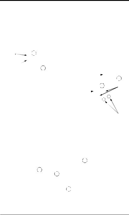
Removing and Replacing the Digital Operator
To remove the digital operator from the front cover, push the operator lever in the direction shown by arrow 1 and lift the digital operator in the direction shown by arrow 2 (see Figure 4).
To replace the digital operator, engage the operator onto retaining tabs A in the direction shown by arrow 1 and then onto retaining tabs B in the direction shown by arrow 2, locking the digital operator into place (see Figure 5).
Front Cover |
2 |
|
|
|
|
|
|
Digital Operator |
|
||||
|
1 |
|
|
|
|
|
|
Digital Operator |
|
|
2 |
||
|
|
|||||
|
|
|
|
|
|
|
|
1 |
Retaining |
||||
Figure 4 |
Front Cover |
|
|
Tabs A |
||
Removing the Digital Operator |
|
|||||
Retaining
Tabs B
Figure 5 Replacing the Digital Operator
Removing and Replacing the Front Cover
To remove the front cover, first remove the digital operator (see previous section). Then squeeze the cover on both sides in the direction shown by arrows 2 and lift the cover in the direction shown by arrow 3.
1 
Front Cover 
2 
3 
2 
Figure 6 Removing and Replacing the Front Cover
14 |
VS-616PC5/P5 User’s Manual |

Chapter 1 - Receiving & Installation
Mounting
Dimensions/Heat Loss
Open Chassis Type (IP00)
|
Model |
|
Open Chassis Dimensions in inches (mm) |
|
|
Mass |
Heat Loss (W) |
||||||
Voltage |
CIMR |
|
|
|
|
|
|
|
Heat |
Inside |
Total |
||
W |
H |
D |
W1 |
H1 |
H2 |
lbs (kg) |
|||||||
|
-P5U |
sink |
unit |
||||||||||
|
|
|
|
|
|
|
|
|
|
||||
|
|
|
|
|
|
|
|
|
|
|
|
|
|
|
20P4 |
|
|
|
|
|
|
|
|
15 |
50 |
65 |
|
|
20P7 |
5.51 (140) |
11.02 (280) |
6.30 (160) |
4.96 (126) |
10.47 |
(266) |
0.28 (7) |
6.5 (3) |
25 |
65 |
90 |
|
|
21P5 |
|
|
|
|
|
|
|
|
40 |
80 |
120 |
|
|
22P2 |
5.51 (140) |
11.02 (280) |
7.09 (180) |
4.96 (126) |
10.47 |
(266) |
0.28 (7) |
10 (4.5) |
80 |
60 |
140 |
|
|
23P7 |
135 |
80 |
215 |
|||||||||
|
|
|
|
|
|
|
|
|
|||||
|
25P5 |
7.87 (200) |
11.81 (300) |
8.07 (205) |
7.32 (186) |
11.22 (285) |
0.31 (8) |
12 (5.5) |
210 |
90 |
300 |
||
|
27P5 |
13 (6) |
235 |
110 |
345 |
||||||||
|
|
|
|
|
|
|
|
||||||
230V |
2011 |
9.84 (250) |
14.96 (380) |
8.86 (225) |
9.29 (236) |
14.37 |
(365) |
0.30 (7.5) |
24 (11) |
425 |
160 |
585 |
|
2015 |
525 |
200 |
725 |
||||||||||
|
|
|
|
|
|
|
|
|
|||||
|
2018 |
12.80 (325) |
17.72 (450) |
11.22 (285) |
10.83 (275) |
17.13 |
(435) |
0.30 (7.5) |
62 (28) |
655 |
230 |
885 |
|
|
2022 |
830 |
280 |
1110 |
|||||||||
|
|
|
|
|
|
|
|
|
|||||
|
2030 |
16.73 (425) |
26.57 (675) |
13.78 (350) |
12.60 (320) |
25.59 |
(650) |
0.49 (12.5) |
134 (61) |
1050 |
500 |
1550 |
|
|
2037 |
137 (62) |
1250 |
700 |
1950 |
||||||||
|
2045 |
18.70 (475) |
31.50 (800) |
13.78 (350) |
14.57 (370) |
30.51 |
(775) |
0.49 (12.5) |
176 (80) |
1550 |
750 |
2300 |
|
|
2055 |
1950 |
1000 |
2950 |
|||||||||
|
|
|
|
|
|
|
|
|
|||||
|
2075 |
22.64 (575) |
36.42 (925) |
15.75 (400) |
17.52 (445) |
35.24 (895) |
0.59 (15) |
298 (135) |
2300 |
1300 |
3600 |
||
|
40P4 |
|
|
|
|
|
|
|
6.5 (3) |
10 |
50 |
60 |
|
|
40P7 |
5.51 (140) |
11.02 (280) |
6.30 (160) |
4.96 (126) |
10.47 |
(266) |
0.28 (7) |
20 |
65 |
85 |
||
|
|
||||||||||||
|
41P5 |
|
|
|
|
|
|
|
8.8 (4) |
30 |
80 |
110 |
|
|
42P2 |
|
|
|
|
|
|
|
|
65 |
60 |
125 |
|
|
43P7 |
5.51 (140) |
11.02 (280) |
7.09 (180) |
4.96 (126) |
10.47 |
(266) |
0.28 (7) |
10 (4.5) |
80 |
65 |
145 |
|
|
44P0 |
|
|
|
|
|
|
|
|
120 |
80 |
200 |
|
|
45P5 |
7.87 (200) |
11.81 (300) |
8.07 (205) |
7.32 (186) |
11.22 (285) |
0.31 (8) |
13 (6) |
135 |
85 |
220 |
||
|
47P5 |
240 |
120 |
360 |
|||||||||
|
|
|
|
|
|
|
|
|
|||||
|
4011 |
9.84 (250) |
14.96 (380) |
8.86 (225) |
9.29 (236) |
14.37 |
(365) |
0.30 (7.5) |
24 (11) |
305 |
150 |
455 |
|
|
4015 |
390 |
180 |
570 |
|||||||||
|
|
|
|
|
|
|
|
|
|||||
460V |
4018 |
12.80 (325) |
17.72 (450) |
11.22 (285) |
10.83 (275) |
17.13 |
(435) |
0.30 (7.5) |
60 (27) |
465 |
195 |
660 |
|
4022 |
620 |
260 |
880 |
||||||||||
|
|
|
|
|
|
|
|
|
|||||
|
4030 |
|
|
|
|
|
|
|
|
705 |
315 |
1020 |
|
|
4037 |
12.80 (325) |
24.61 (625) |
11.22 (285) |
10.83 (275) |
24.02 |
(610) |
0.30 (7.5) |
97 (44) |
875 |
370 |
1245 |
|
|
4045 |
|
|
|
|
|
|
|
|
970 |
415 |
1385 |
|
|
4055 |
17.91 (455) |
32.28 (820) |
13.78 (350) |
13.78 (350) |
31.30 |
(795) |
0.49 (12.5) |
174 (79) |
1110 |
710 |
1820 |
|
|
4075 |
176 (80) |
1430 |
890 |
2320 |
||||||||
|
4110 |
22.64 (575) |
36.42 (925) |
14.76 (375) |
17.52 (445) |
35.24 |
(895) |
0.59 (15) |
298 (135) |
1870 |
1160 |
3030 |
|
|
4160 |
15.75 (400) |
320 (145) |
2670 |
1520 |
4190 |
|||||||
|
|
|
|
|
|
|
|||||||
|
4185 |
37.40 (950) |
57.09 (1450) |
17.13 (435) |
29.53 (750) |
55.12 (1400) |
0.98 (25) |
794 (360) |
3400 |
1510 |
4910 |
||
|
4220 |
4740 |
2110 |
6850 |
|||||||||
|
|
|
|
|
|
|
|
|
|||||
|
4300 |
37.80 (960) |
62.99 (1600) |
17.91 (455) |
29.53 (750) |
61.02 (1550) |
0.98 (25) |
926 (420) |
6820 |
2910 |
9730 |
||
VS-616PC5/P5 User’s Manual |
15 |

Chapter 1 - Receiving & Installation
Mounting
Enclosed Type (NEMA 1, IP20)
|
Model |
|
NEMA 1 Dimensions in inches (mm) |
|
|
Mass |
||||
Voltage |
(CIMR- |
|
|
|
|
|
|
|
||
W |
H |
D |
W1 |
H1 |
H2 |
lbs (kg) |
||||
|
P5U) |
|||||||||
|
|
|
|
|
|
|
|
|
||
|
20P4 |
|
|
|
|
|
|
|
|
|
|
20P7 |
5.51 (140) |
11.02 (280) |
6.30 (160) |
4.96 (126) |
10.47 |
(266) |
0.28 (7) |
6.5 (3) |
|
|
21P5 |
|
|
|
|
|
|
|
|
|
|
22P2 |
5.51 (140) |
11.02 (280) |
7.09 (180) |
4.96 (126) |
10.47 |
(266) |
0.28 (7) |
10 (4.5) |
|
|
23P7 |
|||||||||
|
|
|
|
|
|
|
|
|
||
|
25P5 |
7.87 (200) |
11.81 (300) |
8.07 (205) |
7.32 (186) |
11.22 (285) |
0.31 (8) |
12 (5.5) |
||
|
27P5 |
13 (6) |
||||||||
|
|
|
|
|
|
|
|
|||
230V |
2011 |
9.84 (250) |
14.96 (380) |
8.86 (225) |
9.29 (236) |
14.37 |
(365) |
0.30 (7.5) |
24 (11) |
|
2015 |
15.75 (400) |
1.08 (27.5) |
||||||||
|
|
|
|
|
|
|
||||
|
2018 |
12.99 (330) |
24.02 (610) |
11.22 (285) |
10.83 (275) |
17.13 |
(435) |
3.44 (87.5) |
71 (32) |
|
|
2022 |
26.57 (675) |
6.00 (152.5) |
|||||||
|
|
|
|
|
|
|
||||
|
2030 |
16.93 (430) |
38.78 (985) |
13.78 (350) |
12.60 (320) |
25.59 |
(650) |
8.37 (212.5) |
148 (67) |
|
|
2037 |
150 (68) |
||||||||
|
|
|
|
|
|
|
|
|||
|
2045 |
18.90 (480) |
43.70 (1110) |
13.78 (350) |
14.57 (370) |
30.51 |
(775) |
8.37 (212.5) |
192 (87) |
|
|
2055 |
|||||||||
|
|
|
|
|
|
|
|
|
||
|
2075 |
22.83 (580) |
50.79 (1290) |
15.75 (400) |
17.52 (445) |
35.24 |
(895) |
10.63 (270) |
320 (145) |
|
|
40P4 |
|
|
|
|
|
|
|
6.5 (3) |
|
|
40P7 |
5.51 (140) |
11.02 (280) |
6.30 (160) |
4.96 (126) |
10.47 |
(266) |
0.28 (7) |
||
|
|
|||||||||
|
41P5 |
|
|
|
|
|
|
|
8.8 (4) |
|
|
42P2 |
|
|
|
|
|
|
|
|
|
|
43P7 |
5.51 (140) |
11.02 (280) |
7.09 (180) |
4.96 (126) |
10.47 |
(266) |
0.28 (7) |
10 (4.5) |
|
|
44P0 |
|
|
|
|
|
|
|
|
|
|
45P5 |
7.87 (200) |
11.81 (300) |
8.07 (205) |
7.32 (186) |
11.22 (285) |
0.31 (8) |
13 (6) |
||
|
47P5 |
|||||||||
|
|
|
|
|
|
|
|
|
||
|
4011 |
9.84 (250) |
14.96 (380) |
8.86 (225) |
9.29 (236) |
14.37 |
(365) |
0.30 (7.5) |
24 (11) |
|
460V |
4015 |
|||||||||
|
|
|
|
|
|
|
|
|||
|
4018 |
12.99 (330) |
24.02 (610) |
11.22 (285) |
10.83 (275) |
17.13 |
(435) |
3.44 (87.5) |
68 (31) |
|
|
4022 |
|||||||||
|
|
|
|
|
|
|
|
|
||
|
4030 |
|
30.91 (785) |
|
|
|
|
3.44 (87.5) |
|
|
|
4037 |
12.99 (330) |
11.22 (285) |
10.83 (275) |
24.02 |
(610) |
106 (48) |
|||
|
|
|
||||||||
|
4045 |
33.46 (850) |
6.00 (152.5) |
|||||||
|
|
|
|
|
|
|
||||
|
4055 |
18.11 (460) |
44.49 (1130) |
13.78 (350) |
13.78 (350) |
31.30 |
(795) |
8.37 (212.5) |
187 (85) |
|
|
4075 |
190 (86) |
||||||||
|
|
|
|
|
|
|
|
|||
|
4110 |
22.83 (580) |
50.79 (1290) |
14.76 (375) |
17.52 (445) |
35.24 |
(895) |
10.63 (270) |
320 (145) |
|
|
4160 |
15.75 (400) |
342 (155) |
|||||||
|
|
|
|
|
|
|
||||
16 |
VS-616PC5/P5 User’s Manual |

Chapter 1 - Receiving & Installation
Mounting
W1
W
H1 |
|
H |
|
||
|
|
|
|
|
|
 H2
H2
D
Front View |
Side View |
Figure 7 VS-616PC5/P5 Dimension Diagram
Clearances
When mounting the VS-616PC5/P5, allow sufficient clearances for effective cooling as shown below:
1.97in (50mm) |
|
|
|
|
|
|
|
|
Air |
||
|
|
|
|
|
|
|
|
||||
|
|
|
|
4.72in (120mm) |
|||||||
|
|
|
|
|
|
|
|
|
|
|
|
|
|
|
|
|
|
|
|
|
|
|
|
|
|
|
|
|
|
|
|
|
|
|
|
|
|
|
|
|
|
|
|
|
|
|
|
|
|
|
|
|
|
|
|
|
|
|
|
|
|
|
|
|
|
|
|
|
|
|
|
|
|
|
|
|
|
|
|
|
|
|
|
|
|
|
|
|
|
|
|
|
|
|
|
|
|
|
|
|
|
|
|
|
|
|
|
|
|
|
|
|
|
|
|
|
|
|
|
1.18in (30mm) |
4.72in (120mm) |
|
1.97in (50mm) |
||
Air |
Front View |
Side View |
Figure 8 VS-616PC5/P5 Clearances
Notes:
1)The required clearances at the top, bottom, and both sides of the inverter are the same for both open chassis and NEMA 1 enclosures.
2)For inverter models 25HP and less (230V & 460V), remove the top and bottom covers to convert NEMA 1 units to open chassis
3)Allowable intake air temperature:
Open chassis: |
14°F to 113°F (-10°C to +45°C) |
NEMA 1: |
14°F to 104°F (-10°C to 40°C) |
4)When mounting units in an enclosure, install a fan or other cooling device to limit the air temperature within the inverter to below 113°F (45°C).
VS-616PC5/P5 User’s Manual |
17 |

Chapter 1 - Receiving & Installation
Wiring
1.5 WIRING
! CAUTION
PRECAUTIONS
1)Do not connect or disconnect wiring, or perform signal checks while the power supply is turned ON.
2)Connect the power supply wiring to terminals L1, L2 and L3 on the main circuit input section. DO NOT connect the power supply wiring to output terminals T1, T2 and T3.
3)Connect the motor wiring to terminals T1, T2 and T3 on the main circuit output section.
4)Never touch the output circuit directly or place the output line in contact with the inverter enclosure.
5)Do not connect a phase-advancing capacitor or an LC/RC noise filter to the output circuit.
6)The motor wiring must be less than 328ft (100m) in length and in a separate conduit from the input power wiring.
7)Control wiring must be less than 164ft (50m) in length and in a separate conduit from both the motor wiring and the power wiring.
8)Tighten the screws on the main circuit and control circuit terminals.
9)Low voltage wires shall be wired with Class 1 wiring.
10)Please observe national electrical code (NEC) when wiring electrical devices.
Failure to observe these precautions may result in equipment damage.
Inspection
After wiring is complete, verify that:
All wiring is correctly installed.
Excess screws and wire clippings are removed from inside of the unit. Screws are securely tightened.
Exposed wire has no contact with other wiring or terminals.
18 |
VS-616PC5/P5 User’s Manual |
Chapter 1 - Receiving & Installation
Wiring
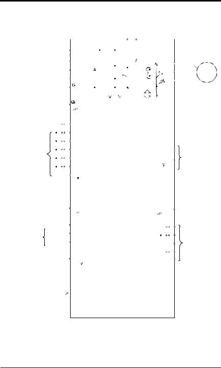
VS-616PC5 Standard Connection Diagram
|
|
|
|
|
|
|
|
|
|
|
|
|
|
|
|
|
|
|
|
|
|
|
|
|
|
|
|
|
|
|
|
|
|
|
|
|
|
|
|
|
|
|
|
|
|
|
|
230V: Models 20P4 through 27P5 |
|||||||
|
|
|
|
|
|
|
|
|
|
|
|
|
|
|
|
|
|
|
|
|
|
|
|
|
|
|
|
|
|
|
|
|
|
|
|
|
|
|
|
|
|
|
|
|
|
|
|
460V: Models 40P4 through 4015 |
|||||||
|
|
|
|
|
|
|
|
|
|
|
|
|
|
|
|
|
|
|
|
|
|
|
|
|
|
|
|
|
|
|
|
|
|
|
|
|
|
|
|
|
|
|
|
|
|
|
|
|
|
|
|
|
|
|
|
DC Link Reactor (option) |
Å1 |
|
|
|
|
|
|
|
|
|
|
|
|
|
|
|
|
|
|
|
|
|
|
|
|
B1 |
B2 |
|
|
|
|
|
|
|
|
||||||||||||||||||||
|
|
|
|
|
|
|
|
Å2 |
|
|
|
|
|
|
|
|
|
|
|
|
|
|
|
|
|
|
|
|
|
|
|
|
|
|
|
|
|
|
|
|
|
|
|
|
|
|
|
|
|
|
|
|
|
||
|
|
|
|
|
|
|
|
|
L1 |
|
|
|
|
|
|
|
|
|
|
|
|
|
|
|
|
|
|
|
|
|
|
|
|
|
|
|
|
|
|
|
|
|
|
|
|
T1 |
|
|
|
||||||
|
|
|
|
|
|
|
|
|
L2 |
|
|
|
|
|
|
|
|
|
|
|
|
|
|
|
|
|
|
|
|
|
|
|
|
|
|
|
|
|
|
|
|
|
|
|
|
T2 |
|
|
IM |
||||||
|
|
|
|
|
|
|
|
|
|
|
|
|
|
|
|
|
|
|
|
|
|
|
|
|
|
|
|
|
|
|
|
|
|
|
|
|
|
|
|
|
|
|
|
|
|
|
|||||||||
|
|
|
|
|
|
|
|
|
L3 |
|
|
|
|
|
|
|
|
|
|
|
|
|
|
|
|
|
|
|
|
|
|
|
|
|
|
|
|
|
|
|
|
|
|
|
|
T3 |
|
|
|
||||||
|
|
|
|
|
|
|
|
|
|
|
|
|
|
|
|
|
|
|
|
|
|
|
|
|
|
|
|
|
|
|
|
|
|
|
|
|
|
|
|
|
|
|
|
|
|
|
|
||||||||
Ground |
|
|
|
|
|
|
|
|
|
|
|
|
|
|
|
|
|
|
|
|
|
|
|
|
|
|
|
|
|
|
|
|
|
|
|
|
|
|
|
|
|
|
|
|
|
|
|
|
|||||||
|
|
|
|
|
|
|
|
|
|
|
|
|
|
|
|
|
|
|
|
|
|
|
|
|
|
|
|
|
|
|
|
|
|
|
|
|
|
|
|
|
|
|
|
|
|
|
|
||||||||
|
|
|
|
|
|
|
|
|
|
|
|
|
|
|
|
|
|
|
|
|
|
|
|
|
|
|
|
|
|
|
|
|
|
|
|
|
|
|
|
|
|
|
|
|
|
|
|
||||||||
|
|
|
|
|
|
|
|
|
|
|
|
|
|
|
|
|
|
|
|
|
|
|
|
|
|
|
|
|
|
|
|
|
|
|
|
|
|
|
|
|
|
|
|
|
|
|
|
||||||||
|
|
|
|
|
|
|
|
|
|
|
|
|
|
|
|
|
|
|
|
|
|
|
|
|
|
|
|
|
|
|
|
|
|
|
|
|
|
|
|
|
|
|
|
|
|
|
|
||||||||
|
|
|
|
|
|
|
|
|
|
|
|
|
|
|
|
|
|
Gate Drive |
|
|
|
|
|
|
|
|
|
|
|
|
|
|
|
|
|||||||||||||||||||||
230V units: 100W or less |
|
|
|
|
|
|
|
|
|
|
|
|
|
|
|
|
|
|
|
|
|
|
|
|
|
|
|
|
|
|
|
|
|
|
|
||||||||||||||||||||
460V units: 10W or less |
|
|
|
|
|
|
|
|
|
|
|
|
|
|
|
|
|
|
|
|
|
|
|
|
|
|
|
|
|
|
|
|
|
|
|
|
|
|
|
|
|
|
|
|
|
|
|
|
|||||||
|
|
|
|
|
|
|
|
|
|
|
|
|
|
|
|
|
|
|
|
|
|
|
|
|
|
|
|
|
|
|
|
|
|
|
|
|
|
|
|
|
|
|
|
|
|
|
|
||||||||
|
|
|
|
|
|
|
|
|
S1 - Fixed |
|
|
|
|
|
|
|
|
|
|
|
|
|
|
|
|
|
|
|
|
|
|
|
|
|
|
|
|
|
|
|
|
|
|
|
|
|
|
|
|||||||
|
|
|
|
|
|
|
|
|
|
|
|
|
|
|
|
|
|
|
|
|
|
|
|
|
|
|
|
|
|
|
|
|
|
|
|
|
|
|
|
|
|
|
|
|
|
|
|
||||||||
|
|
|
|
|
|
|
|
|
S2 |
|
|
|
|
|
|
|
|
|
|
|
|
|
|
|
|
|
|
|
|
|
|
|
|
|
|
|
|
|
|
|
|
|
|
|
|
|
|
|
|||||||
|
|
|
|
|
|
|
|
|
|
|
|
|
|
|
|
|
|
|
|
|
|
|
|
|
|
|
|
|
|
|
|
|
|
|
|
|
|
|
|
|
|
|
|
|
|
|
|
||||||||
|
|
|
|
|
|
|
|
|
S3 |
|
|
|
|
|
|
|
|
|
|
|
|
|
|
|
|
|
|
|
|
|
|
|
|
|
|
|
|
|
|
|
|
|
|
|
|
|
|
|
|||||||
|
|
|
|
|
|
|
|
|
|
|
|
|
|
|
|
|
|
|
|
|
|
|
|
|
|
|
|
|
|
|
|
|
|
|
|
|
|
|
|
|
|
|
|
|
|
|
|
||||||||
|
|
|
|
|
|
|
|
|
|
|
|
|
|
|
|
|
|
|
|
|
|
|
|
|
|
|
|
|
|
|
|
|
|
|
|
|
|
|
|
|
|
|
|
|
|
|
|
||||||||
|
|
|
|
|
|
|
|
|
S4 |
|
|
|
|
|
|
|
|
|
|
|
|
|
|
|
|
|
|
|
|
|
|
|
|
|
|
0~10V |
|
|
AM |
|
|
|
|||||||||||||
|
|
|
|
|
|
|
|
|
|
|
|
|
|
|
|
|
|
|
|
|
|
|
|
|
|
|
|
|
|
|
|
|
|
|
|
|
|||||||||||||||||||
Multi-Function |
|
|
|
|
|
|
|
|
|
|
|
|
|
|
|
|
|
|
|
|
|
|
|
|
PWM |
|
|
Multi-Function |
|||||||||||||||||||||||||||
|
|
S5 |
|
|
|
|
|
|
|
|
|
|
|
|
|
|
|
|
|
|
|
|
|
|
|
|
|
|
|
|
|
|
|||||||||||||||||||||||
Contact Inputs |
|
|
|
|
|
|
|
|
|
|
|
|
|
|
|
|
|
|
|
|
|
|
|
|
|
|
|
|
|
(Com) AC |
|||||||||||||||||||||||||
|
|
|
|
|
|
|
|
|
|
|
|
|
|
|
|
|
|
|
|
|
|
|
|
|
8 bit |
|
|
|
|
||||||||||||||||||||||||||
|
|
|
|
|
|
|
|
|
|
|
|
|
|
|
|
|
|
|
|
|
|
|
|
|
|
|
|
|
Analog Outputs |
||||||||||||||||||||||||||
|
|
|
|
S6 |
|
|
|
|
|
|
|
|
|
|
|
|
|
|
|
|
|
|
|
|
|
||||||||||||||||||||||||||||||
|
|
|
|
|
|
|
|
|
|
|
|
|
|
|
|
|
|
|
|
|
|
|
|
|
|
|
|
|
|
|
|
|
|
|
|
|
|
|
|
|
|
|
|
|
|||||||||||
|
|
|
|
|
|
|
|
|
|
|
|
|
|
|
|
|
|
|
|
|
|
|
|
|
|
|
|
|
|
|
|
|
|
|
|
|
|
|
|
|
|
|
|
|
|
|
|
||||||||
|
|
|
|
|
|
|
|
|
SC (Com) |
|
|
|
|
|
|
|
|
|
|
|
|
|
|
|
|
|
|
|
|
|
|
|
|
|
|
|
|
|
|
|
|
|
|
|
|
|
|
|
|||||||
|
|
|
|
|
|
|
|
|
|
|
|
|
|
|
|
|
|
|
|
|
|
|
|
|
|
|
|
|
|
|
|
|
|
|
|
|
|
|
|
|
|
|
|
|
|
|
|
||||||||
|
|
|
|
|
|
|
|
|
|
|
|
|
|
|
|
|
|
|
|
|
|
|
|
|
|
|
|
|
|
|
|
|
|
|
|
|
|
|
|
|
|
|
|
|
|
|
|
|
|
|
|
|
|
|
|
|
|
|
|
|
|
|
|
|
|
|
|
|
|
|
|
|
|
|
|
|
|
|
|
|
|
|
|
|
|
|
|
|
|
|
|
|
|
|
|
|
|
|
|
|
|
|
|
|
|
|
|
|
|
|
|
|
|
|
|
|
|
|
G |
|
|
|
|
|
|
|
|
|
G |
|
|
|
|||||
|
|
|
|
|
|
|
FS |
|
|
(+15V) |
|
|
|
|
|
|
|
MA |
|
|
|
||||
|
|
|
|
|
|
|
|
|
|
|
|
|
|
|
|
|
|||||||||
|
0~+10V |
|
FV |
(20kW) |
|
|
|
|
|
|
|
|
|
|
|
|
|
||||||||
Analog Inputs |
|
|
A/D |
|
|
|
|
|
MB |
|
|
|
|||||||||||||
|
|
|
|
|
|
|
|
(250W) |
|
|
|
|
|
|
|
|
|
||||||||
Input FI selectable |
4~20mA |
|
FI |
|
|
|
|
|
|
|
|
|
|
|
Multi-Function |
||||||||||
|
|
|
|
|
|
|
MC |
|
|
||||||||||||||||
4~20mA |
|
|
|
|
|
|
|
|
|
|
|
|
10 bit |
|
|
|
|
|
|
|
|||||
|
|
|
|
|
|
|
|
|
|
|
|
|
|
|
|
|
|
M1 |
|
|
Contact Outputs |
||||
or |
|
|
|
|
|
|
|
|
|
|
|
|
|
|
|
|
|
|
|
|
|
250VAC, 1A or less |
|||
|
|
|
|
|
|
|
|
|
|
|
|
|
|
|
|
|
|
|
|
|
|
|
|
||
0~10V |
|
|
|
|
|
|
FC |
(0V) |
|
|
|
|
|
|
|
M2 |
|
|
30VDC, 1A or less |
||||||
|
|
|
|
|
|
|
|
|
|
|
|
|
|
|
|
|
|
|
|
|
|
|
|
|
|
|
|
|
|
|
|
|
|
|
|
|
|
|
|
|
|
|
|
|
|
|
|
|
|
|
|
|
|
|
|
|
|
|
|
|
|
|
|
|
|
Digital |
|
|
|
|
|
|
|
|
|
|
|
Serial Port |
|
|
|
|
|
|
|
RS-232 |
|
|
Operator |
|
|
|
|
|
|
|
|
|
|
||||
|
|
|
|
|
|
|
|
|
|
|
|
|
|
|
|
|
|
|
|
|
|||||
|
|
|
|
|
|
|
|
|
|
|
|
|
|
|
|
|
|
|
|
|
|||||
|
|
|
|
|
|
(10-pin) |
|
|
|
|
|
|
|
|
|
|
|
|
|
|
|||||
|
|
|
|
|
|
|
|
|
|
|
|
|
|
|
|
|
|
|
|
|
|
|
|||
|
|
|
|
|
|
|
|
|
|
|
|
|
|
|
|
|
|
|
|
|
|
||||
|
|
|
|
|
|
|
|
|
|
|
|
|
|
|
|
|
|
|
|
|
|
|
|
|
|
Figure 9 VS-616PC5 Terminal Diagram
VS-616PC5/P5 User’s Manual |
19 |
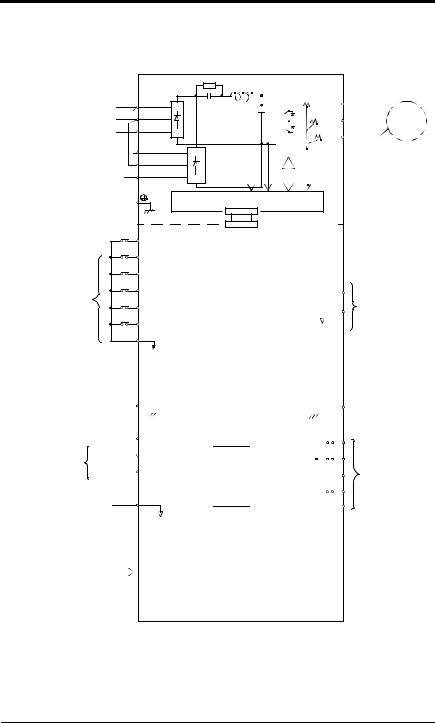
Chapter 1 - Receiving & Installation
Wiring
VS-616P5 Standard Connection Diagram
230V: Models 2018 through 2075 460V: Models 4018 through 4160
L1
L2
L3
L11
L21
L31
Ground
230V units: 100Ω or less
460V units: 10Ω or less
S1 - Fixed
S2
S3
S4
Multi-Function
Inputs |
S5 |
S6
SC (Com)
|
|
|
G |
|
|
|
|
|
|
|
|
|
|
|
|
|
|
|
FS |
(+15V) |
|||
|
|
|
|
|
|
|
|
Analog Inputs |
0~+10V |
FV |
(20kΩ) |
|
|||
|
|||||||
|
|
|
|
(250Ω) |
|
||
Input FI selectable |
4~20mA |
FI |
|
||||
4~20mA |
|
|
|
|
|
|
|
or |
|
|
|
|
|
|
|
0~10V |
|
|
FC |
(0V) |
|
||
Serial Port |
|
|
|
RS-232 |
|
|
|
|
(10-pin) |
|
|
|
|
|
|
|
|
|
|
|
|
|
|
T1 |
|
|
|
|
|
|
|
|
|
|
|
|
|
|
|
|
|
|
|
|
|
|
|
|
|
T2 |
|
IM |
|
|
|
|
|
|
|
|
|
|
T3 |
|
|
|
|
|
|
|
|
|
|
|
|
|
|
|
|
|
|
|
|
|
|
|
|
|
|
|
|
|
|
|
|
|
|
|
|
|
|
|
|
|
|
|
|
|
|
|
|
|
|
|
|
|
|
|
|
|
|
|
|
|
|
|
|
|
|
|
|
|
|
|
|
|
|
|
|
|
|
|
|
Gate Drive
|
|
|
|
|
|
|
|
|
|
|
|
|
|
|
|
|
|
|
|
|
|
|
|
|
|
|
|
|
|
|
|
|
|
|
|
|
0~10V |
AM |
|
|||||
|
|
PWM |
|
|
||||||||||
|
|
|
|
(Com) AC |
Multi-Function |
|||||||||
|
|
8 bit |
|
|
Analog Outputs |
|||||||||
|
|
|
|
|
|
|
|
|
|
|
|
|
|
|
|
|
|
|
|
|
|
|
|
|
|
|
|
|
|
|
|
|
|
G |
|
|
|
|||
|
|
|
|
|
MA |
|
|
|
||
|
|
|
|
|
|
|
|
|||
|
|
|
|
|
|
|
|
|
|
|
|
|
|
|
|
MB |
|
|
|
||
A/D |
|
|
|
|
|
|
|
|
|
Multi-Function |
|
|
|
|
MC |
|
|
||||
10 bit |
|
|
|
|
|
|
||||
|
|
|
|
|
|
Relay Outputs |
||||
|
|
|
|
M1 |
|
|
||||
|
|
|
|
|
|
|
||||
|
|
|
|
|
|
|
250VAC, 1A or less |
|||
|
|
|
|
|
|
|
|
|
|
|
|
|
|
|
|
M2 |
|
|
30VDC, 1A or less |
||
|
|
|
|
|
|
|
|
|
|
|
Digital |
|
|
|
|
|
|
|
|
|
|
Operator |
|
|
|
|
|
|
|
|
|
|
|
|
|
|
|
|
|
|
|
|
|
Figure 10 VS-616P5 Terminal Diagram
20 |
VS-616PC5/P5 User’s Manual |
Chapter 1 - Receiving & Installation
Wiring
Main Circuit Wiring
Input Wiring
· Molded-Case Circuit Breaker (MCCB)
Be sure to connect MCCBs or fuses between the AC main circuit power supply and VS-616PC5/P5 input terminals L1, L2 and L3, to protect the power supply wiring.
· Ground Fault Interrupter
When connecting a ground fault interrupter to input terminals L1, L2 and L3, select one that is not affected by high frequency.
Examples: |
NV series by Mitsubishi Electric Co., Ltd. (manufactured |
|
in or after 1988), EGSG series by Fuji Electric Co., Ltd. |
|
(manufactured in or after 1984). |
· Magnetic Contactor (MC)
Inverters can be used without an MC installed on the power supply side. An MC can be used instead of an MCCB to apply the main circuit power supply. However, when an MC is switched OFF on the primary side, dynamic braking does not function and the motor coasts to stop.
The load can be operated/stopped by closing/opening the MC on the primary side. However, frequent switching may cause the inverter to malfunction.
When using a braking resistor unit, use an MC to break the power supply side of the inverter in the event of a dynamic braking overload relay trip. Otherwise, if the inverter malfunctions, the braking resistor unit may be burned out.
· Terminal Block Connection Sequence
Input power supply phases can be connected to any terminal regardless of the order of L1, L2 and L3 on the terminal block.
· AC Reactor
When connecting an inverter (230V/460V, 25HP or less) to a large capacity power supply transformer (600kVA or more), or when switching a phase-advancing capacitor, excessive peak current flows through the input power supply circuit, which may damage the converter section. In such cases, install a DC reactor (optional) between inverter Å1 and Å2 terminals, or an AC reactor (optional) on the input side. Installation of a reactor is also effective for improving power factor on the power supply side.
VS-616PC5/P5 User’s Manual |
21 |

Chapter 1 - Receiving & Installation
Wiring
· Surge Suppressor
For inductive loads (i.e. magnetic contactors, magnetic relays, magnetic valves, solenoids, magnetic brakes, etc.) connected near the inverter, use a surge suppressor across the coils to limit the transients on the supply lines.
Output Wiring
· Motor Connection
Connect motor lead wires to output terminals T1, T2 and T3. Verify that the motor rotates in the forward direction (CCW: counterclockwise when viewed from the motor load side) with the forward run command. If the motor rotation is incorrect, exchange any two of the motor leads.
· Magnetic Starter
Do not connect a magnetic starter or a magnetic contactor to the output circuit. If the motor load is connected or disconnected while the inverter is running, the inverter overcurrent protective circuitry may trip.
· Thermal Overload Relay
An electronic overload protective function (I2t) is incorporated into the inverter. However, when driving several motors with one inverter, or when switching between multiple windings of a multiple winding motor, use an external thermal overload relay(s). In this case, set parameter n034 to “Disabled”.
· Wiring Distance Between Inverter and Motor
If the total wiring distance between inverter and motor is excessively long and the inverter carrier frequency (IGBT switching frequency) is high, harmonic leakage current from the wiring will adversely affect the inverter and peripheral devices. If the wiring distance is long, reduce the inverter carrier frequency as described below. Carrier frequency can be set by parameter n054.
Wiring Distance Between Inverter and Motor
Wiring Distance between |
Up to 164 ft. |
Up to 328 ft. |
More than 328 ft. |
Inverter and Motor |
(50m) |
(100m) |
(100m) |
Carrier Frequency * |
15kHz or less |
10kHz or less |
5kHz or less |
(Set value of parameter n054) |
(6) |
(4) |
(2) |
*Increasing the carrier frequency above the factory default value requires current derating. Contact your Yaskawa representative for details.
22 |
VS-616PC5/P5 User’s Manual |
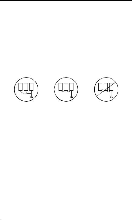
Chapter 1 - Receiving & Installation
Wiring
Grounding
· Ground Resistance
230V class: 100Ω or less, 460V class: 10Ω or less.
·Never ground the VS-616PC5/P5 in common with welding machines, motors, or other high-current electrical equipment. Run all ground wiring in a separate conduit.
·Use ground wiring as specified in “Wire and Terminal Screw Sizes” on page 25, and keep the length as short as possible.
·When using several VS-616PC5/P5 units side by side, ground the units as shown in Figure 10, (a) or (b). Do not loop the wires as shown in (c).
(a) Acceptable |
(b) Acceptable |
(c) Not Acceptable |
Figure 11 Grounding Example of 3 VS-616P5 Inverters
VS-616PC5/P5 User’s Manual |
23 |

Chapter 1 - Receiving & Installation
Wiring
Terminal Functions
230V Class Terminal Functions
Model CIMR-P5U |
20P4 to 27P5 |
|
2011 to 2015 |
|
|
2018 to 2075 |
||
Nominal Motor Output |
0.5 to 10HP |
|
20 to 25HP |
|
|
30 to 125HP |
||
L1 |
|
|
|
|
|
|
||
L2 |
Main circuit input power supply |
|
|
|
||||
L3 |
|
|
|
|
|
Main circuit input |
||
L11 |
|
|
|
|
|
power supply |
||
L21 |
|
--- |
|
|
|
|||
L31 |
|
|
|
|
|
|
||
T1 |
|
|
|
|
|
|
||
T2 |
|
|
Inverter output |
|
|
|
||
T3 |
|
|
|
|
|
|
||
B1 |
Braking resistor unit |
|
|
|
--- |
|||
B2 |
|
|
|
|||||
|
|
|
|
|
|
|||
|
|
|
DC reactor (Å1 - Å2) |
|
DC reactor (Å1 - Å2) |
|
|
|
|
|
|
|
|
|
|||
Å1 |
|
|
|
|||||
DC power supply (Å1 - |
) |
DC power supply (Å1 - |
) |
|
--- |
|||
Å2 |
|
|||||||
|
|
Braking unit (Å3 - |
) |
|
|
|||
Å3 |
--- |
|
|
|
||||
|
|
|
|
|
||||
|
|
|
Ground terminal (Ground resistance: 100W or less) |
|||||
460V Class Terminal Functions
Model CIMR-P5U |
40P4 to 4015 |
|
4018 to 4045 |
|
4055 to 4160 |
4185 to 4300 |
|
Nominal Motor Output |
0.5 to 25HP |
|
30 to 75HP |
|
100 to 250HP |
300 to 500HP |
|
L1 |
Main circuit input |
|
|
|
|
|
Main circuit input |
L2 |
|
|
|
|
|
||
power supply |
|
|
|
|
|
power supply |
|
L3 |
|
Main circuit input power supply |
|
||||
|
|
|
|
||||
L11 |
|
|
|
|
|||
|
|
|
|
|
|
|
|
L21 |
--- |
|
|
|
|
|
--- |
L31 |
|
|
|
|
|
|
|
T1 |
|
|
|
|
|
|
|
T2 |
|
|
Inverter output |
|
|
|
|
T3 |
|
|
|
|
|
|
|
B1 |
Braking resistor unit |
|
|
|
--- |
|
|
B2 |
|
|
|
|
|
||
|
|
|
|
|
|
|
|
|
DC reactor (Å1 - Å2) |
|
|
|
|
|
|
Å1 |
|
|
|
--- |
|
|
|
DC power supply (Å1 - |
) |
|
|
|
|
||
Å2 |
|
|
|
|
|
||
|
|
|
|
|
|
|
|
r |
|
|
|
|
Cooling fan power supply |
||
s 200 |
--- |
|
|
|
(Control power supply) |
||
|
|
|
r - s 200: |
200 to 230 VAC input |
|||
s 400 |
|
|
|
|
|||
|
|
|
|
r - s 400: |
380 to 460 VAC input |
||
|
|
|
|
|
|||
|
Ground terminal (Ground resistance: 10W or less) |
|
|||||
24 |
VS-616PC5/P5 User’s Manual |

Chapter 1 - Receiving & Installation
Wiring
Wire and Terminal Screw Sizes
230V Class Wire Size
Circuit |
Model |
|
|
|
|
Terminal Symbol |
Terminal |
Wire Size * |
Max. Torque |
Wire Type |
||
CIMR- |
|
|
|
|
Screw |
AWG |
mm2 |
lb-in (N·m) |
||||
|
|
|
|
|
|
|
|
|||||
|
P5U20P4 |
L1, L2, L3, , Å1, Å2, B1, B2, T1, T2, T3 |
M4 |
14 - 10 |
2 - 5.5 |
12.4 (1.4) |
|
|||||
|
|
|
|
|
|
|
|
|||||
|
|
|
|
|
|
|
|
|
|
|
|
|
|
P5U20P7 |
L1, L2, L3, |
|
, Å1, Å2, B1, B2, T1, T2, T3 |
M4 |
14 - 10 |
2 - 5.5 |
12.4 (1.4) |
|
|||
|
|
|
||||||||||
|
|
|
|
|
|
|
|
|||||
|
|
|
|
|
|
|
|
|
|
|
|
|
|
|
|
|
|
|
|
|
|
|
|
|
|
|
P5U21P5 |
L1, L2, L3, , Å1, Å2, B1, B2, T1, T2, T3 |
M4 |
14 - 10 |
2 - 5.5 |
12.4 (1.4) |
|
|||||
|
|
|
|
|
|
|
12 - 10 |
3.5 - 5.5 |
|
|||
|
|
|
|
|
|
|
|
|
|
|
||
|
|
|
|
|
|
|
|
|
|
|
||
|
P5U22P2 |
L1, L2, L3, , Å1, Å2, B1, B2, T1, T2, T3 |
M4 |
12 - 10 |
3.5 - 5.5 |
12.4 (1.4) |
|
|||||
|
|
|
|
|
|
|
|
|||||
|
|
|
|
|
|
|
|
|
|
|
|
|
|
P5U23P7 |
L1, L2, L3, , Å1, Å2, B1, B2, T1, T2, T3 |
M4 |
10 |
5.5 |
12.4 (1.4) |
|
|||||
|
|
|
|
|
|
|
|
|||||
|
|
|
|
|
|
|
|
|
|
|
|
|
|
P5U25P5 |
L1, L2, L3, , Å1, Å2, B1, B2, T1, T2, T3 |
M5 |
8 |
8 |
22.1 (2.5) |
|
|||||
|
|
|
|
|
|
|
10 - 8 |
5.5 - 8 |
|
|||
|
|
|
|
|
|
|
|
|
|
|
||
|
P5U27P5 |
L1, L2, L3, , Å1, Å2, B1, B2, T1, T2, T3 |
M5 |
8 |
8 |
22.1 (2.5) |
|
|||||
|
|
|
|
|
|
|
10 - 8 |
5.5 - 8 |
|
|||
|
|
|
|
|
|
|
|
|
|
|
||
|
P5U2011 |
L1, L2, L3, |
|
|
, Å1, Å2, Å3, T1, T2, T3 |
M6 |
4 |
22 |
45.1 (5.1) |
Power cable: |
||
|
|
|
||||||||||
|
|
|
|
|
|
|
8 |
8 |
||||
|
|
|
|
|
|
|
600V vinyl |
|||||
Main |
|
|
|
|
|
|
|
|
|
|||
|
|
|
|
|
|
|
|
|
||||
P5U2015 |
L1, L2, L3, |
|
, Å1, Å2, Å3, T1, T2, T3 |
M8 |
3 |
30 |
90.3 (10.2) |
sheathed wire |
||||
|
|
|||||||||||
|
|
|
|
|
|
|
|
|
|
|
or equivalent |
|
|
|
|
|
|
|
|
M6 |
8 |
8 |
45.1 (5.1) |
||
|
|
|
|
|
|
|
|
|||||
|
|
|
|
|
|
|
|
|
||||
|
P5U2018 |
L1, L2, L3, L11, L21, L31, T1, T2, T3 |
M8 |
3 |
30 |
90.3 (10.2) |
|
|||||
|
|
|
|
|
|
|
6 |
14 |
|
|||
|
|
|
|
|
|
|
|
|
|
|
||
|
|
|
|
|
|
|
|
|
|
|
||
|
P5U2022 |
L1, L2, L3, L11, L21, L31, T1, T2, T3 |
M8 |
2 |
38 |
90.3 (10.2) |
|
|||||
|
|
|
|
|
|
|
6 |
14 |
|
|||
|
|
|
|
|
|
|
|
|
|
|
||
|
P5U2030 |
L1, L2, L3, L11, L21, L31, T1, T2, T3 |
M10 |
4/0 |
100 |
203.6 (23.0) |
|
|||||
|
|
|
|
|
|
|
M8 |
4 |
22 |
90.3 (10.2) |
|
|
|
|
|
|
|
|
|
|
|
||||
|
P5U2037 |
L1, L2, L3, L11, L21, L31, T1, T2, T3 |
M10 |
1/0 x 2P |
60 x 2P |
203.6 (23.0) |
|
|||||
|
|
|
|
|
|
|
M8 |
4 |
22 |
90.3 (10.2) |
|
|
|
|
|
|
|
|
|
|
|
||||
|
P5U2045 |
L1, L2, L3, L11, L21, L31, T1, T2, T3 |
M10 |
1/0 x 2P |
60 x 2P |
203.6 (23.0) |
|
|||||
|
|
|
|
|
|
|
M8 |
4 |
22 |
90.3 (10.2) |
|
|
|
|
|
|
|
|
|
|
|
||||
|
P5U2055 |
L1, L2, L3, L11, L21, L31, T1, T2, T3 |
M10 |
1/0 x 2P |
60 x 2P |
203.6 (23.0) |
|
|||||
|
|
|
|
|
|
|
M8 |
3 |
30 |
90.3 (10.2) |
|
|
|
|
|
|
|
|
|
|
|
||||
|
|
|
|
|
|
|
|
|
||||
|
P5U2075 |
L1, L2, L3, L11, L21, L31, T1, T2, T3 |
M12 |
4/0 x 2P |
100 x 2P |
349.6 (39.5) |
|
|||||
|
|
|
|
|
|
|
M8 |
1 |
50 |
90.3 (10.2) |
|
|
|
|
|
|
|
|
|
|
|
||||
|
|
S1, S2, S3, S4, S5, S6, SC |
|
|
Stranded |
|
Twisted |
|||||
|
Common |
|
|
0.5 - 1.25 |
- |
|||||||
Control |
FV, FI, FS, FC |
- |
20 - 16 |
|
shielded wire |
|||||||
to all |
AM, AC, M1, M2, MA, MB, MC |
|
|
Solid |
|
with Class 1 |
||||||
|
models |
|
|
|
||||||||
|
|
|
|
|
|
|
|
|
0.5 - 1.25 |
|
wiring |
|
|
|
G |
|
|
M3.5 |
20 - 14 |
0.5 - 2 |
8.9 (1.0) |
|
|||
* Wire sizes are based on 75°C copper wire.
Note:
Voltage drop should be considered when determining wire size. Voltage drop can be calculated using the following equation:
Phase-to phase voltage drop (V)
= 
 3 wire resistance (Ω/km) x wiring distance (m) x current (A) x 10-3
Select a wire size so that voltage drop will be less than 2% of the normal rated voltage.
VS-616PC5/P5 User’s Manual |
25 |

Chapter 1 - Receiving & Installation
Wiring
460V Class Wire Size
Circuit |
Model |
|
|
|
|
|
Terminal Symbol |
Terminal |
|
Wire Size * |
Max. Torque |
Wire Type |
|
|
CIMR- |
|
|
|
|
|
|
Screw |
AWG |
mm2 |
lb-in (N·m) |
|
|
|
P5U40P4 |
L1, L2, L3, |
|
, Å1, Å2, B1, B2, T1, T2, T3 |
M4 |
14 |
- 10 |
2 - 5.5 |
12.4 (1.4) |
|
|||
|
|
|
|||||||||||
|
|
|
|
|
|
|
|||||||
|
|
|
|
|
|
|
|
|
|
|
|
|
|
|
P5U40P7 |
L1, L2, L3, |
, Å1, Å2, B1, B2, T1, T2, T3 |
M4 |
14 |
- 10 |
2 - 5.5 |
12.4 (1.4) |
|
||||
|
|
|
|
|
|
|
12 |
- 10 |
3.5 - 5.5 |
|
|||
|
|
|
|
|
|
|
|
|
|
|
|||
|
P5U41P5 |
L1, L2, L3, |
, Å1, Å2, B1, B2, T1, T2, T3 |
M4 |
14 |
- 10 |
2 - 5.5 |
12.4 (1.4) |
|
||||
|
|
|
|
|
|
|
12 |
- 10 |
3.5 - 5.5 |
|
|||
|
|
|
|
|
|
|
|
|
|
|
|||
|
P5U42P2 |
L1, L2, L3, |
, Å1, Å2, B1, B2, T1, T2, T3 |
M4 |
14 |
- 10 |
2 - 5.5 |
12.4 (1.4) |
|
||||
|
|
|
|
|
|
|
12 |
- 10 |
3.5 - 5.5 |
|
|||
|
|
|
|
|
|
|
|
|
|
|
|||
|
P5U43P7 |
L1, L2, L3, |
, Å1, Å2, B1, B2, T1, T2, T3 |
M4 |
14 |
- 10 |
2 - 5.5 |
12.4 (1.4) |
|
||||
|
|
|
|
|
|
|
12 |
- 10 |
3.5 - 5.5 |
|
|||
|
|
|
|
|
|
|
|
|
|
|
|||
|
|
|
|
|
|
|
|
|
|
|
|||
|
P5U45P5 |
L1, L2, L3, , Å1, Å2, B1, B2, T1, T2, T3 |
M4 |
12 |
- 10 |
3.5 - 5.5 |
12.4 (1.4) |
|
|||||
|
|
|
|
|
|
|
|
||||||
|
|
|
|
|
|
|
|
|
|
|
|
||
|
P5U47P5 |
L1, L2, L3, , Å1, Å2, B1, B2, T1, T2, T3 |
M5 |
8 - 6 |
8 - 14 |
22.1 (2.5) |
|
||||||
|
|
|
|
|
|
|
|
||||||
|
|
|
|
|
|
|
|
|
|
|
|
|
|
|
P5U4011 |
L1, L2, L3, |
, Å1, Å2, B1, B2, T1, T2, T3 |
M5 |
8 |
- 6 |
8 - 14 |
22.1 (2.5) |
|
||||
|
|
|
|
|
|
|
M6 |
8 - 6 |
8 - 14 |
45.1 (5.1) |
|
||
|
|
|
|
|
|
|
|
|
|||||
|
P5U4015 |
L1, L2, L3, |
, Å1, Å2, B1, B2, T1, T2, T3 |
M5 |
8 |
- 6 |
8 - 14 |
22.1 (2.5) |
|
||||
|
|
|
|
|
|
|
M6 |
8 - 6 |
8 - 14 |
45.1 (5.1) |
|
||
|
|
|
|
|
|
|
|
|
|||||
|
P5U4018 |
L1, L2, L3, L11, L21, L31, T1, T2, T3 |
M6 |
|
6 |
14 |
45.1 (5.1) |
|
|||||
|
|
|
|
|
|
|
M8 |
8 - 6 |
8 - 14 |
90.3 (10.2) |
|
||
|
|
|
|
|
|
|
|
|
|||||
|
P5U4022 |
L1, L2, L3, L11, L21, L31, T1, T2, T3 |
M6 |
|
4 |
22 |
45.1 (5.1) |
|
|||||
|
|
|
|
|
|
|
M8 |
|
4 |
22 |
90.3 (10.2) |
|
|
|
|
|
|
|
|
|
|
|
|
||||
|
P5U4030 |
L1, L2, L3, L11, L21, L31, T1, T2, T3 |
M8 |
|
4 |
22 |
90.3 (10.2) |
Power cable: |
|||||
|
|
|
|
|
|
|
|
4 |
22 |
||||
|
|
|
|
|
|
|
|
|
|
|
600V vinyl |
||
Main |
|
L1, L2, L3, L11, L21, L31, T1, T2, T3 |
|
|
3 |
30 |
|
||||||
P5U4037 |
M8 |
|
90.3 (10.2) |
sheathed wire |
|||||||||
|
|
|
|
|
|
|
|
4 |
22 |
||||
|
|
|
|
|
|
|
|
|
|
|
or equivalent |
||
|
|
|
|
|
|
|
|
|
|
|
|||
|
P5U4045 |
L1, L2, L3, L11, L21, L31, T1, T2, T3 |
M8 |
|
1 |
50 |
90.3 (10.2) |
||||||
|
|
|
|||||||||||
|
|
|
|
|
|
|
|
3 |
30 |
|
|||
|
|
|
|
|
|
|
|
|
|
|
|
||
|
|
|
|
|
|
|
|
|
|
|
|
||
|
P5U4055 |
L1, L2, L3, L11, L21, L31, T1, T2, T3 |
M10 |
4/0 |
100 |
203.6 (23.0) |
|
||||||
|
|
|
|
|
|
|
M8 |
|
1 |
50 |
90.3 (10.2) |
|
|
|
|
|
|
|
|
|
|
|
|
||||
|
P5U4075 |
L1, L2, L3, L11, L21, L31, T1, T2, T3 |
M10 |
1/0 x 2P |
60 x 2P |
203.6 (23.0) |
|
||||||
|
|
|
|
|
|
|
M8 |
1/0 |
60 |
90.3 (10.2) |
|
||
|
|
|
|
|
|
|
|
|
|||||
|
P5U4110 |
L1, L2, L3, L11, L21, L31, T1, T2, T3 |
M10 |
1/0 x 2P |
60 x 2P |
203.6 (23.0) |
|
||||||
|
|
|
|
|
|
|
M8 |
1/0 |
60 |
90.3 (10.2) |
|
||
|
|
|
|
|
|
|
|
|
|||||
|
P5U4160 |
L1, L2, L3, L11, L21, L31, T1, T2, T3 |
M12 |
4/0 x 2P |
100 x 2P |
349.6 (39.5) |
|
||||||
|
|
|
|
|
|
|
M8 |
4/0 |
100 |
90.3 (10.2) |
|
||
|
|
|
|
|
|
|
|
|
|||||
|
|
L1, L2, L3, |
, Å1, Å3, T1, T2, T3 |
M16 |
650MCM |
325 x 2P |
867.4 (98.0) |
|
|||||
|
P5U4185 |
|
|
|
|
|
|
|
x 2P |
|
|
|
|
|
|
|
|
|
|
|
M8 |
650MCM |
325 |
90.3 (10.2) |
|
||
|
|
|
|
|
|
|
|
|
|||||
|
|
r, s200, s400 |
|
M4 |
20 |
- 10 |
0.5 - 5.5 |
12.4 (1.4) |
|
||||
|
|
L1, L2, L3, |
, Å1, Å3, T1, T2, T3 |
M16 |
650MCM |
325 x 2P |
867.4 (98.0) |
|
|||||
|
P5U4220 |
|
|
|
|
|
|
|
x 2P |
|
|
|
|
|
|
|
|
|
|
|
M8 |
650MCM |
325 |
90.3 (10.2) |
|
||
|
|
|
|
|
|
|
|
|
|||||
|
|
r, s200, s400 |
|
M4 |
20 |
- 10 |
0.5 - 5.5 |
12.4 (1.4) |
|
||||
|
|
L1, L2, L3, |
, Å1, Å3, T1, T2, T3 |
M16 |
650MCM |
325 x 2P |
867.4 (98.0) |
|
|||||
|
P5U4300 |
|
|
|
|
|
|
|
x 2P |
|
|
|
|
|
|
|
|
|
|
|
M8 |
650MCM |
325 |
90.3 (10.2) |
|
||
|
|
|
|
|
|
|
|
|
|||||
|
|
r, s200, s400 |
|
M4 |
20 |
- 10 |
0.5 - 5.5 |
12.4 (1.4) |
|
||||
|
|
S1, S2, S3, S4, S5, S6, SC |
|
|
|
Stranded |
|
Twisted |
|||||
|
Common |
|
|
|
0.5 - 1.25 |
- |
|||||||
Control |
FV, FI, FS, FC |
- |
20 |
- 16 |
|
shielded wire |
|||||||
to all |
AM, AC, M1, M2, MA, MB, MC |
|
|
|
Solid |
|
with Class 1 |
||||||
|
models |
|
|
|
|
||||||||
|
|
|
|
|
|
|
|
|
|
0.5 - 1.25 |
|
wiring |
|
|
|
|
|
|
|
|
|
|
|
|
|
||
|
|
G |
|
M3.5 |
20 |
- 14 |
0.5 - 2 |
8.9 (1.0) |
|
||||
* Wire sizes are based on 75°C copper wire.
26 |
VS-616PC5/P5 User’s Manual |

Chapter 1 - Receiving & Installation
Wiring
JST Closed Loop Connectors
Wire Size * |
Terminal Screw |
JST Closed-Loop Connectors (Lugs) |
Max. Torque |
||||
AWG |
mm2 |
lb-in (N·m) |
|||||
|
|
|
|||||
20 |
0.5 |
M3.5 |
1.25 |
- 3.5 |
8.9 (1.0) |
||
M4 |
1.25 - 4 |
12.4 |
(1.4) |
||||
|
|
||||||
18 |
0.75 |
M3.5 |
1.25 |
- 3.5 |
8.9 (1.0) |
||
M4 |
1.25 - 4 |
12.4 |
(1.4) |
||||
|
|
||||||
16 |
1.25 |
M3.5 |
1.25 |
- 3.5 |
8.9 (1.0) |
||
M4 |
1.25 - 4 |
12.4 |
(1.4) |
||||
|
|
||||||
|
|
M3.5 |
2 - 3.5 |
8.9 (1.0) |
|||
|
|
M4 |
2 - 4 |
12.4 |
(1.4) |
||
14 |
2 |
M5 |
2 - 5 |
22.1 |
(2.5) |
||
|
|
M6 |
2 - 6 |
45.1 |
(5.1) |
||
|
|
M8 |
2 - 8 |
90.3 (10.2) |
|||
|
|
M4 |
5.5 - 4 |
12.4 |
(1.4) |
||
12 - 10 |
3.5 - 5.5 |
M5 |
5.5 - 5 |
22.1 |
(2.5) |
||
M6 |
5.5 - 6 |
45.1 |
(5.1) |
||||
|
|
||||||
|
|
M8 |
5.5 - 8 |
90.3 (10.2) |
|||
|
|
M5 |
8 - 5 |
22.1 |
(2.5) |
||
8 |
8 |
M6 |
8 - 6 |
45.1 |
(5.1) |
||
|
|
M8 |
8 - 8 |
90.3 (10.2) |
|||
6 |
14 |
M6 |
14 |
- 6 |
45.1 |
(5.1) |
|
M8 |
14 |
- 8 |
90.3 (10.2) |
||||
|
|
||||||
4 |
22 |
M6 |
22 |
- 6 |
45.1 |
(5.1) |
|
M8 |
22 |
- 8 |
90.3 (10.2) |
||||
|
|
||||||
3 - 2 |
30 - 38 |
M8 |
38 |
- 8 |
90.3 (10.2) |
||
1 - 1/0 |
50 - 60 |
M8 |
60 |
- 8 |
90.3 (10.2) |
||
M10 |
60 - 10 |
203.6 |
(23.0) |
||||
|
|
||||||
3/0 |
80 |
M10 |
80 - 10 |
203.6 |
(23.0) |
||
4/0 |
100 |
100 |
- 10 |
203.6 (23.0) |
|||
|
|||||||
4/0 |
100 |
|
100 |
- 12 |
349.6 |
(39.5) |
|
300MCM |
150 |
M12 |
150 |
- 12 |
349.6 |
(39.5) |
|
400MCM |
200 |
|
200 |
- 12 |
349.6 |
(39.5) |
|
650MCM |
325 |
M12 x 2 |
325 |
- 12 |
349.6 |
(39.5) |
|
M16 |
325 |
- 16 |
867.4 |
(98.0) |
|||
|
|
||||||
Note:
The use of a JST closed-loop connector (lug) is recommended to maintain proper clearances. Please contact your Yaskawa representative for more information.
VS-616PC5/P5 User’s Manual |
27 |
 Loading...