


 Loading...
AC Servo Drives
-V Series
USER’S MANUAL
Design and Maintenance
Rotational Motor
MECHATROLINK-III Communications Reference
SGDV SERVOPACK
SGMJV/SGMAV/SGMPS/SGMGV/SGMSV/SGMCS Servomotors
Outline |
1 |
Panel Display and |
2 |
Operation of Digital Operator |
|
Wiring and Connection |
3 |
Operation |
4 |
Adjustments |
5 |
Utility Functions (Fn) |
6 |
Monitor Displays (Un) |
7 |
Fully-closed Loop Control |
8 |
Troubleshooting |
9 |
Appendix |
10 |
MANUAL NO. SIEP S800000 64H

Copyright © 2008 YASKAWA ELECTRIC CORPORATION
All rights reserved. No part of this publication may be reproduced, stored in a retrieval system, or transmitted, in any form, or by any means, mechanical, electronic, photocopying, recording, or otherwise, without the prior written permission of Yaskawa. No patent liability is assumed with respect to the use of the information contained herein. Moreover, because Yaskawa is constantly striving to improve its high-quality products, the information contained in this manual is subject to change without notice. Every precaution has been taken in the preparation of this manual. Nevertheless, Yaskawa assumes no responsibility for errors or omissions. Neither is any liability assumed for damages resulting from the use of the information contained in this publication.

About this Manual
This manual describes information required for designing, testing, adjusting, and maintaining Σ-V Series SERVOPACKs.
Keep this manual in a location where it can be accessed for reference whenever required. Manuals outlined on the following page must also be used as required by the application.
Description of Technical Terms
The following table shows the meanings of terms used in this manual.
Term |
Meaning |
|
Cursor |
Input position indicated by Digital Operator |
|
|
|
|
Servomotor |
Σ-V Series SGMJV, SGMAV, SGMPS, SGMGV, SGMSV, or SGMCS |
|
(Direct Drive) servomotor |
||
|
||
|
|
|
SERVOPACK |
Σ-V Series SGDV servo amplifier |
|
|
|
|
Servo Drive |
A set including a servomotor and SERVOPACK (i.e., a servo ampli- |
|
fier) |
||
|
||
|
|
|
Servo System |
A servo control system that includes the combination of a servo drive |
|
with a host controller and peripheral devices |
||
|
||
|
|
|
M-III Model |
MECHATROLINK-III communications reference used for SERVO- |
|
PACK interface |
||
|
||
|
|
|
Servo ON |
Power to motor ON |
|
|
|
|
Servo OFF |
Power to motor OFF |
|
|
|
|
Base Block (BB) |
Power supply to motor is turned OFF by shutting off the base current |
|
to the power transistor in the current amplifier. |
||
|
||
|
|
|
Servo Lock |
A state in which the motor is stopped and is in position loop with a |
|
position reference of 0. |
||
|
||
|
|
|
Main Circuit Cable |
Cables which connect to the main circuit terminals, including main |
|
circuit power supply cables, control power supply cables, servomotor |
||
|
main circuit cables, and others. |
|
|
|
IMPORTANT Explanations
The following icon is displayed for explanations requiring special attention.
•Indicates important information that should be memorized, as well as precautions, such as alarm displays, that do not involve potential damage to equipment.
iii

Notation Used in this Manual
•Notation for Reverse Signals
The names of reverse signals (i.e., ones that are valid when low) are written with a forward slash (/) before the signal name.
Notation Example
BK = /BK
•Notation for Parameters
The notation depends on whether the parameter requires a value setting (parameter for numeric settings) or requires the selection of a function (parameter for selecting functions).
• Parameters for Numeric Settings
Control methods for which the parameter applies.
|
|
|
Speed |
|
: Speed control |
Position |
|
: Position control |
Torque |
: Torque control |
|||||||
|
|
|
|
|
|
|
|
|
|
|
|
|
|
|
|
|
|
|
Emergency Stop Torque |
|
|
|
|
|
|
|
|
|
|
|
|
|
|||
|
|
|
|
Speed |
|
|
Position |
|
Torque |
|
|
|
|||||
Pn406 |
|
|
|
|
|
|
|
|
|
|
|
|
|
|
|
|
|
Setting Range |
Setting Unit |
|
Factory Setting |
|
|
When Enabled |
|
Classification |
|||||||||
|
|
|
|
|
|||||||||||||
|
0% to 800% |
1% |
|
|
800 |
|
|
After change |
|
Setup |
|||||||
Parameter |
|
|
number |
Indicates the |
Indicates the |
Indicates the setting |
minimum setting unit |
parameter setting |
for the parameter. |
before shipment. |
|
range for the parameter. |
|
|
• Parameters for Selecting Functions
Indicates when a |
Indicates the |
|
change to the |
||
parameter |
||
parameter will be |
||
classification. |
||
effective. |
||
|
|
Parameter |
Meaning |
When Enabled |
Classification |
|
|
|
n. 0 |
Uses the absolute encoder as an |
|
|
Pn002 |
|
[Factory setting] |
absolute encoder. |
After restart |
Setup |
|
. 1 |
Uses the absolute encoder as an |
|||
|
|
|
|
||
|
|
|
|
|
|
Parameter number
The notation “n. ” indicates a parameter for selecting functions. Each corresponds to the setting value of that digit. The notation shown here means that the third digit is 1.
This section explains the selections for the function.
Rotation
Notation Example
Digital Operator Display (Display Example for Pn002) |
|
|
MECHA |
||||||||||||||||||||
|
|
|
|
|
|
|
|
|
|
|
|
|
|
|
|
|
|
|
|
|
|
|
|
|
|
|
|
|
|
|
|
|
|
|
|
|
|
|
|
|
|
Digit Notation |
|
|
Setting Notation |
|
|
|
|
|
|
|
|
|
|
|
|
|
|
|
|
|
|
Notation |
|
Meaning |
|
Notation |
Meaning |
|
|
|
|
|
|
|
|
|
|
|
|
|
|
|
|
|
|
1st digit |
Pn002.0 |
|
Indicates the value for the |
|
Pn002.0 = x |
Indicates that the value for the |
|
|
|
|
|
|
|
|
|
|
|
|
|
|
|
|
|
|
1st digit of parameter Pn002. |
|
or n. x |
1st digit of parameter Pn002 is x. |
|||
|
|
|
|
|
|
|
|
|
|
|
|
|
|
|
|
|
|
|
|
||||
|
|
|
|
|
|
|
|
|
|
|
|
|
|
|
|
2nd digit |
Pn002.1 |
|
Indicates the value for the |
|
Pn002.1 = x |
Indicates that the value for the |
|
|
|
|
|
|
|
|
|
|
|
|
|
|
|
|
|
|
2nd digit of parameter Pn002. |
|
or n. x |
2nd digit of parameter Pn002 is x. |
|
||
|
|
|
|
|
|
|
|
|
|
|
|
|
|
|
|
|
|
|
|
||||
|
|
|
|
|
|
|
|
|
|
|
|
|
|
|
|
3rd digit |
Pn002.2 |
|
Indicates the value for the |
|
Pn002.2 = x |
Indicates that the value for the |
|
|
|
|
|
|
|
|
|
|
|
|
|
|
|
|
|
|
3rd digit of parameter Pn002. |
|
or n. x |
3rd digit of parameter Pn002 is x. |
|
||
|
|
|
|
|
|
|
|
|
|
|
|
|
|
|
|
|
|
|
|
||||
|
|
|
|
|
|
|
|
|
|
|
|
|
|
|
|
4th digit |
Pn002.3 |
|
Indicates the value for the |
|
Pn002.3 = x |
Indicates that the value for the |
|
|
|
|
|
|
|
|
|
|
|
|
|
|
|
|
|
|
4th digit of parameter Pn002. |
|
or n.x |
4th digit of parameter Pn002 is x. |
|
||
|
|
|
|
|
|
|
|
|
|
|
|
|
|
|
|
|
|
|
|
||||
iv

Manuals Related to the Σ-V Series
Refer to the following manuals as required.
|
Selecting |
Ratings and |
System |
Panels and |
Trial |
Trial |
Maintenance |
|
|
Models and |
Operation |
||||||
Name |
and |
|||||||
Peripheral |
Specifications |
Design |
Wiring |
Operation |
and Servo |
|||
|
Inspection |
|||||||
|
Devices |
|
|
|
|
Adjustment |
||
|
|
|
|
|
|
|||
Σ-V Series |
|
|
|
|
|
|
|
|
User's Manual |
|
|
|
|
|
|
|
|
Setup |
|
|
|
|
|
|
|
|
Rotational Motor |
|
|
|
|
|
|
|
|
(No.: SIEP S800000 43) |
|
|
|
|
|
|
|
|
|
|
|
|
|
|
|
|
|
Σ-V Series |
|
|
|
|
|
|
|
|
Product Catalog |
|
|
|
|
|
|
|
|
(No.: KAEP S800000 42) |
|
|
|
|
|
|
|
|
|
|
|
|
|
|
|
|
|
Σ-V Series |
|
|
|
|
|
|
|
|
User's Manual |
|
|
|
|
|
|
|
|
Design and Maintenance |
|
|
|
|
|
|
|
|
Rotational Motor/ |
|
|
|
|
|
|
|
|
MECHATROLINK-III |
|
|
|
|
|
|
|
|
Communications Reference |
|
|
|
|
|
|
|
|
(this manual) |
|
|
|
|
|
|
|
|
|
|
|
|
|
|
|
|
|
Σ-V Series |
|
|
|
|
|
|
|
|
User’s Manual |
|
|
|
|
|
|
|
|
MECHATROLINK-III |
|
|
|
|
|
|
|
|
Standard Servo Profile |
|
|
|
|
|
|
|
|
Commands |
|
|
|
|
|
|
|
|
(No.: SIEP S800000 63) |
|
|
|
|
|
|
|
|
|
|
|
|
|
|
|
|
|
Σ-V Series |
|
|
|
|
|
|
|
|
User’s Manual |
|
|
|
|
|
|
|
|
Operation of Digital Operator |
|
|
|
|
|
|
|
|
(No.: SIEP S800000 55) |
|
|
|
|
|
|
|
|
|
|
|
|
|
|
|
|
|
Σ-V Series |
|
|
|
|
|
|
|
|
AC SERVOPACK SGDV |
|
|
|
|
|
|
|
|
Safety Precautions |
|
|
|
|
|
|
|
|
(No.: TOBP C710800 10) |
|
|
|
|
|
|
|
|
|
|
|
|
|
|
|
|
|
Σ Series |
|
|
|
|
|
|
|
|
Digital Operator |
|
|
|
|
|
|
|
|
Safety Precautions |
|
|
|
|
|
|
|
|
(No.: TOBP C730800 00) |
|
|
|
|
|
|
|
|
|
|
|
|
|
|
|
|
|
AC SERVOMOTOR |
|
|
|
|
|
|
|
|
Safety Precautions |
|
|
|
|
|
|
|
|
(No.: TOBP C230200 00) |
|
|
|
|
|
|
|
|
|
|
|
|
|
|
|
|
Trademarks
MECHATROLINK is a trademark of the MECHATROLINK Members Association.
v
Safety Information
The following conventions are used to indicate precautions in this manual. Failure to heed precautions provided in this manual can result in serious or possibly even fatal injury or damage to the products or to related equipment and systems.
 WARNING
 CAUTION

 PROHIBITED

 MANDATORY
Indicates precautions that, if not heeded, could possibly result in loss of life or serious injury.
Indicates precautions that, if not heeded, could result in relatively serious or minor injury, damage to the product, or faulty operation.
In some situations, the precautions indicated could have serious consequences if not heeded.
Indicates prohibited actions that must not be performed. For example, this symbol would be used to indicate that fire is prohibited as follows:
Indicates compulsory actions that must be performed. For example, this symbol would be used to indicate that grounding is compulsory as follows:
vi

Safety Precautions
This section describes important precautions that must be followed during storage, transportation, installation, wiring, operation, maintenance, inspection, and disposal. Be sure to always observe these precautions thoroughly.
 WARNING
•Never touch any rotating servomotor parts during operation.
Failure to observe this warning may result in injury.
•Before starting operation with a machine connected, make sure that an emergency stop can be applied at any time.
Failure to observe this warning may result in injury or damage to the equipment.
•Never touch the inside of the SERVOPACKs.
Failure to observe this warning may result in electric shock.
•Do not remove the cover of the power supply terminal block while the power is ON.
Failure to observe this warning may result in electric shock.
•After the power is turned OFF or after a voltage resistance test, do not touch terminals while the CHARGE lamp is ON.
Residual voltage may cause electric shock.
•Follow the procedures and instructions provided in the manuals for the products being used in the trial operation.
Failure to do so may result not only in faulty operation and damage to equipment, but also in personal injury.
•The output range of the rotational serial data for the Σ-V absolute position detecting system is differ-
ent from that of earlier systems for 12-bit and 15-bit encoders. As a result, the infinite-length positioning system of the Σ Series must be changed for use with products in the Σ-V Series.
•The multiturn limit value need not be changed except for special applications.
Changing it inappropriately or unintentionally can be dangerous.
•If the Multiturn Limit Disagreement alarm occurs, check the setting of parameter Pn205 in the SERVOPACK to be sure that it is correct.
If Fn013 is executed when an incorrect value is set in Pn205, an incorrect value will be set in the encoder. The alarm will disappear even if an incorrect value is set, but incorrect positions will be detected, resulting in a dangerous situation where the machine will move to unexpected positions.
•Do not remove the top front cover, cables, connectors, or optional items from the SERVOPACK while the power is ON.
Failure to observe this warning may result in electric shock.
•Do not damage, pull, exert excessive force on, or place heavy objects on the cables.
Failure to observe this warning may result in electric shock, stopping operation of the product, or fire.
•Do not modify the product.
Failure to observe this warning may result in injury, damage to the equipment, or fire.
•Provide appropriate braking devices on the machine side to ensure safety. The holding brake on a servomotor with a brake is not a braking device for ensuring safety.
Failure to observe this warning may result in injury.
•Do not come close to the machine immediately after resetting an instantaneous power interruption to avoid an unexpected restart. Take appropriate measures to ensure safety against an unexpected restart.
Failure to observe this warning may result in injury.
•Connect the ground terminal according to local electrical codes (100 Ω or less for a SERVOPACK
with a 100 V, 200 V power supply, 10 Ω or less for a SERVOPACK with a 400 V power supply).
Improper grounding may result in electric shock or fire.
•Installation, disassembly, or repair must be performed only by authorized personnel.
Failure to observe this warning may result in electric shock or injury.
•The person who designs a system using the safety function (Hard Wire Baseblock function) must have full knowledge of the related safety standards and full understanding of the instructions in this manual.
Failure to observe this warning may result in injury or damage to the equipment.
vii

Storage and Transportation
 CAUTION
•Do not store or install the product in the following locations.
Failure to observe this caution may result in fire, electric shock, or damage to the equipment.
•Locations subject to direct sunlight
•Locations subject to temperatures outside the range specified in the storage/installation temperature conditions
•Locations subject to humidity outside the range specified in the storage/installation humidity conditions
•Locations subject to condensation as the result of extreme changes in temperature
•Locations subject to corrosive or flammable gases
•Locations subject to dust, salts, or iron dust
•Locations subject to exposure to water, oil, or chemicals
•Locations subject to shock or vibration
•Do not hold the product by the cables, motor shaft, or encoder while transporting it.
Failure to observe this caution may result in injury or malfunction.
•Do not place any load exceeding the limit specified on the packing box.
Failure to observe this caution may result in injury or malfunction.
•If disinfectants or insecticides must be used to treat packing materials such as wooden frames, pallets, or plywood, the packing materials must be treated before the product is packaged, and meth-
ods other than fumigation must be used.
Example: Heat treatment, where materials are kiln-dried to a core temperature of 56°C for 30 minutes or more.
If the electronic products, which include stand-alone products and products installed in machines, are packed with fumigated wooden materials, the electrical components may be greatly damaged by the gases or fumes resulting from the fumigation process. In particular, disinfectants containing halogen, which includes chlorine, fluorine, bromine, or iodine can contribute to the erosion of the capacitors.
Installation
 CAUTION
•Never use the product in an environment subject to water, corrosive gases, flammable gases, or combustibles.
Failure to observe this caution may result in electric shock or fire.
•Do not step on or place a heavy object on the product.
Failure to observe this caution may result in injury or malfunction.
•Do not cover the inlet or outlet ports and prevent any foreign objects from entering the product.
Failure to observe this caution may cause internal elements to deteriorate resulting in malfunction or fire.
•Be sure to install the product in the correct direction.
Failure to observe this caution may result in malfunction.
•Provide the specified clearances between the SERVOPACK and the control panel or with other devices.
Failure to observe this caution may result in fire or malfunction.
•Do not apply any strong impact.
Failure to observe this caution may result in malfunction.
viii

Wiring
 CAUTION
•Be sure to wire correctly and securely.
Failure to observe this caution may result in motor overrun, injury, or malfunction.
•Do not connect a commercial power supply to the U, V, or W terminals for the servomotor connection.
Failure to observe this caution may result in injury or fire.
•Securely connect the main circuit terminals.
Failure to observe this caution may result in fire.
•Do not bundle or run the main circuit cables together with the I/O signal cables or the encoder cables in the same duct. Keep the main circuit cables separated from the I/O signal cables and the encoder cables with a gap of at least 30 cm.
Placing these cables too close to each other may result in malfunction.
•Use shielded twisted-pair cables or screened unshielded twisted-pair cables for I/O signal cables and the encoder cables.
•The maximum wiring length is 3 m for I/O signal cables, 50 m for encoder cables or servomotor main circuit cables, and 10 m for control power supply cables for the SERVOPACK with a 400-V power supply (+24 V, 0 V).
•Do not touch the power supply terminals while the CHARGE lamp is ON after turning power OFF because high voltage may still remain in the SERVOPACK.
Make sure the charge indicator is OFF first before starting to do wiring or inspections.
•Be sure to observe the following precautions when wiring the SERVOPACK main circuit terminal blocks.
•Do not turn the SERVOPACK power ON until all wiring, including the main circuit terminal blocks, has been completed.
•Remove detachable main circuit terminals from the SERVOPACK prior to wiring.
•Insert only one power line per opening in the main circuit terminals.
•Make sure that no part of the core wire comes into contact with (i.e., short-circuits) adjacent wires.
•Install a battery at either the host controller or the SERVOPACK, but not both.
It is dangerous to install batteries at both ends simultaneously, because that sets up a loop circuit between the batteries.
•Always use the specified power supply voltage.
An incorrect voltage may result in fire or malfunction.
•Make sure that the polarity is correct.
Incorrect polarity may cause ruptures or damage.
•Take appropriate measures to ensure that the input power supply is supplied within the specified voltage fluctuation range. Be particularly careful in places where the power supply is unstable.
An incorrect power supply may result in damage to the equipment.
•Install external breakers or other safety devices against short-circuiting in external wiring.
Failure to observe this caution may result in fire.
•Take appropriate and sufficient countermeasures for each form of potential interference when installing systems in the following locations.
•Locations subject to static electricity or other forms of noise
•Locations subject to strong electromagnetic fields and magnetic fields
•Locations subject to possible exposure to radioactivity
•Locations close to power supplies
Failure to observe this caution may result in damage to the equipment.
•Do not reverse the polarity of the battery when connecting it.
Failure to observe this caution may damage the battery, the SERVOPACK or servomotor, or cause an explosion.
•Wiring or inspection must be performed by a technical expert.
•Use a 24-VDC power supply with double insulation or reinforced insulation.
ix

Operation
 CAUTION
•Always use the servomotor and SERVOPACK in one of the specified combinations.
Failure to observe this caution may result in fire or malfunction.
•Conduct trial operation on the servomotor alone with the motor shaft disconnected from the machine to avoid accidents.
Failure to observe this caution may result in injury.
•During trial operation, confirm that the holding brake works correctly. Furthermore, secure system safety against problems such as signal line disconnection.
•Before starting operation with a machine connected, change the parameter settings to match the parameters of the machine.
Starting operation without matching the proper settings may cause the machine to run out of control or malfunction.
•Do not turn the power ON and OFF more than necessary.
Do not use the SERVOPACK for applications that require the power to turn ON and OFF frequently. Such applications will cause elements in the SERVOPACK to deteriorate.
As a guideline, at least one hour should be allowed between the power being turned ON and OFF once actual operation has been started.
•When carrying out JOG operation (Fn002), origin search (Fn003), or EasyFFT (Fn206), forcing movable machine parts to stop does not work for forward overtravel or reverse overtravel. Take necessary precautions.
Failure to observe this caution may result in damage to the equipment.
•When using the servomotor for a vertical axis, install safety devices to prevent workpieces from falling due to alarms or overtravels. Set the servomotor so that it will stop in the zero clamp state when overtravel occurs.
Failure to observe this caution may cause workpieces to fall due to overtravel.
•When not using the turning-less function, set the correct moment of inertia ratio (Pn103).
Setting an incorrect moment of inertia ratio may cause machine vibration.
•Do not touch the SERVOPACK heat sinks, regenerative resistor, or servomotor while power is ON or soon after the power is turned OFF.
Failure to observe this caution may result in burns due to high temperatures.
•Do not make any extreme adjustments or setting changes of parameters.
Failure to observe this caution may result in injury or damage to the equipment due to unstable operation.
•When an alarm occurs, remove the cause, reset the alarm after confirming safety, and then resume operation.
Failure to observe this caution may result in damage to the equipment, fire, or injury.
•Do not use the holding brake of the servomotor for braking.
Failure to observe this caution may result in malfunction.
•An alarm or warning may occur if communications are performed with the host controller while the SigmaWin+ or Digital Operator is operating.
If an alarm or warning occurs, it may stop the current process and stop the system.
Maintenance and Inspection
 CAUTION
•Do not disassemble the SERVOPACK and the servomotor.
Failure to observe this caution may result in electric shock or injury.
•Do not attempt to change wiring while the power is ON.
Failure to observe this caution may result in electric shock or injury.
•When replacing the SERVOPACK, resume operation only after copying the previous SERVOPACK parameters to the new SERVOPACK.
Failure to observe this caution may result in damage to the equipment.
Disposal
 CAUTION
• When disposing of the products, treat them as ordinary industrial waste.
x
General Precautions
Observe the following general precautions to ensure safe application.
•The products shown in illustrations in this manual are sometimes shown without covers or protective guards. Always replace the cover or protective guard as specified first, and then operate the products in accordance with the manual.
•The drawings presented in this manual are typical examples and may not match the product you received.
•If the manual must be ordered due to loss or damage, inform your nearest Yaskawa representative or one of the offices listed on the back of this manual.
xi

Warranty
(1) Details of Warranty
Warranty Period
The warranty period for a product that was purchased (hereinafter called “delivered product”) is one year from the time of delivery to the location specified by the customer or 18 months from the time of shipment from the Yaskawa factory, whichever is sooner.
Warranty Scope
Yaskawa shall replace or repair a defective product free of charge if a defect attributable to Yaskawa occurs during the warranty period above. This warranty does not cover defects caused by the delivered product reaching the end of its service life and replacement of parts that require replacement or that have a limited service life.
This warranty does not cover failures that result from any of the following causes.
1.Improper handling, abuse, or use in unsuitable conditions or in environments not described in product catalogs or manuals, or in any separately agreed-upon specifications
2.Causes not attributable to the delivered product itself
3.Modifications or repairs not performed by Yaskawa
4.Abuse of the delivered product in a manner in which it was not originally intended
5.Causes that were not foreseeable with the scientific and technological understanding at the time of shipment from Yaskawa
6.Events for which Yaskawa is not responsible, such as natural or human-made disasters
(2)Limitations of Liability
1.Yaskawa shall in no event be responsible for any damage or loss of opportunity to the customer that arises due to failure of the delivered product.
2.Yaskawa shall not be responsible for any programs (including parameter settings) or the results of program execution of the programs provided by the user or by a third party for use with programmable Yaskawa products.
3.The information described in product catalogs or manuals is provided for the purpose of the customer purchasing the appropriate product for the intended application. The use thereof does not guarantee that there are no infringements of intellectual property rights or other proprietary rights of Yaskawa or third parties, nor does it construe a license.
4.Yaskawa shall not be responsible for any damage arising from infringements of intellectual property rights or other proprietary rights of third parties as a result of using the information described in catalogs or manuals.
xii

(3)Suitability for Use
1.It is the customer’s responsibility to confirm conformity with any standards, codes, or regulations that apply if the Yaskawa product is used in combination with any other products.
2.The customer must confirm that the Yaskawa product is suitable for the systems, machines, and equipment used by the customer.
3.Consult with Yaskawa to determine whether use in the following applications is acceptable. If use in the application is acceptable, use the product with extra allowance in ratings and specifications, and provide safety measures to minimize hazards in the event of failure.
•Outdoor use, use involving potential chemical contamination or electrical interference, or use in conditions or environments not described in product catalogs or manuals
•Nuclear energy control systems, combustion systems, railroad systems, aviation systems, vehicle systems, medical equipment, amusement machines, and installations subject to separate industry or government regulations
•Systems, machines, and equipment that may present a risk to life or property
•Systems that require a high degree of reliability, such as systems that supply gas, water, or electricity, or systems that operate continuously 24 hours a day
•Other systems that require a similar high degree of safety
4.Never use the product for an application involving serious risk to life or property without first ensuring that the system is designed to secure the required level of safety with risk warnings and redundancy, and that the Yaskawa product is properly rated and installed.
5.The circuit examples and other application examples described in product catalogs and manuals are for reference. Check the functionality and safety of the actual devices and equipment to be used before using the product.
6.Read and understand all use prohibitions and precautions, and operate the Yaskawa product correctly to prevent accidental harm to third parties.
(4)Specifications Change
The names, specifications, appearance, and accessories of products in product catalogs and manuals may be changed at any time based on improvements and other reasons. The next editions of the revised catalogs or manuals will be published with updated code numbers. Consult with your Yaskawa representative to confirm the actual specifications before purchasing a product.
xiii

Harmonized Standards
North American Safety Standards (UL)
|
|
|
|
|
|
|
|
|
|
|
|
|
Model |
UL Standards |
|
|
|
(UL File No.) |
|
|
|
|
|
|
SERVOPACK |
SGDV |
UL508C (E147823) |
||
|
|
|
|
|
|
|
|
• SGMJV |
|
Servomotor |
• SGMAV |
|
||
• SGMPS |
UL1004 (E165827) |
|||
|
|
|
• SGMGV |
|
|
|
|
• SGMSV |
|
|
|
|
|
|
European Directives
|
Model |
European Directives |
Harmonized Standards |
|
|
|
Machinery Directive |
EN ISO13849-1: 2008 |
|
|
|
2006/42/EC |
EN 954-1 |
|
|
|
|
|
|
SERVOPACK |
|
EMC Directive |
EN 55011 group 1 class A |
|
SGDV |
EN 61000-6-2 |
|||
2004/108/EC |
||||
|
|
EN 61800-3 |
||
|
|
|
||
|
|
|
|
|
|
|
Low Voltage Directive |
EN 50178 |
|
|
|
2006/95/EC |
EN 61800-5-1 |
|
|
|
|
|
|
|
• SGMJV |
EMC Directive |
EN 55011 group 1 class A |
|
|
• SGMAV |
EN 61000-6-2 |
||
|
2004/108/EC |
|||
Servomotor |
• SGMPS |
EN 61800-3 |
||
|
||||
|
• SGMGV |
|
|
|
|
Low Voltage Directive |
EN 60034-1 |
||
|
• SGMSV |
2006/95/EC |
EN 60034-5 |
|
|
|
|
|
xiv

Safety Standards
|
Model |
Safety Standards |
Standards |
|
|
|
EN ISO13849-1: 2008 |
|
|
Safety of Machinery |
EN 954-1 |
|
|
|
IEC 60204-1 |
SERVOPACK |
SGDV |
|
|
|
IEC 61508 series |
||
|
|
Functional Safety |
IEC 62061 |
|
|
|
IEC 61800-5-2 |
|
|
|
|
|
|
EMC |
IEC 61326-3-1 |
|
|
|
|
Safe Performance
Items |
Standards |
Performance Level |
|
Safety Integrity Level |
IEC 61508 |
SIL2 |
|
|
|
||
IEC 62061 |
SILCL2 |
||
|
|||
|
|
|
|
Probability of Dangerous Failure per Hour |
IEC 61508 |
PFH 1.7 10-9 [1/h] |
|
IEC 62061 |
(0.17% of SIL2) |
||
|
|||
|
|
|
|
Category |
EN 954-1 |
Category 3 |
|
|
|
|
|
Performance Level |
EN ISO 13849-1 |
PL d (Category 3) |
|
|
|
|
|
Mean Time to Dangerous Failure of Each |
EN ISO 13849-1 |
MTTFd: High |
|
Channel |
|||
|
|
||
|
|
|
|
Average Diagnostic Coverage |
EN ISO 13849-1 |
DCave: Low |
|
|
|
|
|
Stop Category |
IEC 60204-1 |
Stop category 0 |
|
|
|
|
|
Safety Function |
IEC 61800-5-2 |
STO |
|
|
|
|
|
Proof test Interval |
IEC 61508 |
10 years |
|
|
|
|
xv

Contents
About this Manual . . . . . . . . . . . . . . . . . . . . . . . . . . . . . . . . . . . . . . . . . . . . . . . . . . . . . . . . iii
Safety Precautions. . . . . . . . . . . . . . . . . . . . . . . . . . . . . . . . . . . . . . . . . . . . . . . . . . . . . . . vii
Warranty. . . . . . . . . . . . . . . . . . . . . . . . . . . . . . . . . . . . . . . . . . . . . . . . . . . . . . . . . . . . . . . xii
Harmonized Standards . . . . . . . . . . . . . . . . . . . . . . . . . . . . . . . . . . . . . . . . . . . . . . . . . . . xiv
Chapter 1 Outline . . . . . . . . . . . . . . . . . . . . . . . . . . . . . . . . . . . . . . . . . . . .1-1
1.1 Σ-V Series SERVOPACKs . . . . . . . . . . . . . . . . . . . . . . . . . . . . . . . . . . . . . . . 1-2 1.2 Part Names . . . . . . . . . . . . . . . . . . . . . . . . . . . . . . . . . . . . . . . . . . . . . . . . . . 1-2 1.3 SERVOPACK Ratings and Specifications . . . . . . . . . . . . . . . . . . . . . . . . . . . 1-3
1.3.1 Ratings . . . . . . . . . . . . . . . . . . . . . . . . . . . . . . . . . . . . . . . . . . . . . . . . . . . . . . . . . . . . . . . . 1-3 1.3.2 Basic Specifications . . . . . . . . . . . . . . . . . . . . . . . . . . . . . . . . . . . . . . . . . . . . . . . . . . . . . . 1-5 1.3.3 MECHATROLINK-III Function Specifications . . . . . . . . . . . . . . . . . . . . . . . . . . . . . . . . . . 1-8
1.4 SERVOPACK Internal Block Diagrams . . . . . . . . . . . . . . . . . . . . . . . . . . . . . 1-9
1.4.1 Single-phase 100 V, SGDV-R70F21A, -R90F21A, -2R1F21A Models . . . . . . . . . . . . . . . 1-9 1.4.2 Single-phase 100 V, SGDV-2R8F21A Model. . . . . . . . . . . . . . . . . . . . . . . . . . . . . . . . . . . 1-9 1.4.3 Single-phase 200 V, SGDV-120A21A008000 Model . . . . . . . . . . . . . . . . . . . . . . . . . . . . 1-10 1.4.4 Three-phase 200 V, SGDV-R70A21 , -R90A21 , -1R6A21 Models . . . . . . . . . . . . . 1-10 1.4.5 Three-phase 200 V, SGDV-2R8A21 Model. . . . . . . . . . . . . . . . . . . . . . . . . . . . . . . . . . 1-11 1.4.6 Three-phase 200 V, SGDV-3R8A21A, -5R5A21A, -7R6A21A Models . . . . . . . . . . . . . . 1-11 1.4.7 Three-phase 200 V, SGDV-120A21A Model . . . . . . . . . . . . . . . . . . . . . . . . . . . . . . . . . . 1-12 1.4.8 Three-phase 200 V, SGDV-180A21A, -200A21A Models . . . . . . . . . . . . . . . . . . . . . . . . 1-12 1.4.9 Three-phase 200 V, SGDV-330A21A Model . . . . . . . . . . . . . . . . . . . . . . . . . . . . . . . . . . 1-13 1.4.10 Three-phase 200 V, SGDV-470A21A, -550A21A Models . . . . . . . . . . . . . . . . . . . . . . . 1-13 1.4.11 Three-phase 200 V SGDV-590A21A, -780A21A Models . . . . . . . . . . . . . . . . . . . . . . . . 1-14 1.4.12 Three-phase 400 V, SGDV-1R9D21A, -3R5D21A, -5R4D21A Models . . . . . . . . . . . . . 1-14 1.4.13 Three-phase 400 V, SGDV-8R4D21A, -120D21A Models . . . . . . . . . . . . . . . . . . . . . . . 1-15 1.4.14 Three-phase 400 V, SGDV-170D21A Model . . . . . . . . . . . . . . . . . . . . . . . . . . . . . . . . . 1-15 1.4.15 Three-phase 400 V, SGDV-210D21A, -260D21A Models . . . . . . . . . . . . . . . . . . . . . . . 1-16 1.4.16 Three-phase 400 V, SGDV-280D21A, -370D21A Models . . . . . . . . . . . . . . . . . . . . . . . 1-16
1.5 Examples of Servo System Configurations . . . . . . . . . . . . . . . . . . . . . . . . . 1-17
1.5.1 Connecting to SGDVF21A SERVOPACK . . . . . . . . . . . . . . . . . . . . . . . . . . . . . . . 1-17 1.5.2 Connecting to SGDVA21 SERVOPACK. . . . . . . . . . . . . . . . . . . . . . . . . . . . . . . 1-18 1.5.3 Connecting to SGDVD21A SERVOPACK . . . . . . . . . . . . . . . . . . . . . . . . . . . . . . . 1-20
1.6 SERVOPACK Model Designation. . . . . . . . . . . . . . . . . . . . . . . . . . . . . . . . . 1-21 1.7 Inspection and Maintenance . . . . . . . . . . . . . . . . . . . . . . . . . . . . . . . . . . . . 1-22
Chapter 2 Panel Display and Operation of Digital Operator . . . . . . . . . . . .2-1
2.1 Panel Display . . . . . . . . . . . . . . . . . . . . . . . . . . . . . . . . . . . . . . . . . . . . . . . . . 2-2
2.1.1 Status Display . . . . . . . . . . . . . . . . . . . . . . . . . . . . . . . . . . . . . . . . . . . . . . . . . . . . . . . . . . 2-2
2.1.2 Alarm and Warning Display . . . . . . . . . . . . . . . . . . . . . . . . . . . . . . . . . . . . . . . . . . . . . . . . 2-2
2.1.3 Hard Wire Base Block Display . . . . . . . . . . . . . . . . . . . . . . . . . . . . . . . . . . . . . . . . . . . . . . 2-2
2.1.4 Overtravel Display . . . . . . . . . . . . . . . . . . . . . . . . . . . . . . . . . . . . . . . . . . . . . . . . . . . . . . . 2-2
2.2 |
Operation of Digital Operator . . . . . . . . . . . . . . . . . . . . . . . . . . . . . . . . . . . . . |
2-3 |
|
2.3 |
Utility Functions (Fn |
). . . . . . . . . . . . . . . . . . . . . . . . . . . . . . . . . . . . . . . |
2-3 |
2.4 |
Parameters (Pn |
) . . . . . . . . . . . . . . . . . . . . . . . . . . . . . . . . . . . . . . . . . . |
2-4 |
2.4.1 Parameter Classification . . . . . . . . . . . . . . . . . . . . . . . . . . . . . . . . . . . . . . . . . . . . . . . . . . 2-4 2.4.2 Notation for Parameters . . . . . . . . . . . . . . . . . . . . . . . . . . . . . . . . . . . . . . . . . . . . . . . . . . . 2-4 2.4.3 Setting Parameters . . . . . . . . . . . . . . . . . . . . . . . . . . . . . . . . . . . . . . . . . . . . . . . . . . . . . . 2-5
2.5 Monitor Displays (Un |
) . . . . . . . . . . . . . . . . . . . . . . . . . . . . . . . . . . . . . . |
2-7 |
xvi

Chapter 3 Wiring and Connection . . . . . . . . . . . . . . . . . . . . . . . . . . . . . . . .3-1
3.1 Main Circuit Wiring. . . . . . . . . . . . . . . . . . . . . . . . . . . . . . . . . . . . . . . . . . . . . 3-2
3.1.1 |
Main Circuit Terminals . . . . . . . . . . . . . . . . . . . . . . . . . . . . . . . . . . . . . . . . . . . . . . . . . . . |
. 3-2 |
3.1.2 |
Using a Standard Power Supply |
|
|
(Single-phase 100 V, Three-phase 200 V, or Three-phase 400 V) . . . . . . . . . . . . . . . . . |
. 3-3 |
3.1.3 Using the SERVOPACK with Single-phase, 200 V Power Input . . . . . . . . . . . . . . . . . . . |
3-11 |
|
3.1.4 Using the SERVOPACK with a DC Power Input . . . . . . . . . . . . . . . . . . . . . . . . . . . . . . . |
3-14 |
|
3.1.5 Using More Than One SERVOPACK. . . . . . . . . . . . . . . . . . . . . . . . . . . . . . . . . . . . . . . . |
3-16 |
|
3.1.6 |
General Precautions for Wiring . . . . . . . . . . . . . . . . . . . . . . . . . . . . . . . . . . . . . . . . . . . . |
3-17 |
3.2 I/O Signal Connections . . . . . . . . . . . . . . . . . . . . . . . . . . . . . . . . . . . . . . . . 3-18
3.2.1 I/O Signal (CN1) Names and Functions. . . . . . . . . . . . . . . . . . . . . . . . . . . . . . . . . . . . . . 3-18 3.2.2 Safety Function Signal (CN8) Names and Functions. . . . . . . . . . . . . . . . . . . . . . . . . . . . 3-19 3.2.3 Example of I/O Signal Connections . . . . . . . . . . . . . . . . . . . . . . . . . . . . . . . . . . . . . . . . . 3-20
3.3 I/O Signal Allocations. . . . . . . . . . . . . . . . . . . . . . . . . . . . . . . . . . . . . . . . . . 3-21
3.3.1 Input Signal Allocations . . . . . . . . . . . . . . . . . . . . . . . . . . . . . . . . . . . . . . . . . . . . . . . . . . 3-21 3.3.2 Output Signal Allocations . . . . . . . . . . . . . . . . . . . . . . . . . . . . . . . . . . . . . . . . . . . . . . . . . 3-23
3.4 Examples of Connection to Host Controller . . . . . . . . . . . . . . . . . . . . . . . . . 3-24
3.4.1 Sequence Input Circuit. . . . . . . . . . . . . . . . . . . . . . . . . . . . . . . . . . . . . . . . . . . . . . . . . . . 3-24 3.4.2 Sequence Output Circuit . . . . . . . . . . . . . . . . . . . . . . . . . . . . . . . . . . . . . . . . . . . . . . . . . 3-25
3.5 Wiring MECHATROLINK-III Communications. . . . . . . . . . . . . . . . . . . . . . . 3-27 3.6 Encoder Connection . . . . . . . . . . . . . . . . . . . . . . . . . . . . . . . . . . . . . . . . . . 3-28
3.6.1 Encoder Signal (CN2) Names and Functions . . . . . . . . . . . . . . . . . . . . . . . . . . . . . . . . . 3-28 3.6.2 Encoder Connection Examples . . . . . . . . . . . . . . . . . . . . . . . . . . . . . . . . . . . . . . . . . . . . 3-28
3.7 Connecting Regenerative Resistors . . . . . . . . . . . . . . . . . . . . . . . . . . . . . . 3-30
3.7.1 Connecting Regenerative Resistors. . . . . . . . . . . . . . . . . . . . . . . . . . . . . . . . . . . . . . . . . 3-30 3.7.2 Setting Regenerative Resistor Capacity. . . . . . . . . . . . . . . . . . . . . . . . . . . . . . . . . . . . . . 3-32
3.8 Noise Control and Measures for Harmonic Suppression. . . . . . . . . . . . . . . 3-33
3.8.1 Wiring for Noise Control . . . . . . . . . . . . . . . . . . . . . . . . . . . . . . . . . . . . . . . . . . . . . . . . . . 3-33 3.8.2 Precautions on Connecting Noise Filter. . . . . . . . . . . . . . . . . . . . . . . . . . . . . . . . . . . . . . 3-35 3.8.3 Connecting a Reactor for Harmonic Suppression . . . . . . . . . . . . . . . . . . . . . . . . . . . . . . 3-36
Chapter 4 Operation . . . . . . . . . . . . . . . . . . . . . . . . . . . . . . . . . . . . . . . . . .4-1
4.1 MECHATROLINK-III Communications Settings . . . . . . . . . . . . . . . . . . . . . . 4-3
4.1.1 Setting Switches S1, S2, and S3 . . . . . . . . . . . . . . . . . . . . . . . . . . . . . . . . . . . . . . . . . . . . 4-3
4.2 MECHATROLINK-III Commands . . . . . . . . . . . . . . . . . . . . . . . . . . . . . . . . . 4-4 4.3 Basic Functions Settings . . . . . . . . . . . . . . . . . . . . . . . . . . . . . . . . . . . . . . . . 4-4
4.3.1 Servomotor Rotation Direction . . . . . . . . . . . . . . . . . . . . . . . . . . . . . . . . . . . . . . . . . . . . . . 4-4 4.3.2 Overtravel. . . . . . . . . . . . . . . . . . . . . . . . . . . . . . . . . . . . . . . . . . . . . . . . . . . . . . . . . . . . . . 4-5 4.3.3 Software Limit Settings. . . . . . . . . . . . . . . . . . . . . . . . . . . . . . . . . . . . . . . . . . . . . . . . . . . . 4-8 4.3.4 Holding Brakes. . . . . . . . . . . . . . . . . . . . . . . . . . . . . . . . . . . . . . . . . . . . . . . . . . . . . . . . . . 4-9 4.3.5 Stopping Servomotors after SV_OFF Command or Alarm Occurrence. . . . . . . . . . . . . . 4-14 4.3.6 Instantaneous Power Interruption Settings . . . . . . . . . . . . . . . . . . . . . . . . . . . . . . . . . . . 4-16 4.3.7 SEMI F47 Function (Torque Limit Function for Low DC Power Supply Voltage
for Main Circuit) . . . . . . . . . . . . . . . . . . . . . . . . . . . . . . . . . . . . . . . . . . . . . . . . . . . . . . . . 4-17 4.3.8 Setting Motor Overload Detection Level . . . . . . . . . . . . . . . . . . . . . . . . . . . . . . . . . . . . . 4-20
4.4 Trial Operation . . . . . . . . . . . . . . . . . . . . . . . . . . . . . . . . . . . . . . . . . . . . . . . 4-22
4.4.1 Inspection and Checking before Trial Operation . . . . . . . . . . . . . . . . . . . . . . . . . . . . . . . 4-22 4.4.2 Trial Operation via MECHATROLINK-III . . . . . . . . . . . . . . . . . . . . . . . . . . . . . . . . . . . . . 4-23 4.4.3 Electronic Gear . . . . . . . . . . . . . . . . . . . . . . . . . . . . . . . . . . . . . . . . . . . . . . . . . . . . . . . . 4-24 4.4.4 Encoder Output Pulses . . . . . . . . . . . . . . . . . . . . . . . . . . . . . . . . . . . . . . . . . . . . . . . . . . 4-26 4.4.5 Setting Encoder Output Pulse . . . . . . . . . . . . . . . . . . . . . . . . . . . . . . . . . . . . . . . . . . . . . 4-27
4.5 Test Without Motor Function . . . . . . . . . . . . . . . . . . . . . . . . . . . . . . . . . . . . 4-28
4.5.1 Motor Information . . . . . . . . . . . . . . . . . . . . . . . . . . . . . . . . . . . . . . . . . . . . . . . . . . . . . . . 4-28 4.5.2 Motor Position and Speed Responses . . . . . . . . . . . . . . . . . . . . . . . . . . . . . . . . . . . . . . . 4-29 4.5.3 Limitations . . . . . . . . . . . . . . . . . . . . . . . . . . . . . . . . . . . . . . . . . . . . . . . . . . . . . . . . . . . . 4-30 4.5.4 Digital Operator Displays during Testing without Motor . . . . . . . . . . . . . . . . . . . . . . . . . . 4-31
xvii

4.6 Limiting Torque . . . . . . . . . . . . . . . . . . . . . . . . . . . . . . . . . . . . . . . . . . . . . . . 4-32
4.6.1 Internal Torque Limit. . . . . . . . . . . . . . . . . . . . . . . . . . . . . . . . . . . . . . . . . . . . . . . . . . . . . 4-32 4.6.2 External Torque Limit . . . . . . . . . . . . . . . . . . . . . . . . . . . . . . . . . . . . . . . . . . . . . . . . . . . . 4-33 4.6.3 Checking Output Torque Limiting during Operation . . . . . . . . . . . . . . . . . . . . . . . . . . . . . 4-34
4.7 Absolute Encoders . . . . . . . . . . . . . . . . . . . . . . . . . . . . . . . . . . . . . . . . . . . . 4-35
4.7.1 Connecting the Absolute Encoder . . . . . . . . . . . . . . . . . . . . . . . . . . . . . . . . . . . . . . . . . . 4-36 4.7.2 Absolute Data Request (SENS ON Command) . . . . . . . . . . . . . . . . . . . . . . . . . . . . . . . . 4-38 4.7.3 Battery Replacement . . . . . . . . . . . . . . . . . . . . . . . . . . . . . . . . . . . . . . . . . . . . . . . . . . . . 4-39 4.7.4 Absolute Encoder Setup and Reinitialization . . . . . . . . . . . . . . . . . . . . . . . . . . . . . . . . . . 4-41 4.7.5 Absolute Data Reception Sequence . . . . . . . . . . . . . . . . . . . . . . . . . . . . . . . . . . . . . . . . 4-42 4.7.6 Multiturn Limit Setting. . . . . . . . . . . . . . . . . . . . . . . . . . . . . . . . . . . . . . . . . . . . . . . . . . . . 4-47 4.7.7 Multiturn Limit Disagreement Alarm (A.CC0) . . . . . . . . . . . . . . . . . . . . . . . . . . . . . . . . . . 4-48 4.7.8 Absolute Encoder Origin Offset . . . . . . . . . . . . . . . . . . . . . . . . . . . . . . . . . . . . . . . . . . . . 4-49
4.8 Other Output Signals . . . . . . . . . . . . . . . . . . . . . . . . . . . . . . . . . . . . . . . . . . 4-50
4.8.1 Servo Alarm Output Signal (ALM) . . . . . . . . . . . . . . . . . . . . . . . . . . . . . . . . . . . . . . . . . . 4-50 4.8.2 Warning Output Signal (/WARN) . . . . . . . . . . . . . . . . . . . . . . . . . . . . . . . . . . . . . . . . . . . 4-50 4.8.3 Rotation Detection Output Signal (/TGON) . . . . . . . . . . . . . . . . . . . . . . . . . . . . . . . . . . . 4-51 4.8.4 Servo Ready Output Signal (/S-RDY) . . . . . . . . . . . . . . . . . . . . . . . . . . . . . . . . . . . . . . . 4-51 4.8.5 Speed Coincidence Output Signal (/V-CMP) . . . . . . . . . . . . . . . . . . . . . . . . . . . . . . . . . . 4-52 4.8.6 Positioning Completed Output Signal (/COIN) . . . . . . . . . . . . . . . . . . . . . . . . . . . . . . . . . 4-53 4.8.7 Positioning Near Output Signal (/NEAR) . . . . . . . . . . . . . . . . . . . . . . . . . . . . . . . . . . . . . 4-54 4.8.8 Speed Limit Detection Signal (/VLT) . . . . . . . . . . . . . . . . . . . . . . . . . . . . . . . . . . . . . . . . 4-55
4.9 Safety Function . . . . . . . . . . . . . . . . . . . . . . . . . . . . . . . . . . . . . . . . . . . . . . 4-57
4.9.1 Hard Wire Base Block (HWBB) Function . . . . . . . . . . . . . . . . . . . . . . . . . . . . . . . . . . . . . 4-57 4.9.2 External Device Monitor (EDM1) . . . . . . . . . . . . . . . . . . . . . . . . . . . . . . . . . . . . . . . . . . . 4-63 4.9.3 Application Example of Safety Functions. . . . . . . . . . . . . . . . . . . . . . . . . . . . . . . . . . . . . 4-65 4.9.4 Confirming Safety Functions . . . . . . . . . . . . . . . . . . . . . . . . . . . . . . . . . . . . . . . . . . . . . . 4-66 4.9.5 Connecting a Safety Function Device . . . . . . . . . . . . . . . . . . . . . . . . . . . . . . . . . . . . . . . 4-67 4.9.6 Precautions for Safety Functions . . . . . . . . . . . . . . . . . . . . . . . . . . . . . . . . . . . . . . . . . . . 4-69
Chapter 5 Adjustments . . . . . . . . . . . . . . . . . . . . . . . . . . . . . . . . . . . . . . . .5-1
5.1 Type of Adjustments and Basic Adjustment Procedure . . . . . . . . . . . . . . . . . 5-3
5.1.1 Adjustments . . . . . . . . . . . . . . . . . . . . . . . . . . . . . . . . . . . . . . . . . . . . . . . . . . . . . . . . . . . . 5-3 5.1.2 Basic Adjustment Procedure . . . . . . . . . . . . . . . . . . . . . . . . . . . . . . . . . . . . . . . . . . . . . . . 5-4 5.1.3 Monitoring Operation during Adjustment . . . . . . . . . . . . . . . . . . . . . . . . . . . . . . . . . . . . . . 5-5 5.1.4 Safety Precautions on Adjustment of Servo Gains . . . . . . . . . . . . . . . . . . . . . . . . . . . . . . 5-8
5.2 Tuning-less Function . . . . . . . . . . . . . . . . . . . . . . . . . . . . . . . . . . . . . . . . . . 5-11
5.2.1 Tuning-less Function . . . . . . . . . . . . . . . . . . . . . . . . . . . . . . . . . . . . . . . . . . . . . . . . . . . . 5-11 5.2.2 Tuning-less Levels Setting (Fn200) Procedure . . . . . . . . . . . . . . . . . . . . . . . . . . . . . . . . 5-14 5.2.3 Related Parameters . . . . . . . . . . . . . . . . . . . . . . . . . . . . . . . . . . . . . . . . . . . . . . . . . . . . . 5-16
5.3 Advanced Autotuning (Fn201) . . . . . . . . . . . . . . . . . . . . . . . . . . . . . . . . . . . 5-17
5.3.1 Advanced Autotuning . . . . . . . . . . . . . . . . . . . . . . . . . . . . . . . . . . . . . . . . . . . . . . . . . . . . 5-17 5.3.2 Advanced Autotuning Procedure . . . . . . . . . . . . . . . . . . . . . . . . . . . . . . . . . . . . . . . . . . 5-20 5.3.3 Related Parameters . . . . . . . . . . . . . . . . . . . . . . . . . . . . . . . . . . . . . . . . . . . . . . . . . . . . . 5-26
5.4 Advanced Autotuning by Reference (Fn202) . . . . . . . . . . . . . . . . . . . . . . . . 5-27
5.4.1 Advanced Autotuning by Reference. . . . . . . . . . . . . . . . . . . . . . . . . . . . . . . . . . . . . . . . . 5-27 5.4.2 Advanced Autotuning by Reference Procedure . . . . . . . . . . . . . . . . . . . . . . . . . . . . . . . 5-29 5.4.3 Related Parameters . . . . . . . . . . . . . . . . . . . . . . . . . . . . . . . . . . . . . . . . . . . . . . . . . . . . . 5-33
5.5 One-parameter Tuning (Fn203) . . . . . . . . . . . . . . . . . . . . . . . . . . . . . . . . . . 5-34
5.5.1 One-parameter Tuning . . . . . . . . . . . . . . . . . . . . . . . . . . . . . . . . . . . . . . . . . . . . . . . . . . . 5-34 5.5.2 One-parameter Tuning Procedure . . . . . . . . . . . . . . . . . . . . . . . . . . . . . . . . . . . . . . . . . . 5-35 5.5.3 One-parameter Tuning Example . . . . . . . . . . . . . . . . . . . . . . . . . . . . . . . . . . . . . . . . . . . 5-41 5.5.4 Related Parameters . . . . . . . . . . . . . . . . . . . . . . . . . . . . . . . . . . . . . . . . . . . . . . . . . . . . . 5-42
5.6 Anti-Resonance Control Adjustment Function (Fn204) . . . . . . . . . . . . . . . . 5-43
5.6.1 Anti-Resonance Control Adjustment Function . . . . . . . . . . . . . . . . . . . . . . . . . . . . . . . . . 5-43 5.6.2 Anti-Resonance Control Adjustment Function Operating Procedure. . . . . . . . . . . . . . . . 5-44 5.6.3 Related Parameters . . . . . . . . . . . . . . . . . . . . . . . . . . . . . . . . . . . . . . . . . . . . . . . . . . . . . 5-48
xviii

5.7 Vibration Suppression Function (Fn205) . . . . . . . . . . . . . . . . . . . . . . . . . . . 5-49
5.7.1 Vibration Suppression Function . . . . . . . . . . . . . . . . . . . . . . . . . . . . . . . . . . . . . . . . . . . . 5-49
5.7.2 Vibration Suppression Function Operating Procedure. . . . . . . . . . . . . . . . . . . . . . . . . . . 5-50
5.7.3 Related Parameters . . . . . . . . . . . . . . . . . . . . . . . . . . . . . . . . . . . . . . . . . . . . . . . . . . . . . 5-53
5.8 Additional Adjustment Function . . . . . . . . . . . . . . . . . . . . . . . . . . . . . . . . . . 5-54
5.8.1 Switching Gain Settings . . . . . . . . . . . . . . . . . . . . . . . . . . . . . . . . . . . . . . . . . . . . . . . . . . 5-54
5.8.2 Manual Adjustment of Friction Compensation . . . . . . . . . . . . . . . . . . . . . . . . . . . . . . . . . 5-58
5.8.3 Current Control Mode Selection Function . . . . . . . . . . . . . . . . . . . . . . . . . . . . . . . . . . . . 5-60
5.8.4 Current Gain Level Setting. . . . . . . . . . . . . . . . . . . . . . . . . . . . . . . . . . . . . . . . . . . . . . . . 5-60
5.8.5 Speed Detection Method Selection . . . . . . . . . . . . . . . . . . . . . . . . . . . . . . . . . . . . . . . . . 5-60
5.8.6 Backlash Compensation Function . . . . . . . . . . . . . . . . . . . . . . . . . . . . . . . . . . . . . . . . . . 5-61
5.9 Compatible Adjustment Function . . . . . . . . . . . . . . . . . . . . . . . . . . . . . . . . . 5-67
5.9.1 Feedforward Reference . . . . . . . . . . . . . . . . . . . . . . . . . . . . . . . . . . . . . . . . . . . . . . . . . . 5-67
5.9.2 Mode Switch (P/PI Switching) . . . . . . . . . . . . . . . . . . . . . . . . . . . . . . . . . . . . . . . . . . . . . 5-68
5.9.3 Torque Reference Filter . . . . . . . . . . . . . . . . . . . . . . . . . . . . . . . . . . . . . . . . . . . . . . . . . . 5-70
5.9.4 Position Integral . . . . . . . . . . . . . . . . . . . . . . . . . . . . . . . . . . . . . . . . . . . . . . . . . . . . . . . . 5-72
Chapter 6 Utility Functions (Fn |
) . . . . . . . . . . . . . . . . . . . . . . . . . . . . . |
6-1 |
6.1 List of Utility Functions . . . . . . . . . . . . . . . . . . . . . . . . . . . . . . . . . . . . . . . . . . 6-2 6.2 Alarm History Display (Fn000) . . . . . . . . . . . . . . . . . . . . . . . . . . . . . . . . . . . . 6-3 6.3 JOG Operation (Fn002) . . . . . . . . . . . . . . . . . . . . . . . . . . . . . . . . . . . . . . . . . 6-4 6.4 Origin Search (Fn003) . . . . . . . . . . . . . . . . . . . . . . . . . . . . . . . . . . . . . . . . . . 6-6 6.5 Program JOG Operation (Fn004) . . . . . . . . . . . . . . . . . . . . . . . . . . . . . . . . . 6-8 6.6 Initializing Parameter Settings (Fn005) . . . . . . . . . . . . . . . . . . . . . . . . . . . . 6-13 6.7 Clearing Alarm History (Fn006) . . . . . . . . . . . . . . . . . . . . . . . . . . . . . . . . . . 6-14 6.8 Offset Adjustment of Analog Monitor Output (Fn00C) . . . . . . . . . . . . . . . . . 6-15 6.9 Gain Adjustment of Analog Monitor Output (Fn00D) . . . . . . . . . . . . . . . . . . 6-17
6.10 Automatic Offset-Signal Adjustment of the Motor Current Detection Signal (Fn00E) . . . . . . . . . . . . . . . . . . . . . . . . . . . . . . . . . . . . . . . . . . . . . . . . . . . . 6-19
6.11 Manual Offset-Signal Adjustment of the Motor Current Detection Signal (Fn00F) . . . . . . . . . . . . . . . . . . . . . . . . . . . . . . . . . . . . . . . . . . . . . . . . . . . . 6-20
6.12 Write Prohibited Setting (Fn010) . . . . . . . . . . . . . . . . . . . . . . . . . . . . . . . . 6-22 6.13 Servomotor Model Display (Fn011) . . . . . . . . . . . . . . . . . . . . . . . . . . . . . . 6-24 6.14 Software Version Display (Fn012) . . . . . . . . . . . . . . . . . . . . . . . . . . . . . . . 6-25 6.15 Resetting Configuration Errors in Option Modules (Fn014) . . . . . . . . . . . . 6-26 6.16 Vibration Detection Level Initialization (Fn01B) . . . . . . . . . . . . . . . . . . . . . 6-27 6.17 Display of SERVOPACK and Servomotor ID (Fn01E) . . . . . . . . . . . . . . . . 6-29 6.18 Display of Servomotor ID in Feedback Option Module (Fn01F) . . . . . . . . 6-31 6.19 Origin Setting (Fn020) . . . . . . . . . . . . . . . . . . . . . . . . . . . . . . . . . . . . . . . . 6-33 6.20 Software Reset (Fn030). . . . . . . . . . . . . . . . . . . . . . . . . . . . . . . . . . . . . . . 6-34 6.21 EasyFFT (Fn206). . . . . . . . . . . . . . . . . . . . . . . . . . . . . . . . . . . . . . . . . . . . 6-35 6.22 Online Vibration Monitor (Fn207). . . . . . . . . . . . . . . . . . . . . . . . . . . . . . . . 6-39
Chapter 7 Monitor Displays (Un |
) . . . . . . . . . . . . . . . . . . . . . . . . . . . . |
7-1 |
7.1 List of Monitor Displays . . . . . . . . . . . . . . . . . . . . . . . . . . . . . . . . . . . . . . . . . 7-2
7.2 Viewing Monitor Displays. . . . . . . . . . . . . . . . . . . . . . . . . . . . . . . . . . . . . . . . 7-3
7.3 Monitoring Input Signals . . . . . . . . . . . . . . . . . . . . . . . . . . . . . . . . . . . . . . . . 7-4
7.3.1 Interpreting Input Signal Display Status . . . . . . . . . . . . . . . . . . . . . . . . . . . . . . . . . . . . . . . 7-4
7.3.2 Input Signal Display Example . . . . . . . . . . . . . . . . . . . . . . . . . . . . . . . . . . . . . . . . . . . . . . 7-5
xix

7.4 Monitoring Output Signals . . . . . . . . . . . . . . . . . . . . . . . . . . . . . . . . . . . . . . . 7-6
7.4.1 Interpreting Output Signal Display Status . . . . . . . . . . . . . . . . . . . . . . . . . . . . . . . . . . . . . 7-6 7.4.2 Output Signal Display Example . . . . . . . . . . . . . . . . . . . . . . . . . . . . . . . . . . . . . . . . . . . . . 7-6
7.5 Monitoring Safety Input Signals . . . . . . . . . . . . . . . . . . . . . . . . . . . . . . . . . . . 7-7
7.5.1 Interpreting Safety Input Signal Display Status . . . . . . . . . . . . . . . . . . . . . . . . . . . . . . . . . 7-7 7.5.2 Safety Input Signal Display Example . . . . . . . . . . . . . . . . . . . . . . . . . . . . . . . . . . . . . . . . . 7-7
Chapter 8 Fully-closed Loop Control. . . . . . . . . . . . . . . . . . . . . . . . . . . . . .8-1
8.1 System Configuration and Connection Example for SERVOPACK |
|
with Fully-closed Loop Control. . . . . . . . . . . . . . . . . . . . . . . . . . . . . . . . . . . . |
8-2 |
8.1.1 System Configuration. . . . . . . . . . . . . . . . . . . . . . . . . . . . . . . . . . . . . . . . . . . . . . . . . . . . . 8-2 8.1.2 Internal Block Diagram of Fully-closed Loop Control . . . . . . . . . . . . . . . . . . . . . . . . . . . . . 8-3 8.1.3 Serial Converter Unit . . . . . . . . . . . . . . . . . . . . . . . . . . . . . . . . . . . . . . . . . . . . . . . . . . . . . 8-4 8.1.4 Example of Connections to External Encoders . . . . . . . . . . . . . . . . . . . . . . . . . . . . . . . . . 8-6 8.1.5 Encoder Output Pulse Signals from SERVOPACK with an External Encoder
by Renishaw plc. . . . . . . . . . . . . . . . . . . . . . . . . . . . . . . . . . . . . . . . . . . . . . . . . . . . . . . . . 8-7 8.1.6 Precautions When Using an External Incremental Encoder by Magnescale . . . . . . . . . . . 8-8
8.2 SERVOPACK Startup Procedure . . . . . . . . . . . . . . . . . . . . . . . . . . . . . . . . . 8-11 8.3 Parameter Settings for Fully-closed Loop Control . . . . . . . . . . . . . . . . . . . . 8-13
8.3.1 Motor Rotation Direction . . . . . . . . . . . . . . . . . . . . . . . . . . . . . . . . . . . . . . . . . . . . . . . . . 8-14 8.3.2 Sine Wave Pitch (Frequency) for an External Encoder . . . . . . . . . . . . . . . . . . . . . . . . . . 8-16 8.3.3 Setting Encoder Output Pulses (PAO, PBO, and PCO). . . . . . . . . . . . . . . . . . . . . . . . . . 8-16 8.3.4 External Absolute Encoder Data Reception Sequence . . . . . . . . . . . . . . . . . . . . . . . . . . 8-17 8.3.5 Electronic Gear . . . . . . . . . . . . . . . . . . . . . . . . . . . . . . . . . . . . . . . . . . . . . . . . . . . . . . . . 8-20 8.3.6 Alarm Detection . . . . . . . . . . . . . . . . . . . . . . . . . . . . . . . . . . . . . . . . . . . . . . . . . . . . . . . . 8-21 8.3.7 Analog Monitor Signal . . . . . . . . . . . . . . . . . . . . . . . . . . . . . . . . . . . . . . . . . . . . . . . . . . . 8-22 8.3.8 Speed Feedback Method during Fully-closed Loop Control . . . . . . . . . . . . . . . . . . . . . . 8-22
Chapter 9 Troubleshooting . . . . . . . . . . . . . . . . . . . . . . . . . . . . . . . . . . . . .9-1
9.1 Alarm Displays . . . . . . . . . . . . . . . . . . . . . . . . . . . . . . . . . . . . . . . . . . . . . . . . 9-2
9.1.1 List of Alarms . . . . . . . . . . . . . . . . . . . . . . . . . . . . . . . . . . . . . . . . . . . . . . . . . . . . . . . . . . . 9-2 9.1.2 Troubleshooting of Alarms . . . . . . . . . . . . . . . . . . . . . . . . . . . . . . . . . . . . . . . . . . . . . . . . . 9-7
9.2 Warning Displays . . . . . . . . . . . . . . . . . . . . . . . . . . . . . . . . . . . . . . . . . . . . . 9-23
9.2.1 List of Warnings . . . . . . . . . . . . . . . . . . . . . . . . . . . . . . . . . . . . . . . . . . . . . . . . . . . . . . . . 9-23 9.2.2 Troubleshooting of Warnings . . . . . . . . . . . . . . . . . . . . . . . . . . . . . . . . . . . . . . . . . . . . . . 9-25
9.3 Monitoring Communication Data on Occurrence of an Alarm or Warning . . 9-30
9.4 Troubleshooting Malfunction Based on Operation and |
|
Conditions of the Servomotor . . . . . . . . . . . . . . . . . . . . . . . . . . . . . . . . . . . |
9-31 |
Chapter 10 Appendix. . . . . . . . . . . . . . . . . . . . . . . . . . . . . . . . . . . . . . . . .10-1
10.1 List of Parameters . . . . . . . . . . . . . . . . . . . . . . . . . . . . . . . . . . . . . . . . . . . 10-2
10.1.1 Utility Functions . . . . . . . . . . . . . . . . . . . . . . . . . . . . . . . . . . . . . . . . . . . . . . . . . . . . . . . 10-2
10.1.2 Parameters. . . . . . . . . . . . . . . . . . . . . . . . . . . . . . . . . . . . . . . . . . . . . . . . . . . . . . . . . . . 10-3
10.1.3 MECHATROLINK-III Common Parameters. . . . . . . . . . . . . . . . . . . . . . . . . . . . . . . . . 10-37
10.2 List of Monitor Displays . . . . . . . . . . . . . . . . . . . . . . . . . . . . . . . . . . . . . . 10-45
10.3 Parameter Recording Table . . . . . . . . . . . . . . . . . . . . . . . . . . . . . . . . . . . 10-46
Index. . . . . . . . . . . . . . . . . . . . . . . . . . . . . . . . . . . . . . . . . . . . . . . . . . . Index-1
Revision History
xx
1
Outline
1.1 Σ-V Series SERVOPACKs . . . . . . . . . . . . . . . . . . . . . . . . . . . . . . . . . . . . . 1-2
1.2 Part Names . . . . . . . . . . . . . . . . . . . . . . . . . . . . . . . . . . . . . . . . . . . . . . . . 1-2
1.3 SERVOPACK Ratings and Specifications . . . . . . . . . . . . . . . . . . . . . . . . . 1-3
1.3.1 Ratings . . . . . . . . . . . . . . . . . . . . . . . . . . . . . . . . . . . . . . . . . . . . . . . . . . . . . . . . . . . . 1-3
1.3.2 Basic Specifications . . . . . . . . . . . . . . . . . . . . . . . . . . . . . . . . . . . . . . . . . . . . . . . . . . 1-5
1.3.3 MECHATROLINK-III Function Specifications . . . . . . . . . . . . . . . . . . . . . . . . . . . . . . . 1-8
1.4 SERVOPACK Internal Block Diagrams . . . . . . . . . . . . . . . . . . . . . . . . . . . 1-9
1.4.1 Single-phase 100 V, SGDV-R70F21A, -R90F21A, -2R1F21A Models . . . . . . . . . . . . 1-9 1.4.2 Single-phase 100 V, SGDV-2R8F21A Model . . . . . . . . . . . . . . . . . . . . . . . . . . . . . . . 1-9 1.4.3 Single-phase 200 V, SGDV-120A21A008000 Model . . . . . . . . . . . . . . . . . . . . . . . . 1-10 1.4.4 Three-phase 200 V, SGDV-R70A21 , -R90A21 , -1R6A21 Models . . . . . . . . . . 1-10 1.4.5 Three-phase 200 V, SGDV-2R8A21 Model . . . . . . . . . . . . . . . . . . . . . . . . . . . . . . 1-11 1.4.6 Three-phase 200 V, SGDV-3R8A21A, -5R5A21A, -7R6A21A Models . . . . . . . . . . . 1-11 1.4.7 Three-phase 200 V, SGDV-120A21A Model . . . . . . . . . . . . . . . . . . . . . . . . . . . . . . . 1-12 1.4.8 Three-phase 200 V, SGDV-180A21A, -200A21A Models . . . . . . . . . . . . . . . . . . . . . 1-12 1.4.9 Three-phase 200 V, SGDV-330A21A Model . . . . . . . . . . . . . . . . . . . . . . . . . . . . . . . 1-13 1.4.10 Three-phase 200 V, SGDV-470A21A, -550A21A Models . . . . . . . . . . . . . . . . . . . . 1-13 1.4.11 Three-phase 200 V SGDV-590A21A, -780A21A Models . . . . . . . . . . . . . . . . . . . . 1-14 1.4.12 Three-phase 400 V, SGDV-1R9D21A, -3R5D21A, -5R4D21A Models . . . . . . . . . . 1-14 1.4.13 Three-phase 400 V, SGDV-8R4D21A, -120D21A Models . . . . . . . . . . . . . . . . . . . 1-15 1.4.14 Three-phase 400 V, SGDV-170D21A Model . . . . . . . . . . . . . . . . . . . . . . . . . . . . . . 1-15 1.4.15 Three-phase 400 V, SGDV-210D21A, -260D21A Models . . . . . . . . . . . . . . . . . . . . 1-16 1.4.16 Three-phase 400 V, SGDV-280D21A, -370D21A Models . . . . . . . . . . . . . . . . . . . . 1-16
1.5 Examples of Servo System Configurations . . . . . . . . . . . . . . . . . . . . . . . 1-17
1.5.1 Connecting to SGDVF21A SERVOPACK . . . . . . . . . . . . . . . . . . . . . . . . . . . . 1-17 1.5.2 Connecting to SGDVA21 SERVOPACK . . . . . . . . . . . . . . . . . . . . . . . . . . . 1-18 1.5.3 Connecting to SGDVD21A SERVOPACK . . . . . . . . . . . . . . . . . . . . . . . . . . . 1-20
1.6 SERVOPACK Model Designation . . . . . . . . . . . . . . . . . . . . . . . . . . . . . . 1-21
1.7 Inspection and Maintenance . . . . . . . . . . . . . . . . . . . . . . . . . . . . . . . . . . 1-22
Outline
1
1-1
1Outline
1.1 Σ-V Series SERVOPACKs
The Σ-V Series SERVOPACKs are designed for applications that require frequent high-speed, high-pre- cision positioning. The SERVOPACK makes the most of machine performance in the shortest time possible, thus contributing to improving productivity.
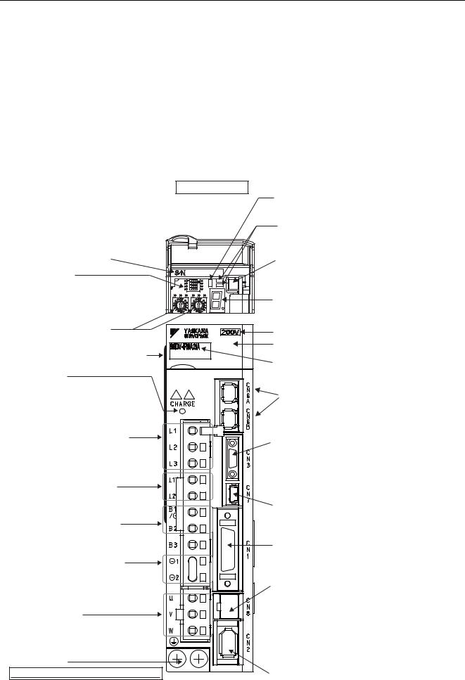
1.2Part Names
This section describes the part names of SGDV SERVOPACK for MECHATROLINK-III communications reference.
|
64 |
|
With front cover open |
|
LED indicator (CN) |
|
Lights when the SERVOPACK normally receives |
|
a CONNECT command. |
|
Communications LED indicators (L1 and L2) |
|
Indicates that data is being transmitted between |
|
the SERVOPACK and the MECHATROLINK system. |
Serial number |
CN5 Analog monitor connector |
DIP switch (S3) |
Used to monitor motor speed, torque reference, |
and other values through a special cable (option). |
|
Used to set MECHATROLINK communications. |
Refer to 5.1.3 Monitoring Operation during Adjustment. |
Refer to 4.1.1 Setting Switches S1, S2, and S3.
|
Panel display |
|
|
Indicates the servo status with a seven-segment |
|
|
LED display. |
|
Rotary switches (S1 and S2) |
Refer to 2.1.1 Status Display. |
|
Input voltage |
||
Used to set MECHATROLINK station address. |
||
Front cover |
||
Refer to 4.1.1 Setting Switches S1, S2, and S3. |
||
Nameplate (Found on side of SERVOPACK.) |
SERVOPACK model |
|
Indicates the SERVOPACK model and ratings. |
||
Charge indicator |
Refer to 1.6 SERVOPACK Model Designation. |
|
|
||
Lights when the main circuit power supply is |
|
|
ON and stays lit as long as the internal |
MECHATROLINK-III communications connectors |
|
capacitor remains charged. Therefore, do not |
||
Connects MECHATROLINK-III-supported devices. |
||
touch the SERVOPACK even after the power |
||
Refer to 3.5 Wiring MECHATROLINK-III Communications. |
||
supply is turned OFF if the indicator is lit. It may |
||
|
||
result in electric shock. |
|
|
Main circuit power supply terminals |
CN3 Connector for digital operator |
|
Used for main circuit power supply input. |
||
Connects a digital operator (option, JUSP-OP05A-1-E) or |
||
Refer to 3.1 Main Circuit Wiring. |
||
a personal computer (RS422). |
||
|
||
|
Refer to Σ-V Series Product Catalog (No. KAEPS 800000 42) |
|
|
and Σ-V Series User’s Manual, Operation of Digital Operator |
|
Control power supply terminals |
(No. SIEP S800000 55). |
|
|
||
Used for control power supply input. |
|
|
Refer to 3.1 Main Circuit Wiring. |
CN7 Connector for personal computer (USB connector) |
|
|
||
|
Communicates with a personal computer. |
|
Regenerative resistor connecting |
Use the connection cable (No: JZSP-CVS06-02-E). |
|
terminals |
|
|
Connects external regenerative resistors. |
CN1 I/O signal connector |
|
Refer to 3.7 Connecting Regenerative Resistors. |
||
|
Used for reference input signals and sequence I/O signals. |
|
DC reactor terminals for harmonic |
Refer to 3.2 I/O Signal Connections. |
|
suppression |
|
|
Connects a DC reactor for harmonic suppression. |
CN8 Connector for safety function devices |
|
Refer to 3.8.3 Connecting a Reactor for Harmonic |
||
Connects a safety function device. |
||
Suppression. |
||
Note: When not using the safety function, use the SERVO- |
||
|
||
Servomotor terminals |
PACK with the safety function’s jumper connector |
|
(JZSP-CVH05-E, provided as an accessory) inserted. |
||
Connects the main circuit cable for servomotor. |
For the connecting method, refer to 3.2.2 Safety Func- |
|
Refer to 3.1 Main Circuit Wiring. |
tion Signal (CN8) Names and Functions. |
|
|
For details on how to use the safety function, refer to |
|
|
4.9 Safety Function. |
|
Ground terminal |
|
|
Be sure to connect to protect against electrical shock. |
CN2 Encoder connector |
|
Refer to 3.1 Main Circuit Wiring. |
||
Connects the encoder in the servomotor. |
||
|
Refer to 3.6 Encoder Connection. |
1-2

1.3 SERVOPACK Ratings and Specifications
1.3SERVOPACK Ratings and Specifications
This section describes the ratings and specifications of SERVOPACKs.
1.3.1Ratings
Ratings of SERVOPACKs are as shown below.
(1) SGDV with Single-phase, 100-V Rating
SGDV (Single Phase, 100 V) |
R70 |
R90 |
2R1 |
2R8 |
Continuous Output Current [Arms] |
0.66 |
0.91 |
2.1 |
2.8 |
|
|
|
|
|
Instantaneous Max. Output Current [Arms] |
2.1 |
2.9 |
6.5 |
9.3 |
|
|
|
|
|
Regenerative Resistor * |
None or external |
|
|
|
|
|
|||
Main Circuit Power Supply |
Single-phase, 100 to 115 VAC –15%+10%, 50/60 Hz |
|||
|
|
|||
Control Power Supply |
Single-phase, 100 to 115 VAC –15%+10%, 50/60 Hz |
|||
|
|
|
|
|
Overvoltage Category |
III |
|
|
|
|
|
|
|
|
Refer to 3.7 Connecting Regenerative Resistors for details.
(2)SGDV with Single-phase, 200-V Rating
|
SGDV (Single Phase, 200 V) |
|
|
|
|
|
|
|
120 *1 |
|
|
|
|
|
|
|
||||
|
Continuous Output Current [Arms] |
|
|
|
|
|
|
|
|
11.6 |
|
|
|
|
|
|
|
|
||
|
|
|
|
|
|
|
|
|
|
|
|
|
|
|
|
|
|
|
|
|
|
Instantaneous Max. Output Current [Arms] |
|
|
|
|
|
|
28 |
|
|
|
|
|
|
|
|
|
|||
|
|
|
|
|
|
|
|
|
|
|
|
|
|
|
|
|
|
|
|
|
|
Regenerative Resistor *2 |
|
|
|
|
Built-in or external |
|
|
|
|
|
|
|
|
|
|
||||
|
Main Circuit Power Supply |
|
|
|
|
Single-phase, 220 to 230 VAC –15%+10%, 50/60 Hz |
|
|
|
|||||||||||
|
|
|
|
|
|
|
|
|
|
|
|
|
|
|
|
|
|
|
||
|
Control Power Supply |
|
|
|
|
Single-phase, 220 to 230 VAC –15%+10%, 50/60 Hz |
|
|
|
|||||||||||
|
|
|
|
|
|
|
|
|
|
|
|
|
|
|
|
|
|
|
|
|
|
Overvoltage Category |
|
|
|
|
III |
|
|
|
|
|
|
|
|
|
|
|
|
|
|
|
|
|
|
|
|
|
|
|
|
|
|
|
|
|
|
|
|
|
|
|
|
1. The official model number is SGDV-120A21A008000. |
|
|
|
|
|
|
|
|
|
|
|
|
|
||||||
|
2. Refer to 3.7 Connecting Regenerative Resistors for details. |
|
|
|
|
|
|
|
|
|
|
|
|
|||||||
(3) SGDV with Three-phase, 200-V Rating |
|
|
|
|
|
|
|
|
|
|
|
|
|
|||||||
|
|
|
|
|
|
|
|
|
|
|
|
|
|
|
|
|
|
|
||
|
SGDV (Three Phase, 200 V) |
R70 |
R90 |
1R6 |
2R8 |
3R8 |
5R5 |
7R6 |
|
120 |
|
180 |
200 |
330 |
470 |
550 |
590 |
780 |
||
|
Continuous Output Current |
0.66 |
0.91 |
1.6 |
2.8 |
|
3.8 |
5.5 |
7.6 |
|
11.6 |
|
18.5 |
19.6 |
32.9 |
46.9 |
54.7 |
58.6 |
78.0 |
|
|
[Arms] |
|
|
|
||||||||||||||||
|
|
|
|
|
|
|
|
|
|
|
|
|
|
|
|
|
|
|
|
|
|
|
|
|
|
|
|
|
|
|
|
|
|
|
|
|
|
|
|
|
|
|
Instantaneous Max. Output |
2.1 |
2.9 |
5.8 |
9.3 |
|
11.0 |
16.9 |
17 |
|
28 |
|
42 |
56 |
84 |
110 |
130 |
140 |
170 |
|
|
Current [Arms] |
|
|
|
||||||||||||||||
|
|
|
|
|
|
|
|
|
|
|
|
|
|
|
|
|
|
|
|
|
|
|
|
|
|
|
|
|
|
|
|
|
|
|
|
|
|
|
|
||
|
Regenerative Resistor * |
None or external |
|
|
Built-in or external |
|
|
|
External |
|
|
|||||||||
|
Main Circuit Power Supply |
Three-phase, 200 to 230 VAC –15%+10%, 50/60 Hz |
|
|
|
|
|
|
|
|
||||||||||
|
|
|
|
|
|
|
|
|
|
|
||||||||||
|
Control Power Supply |
Single-phase, 200 to 230 VAC –15%+10%, 50/60 Hz |
|
|
|
|
|
|
|
|
||||||||||
|
|
|
|
|
|
|
|
|
|
|
|
|
|
|
|
|
|
|
|
|
|
Overvoltage Category |
III |
|
|
|
|
|
|
|
|
|
|
|
|
|
|
|
|
|
|
|
|
|
|
|
|
|
|
|
|
|
|
|
|
|
|
|
|
|
|
|
Refer to 3.7 Connecting Regenerative Resistors for details.
Outline
1
1-3

1 Outline
1.3.1Ratings
(4)SGDV with Three-phase, 400-V Rating
SGDV (Three Phase, 400 V) |
1R9 |
3R5 |
5R4 |
8R4 |
120 |
|
170 |
210 |
|
260 |
280 |
370 |
Continuous Output Current |
1.9 |
3.5 |
5.4 |
8.4 |
11.9 |
|
16.5 |
20.8 |
|
25.7 |
28.1 |
37.2 |
[Arms] |
|
|
||||||||||
|
|
|
|
|
|
|
|
|
|
|
|
|
|
|
|
|
|
|
|
|
|
|
|
|
|
Instantaneous Max. Output |
5.5 |
8.5 |
14 |
20 |
28 |
|
42 |
55 |
|
65 |
70 |
85 |
Current [Arms] |
|
|
||||||||||
|
|
|
|
|
|
|
|
|
|
|
|
|
|
|
|
|
|
|
|
|
|
|
|
|
|
Regenerative Resistor * |
Built-in or external |
|
|
|
|
External |
|
|
|
|||
Main Circuit Power Supply |
Three-phase, 380 to 480 VAC –15%+10%, 50/60 Hz |
|
|
|
|
|
|
|||||
Control Power Supply |
24 VDC ±15% |
|
|
|
|
|
|
|
|
|
|
|
|
|
|
|
|
|
|
|
|
|
|
|
|
Overvoltage Category |
III |
|
|
|
|
|
|
|
|
|
|
|
|
|
|
|
|
|
|
|
|
|
|
|
|
Refer to 3.7 Connecting Regenerative Resistors for details.
1-4

1.3 SERVOPACK Ratings and Specifications
1.3.2Basic Specifications
Basic specifications of SERVOPACKs are shown below.
Drive Method |
|
Sine-wave current drive with PWM control of IGBT |
|||
|
|
|
|
||
Feedback |
|
|
Encoder: 13-bit (incremental), 17-bit, 20-bit (incremental/absolute) |
||
|
|
|
|
|
|
|
Surrounding Air Temper- |
0°C to +55°C |
|
||
|
ature |
|
|
|
|
|
Storage Temperature |
-20°C to +85°C |
|
||
|
|
|
|
||
|
Ambient Humidity |
90% RH or less |
With no freezing or condensation |
||
|
|
|
|
||
|
Storage Humidity |
90% RH or less |
|||
|
|
||||
|
|
|
|
||
|
Vibration Resistance |
4.9 m/s2 |
|
||
Operating |
Shock Resistance |
19.6 m/s2 |
|
||
Conditions |
|
|
|
|
|
Protection Class |
IP10 |
An environment that satisfies the following conditions. |
|||
|
|||||
|
|
|
|
• Free of corrosive or flammable gases |
|
|
|
|
|
• Free of exposure to water, oil, or chemicals |
|
|
Pollution Degree |
2 |
|||
|
• Free of dust, salts, or iron dust |
||||
|
|
|
|
|
|
|
Altitude |
|
1000 m or less |
|
|
|
|
|
|
||
|
Others |
|
Free of static electricity, strong electromagnetic fields, magnetic fields or |
||
|
|
exposure to radioactivity |
|||
|
|
|
|||
|
|
|
|
|
|
Harmonized Standards |
|
UL508C |
|
||
|
EN50178, EN55011 group1 class A, EN61000-6-2, EN61800-3, EN61800- |
||||
|
|
|
5-1, EN954-1, IEC61508-1 to 4 |
||
|
|
|
|
||
Mounting |
|
|
Standard: Base-mounted |
||
|
|
Optional: Rack-mounted or duct-ventilated |
|||
|
|
|
|||
|
|
|
|
|
|
|
Speed Control Range |
1:5000 (The lower limit of the speed control range must be lower than the |
|||
|
point at which the rated torque does not cause the servomotor to stop.) |
||||
|
|
|
|||
|
|
|
|
|
|
|
|
Load |
0% to 100% load: ±0.01% max. (at rated speed) |
||
|
|
Regulation |
|||
|
Speed |
|
|
||
|
|
|
|
||
|
Voltage |
|
|
||
|
Regu- |
Rated voltage ±10%: 0% (at rated speed) |
|||
|
Regulation |
||||
Perfor- |
lation*1 |
|
|
||
|
|
|
|||
Temperature |
25 ± 25 °C: ±0.1% max. (at rated speed) |
||||
mance |
|
||||
|
|
Regulation |
|
|
|
|
Torque Control |
±1% |
|
||
|
Tolerance |
|
|
||
|
(Repeatability) |
|
|
||
|
|
|
|
||
|
Soft Start Time |
0 to 10 s (Can be set individually for acceleration and deceleration.) |
|||
|
Setting |
|
|||
|
|
|
|
||
|
|
|
|
|
|
Outline
1
1-5

1 Outline
1.3.2 Basic Specifications
(cont’d)
|
Encoder Output Pulse |
Phase A, B, C: line driver |
|||
|
Encoder output pulse: any setting ratio (Refer to 4.4.5.) |
||||
|
|
|
|||
|
|
|
|
|
|
|
|
|
Number of |
7 ch |
|
|
|
|
Channels |
||
|
|
|
|
||
|
|
|
|
|
|
|
|
Input |
|
• Homing deceleration switch (/DEC) |
|
|
|
|
• External latch (/EXT 1 to 3) |
||
|
Sequence |
Signals |
|
• Forward run prohibited (P-OT), reverse run prohibited |
|
|
Input |
which can |
Functions |
(N-OT) |
|
|
|
be allocated |
• Forward external torque limit (/P-CL), reverse external |
||
|
|
|
|
torque limit (/N-CL) |
|
|
|
|
|
Signal allocations can be performed, and positive and |
|
|
|
|
|
negative logic can be changed. |
|
I/O |
|
|
|
|
|
|
Fixed Output |
Servo alarm (ALM) |
output |
||
Signals |
|
|
|
|
|
|
|
Number of |
3 ch |
||
|
|
|
|||
|
|
|
Channels |
||
|
|
|
|
||
|
|
|
|
|
|
|
|
|
|
• Positioning completion (/COIN) |
|
|
|
|
|
• Speed coincidence detection (/V-CMP) |
|
|
Sequence |
Output |
|
• Rotation detection (/TGON) |
|
|
|
• Servo ready (/S-RDY) |
|||
|
Output |
Signals |
|
||
|
|
• Torque limit detection (/CLT) |
|||
|
|
which can |
Functions |
||
|
|
• Speed limit detection (/VLT) |
|||
|
|
be allocated |
|||
|
|
|
|
• Brake (/BK) |
|
|
|
|
|
• Warning (/WARN) |
|
|
|
|
|
• Near (/NEAR) |
|
|
|
|
|
Signal allocations can be performed, and positive and |
|
|
|
|
|
negative logic can be changed. |
|
|
|
|
|
|
|
|
|
Interface |
Digital operator (JUSP-OP05A-1-E), personal computer (can be connected |
||
|
|
with SigmaWin+) |
|
||
|
|
|
|
||
|
RS422A |
|
|
|
|
|
1:N |
|
|
||
|
Commu- |
Communica- |
N = Up to 15 stations possible at RS422A |
||
|
nications |
tions |
|
|
|
Communi- |
(CN3) |
|
|
|
|
Axis |
|
|
|||
cations |
|
|
|
||
|
Address |
Set by parameter |
|
||
Function |
|
|
|||
|
Setting |
|
|
||
|
|
|
|
||
|
|
|
|
||
|
USB |
Interface |
Personal computer (can be connected with SigmaWin+) |
||
|
Commu- |
|
|
|
|
|
Communica- |
|
|
||
|
nications |
tions |
Complies with standard USB1.1. (12 Mbps) |
||
|
(CN7) |
Standard |
|
|
|
|
|
|
|
||
LED Display |
|
|
Panel display (seven-segment), CHARGE, L1, L2, and CN indicators |
||
|
|
|
|
|
|
MECHATROLINK-III |
|
Rotary Switch |
Position: 16 positions × 2 (Refer to 4.1.1) |
||
|
(S1, S2) |
||||
Communications Setting Switches |
|
|
|||
DIP Switch (S3) |
Number of pins: Four pins (Refer to 4.1.1) |
||||
|
|
|
|||
|
|
|
|
|
|
|
|
|
Number of points: |
2 |
|
|
|
|
Output voltage: ± 10VDC (linearity effective range ± 8 V) |
||
Analog Monitor (CN5) |
|
Resolution: 16 bits |
|
||
|
Accuracy: ± 20 mV (Typ) |
||||
|
|
|
|||
|
|
|
Max. output current: ± 10 mA |
||
|
|
|
Settling time (± 1%): 1.2 ms (Typ) |
||
|
|
|
|
||
Dynamic Brake (DB) |
|
Activated when a servo alarm or overtravelling occurs or when the power |
|||
|
supply for the main circuit or servomotor is OFF. |
||||
|
|
|
|||
|
|
|
|||
Regenerative Processing |
Included *2 |
|
|||
Overtravel Prevention (OT) |
Dynamic brake stop, deceleration to a stop, or free run to a stop at P-OT or |
||||
N-OT |
|
||||
|
|
|
|
||
|
|
|
|
||
Protective Function |
|
Overcurrent, overvoltage, insufficient voltage, overload, regeneration error, |
|||
|
and so on. |
|
|||
|
|
|
|
||
|
|
|
|||
Utility Function |
|
Gain adjustment, alarm history, JOG operation, origin search, and so on. |
|||
|
|
|
|
|
|
1-6

1.3 SERVOPACK Ratings and Specifications
(cont’d)
|
Input |
/HWBB1, /HWBB2: Baseblock signal for power module |
|
|
|
Safety Function |
Output |
EDM1: Monitoring status of internal safety circuit (fixed output) |
|
|
|
|
Standards *3 |
EN954 Category 3, IEC61508 SIL2 |
Option Module |
|
Fully-closed module, safety module |
|
|
|
1. Speed regulation by load regulation is defined as follows:
|
Speed regulation = |
- Total load motor speed |
× 100% |
Rotation |
|
|
|
No-load motor speed |
|
|
|
2. |
|
Rated |
motor speed |
|
|
Refer to 1.3.1 Ratings for details on regenerative resistors. |
|
|
|||
3. |
Perform risk assessment for the system and be sure that the safety requirements are fulfilled. |
||||
Outline
1
1-7

1 Outline
1.3.3MECHATROLINK-III Function Specifications
1.3.3MECHATROLINK-III Function Specifications
The following table shows the specifications of MECHATROLINK-III.
|
Function |
Specifications |
||
|
|
Communication Pro- |
MECHATROLINK-III |
|
|
|
tocol |
||
|
|
|
||
|
|
|
|
|
|
|
Station Address |
03H to EFH (Max. number of stations: 62) |
|
|
|
Use the rotary switches S1 and S2 to set the station address. |
||
MECHATROLINK-III |
|
|||
|
|
|||
Baud Rate |
100 Mpbs |
|||
Communication |
|
|||
|
|
|
||
|
|
Transmission Cycle |
125 μs, 250 μs, 500 μs, 750 μs, and 1.0 ms to 4.0 ms (incre- |
|
|
|
ments of 0.5 ms) |
||
|
|
|
||
|
|
|
|
|
|
|
Number of Transmis- |
16, 32, or 48 bytes per station |
|
|
|
sion Bytes |
Use the DIP switch S3 to select the number of words. |
|
|
|
|
|
|
|
|
Control Method |
Position, speed, or torque control with MECHATROLINK- |
|
|
|
III communication |
||
|
|
|
||
|
|
|
|
|
Reference Method |
|
Reference Input |
MECHATROLINK commands (sequence, motion, data set- |
|
|
ting/reference, monitoring, or adjustment) |
|||
|
|
|
||
|
|
|
|
|
|
|
Profile |
MECHATROLINK-III standard servo profile |
|
|
|
MECHATROLINK-II-compatible profile |
||
|
|
|
||
|
|
|
|
|
1-8

1.4 SERVOPACK Internal Block Diagrams
1.4SERVOPACK Internal Block Diagrams
1.4.1Single-phase 100 V, SGDV-R70F21A, -R90F21A, -2R1F21A Models
M-III
|
|
|
B1/ |
B2 |
Fan |
|
|
|
|
|
|
+12 V |
Servomotor |
|
L1 |
Varistor |
|
|
|
|
|
|
|
U |
|
||
Main circuit |
L2 |
+ |
|
|
V |
|
– |
|
|
|
|||
power supply |
|
|
|
|||
|
+ |
CHARGE |
|
W |
M |
|
|
|
– |
|
|||
|
|
|
|
|
|
Dynamic brake circuit
Voltage |
Relay |
Voltage |
Gate |
Temperature |
Gate drive |
Current |
overcurrent |
||||||
sensor |
drive |
sensor |
drive |
sensor |
protector |
sensor |
ENC
|
|
|
|
|
|
|
CN2 |
|
L1C Varistor |
|
Control |
±12 V |
|
Analog |
CN5 |
|
|
+ |
+5 V |
|
|
||
Control power |
|
ASIC |
voltage |
|
|||
L2C |
– |
power |
+17 V |
converter |
CN1 |
||
supply |
|
supply |
(PWM control, etc.) |
|
|||
|
|
|
|
|
|||
|
|
|
|
|
CPU |
I/O |
CN6A |
|
|
|
|
|
|
||
|
|
|
Panel display |
|
(Position/speed |
|
|
|
|
|
|
calculation, etc.) |
I/F |
|
|
|
|
|
|
|
|
CN3 |
CN7 |
CN6B |
CN8 |
||
Digital operator |
Personal |
Signal for safety fuction |
|
computer |
|
Analog monitor output
Encoder output pulse
I/O signal
MECHATROLINK-III communications
1.4.2Single-phase 100 V, SGDV-2R8F21A Model
|
|
|
B1/ |
B2 |
Fan |
M-III |
|
|
|
|
|||
|
|
|
|
|
|
Servomotor |
|
L1 Varistor |
|
|
|
+12 V |
|
Main circuit |
|
|
|
U |
|
|
|
+ |
|
|
V |
|
|
power supply |
L2 |
– |
|
|
|
|
+ |
|
|
M |
|||
|
|
|
|
|||
|
|
– |
CHARGE |
|
W |
|
|
|
|
|
|
|
Dynamic brake circuit
Voltage |
Relay |
Voltage |
Gate |
Gate drive |
Temperature |
Current |
overcurrent |
||||||
sensor |
drive |
sensor |
drive |
protector |
sensor |
sensor |
ENC
|
|
|
|
|
|
|
CN2 |
|
L1C Varistor |
|
Control |
±12 V |
|
Analog |
CN5 |
Control power |
|
+ |
+5 V |
|
|
||
|
power |
ASIC |
voltage |
|
|||
L2C |
– |
|
converter |
CN1 |
|||
supply |
supply |
+17 V |
(PWM control, etc.) |
|
|||
|
|
||||||
|
|
|
|
|
CPU |
I/O |
CN6A |
|
|
|
|
|
|
||
|
|
|
Panel display |
|
(Position/speed |
|
|
|
|
|
|
calculation, etc.) |
I/F |
|
|
|
|
|
|
|
|
CN3 |
CN7 |
CN6B |
CN8 |
||
Digital operator |
Personal |
Signal for safety fuction |
|
computer |
|
Analog monitor output
Encoder output pulse
I/O signal
MECHATROLINK-III communications
Outline
1
1-9
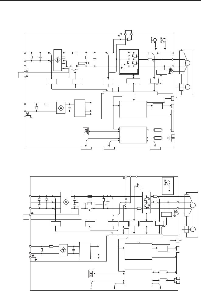
1 Outline
1.4.3Single-phase 200 V, SGDV-120A21A008000 Model
1.4.3Single-phase 200 V, SGDV-120A21A008000 Model
|
|
|
|
|
|
|
|
|
|
|
|
64 |
|
|
|
|
|
B1/ |
B2 |
B3 |
Fan 1 |
Fan 2 |
|
|
|
|
|
|
|
|
|
|
|
|
|
|
|
Servomotor |
Main circuit |
L1Varistor |
|
|
|
|
|
|
±12 V |
|
±12 V |
U |
|
|
|
|
|
|
|
|
|
|
|
V |
|
|
power supply |
L2 |
|
|
+ |
|
|
|
|
|
|
|
|
|
|
– |
|
|
|
|
|
|
M |
|||
|
|
|
|
|
|
|
|
|
|
|
||
|
L3 |
|
CHARGE |
|
|
|
|
|
|
|
W |
|
|
|
|
|
|
|
|
|
|
|
|
||
|
1 |
|
|
|
|
Overheat protector, |
Dynamic |
|
|
|||
|
2 |
|
|
|
|
overcurrent protector |
brake circuit |
|
|
|||
|
|
|
|
|
|
|
|
|
|
|
|
|
|
Voltage |
|
Relay |
|
Voltage |
|
Gate drive |
Current |
|
|
|
|
|
sensor |
|
drive |
|
sensor |
|
|
sensor |
|
|
|
|
|
|
|
|
|
|
|
|
|
|
|
|
ENC |
|
|
|
|
|
|
|
|
|
|
CN2 |
|
|
|
L1C Varistor |
|
Control |
+15V × 4 |
|
|
|
Analog |
|
CN5 |
Analog monitor |
|
Control power |
|
+ |
|
|
|
|
|
|
|
|||
|
power |
|
|
|
ASIC |
voltage |
|
|
|
|||
L2C |
– |
|
|
|
converter |
CN1 |
output |
|||||
supply |
supply |
+5 V |
|
(PWM control, etc.) |
|
|
|
|||||
|
|
|
|
|
||||||||
|
|
|
|
|
|
|
|
|||||
|
|
|
|
±12 V |
|
|
|
|
|
|
|
Encoder output |
|
|
|
|
|
|
|
|
|
|
|
|
|
|
|
|
|
|
|
|
|
|
|
|
|
pulse |
|
|
|
|
|
|
|
CPU |
I/O |
|
CN6A |
I/O signal |
|
|
|
|
|
|
|
|
|
|
MECHATROLINK-III |
|||
|
|
|
Panel display |
|
|
(Position/speed |
|
|
|
|
||
|
|
|
|
calculation, etc.) |
I/F |
|
|
|
communications |
|||
|
|
|
|
|
|
|
|
|
||||
|
|
|
|
CN3 |
CN7 |
|
|
|
|
CN6B |
|
|
|
|
|
|
|
|
CN8 |
|
|
||||
Digital operator |
Personal |
Signal for safety fuction |
|
computer |
|
1.4.4 Three-phase 200 V, SGDV-R70A21 , -R90A21 , -1R6A21 Models
L1 Varistor
Main circuit  L2
L2
power supply
L3
CHARGE 


B1/ B2 B3 |
M-III |
Fan * |
Servomotor
+12 V
U
+ |
V |
–
W M
1 |
Dynamic |
|
brake circuit |
 2
2
Voltage |
Relay |
Voltage |
Gate |
Temperature |
Gate drive |
Current |
overcurrent |
sensor |
|||||
sensor |
drive |
sensor |
drive |
sensor |
protector |
|
|
|
|
|
|
|
ENC |
|
|
|
|
|
|
|
CN2 |
Control power |
L1C |
Varistor |
+ |
Control |
+17 V |
Analog |
CN5 |
|
|
power |
ASIC |
voltage |
|
||
L2C |
|
– |
converter |
CN1 |
|||
supply |
|
|
supply |
(PWM control, etc.) |
|
||
|
|
|
|
|
+5 V |
|
|
|
|
|
|
|
±12 V |
|
|
|
|
|
|
|
CPU |
I/O |
CN6A |
|
|
|
|
|
|
||
|
|
|
|
Panel display |
(Position/speed |
|
|
|
|
|
|
calculation, etc.) |
I/F |
|
|
|
|
|
|
|
|
|
CN3 |
CN7 |
|
|
|
CN6B |
||
|
|
|
CN8 |
|||||
|
|
|
|
|
|
|
|
|
|
Digital operator |
Personal |
|
Signal for safety fuction |
||||
|
|
|
computer |
|
|
|
|
|
The following SERVOPACKs do not have cooling fans: SGDV- |
B. |
|||||||
Analog monitor output
Encoder output pulse
I/O signal
MECHATROLINK-III communications
1-10
Loading...