


 Loading...
MotionWorks IEC
PLCopenPlus Function Blocks for Motion Control - 2013-04-12

Table Of Contents |
|
Overview.................................................................................... |
1 |
Introduction ............................................................................. |
1 |
The State Diagram.................................................................... |
3 |
Error Handling.......................................................................... |
6 |
Function block interface............................................................. |
8 |
Data Types ................................................................................ |
29 |
Data Types ............................................................................. |
29 |
Data Type: AXIS_REF............................................................... |
30 |
Data Type: CONTINUOUS_REF .................................................. |
32 |
Data Type: INPUT_REF............................................................. |
34 |
Data Type: OUTPUT_REF .......................................................... |
36 |
Data Type: PATTERN_REF......................................................... |
38 |
Data Type: PrmStruct .............................................................. |
39 |
Data Type: RTC_STRUCT .......................................................... |
40 |
Data Type: TRIGGER_REF......................................................... |
41 |
Data Type: Y_DISENGAGE_DATA............................................... |
43 |
Data Type: Y_ENGAGE_DATA.................................................... |
44 |
Data Type: Y_MS_CAM_STRUCT................................................ |
45 |
iii

Enumerated Types...................................................................... |
47 |
Function Block List...................................................................... |
49 |
Function Block List ................................................................... |
49 |
Function Blocks for Motion Control................................................ |
61 |
MC_AbortTrigger ..................................................................... |
61 |
MC_FinishHoming .................................................................... |
65 |
MC_GearIn ............................................................................. |
68 |
MC_GearInPos......................................................................... |
74 |
MC_GearOut ........................................................................... |
83 |
MC_MoveAbsolute.................................................................... |
86 |
MC_MoveRelative..................................................................... |
92 |
MC_MoveSuperImposed ........................................................... |
97 |
MC_MoveVelocity................................................................... |
109 |
MC_Power............................................................................. |
114 |
MC_ReadActualPosition........................................................... |
121 |
MC_ReadActualTorque............................................................ |
123 |
MC_ReadActualVelocity .......................................................... |
126 |
MC_ReadAxisError ................................................................. |
128 |
MC_ReadBoolParameter.......................................................... |
132 |
iv

MC_ReadParameter................................................................ |
135 |
MC_ReadStatus ..................................................................... |
138 |
MC_Reset ............................................................................. |
142 |
MC_SetPosition...................................................................... |
146 |
MC_StepLimitSwitch............................................................... |
150 |
MC_StepRefPulse................................................................... |
155 |
MC_Stop............................................................................... |
160 |
MC_TorqueControl ................................................................. |
165 |
MC_TouchProbe..................................................................... |
176 |
MC_WriteBoolParameter ......................................................... |
185 |
MC_WriteParameter ............................................................... |
188 |
Y_CamFileSelect .................................................................... |
191 |
Y_CamIn .............................................................................. |
197 |
Y_CamOut ............................................................................ |
210 |
Y_CamScale.......................................................................... |
215 |
Y_CamShift........................................................................... |
220 |
Y_CamStructSelect ................................................................ |
227 |
Y_ClearAlarms....................................................................... |
231 |
Y_DirectControl ..................................................................... |
233 |
v

Y_HoldPosition ...................................................................... |
239 |
Y_ProbeContinuous ................................................................ |
242 |
Y_ReadAlarm ........................................................................ |
248 |
Y_ReadCamTable................................................................... |
250 |
Y_ReadDriveParameter........................................................... |
254 |
Y_ReadMultipleParameters...................................................... |
258 |
Y_ReadStringParameter.......................................................... |
261 |
Y_RebootController ................................................................ |
264 |
Y_ReleaseCamTable ............................................................... |
266 |
Y_ResetAbsoluteEncoder......................................................... |
268 |
Y_ResetMechatrolink .............................................................. |
273 |
Y_SetRTC ............................................................................. |
276 |
Y_SlaveOffset........................................................................ |
278 |
Y_VerifyParameters................................................................ |
285 |
Y_WriteCamTable .................................................................. |
290 |
Y_WriteDriveParameter .......................................................... |
293 |
Y_WriteParameters ................................................................ |
297 |
Controller AlarmID List.............................................................. |
301 |
Function Block ErrorID List ........................................................ |
333 |
vi

Axis Parameter List................................................................... |
341 |
High Speed Output ................................................................... |
349 |
Timing Diagram........................................................................ |
350 |
Camming................................................................................. |
353 |
Camming Introduction............................................................ |
353 |
CamState ............................................................................. |
353 |
Cam Masters ......................................................................... |
355 |
Master Cycle ......................................................................... |
355 |
Camming Function Blocks ....................................................... |
356 |
Creating a Cam Table............................................................. |
357 |
Externally Created Cam Data .................................................. |
358 |
Transferring Cam Files to an MPiec Controller............................ |
359 |
User File Storage ................................................................... |
362 |
Configuring FileName Input for Y_CamFileSelect........................ |
363 |
Internally Created Cam Data................................................... |
365 |
Cam Table Types ................................................................... |
367 |
On-The-Fly Adjustments ......................................................... |
368 |
Camming Block Diagram......................................................... |
369 |
Engage / Disengage Window ................................................... |
370 |
vii

Cam Transitions Matrix........................................................... |
371 |
Motion Details .......................................................................... |
375 |
Acceleration/Deceleration Limits .............................................. |
375 |
Position Limits....................................................................... |
377 |
Velocity Limits....................................................................... |
379 |
Moving Average Filter (S-Curve).............................................. |
380 |
Determining When Motion is Complete ..................................... |
383 |
External Encoder Block Diagram .............................................. |
385 |
Commanded Position Output ................................................... |
386 |
Command Filtering (MPiec with MECHATROLINK interface).......... |
387 |
Command Filtering (MP2600iec - Dual Port RAM interface).......... |
388 |
viii

Overview
This document contains instructions for using the PLCopenPlus and YMotion firmware library function blocks integrated in the MPiec Series Controllers.
Introduction
This manual is adopted from the PLCopen for motion control specification at www.plcopen.org, and includes additional information for functionality with Yaskawa and other components.
Each function block is listed in alphabetical order, and is also linked to the feature or function from the software environment. A comprehensive list of axis parameters and error codes is at the back of the manual. A subset of specific errors that each function block may generate is included under each function block description.
The other main concepts covered in this manual are the Motion State Diagram, and documentation concerning the Data Types supplied with the PLCopenPlus Firmware Library.
The Firmware Library is the set of all PLCopen function blocks, plus Yaskawa specific functions. The firmware library is called PLCopen Plus, and is automatically loaded when a new project is created.
Model
The PLCopenPlus Function Block (FB) library is designed for the purpose of controlling axes via the language elements consistent with those defined in the IEC 61131-3 standard. It provides a set of command oriented function
PLCopenPlus Function Blocks for Motion Control 2013-04-13 |
1 |

blocks that have a reference to the axis, e.g. the abstract data type ‘Axis’, which offers flexibility, ease of use and reusability.
PLCopenPlus Function Blocks for Motion Control 2013-04-13 |
2 |
The State Diagram
The state diagram shown defines the behavior of the axis at a high level when motion control function blocks are "simultaneously" activated. This combination of motion profiles is useful in building a more complicated profile or to treat exceptions within a program.
The basic rule is that motion commands are always taken sequentially. These commands act on the axis' state diagram. The axis is always in one of the following defined states:
Standstill (no movement)
Homing (movement to reference position)
Discrete Motion (movement towards target position)
Continuous Motion (jogging)
Synchronized Motion (synchronized movement of master and slave)
Stopping (axis is stopped)
ErrorStop (axis error occurred)
Any motion command is a transition that changes the state of the axis and, as a consequence, modifies the way the current motion is computed. A normal procedure would start in Standstill. In this state, the power can be switched on per axis (via the Power command). Also, one can access the Homing state (via the issue of the Home command per axis), which after normal completion returns to Standstill. From here, one can transfer an axis to either Discrete Motion or Continuous Motion. Via the Stopping state, one can return to Standstill. ErrorStop is a state to which the axis transfers in case of an error. Via a Reset command, one can return to Standstill, from which the machine can be moved to an operational state again. Please note that the states define the functionality of the Function Blocks.
PLCopenPlus Function Blocks for Motion Control 2013-04-13 |
3 |

The diagram is focused on the states of a single axis. The multiple axis function blocks such as MC_CamIn and MC_GearIn change the state whereas these axis can have specific states.
Connecting a slave axis to a master axis has no influence on the master axis.
PLCopenPlus Function Blocks for Motion Control 2013-04-13 |
4 |

PLCopenPlus Function Blocks for Motion Control 2013-04-13 |
5 |

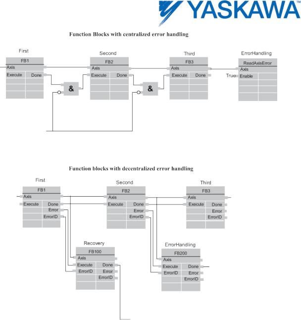
Error Handling
All access to the drive/motion control is via Function Blocks. Internally these Function Blocks provide basic error checking on the input data.
If the device itself has an error, it can be read using the MC_ReadAxisError block.
PLCopenPlus Function Blocks for Motion Control 2013-04-13 |
6 |
PLCopenPlus Function Blocks for Motion Control 2013-04-13 |
7 |

Function block interface
General rules
The following table provides general rules about the interface of the Motion Control function blocks.
Rule applies to |
Rule |
|
|
||
Output exclusivity |
When 'Execute' is true, the outputs ‘Busy’, |
|
|
‘Done’, ‘Error’, and ‘CommandAborted’ are |
|
|
mutually exclusive. |
|
|
|
|
Output status |
The 'Done', 'InGear', 'InSync', 'InVelocity', |
|
|
'Error', 'ErrorID' and 'CommandAborted' outputs |
|
|
are reset with the falling edge of |
|
|
'Execute'. However, the falling edge of 'Execute' |
|
|
does not stop or even influence the execution of |
|
|
the actual FB. The corresponding outputs are |
|
|
set for at least one cycle if the situation occurs, |
|
|
even if execute was reset before the FB |
|
|
completed. If an instance of a FB receives a |
|
|
new 'Execute' before it finishes (as a series of |
|
|
commands on the same instance), the FB won’t |
|
|
return any feedback, like ‘Done’ or |
|
|
‘CommandAborted’, for the previous action. |
|
|
|
|
Input parameters |
The parameters are read at the rising edge of |
|
|
the 'Execute' input. To modify any parameter, it |
|
|
is necessary to change the input parameter(s) |
|
|
and trigger the 'Execute' again. |
|
|
|
|
Missing input |
According to IEC 61131-3, if any parameter of a |
|
parameters |
function block input is missing (“open”) then the |
|
|
|
|
PLCopenPlus Function Blocks for Motion Control 2013-04-13 |
8 |
|

|
value from the previous invocation of this |
|
instance will be used. In the first invocation the |
|
default value is applied. |
|
|
Position versus |
'Position' is a value defined within a coordinate |
distance |
system. 'Distance' is a relative measure, the |
|
difference between two positions. |
|
|
Sign rules |
The 'Velocity', 'Acceleration', 'Deceleration' and |
|
'Jerk' are always positive values. 'Position' and |
|
'Distance' can be positive or negative. |
|
|
Error Handling |
All blocks have two outputs, which deal with |
Behavior |
errors that can occur while executing that |
|
Function Block. These outputs are defined as |
|
follow: |
|
|
|
Error: Rising edge of 'Error' indicates that an |
|
error occurred during the execution of the |
|
Function Block. |
|
ErrorID: Error number - see the Error Code List |
|
at the end of the manual. |
|
|
|
'Done', 'InVelocity', 'InGear', and 'InSync' |
|
indicate successful completion, so these signals |
|
are logically exclusive to “Error”. |
|
Types of errors: |
|
• Function Block Error (e.g. parameters out of |
|
range, state machine violation attempted) |
|
• Communication Error |
|
• Amplifier/Axis Error |
|
Instance errors do not always result in an axis |
|
error (forcing the axis to 'StandStill'). The error |
|
outputs of the relevant FB are reset with falling |
|
|
PLCopenPlus Function Blocks for Motion Control 2013-04-13 |
9 |

|
edge of 'Execute'. |
|
|
|
|
Behavior of Done |
The “Done” output (as well as 'InGear', |
|
output |
'InSync', ..) is set when the commanded action |
|
|
has been completed successfully. With multiple |
|
|
Function Blocks working on the same axis in a |
|
|
sequence, the following applies: |
|
|
When one movement on an axis is interrupted |
|
|
with another movement on the same axis |
|
|
without having reached the final goal, 'Done' of |
|
|
the first FB will not be set. |
|
|
|
|
Behavior of |
'CommandAborted' is set when a commanded |
|
CommandAborted |
motion is interrupted by another motion |
|
output |
command. The reset-behavior of |
|
|
'CommandAborted' is like that of 'Done'. When |
|
|
'CommandAborted' occurs, the other output- |
|
|
signals such as 'InVelocity' are reset. |
|
|
|
|
Inputs exceeding |
If a FB is commanded with parameters which |
|
application limits |
result in a violation of application limits, the |
|
|
instance of the FB generates an error. The |
|
|
consequences of this error for the axis are |
|
|
application specific and thus should be handled |
|
|
by the application program. |
|
|
|
|
Behavior of Busy |
'Busy' output indicates that the FB is not |
|
output |
finished. 'Busy' is SET at the rising edge of |
|
|
'Execute' and RESET when one of the outputs |
|
|
'Done', 'Aborted', or 'Error' is set. It is |
|
|
recommended that this FB should be kept in the |
|
|
active loop of the application program for at |
|
|
least as long as ‘Busy’ is true, because the |
|
|
|
|
PLCopenPlus Function Blocks for Motion Control 2013-04-13 |
10 |
|

|
outputs may still change. For one axis, several |
|
Function Blocks might be busy, but only one can |
|
be active at a time. Exceptions are |
|
'MC_SuperImposed' and 'MC_Phasing', where |
|
more than one FB related to one axis can be |
|
active. |
|
|
Output ‘Active’ |
The 'Active' output is available on Function |
|
Blocks with buffering capabilities. This output is |
|
set at the moment the function block takes |
|
control of the axis. For unbuffered mode the |
|
outputs “Active” and “Busy” can have the same |
|
value. |
|
|
Enable and Valid |
The 'Enable' input is coupled to a 'Valid' output. |
Status |
'Enable' is level sensitive, and 'Valid' shows that |
|
a valid set of outputs is available at the FB. The |
|
'Valid' output is TRUE as long as a valid output |
|
value is available and the 'Enable' input is |
|
TRUE. The relevant output values are refreshed |
|
while the input 'Enable' is TRUE. If there is a FB |
|
error, the output is not valid (“Valid” set to |
|
FALSE). When the error condition disappears, |
|
the values will reappear and 'Valid' output will |
|
be set again. |
|
|
PLCopenPlus Function Blocks for Motion Control 2013-04-13 |
11 |
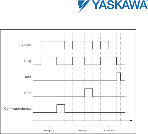
The behavior of the “Execute” / “Done” style FBs is as follows:
Why the command input is edge sensitive
The “Execute” input always triggers the function with its rising edge. New input values may be commanded during execution of a previous command because the inputs are only read once. The 'Done' output can be used to trigger the next part of the movement. The example given below is intended to explain the behavior of the Function Block execution.
PLCopenPlus Function Blocks for Motion Control 2013-04-13 |
12 |
The figure illustrates the sequence of three Function Blocks, 'First', 'Second' and 'Third', controlling the same axis. These three Function Blocks could be for instance various absolute or relative move commands. When “First” has completed, the output 'First.Done' triggers 'Second.Execute'. The output 'Second.Done' AND “In13” trigger 'Third.Execute'.
PLCopenPlus Function Blocks for Motion Control 2013-04-13 |
13 |

Example 1: Same Function Block instance controls different motions of an axis
The figure below shows an example where the Function Block FB1 is used to control “AxisX” with three different values of Velocity. In a Sequential Function Chart (SFC) the velocity 10, 20, and 0 is assigned to V. To trigger the Execute input with a rising edge the variable E is stepwise set and reset.
PLCopenPlus Function Blocks for Motion Control 2013-04-13 |
14 |

PLCopenPlus Function Blocks for Motion Control 2013-04-13 |
15 |

Example 2: Different FB instances control the motions of an axis
Different instances related to the same axis can control the motions on an axis. Each instance will then be responsible for one part of the global profile.
PLCopenPlus Function Blocks for Motion Control 2013-04-13 |
16 |

PLCopenPlus Function Blocks for Motion Control 2013-04-13 |
17 |

Aborting Versus Buffered Modes: Input BufferMode
Some of the FBs provide the input 'BufferMode'. By setting this input, the FB can either be run in "non-buffered mode" (default behavior) or in buffered mode. The transition behavior (blending) between two motions can be set by defining when the FB starts its action. The difference between these two modes is as follows:
A Function Block in non-buffered mode is applied immediately, even when this interrupts a motion which is currently executed.
A Function Block in buffered mode is not executed until the current FB has finished the motion it is currently executing and indicates this by setting the corresponding output (Done or InPosition or InVelocity - see table below).
Up to 16 motion blocks can be buffered before error 4369 would be generated. Axis Parameter 1600 indicates the number of buffered motion blocks.
Possible options for the buffered mode
The input BufferMode must be connected with a INT data type which can have the following values:
Buffer mode |
Short description Important |
|
Input value at |
|
|||
|
note: The meaning of each value |
|
BufferMode * |
|
may vary depending on the |
|
|
|
FB(s) involved. For this reason, |
|
|
|
please also refer to the |
|
|
|
individual parameter |
|
|
|
descriptions! |
|
|
Aborting |
This is the Default mode. The FB |
|
INT#0 |
|
aborts an ongoing motion and the |
|
|
|
command affects the axis |
|
|
|
immediately. |
|
|
Buffered |
The FB affects the axis as soon as |
|
INT#1 |
|
the previous movement is |
|
|
|
complete. The axis will stop |
|
|
|
between the movements. |
|
|
BlendingLow |
The FB controls the axis after the |
|
INT#2 |
PLCopenPlus Function Blocks for Motion Control 2013-04-13 |
18 |
||

|
previous FB has finished, but the |
|
|
axis will not stop between the |
|
|
movements. The velocity is blended |
|
|
with the lowest velocity of both |
|
|
commands. |
|
BlendingPrevious |
The FB controls the axis after the |
INT#3 |
|
previous FB has finished |
|
|
(equivalent to buffered), but the |
|
|
axis will not stop between the |
|
|
movements. Blending with the |
|
|
velocity of the previous move. |
|
BlendingNext |
The FB controls the axis after the |
INT#4 |
|
previous FB has finished, but the |
|
|
axis will not stop between the |
|
|
movements. Blending with velocity |
|
|
of this (next) function. |
|
BlendingHigh |
The FB controls the axis after the |
INT#5 |
|
previous FB has finished |
|
|
(equivalent to buffered), but the |
|
|
axis will not stop between the |
|
|
movements. Blending with highest |
|
|
velocity of the previous and this |
|
|
(next) function. |
|
PLCopenPlus Function Blocks for Motion Control 2013-04-13 |
19 |

Example 1: Standard behavior of 2 following absolute movements
PLCopenPlus Function Blocks for Motion Control 2013-04-13 |
20 |

Example 2: Aborting motion
PLCopenPlus Function Blocks for Motion Control 2013-04-13 |
21 |

Example 3: Buffered motion
PLCopenPlus Function Blocks for Motion Control 2013-04-13 |
22 |
Loading...