


 Loading...
E7 Drive
User Manual
|
|
|
|
|
|
|
|
|
|
Model: E7U |
Document Number: TM.E7.01 |
|||
|
|
|
|
|
Quick Reference for E7 Parameters
Parameter |
Factory |
User |
Parameter |
Factory |
User |
Parameter |
Factory |
User |
Parameter |
Factory |
User |
Number |
Setting |
Setting |
Number |
Setting |
Setting |
Number |
Setting |
Setting |
Number |
Setting |
Setting |
A1-00 |
0 |
|
b5-07 |
0 |
|
E1-07 |
3 |
|
L4-02 |
2 |
|
A1-01 |
2 |
|
b5-08 |
0 |
|
E1-08 |
18 |
|
L4-05 |
1 |
|
|
|
|
|
|
|
|
|
|
|
|
|
A1-03 |
0 |
|
b5-09 |
0 |
|
E1-09 |
1.5 |
|
L4-06 |
80 |
|
A1-04 |
0 |
|
b5-10 |
1 |
|
E1-10 |
10.8 |
|
L5-01 |
0 |
|
A1-05 |
0 |
|
b5-11 |
0 |
|
E1-11 |
0 |
|
L5-02 |
0 |
|
A2-01 |
|
|
b5-12 |
0 |
|
E1-12 |
0 |
|
L5-03 |
180 |
|
A2-02 |
|
|
b5-13 |
0 |
|
E1-13 |
0 |
|
L6-01 |
6 |
|
A2-03 |
|
|
b5-14 |
1 |
|
E2-01 |
kVA Dep. |
|
L6-02 |
15 |
|
|
|
|
|
|
|
|
|
|
|
|
|
A2-04 |
|
|
b5-15 |
0 |
|
E2-03 |
kVA Dep. |
|
L6-03 |
10 |
|
A2-05 |
|
|
b5-16 |
0 |
|
E2-05 |
kVA Dep. |
|
L8-01 |
0 |
|
A2-06 |
|
|
b5-17 |
0 |
|
F6-01 |
1 |
|
L8-02 |
kVA Dep. |
|
A2-07 |
|
|
b5-18 |
0 |
|
F6-02 |
0 |
|
L8-03 |
4 |
|
A2-08 |
|
|
b5-19 |
0 |
|
F6-03 |
1 |
|
L8-06 |
kVA Dep. |
|
A2-09 |
|
|
b5-20 |
1 |
|
F6-05 |
0 |
|
L8-09 |
1 |
|
|
|
|
|
|
|
|
|
|
|
|
|
A2-10 |
|
|
b5-21 |
1 |
|
H1-01 |
24 |
|
L8-10 |
0 |
|
A2-11 |
|
|
b5-22 |
0 |
|
H1-02 |
14 |
|
L8-11 |
300 |
|
A2-12 |
|
|
b5-23 |
0 |
|
H1-03 |
3 |
|
L8-12 |
45 |
|
A2-13 |
|
|
b5-24 |
0 |
|
H1-04 |
4 |
|
L8-15 |
1 |
|
A2-14 |
|
|
b5-25 |
0 |
|
H1-05 |
6 |
|
L8-18 |
1 |
|
A2-15 |
|
|
b5-26 |
0 |
|
H2-01 |
0 |
|
L8-19 |
20 |
|
A2-16 |
|
|
b5-27 |
60 |
|
H2-02 |
A |
|
n1-01 |
1 |
|
A2-17 |
|
|
b5-28 |
0 |
|
H3-02 |
100 |
|
n1-02 |
1 |
|
A2-18 |
|
|
b5-29 |
1 |
|
H3-03 |
0 |
|
n3-01 |
5 |
|
A2-19 |
|
|
b5-30 |
0 |
|
H3-08 |
2 |
|
n3-02 |
150 |
|
|
|
|
|
|
|
|
|
|
|
|
|
A2-20 |
|
|
b8-01 |
0 |
|
H3-09 |
2 |
|
n3-03 |
1 |
|
A2-21 |
|
|
b8-04 |
kVA Dep. |
|
H3-10 |
100 |
|
n3-04 |
40 |
|
A2-22 |
|
|
b8-05 |
20 |
|
H3-11 |
0 |
|
o1-01 |
6 |
|
A2-23 |
|
|
b8-06 |
0 |
|
H3-12 |
0.3 |
|
o1-02 |
1 |
|
A2-24 |
|
|
C1-01 |
30 |
|
H3-13 |
0 |
|
o1-03 |
0 |
|
A2-25 |
|
|
C1-02 |
30 |
|
H4-01 |
2 |
|
o1-05 |
3 |
|
|
|
|
|
|
|
|
|
|
|
|
|
A2-26 |
|
|
C1-03 |
30 |
|
H4-02 |
100 |
|
o1-06 |
0 |
|
A2-27 |
|
|
C1-04 |
30 |
|
H4-03 |
0 |
|
o1-07 |
2 |
|
A2-28 |
|
|
C1-09 |
10 |
|
H4-04 |
8 |
|
o1-08 |
3 |
|
A2-29 |
|
|
C1-11 |
0 |
|
H4-05 |
50 |
|
o2-01 |
1 |
|
A2-30 |
|
|
C2-01 |
0.2 |
|
H4-06 |
0 |
|
o2-02 |
1 |
|
A2-31 |
|
|
C2-02 |
0.2 |
|
H4-07 |
0 |
|
o2-03 |
0 |
|
|
|
|
|
|
|
|
|
|
|
|
|
A2-32 |
|
|
C4-01 |
1 |
|
H4-08 |
0 |
|
o2-04 |
kVA Dep. |
|
b1-01 |
1 |
|
C4-02 |
200 |
|
H5-01 |
1F |
|
o2-05 |
1 |
|
b1-02 |
1 |
|
C6-01 |
2 |
|
H5-02 |
3 |
|
o2-06 |
1 |
|
b1-03 |
0 |
|
C6-02 |
kVA Dep. |
|
H5-03 |
0 |
|
o2-07 |
0 |
|
b1-04 |
1 |
|
C6-03 |
kVA Dep. |
|
H5-04 |
3 |
|
o2-08 |
1 |
|
b1-07 |
0 |
|
C6-04 |
kVA Dep. |
|
H5-05 |
1 |
|
o2-10 |
0 |
|
|
|
|
|
|
|
|
|
|
|
|
|
b1-08 |
0 |
|
C6-05 |
0 |
|
H5-06 |
5 |
|
o2-12 |
0 |
|
b1-11 |
0 |
|
d1-01 |
0 |
|
H5-07 |
1 |
|
o2-14 |
0 |
|
b1-12 |
0 |
|
d1-02 |
0 |
|
H5-08 |
0 |
|
o2-15 |
1 |
|
b2-01 |
0.5 |
|
d1-03 |
0 |
|
H5-09 |
2 |
|
o3-01 |
0 |
|
b2-02 |
50 |
|
d1-04 |
0 |
|
L1-01 |
1 |
|
o3-02 |
0 |
|
b2-03 |
0 |
|
d1-17 |
6 |
|
L1-02 |
8 |
|
T1-02 |
kVA Dep. |
|
b2-04 |
0 |
|
d2-01 |
100 |
|
L1-03 |
3 |
|
T1-04 |
kVA Dep. |
|
b2-09 |
0 |
|
d2-02 |
0 |
|
L1-04 |
1 |
|
|
|
|
b3-01 |
2 |
|
d2-03 |
0 |
|
L1-05 |
0.2 |
|
|
|
|
b3-02 |
120 |
|
d3-01 |
0 |
|
L2-01 |
2 |
|
|
|
|
b3-03 |
2 |
|
d3-02 |
0 |
|
L2-02 |
kVA Dep. |
|
|
|
|
b3-05 |
0.2 |
|
d3-03 |
0 |
|
L2-03 |
kVA Dep. |
|
|
|
|
b3-14 |
1 |
|
d3-04 |
1 |
|
L2-04 |
kVA Dep. |
|
|
|
|
b4-01 |
0 |
|
d4-01 |
0 |
|
L2-05 |
Voltage Dep. |
|
|
|
|
b4-02 |
0 |
|
d4-02 |
10 |
|
L3-01 |
1 |
|
|
|
|
b5-01 |
0 |
|
E1-01 |
240V or 480V |
|
L3-02 |
120 |
|
|
|
|
b5-02 |
2 |
|
E1-03 |
F |
|
L3-04 |
1 |
|
|
|
|
b5-03 |
5 |
|
E1-04 |
60 |
|
L3-05 |
1 |
|
|
|
|
b5-04 |
100 |
|
E1-05 |
240V or 480V |
|
L3-06 |
120 |
|
|
|
|
b5-06 |
100 |
|
E1-06 |
60 |
|
L4-01 |
0 |
|
|
|
|

Warnings and Cautions
This Section provides warnings and cautions pertinent to this product, that if not heeded, may result in personal injury, fatality, or equipment damage. Yaskawa is not responsible for consequences of ignoring these instructions.

 WARNING
YASKAWA manufactures component parts that can be used in a wide variety of industrial applications. The selection and application of YASKAWA products remain the responsibility of the equipment designer or end user. YASKAWA accepts no responsibility for the way its products are incorporated into the final system design. Under no circumstances should any YASKAWA product be incorporated into any product or design as the exclusive or sole safety control. Without exception, all controls should be designed to detect faults dynamically and fail safely under all circumstances. All products designed to incorporate a component part manufactured by YASKAWA must be supplied to the end user with appropriate warnings and instructions as to that part’s safe use and operation. Any warnings provided by YASKAWA must be promptly provided to the end user. YASKAWA offers an express warranty only as to the quality of its products in conforming to standards and specifications published in the YASKAWA manual. NO OTHER WARRANTY, EXPRESS OR IMPLIED, IS OFFERED. YASKAWA assumes no liability for any personal injury, property damage, losses, or claims arising from misapplication of its products.

 WARNING
•Read and understand this manual before installing, operating, or servicing this Drive. All warnings, cautions, and instructions must be followed. All activity must be performed by qualified personnel. The Drive must be installed according to this manual and local codes.
•Do not connect or disconnect wiring while the power is on. Do not remove covers or touch circuit boards while the power is on. Do not remove or insert the digital operator while power is on.
•Before servicing, disconnect all power to the equipment. The internal capacitor remains charged even after the power supply is turned off. Status indicator LEDs and Digital Operator display will be extinguished when the DC bus voltage is below 50 VDC. To prevent electric shock, wait at least five minutes after all indicators are OFF and measure DC bus voltage level to confirm safe level.
•Do not perform a withstand voltage test on any part of the unit. This equipment uses sensitive devices and may be damaged by high voltage.
•The Drive is not suitable for circuits capable of delivering more than the specified RMS symmetrical amperes. Install adequate branch short circuit protection per applicable codes. Refer to the specification. Failure to do so may result in equipment damage and/or personal injury.
•Do not connect unapproved LC or RC interference suppression filters, capacitors, or overvoltage protection devices to the output of the Drive. These devices may generate peak currents that exceed Drive specifications.
•To avoid unnecessary fault displays caused by contactors or output switches placed between Drive and motor, auxiliary contacts must be properly integrated into the control logic circuit.
•YASKAWA is not responsible for any modification of the product made by the user; doing so will void the warranty. This product must not be modified.
•Verify that the rated voltage of the Drive matches the voltage of the incoming power supply before applying power.
•To meet CE directives, proper line filters and proper installation are required.
Warnings i


 WARNING
•Some drawings in this manual may be shown with protective covers or shields removed, to describe details. These must be replaced before operation.
•Observe electrostatic discharge procedures when handling circuit cards to prevent ESD damage.
•The equipment may start unexpectedly upon application of power. Clear all personnel from the drive, motor, and machine area before applying power. Secure covers, couplings, shaft keys, and machine loads before energizing the Drive.
•Please do not connect or operate any equipment with visible damage or missing parts. The operating company is responsible for any injuries or equipment damage resulting from failure to heed the warnings in this manual.
Intended Use
Drives are intended for installation in electrical systems or machinery.
For use in the European Union, the installation in machinery and systems must conform to the following product standards of the Low Voltage Directive:
EN 50178, 1997-10, Equipping of Power Systems with Electronic Devices EN 60201-1, 1997-12 Machine Safety and Equipping with Electrical Devices
Part 1: General Requirements (IEC 60204-1:1997)/
EN 61010, 1997-11Safety Requirements for Information Technology Equipment (IEC 950:1991 + A1:1992 + A2:1993 + A3:1995 + A4:1996, modified)
CE certification per EN 50178 can be achieved using the line filters specified in this manual and following the appropriate installation instructions.
Other
The E7 Drive is suitable for use on a circuit capable of delivering not more than 100,000 RMS symmetrical amperes, 240Vac maximum (240V Class) and 480Vac maximum (480V Class).
Warnings ii

Introduction
This Section describes the applicability of the Manual
The E7 Drive is a Pulse Width Modulated Drive for 3-Phase AC induction motors. This type of Drive is also known as an Adjustable Frequency Drive, Variable Frequency Drive, AC Drive, AFD, ASD, VFD, and Inverter. In this manual, the E7 Drive will be referred to as the “Drive”.
The E7 Drive is a variable torque AC drive, designed specifically for HVAC applications in building automation, including fans, blowers and pumps. A new benchmark for size, cost, performance, benefits, and quality, the E7 includes numerous built-in features such as network communications, H/O/A, PI, parameter storage and copy functions.
The E7 has embedded communications for the popular building automation protocols, Johnson Controls Metasys® and Siemens APOGEETM FLN, as well as Modbus®. An optional LONWORKS® interface card is also available.
The LCD keypad/operator is equipped with Hand/Off/Auto functions, copy feature, 7 language choices, and 5 lines of display with 16 characters per line. User parameter settings can be recovered at any time via “user initialization”. Optional software allows upload/download, as well as graphing and monitoring of drive parameters from a PC for ease of drive management.
Built-in PI control eliminates the need for closed loop output signals from a building automation system. It includes feedback display, inverse, square root and differential control functions, and maintains setpoint for closed loop control of fans and pumps for pressure, flow, or temperature regulation.
This manual is applicable to E7 Drives defined by model numbers CIMR-E7U_ _ _ _ . This manual reflects the Software Version 4010.
This manual is subject to change as product improvements occur. The latest version of the manual can be obtained from the Yaskawa website www.drives.com. The date shown on the rear cover is changed when revisions are made.
Introduction iii
This manual may describe trademarked equipment, which is the property of other companies. These trademarks are the property of the registered owner companies and may include the following:
APOGEETM FLN, trademark of Siemens Building Technologies, Inc.
Metasys®, trademark of Johnson Controls Inc.
Modbus®, trademark of Schneider Automation, Inc.
LONWORKS®, trademark of Echelon Corporation
Other Documents and Manuals are available to support special use or installation of this product. These documents may be provided with the product or upon request. Contact Yaskawa Electric America, Inc. as required. Documents may include the following:
TM.E7.02.Programming… Manual included on CD ROM with product TM.E7.11.Modbus… Manual included on CD ROM with product TM.E7.20.LONWORKS… Manual included on CD ROM with product
TM.E7.21.APOGEE … Manual included on CD ROM with product TM. E7.22. Metasys… Manual included on CD ROM with product
TM.E7B.01. Bypass… This manual should be used when the E7 Drive is packaged with Bypass Control DriveWizard... Software and Manual…Included on CD ROM with product
Option Instructions… Included on CD ROM with product
Introduction iv

Table of Contents
Quick Reference Parameter List ....................................................... |
Inside front cover |
Warnings and Cautions ............................................................................................... |
i |
Introduction................................................................................................................. |
iii |
Chapter 1 - Physical Installation .................................................................... |
1-1 |
E7 Model Number and Enclosure Style .................................................................. |
1-2 |
Confirmations upon Delivery ................................................................................... |
1-3 |
Component Names ................................................................................................. |
1-5 |
Exterior and Mounting Dimensions ......................................................................... |
1-7 |
Heat Loss Data...................................................................................................... |
1-11 |
Checking and Controlling the Installation Site....................................................... |
1-13 |
Installation Orientation and Clearances ................................................................ |
1-14 |
Removing and Attaching the Terminal Cover........................................................ |
1-15 |
Removing/Attaching the Digital Operator and Front Cover ................................... |
1-16 |
Chapter 2 - Electrical Installation................................................................... |
2-1 |
Terminal Block Configuration .................................................................................. |
2-2 |
Wiring Main Circuit Terminals ................................................................................. |
2-3 |
Control Wiring........................................................................................................ |
2-12 |
Chapter 3 - Digital Operator............................................................................ |
3-1 |
Digital Operator Display .......................................................................................... |
3-2 |
Digital Operator Keys .............................................................................................. |
3-3 |
Drive Mode Indicators ............................................................................................. |
3-5 |
Drive Main Menu ..................................................................................................... |
3-7 |
Quick Setting Menu (-QUICK-).............................................................................. |
3-12 |
Programming Menu (-ADV-).................................................................................. |
3-13 |
Example of Changing a Parameter ....................................................................... |
3-15 |
Table of Contents v
Chapter 4 - Start Up......................................................................................... |
4-1 |
|
Drive Start Up Preparation ...................................................................................... |
4-2 |
|
Drive Start Up Procedures ...................................................................................... |
4-5 |
|
Chapter 5 - Basic Programming..................................................................... |
5-1 |
|
A1 Initialization ........................................................................................................ |
5-2 |
|
b1 |
Sequence ........................................................................................................... |
5-4 |
b2 |
DC Braking ....................................................................................................... |
5-10 |
b3 |
Speed Search................................................................................................... |
5-12 |
b5 |
PI Function ....................................................................................................... |
5-16 |
b8 |
Energy Savings ................................................................................................ |
5-25 |
C1 Accel/Decel...................................................................................................... |
5-26 |
|
d2 |
Reference (Speed Command) Limits ............................................................... |
5-27 |
d3 |
Jump Frequencies............................................................................................ |
5-28 |
E1 V/f Pattern ........................................................................................................ |
5-29 |
|
E2 Motor Setup ..................................................................................................... |
5-32 |
|
F6 Com OPT Setup (applies only to the LonWorks option) .................................. |
5-33 |
|
H3 Analog Inputs................................................................................................... |
5-34 |
|
L2 |
Momentary Power Loss Ride-thru Function ..................................................... |
5-40 |
L3 |
Stall Prevention ................................................................................................ |
5-41 |
L4 |
Speed Command Loss Detection..................................................................... |
5-45 |
L5 |
Fault Restart..................................................................................................... |
5-46 |
L6 |
Torque Detection.............................................................................................. |
5-48 |
L8 |
Hardware Protection......................................................................................... |
5-50 |
o1 |
Monitor Configuration ....................................................................................... |
5-52 |
o2 |
Key Selections.................................................................................................. |
5-56 |
o3 |
Digital Operator Copy Function ........................................................................ |
5-58 |
T1 Auto-Tuning...................................................................................................... |
5-61 |
|
Chapter 6 - Diagnostics & Troubleshooting ................................................ |
6-1 |
|
Fault Detection ........................................................................................................ |
6-2 |
|
Alarm Detection....................................................................................................... |
6-9 |
|
Operator Programming Errors (OPE).................................................................... |
6-12 |
|
Auto-Tuning Faults ................................................................................................ |
6-13 |
|
Table of Contents vi
Digital Operator COPY Function Faults ................................................................ |
6-14 |
Troubleshooting..................................................................................................... |
6-15 |
Main Circuit Test Procedure.................................................................................. |
6-21 |
Drive Date Stamp Information ............................................................................... |
6-25 |
Chapter 7 - Maintenance ................................................................................. |
7-1 |
Periodic Inspection .................................................................................................. |
7-2 |
Preventive Maintenance.......................................................................................... |
7-3 |
Heatsink Cooling Fan Replacement........................................................................ |
7-4 |
Removing and Mounting the Terminal Card............................................................ |
7-6 |
Appendix A - Parameters............................................................................... |
A-1 |
Parameter List ......................................................................................................... |
A-2 |
Monitor List............................................................................................................ |
A-26 |
Fault Trace List...................................................................................................... |
A-28 |
Fault History List.................................................................................................... |
A-29 |
Decimal to Hex Conversion:.................................................................................. |
A-30 |
Appendix B - Capacity Related Parameters................................................. |
B-1 |
Drive Capacity ......................................................................................................... |
B-2 |
Appendix C - Specifications .......................................................................... |
C-1 |
Standard Drive Specifications ................................................................................ |
C-2 |
Appendix D - Communication ....................................................................... |
D-1 |
Using Modbus Communication .............................................................................. |
D-2 |
Modbus Function Code Details .............................................................................. |
D-7 |
Modbus Data Tables .............................................................................................. |
D-9 |
Modbus Self-Diagnosis ........................................................................................ |
D-14 |
Table of Contents vii
Appendix E - Peripheral Devices .................................................................. |
E-1 |
Branch Circuit Short Circuit Protection.................................................................... |
E-2 |
Branch Circuit Overload Protection ......................................................................... |
E-5 |
Peripheral Devices .................................................................................................. |
E-6 |
Appendix F - EMC Compatibility .................................................................... |
F-1 |
EMC Compatibility................................................................................................... |
F-2 |
Electromagnetic Compatibility (EMC)...................................................................... |
F-3 |
Index .............................................................................................................................................. |
Index-1 |
Support Services ............................................................................................................. |
Inside rear cover |
Table of Contents viii
Chapter 1 Physical Installation
This chapter describes the requirements for receiving and installing the E7 Drive.
E7 Model Number and Enclosure Style ..................................... |
1-2 |
Confirmations upon Delivery...................................................... |
1-3 |
Component Names .................................................................... |
1-5 |
Exterior and Mounting Dimensions ............................................ |
1-7 |
Heat Loss Data ........................................................................ |
1-11 |
Checking and Controlling the Installation Site ......................... |
1-13 |
Installation Orientation and Clearances ................................... |
1-14 |
Removing and Attaching the Terminal Cover .......................... |
1-15 |
Removing/Attaching the Digital Operator and Front Cover...... |
1-16 |
Physical Installation 1 - 1

E7 Model Number and Enclosure Style
Table 1.1 E7 Model Numbers and Enclosure Style
Input |
E7 |
|
Rated |
Nominal |
|
Voltage |
EnclosureStyle |
Output |
|||
Model-Number |
Hp |
||||
3-Phase |
|
Current |
|||
|
|
|
|||
|
CIMR-E7U20P4 |
NEMA Type 1 (IP20) |
3.6 |
0.5/0.75 |
|
|
CIMR-E7U20P7 |
NEMA Type 1 (IP20) |
4.6 |
1 |
|
|
CIMR-E7U21P5 |
NEMA Type 1 (IP20) |
7.8 |
1.5/2 |
|
|
CIMR-E7U22P2 |
NEMA Type 1 (IP20) |
10.8 |
3 |
|
|
CIMR-E7U23P7 |
NEMA Type 1 (IP20) |
16.8 |
5 |
|
208-240Vac |
CIMR-E7U25P5 |
NEMA Type 1 (IP20) |
23.0 |
7.5 |
|
CIMR-E7U27P5 |
NEMA Type 1 (IP20) |
31.0 |
7.5/10 |
||
|
|||||
|
CIMR-E7U2011 |
NEMA Type 1 (IP20) |
46.2 |
15 |
|
|
CIMR-E7U2015 |
NEMA Type 1 (IP20) |
59.4 |
20 |
|
|
CIMR-E7U2018 |
NEMA Type 1 (IP20) |
74.8 |
25 |
|
|
CIMR-E7U2022 |
NEMA Type 1 (IP20) |
88.0 |
30 |
|
|
CIMR-E7U2030 |
NEMA Type 1 (IP20) |
115.0 |
40 |
|
|
CIMR-E7U2037 |
Open Chassis (IP00) |
162.0 |
50/60 |
|
|
CIMR-E7U2045 |
Open Chassis (IP00) |
192.0 |
60/75 |
|
208-230Vac |
CIMR-E7U2055 |
Open Chassis (IP00) |
215.0 |
75 |
|
CIMR-E7U2075 |
Open Chassis (IP00) |
312.0 |
100/125 |
||
|
|||||
|
CIMR-E7U2090 |
Open Chassis (IP00) |
360.0 |
125/150 |
|
|
CIMR-E7U2110 |
Open Chassis (IP00) |
415.0 |
150 |
|
|
CIMR-E7U40P4 |
NEMA Type 1 (IP20) |
1.8 |
0.5/0.75 |
|
|
CIMR-E7U40P7 |
NEMA Type 1 (IP20) |
2.1 |
1 |
|
|
CIMR-E7U41P5 |
NEMA Type 1 (IP20) |
3.7 |
1.5/2 |
|
|
CIMR-E7U42P2 |
NEMA Type 1 (IP20) |
5.3 |
3 |
|
|
CIMR-E7U43P7 |
NEMA Type 1 (IP20) |
7.6 |
5 |
|
|
CIMR-E7U45P5 |
NEMA Type 1 (IP20) |
12.5 |
7.5 |
|
|
CIMR-E7U47P5 |
NEMA Type 1 (IP20) |
17.0 |
10 |
|
|
CIMR-E7U49P0 |
NEMA Type 1 (IP20) |
21.0 |
15 |
|
|
CIMR-E7U4011 |
NEMA Type 1 (IP20) |
27.0 |
20 |
|
|
CIMR-E7U4015 |
NEMA Type 1 (IP20) |
34.0 |
25 |
|
480Vac |
CIMR-E7U4018 |
NEMA Type 1 (IP20) |
40.0 |
30 |
|
CIMR-E7U4024 |
NEMA Type 1 (IP20) |
52.0 |
40 |
||
|
|||||
|
CIMR-E7U4030 |
NEMA Type 1 (IP20) |
67.2 |
50 |
|
|
CIMR-E7U4037 |
NEMA Type 1 (IP20) |
77.0 |
60 |
|
|
CIMR-E7U4045 |
NEMA Type 1 (IP20) |
96.0 |
75 |
|
|
CIMR-E7U4055 |
NEMA Type 1 (IP20) |
125.0 |
100 |
|
|
CIMR-E7U4075 |
Open Chassis (IP00) |
156.0 |
125 |
|
|
CIMR-E7U4090 |
Open Chassis (IP00) |
180.0 |
150 |
|
|
CIMR-E7U4110 |
Open Chassis (IP00) |
240.0 |
200 |
|
|
CIMR-E7U4160 |
Open Chassis (IP00) |
304.0 |
250 |
|
|
CIMR-E7U4185 |
Open Chassis (IP00) |
414.0 |
300/350 |
|
|
CIMR-E7U4220 |
Open Chassis (IP00) |
515.0 |
400/450 |
|
|
CIMR-E7U4300 |
Open Chassis (IP00) |
675.0 |
500+ |
Physical Installation 1 - 2
Confirmations upon Delivery
Receiving Checks
Check the following items as soon as the Drive is received.
|
Table 1.2 Receiving Checks |
|
|
|
|
Item |
Method |
|
Has the correct model of Drive been |
Check the model number on the nameplate on the right side of the Drive. |
|
delivered? |
Reconcile with packing slip and/or order information. |
|
|
|
|
Is the Drive damaged in any way? |
Inspect the entire exterior of the Drive to see if there are any dents, scratches or |
|
other damage resulting from shipping. |
||
|
||
|
|
|
Are any screws or other components |
Use a screwdriver or other tool to check for tightness. |
|
loose? |
||
|
||
|
|
If there are any irregularities in the above items, contact the shipping company, the distributor or representative who sold the Drive, or a Yaskawa office immediately.
The E7 is thoroughly tested at the factory. Any damages or shortages evident when the equipment is received must be reported immediately to the commercial carrier that transported the material. Shipping damage is not covered by the Yaskawa warranty. After unpacking and inspecting for damage, verify that internal wire connections have not come loose during shipment by spot checking wire terminations with a screwdriver or the appropriate tool.
E7 Drive storage must be in a clean and dry location. Maintain the factory packaging and provide covering as needed to protect the E7 from construction site dirt, water, debris and traffic prior to and during construction.
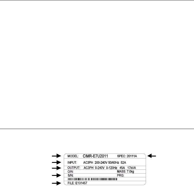
Nameplate Information
A nameplate is attached to the right side of each Drive. The following nameplate is an example for a standard Drive.
Drive Model Number
Input PowerInputSpecificationsPower Rating
Output PowerOutputSpecificationsPower Rating
Serial Number
UL File Number
Note: The Drive Model Number and Drive Spec Number are required to completely identify a Drive.
Fig 1.1 E7 Drive Nameplate
Drive Enclosure and
Drive Spec Number
Revision Code
 Weight
Physical Installation 1 - 3

Drive Model Numbers
The model number on the nameplate indicates the design specification, voltage, and rating of the Drive in alphanumeric codes.
|
|
|
|
|
CIMR – E7 U 2 0 11 |
|
||||||
|
|
AC Drive |
|
|
|
|
|
|
|
|
|
|
|
|
|
|
|
|
|
|
|
|
|
||
|
|
|
|
|||||||||
|
|
E7 Family |
|
|
|
|
|
|
|
|||
|
|
|
|
|
|
|
|
|
||||
|
|
|
|
|
|
|
|
|
|
|
|
|
|
|
No. |
|
|
Spec |
|
|
|
|
Rating |
||
|
|
|
|
|
|
|||||||
|
|
|
|
|
|
|
|
|||||
|
|
U |
|
UL Specification |
|
|
|
|
|
|||
|
|
|
|
|
|
|
|
|
|
|
|
|
No. |
|
|
Voltage |
|
|
|
|
|
||||
|
|
|
|
|
|
|||||||
2 |
|
|
3-phase, 208-240Vac |
|
|
|
|
|
||||
|
|
|
|
|
|
|
|
|
|
|||
4 |
|
|
3-phase, 480Vac |
|
|
|
|
|
||||
Fig 1.2 Drive Model Number Structure
Drive Enclosure and Revision Code
The Drive SPEC number on the nameplate indicates the voltage, Drive rating, enclosure type, and the revision code of the Drive in alphanumeric codes.
2 011 1 A
|
|
No. |
Voltage |
|
|
|
|
|
|
|
|
Hardware Revision |
|
||
|
|
|
|
|
|
|
|
|
|||||||
|
|
|
|
|
|
|
|
|
|
||||||
|
|
2 |
3-phase, 208 - 240Vac |
|
|
|
|
|
|
|
|
|
|
|
|
|
|
4 |
3-phase, 480Vac |
|
|
|
|
|
|
|
|
|
|
|
|
|
|
|
|
|
|
|
|
|
|
|
|
|
|
|
|
|
|
|
|
|
|
|
|
|
|
|
|
|
|
|
|
|
|
|
|
Rating |
|
|
|
|
|
|
No. |
|
|
Enclosure Type |
|
|
|
|
|
|
|
|
|
|
|||||||
|
|
|
|
|
|
|
|
|
0 |
|
|
Open chassis (IEC IP00) |
|||
|
|
|
|
|
|
|
|
|
|
1 |
|
|
NEMA Type 1 (IEC IP20) |
||
|
|
|
|
|
|
|
|
|
|
||||||
|
|
|
|
Fig 1.3 SPEC Number Structure |
|||||||||||
|
|
Open Chassis Type (IEC IP00) |
|
|
|
|
|
|
|
|
|
||||
|
|
|
|
|
|
|
|
|
|
|
|||||
|
|
Protected so that parts of the human body cannot reach electrically charged parts from the front when the |
|||||||||||||
|
|
Drive is mounted in a control panel, also called (protected chassis). |
|||||||||||||
TERMS |
|
NEMA Type 1 (IEC IP20) |
|
|
|
|
|
|
|
|
|
||||
|
|
The Drive is shielded from the exterior, and can thus be mounted to the interior wall of a building |
|||||||||||||
|
|
(not necessarily enclosed in a control panel). The protective structure conforms to the standards of NEMA |
|||||||||||||
|
|
Type 1 in the USA. All protective covers (Fig 1.4) must be installed to conform with IEC IP20 and NEMA Type |
|||||||||||||
|
|
1 requirements. |
|
|
|
|
|
|
|
|
|
||||
|
|
|
|
|
|
|
|
|
|
|
|
|
|
|
|
Physical Installation 1 - 4
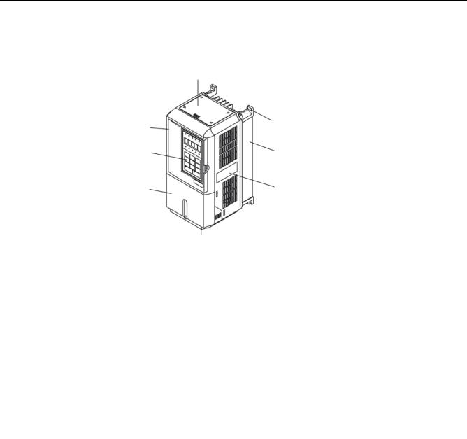
Component Names
Models CIMR-E7U20P4 thru 2018 (25HP @ 208V/240V) and 40P4 thru 4018 (30HP @ 480V)
The external appearance, component names, and terminal arrangement of the Drive are shown in Fig 1.4. and 1.5.
Top protective cover
Front cover |
Mounting hole |
|
|
Digital Operator |
Diecast Heat Sink |
Terminal cover |
Nameplate |
Bottom protective cover
Fig 1.4 Drive Appearance
Fig 1.5 Terminal Arrangement (Terminal Cover Removed)
Physical Installation 1 - 5

Models CIMR-E7U2022 thru 2110 (30HP and above @ 208V/240V) and 4030 thru 4300 (40HP and above @ 480V)
The external appearance, component names, and terminal arrangement of the Drive are shown in Fig 1.6 and 1.7.
|
holes |
|
Mountingting holes |
Drive cover |
|
Drive cover |
|
Front cover |
Cooling fan |
Cooling fan |
|
Front cover |
|
DigitalOperator |
|
Terminal cover |
Nameplate |
Nameplate |
|
Terminal cover |
|
Fig 1.6 Drive Appearance
|
Charge indicator |
Control circuit |
|
terminals |
|
Main circuit |
|
terminals |
|
Ground terminal |
Ground terminal |
Fig 1.7 Terminal Arrangement (Terminal Cover Removed)
Physical Installation 1 - 6
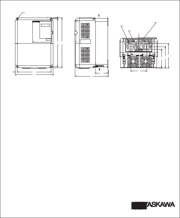
Exterior and Mounting Dimensions
DIMENSIONS: E7 (NEMA 1) 208/240V (3.6-74.8 AMPS) 480V (1.8- 40.0 AMPS)
FRONT VIEW |
|
|
|
SIDE VIEW |
||||||
MOUNTING HOLES |
|
|
|
|
AIR |
|||||
FOR "A" SIZE SCREW |
|
|
|
|
||||||
|
|
H2 |
|
|
||||||
|
|
|
|
|
|
|
|
|
|
|
|
H1 |
H |
|
W2 |
W1 |
AIR |
|
D1 |
|||
|
W |
||
|
D |
||
|
|
1.38 DIA.
(2) HOLES SIZE "J"
.87 DIA. |
C |
L |
E |
C |
B |
F |
BOTTOM VIEW
|
|
RATED |
|
|
|
|
|
|
|
DIMENSIONS IN INCHES |
|
|
|
|
|
|
|
||
|
MODEL |
OUTPUT |
|
|
|
|
|
|
|
|
|
|
|
|
|
APPROX. |
|||
RATED |
NOMINAL |
|
|
|
|
|
|
|
|
|
|
|
|
|
|
||||
INPUT |
CIMR-E7U |
CURRENT |
|
HP |
MOUNTING |
|
|
|
|
|
|
|
|
|
|
|
|
WEIGHT |
|
|
H |
W |
H2 |
W2 |
D |
D1 |
A |
B |
C |
E |
F |
J |
(LBS.) |
||||||
|
|
(AMPS) |
|
|
H1 |
W1 |
|
|
|
|
|
|
|
|
|
|
|
|
|
|
20P41 |
3.6 |
1/2 |
3/4- |
10.47 |
4.96 |
11.02 |
5.51 |
.28 |
.28 |
6.30 |
1.54 |
#10 |
--- |
3.35 |
4.73 |
1.97 |
1.10 |
6.6 |
|
|
|
|
|
|
|
|
|
|
|
|
|
|
|
|
|
|
|
|
|
20P71 |
4.6 |
|
1 |
10.47 |
4.96 |
11.02 |
5.51 |
.28 |
.28 |
6.30 |
1.54 |
#10 |
--- |
3.35 |
4.73 |
1.97 |
1.10 |
6.6 |
|
|
|
|
|
|
|
|
|
|
|
|
|
|
|
|
|
|
|
|
|
21P51 |
7.8 |
|
2 |
10.47 |
4.96 |
11.02 |
5.51 |
.28 |
.28 |
6.30 |
1.54 |
#10 |
--- |
3.35 |
4.73 |
1.97 |
1.10 |
6.6 |
|
|
|
|
|
|
|
|
|
|
|
|
|
|
|
|
|
|
|
|
|
22P21 |
10.8 |
|
3 |
10.47 |
4.96 |
11.02 |
5.51 |
.28 |
.28 |
6.30 |
1.54 |
#10 |
--- |
3.35 |
4.73 |
1.97 |
1.10 |
6.6 |
208V |
|
|
|
|
|
|
|
|
|
|
|
|
|
|
|
|
|
|
|
23P71 |
16.8 |
|
5 |
10.47 |
4.96 |
11.02 |
5.51 |
.28 |
.28 |
7.09 |
2.32 |
#10 |
--- |
4.14 |
5.52 |
1.97 |
1.10 |
8.8 |
|
|
|
||||||||||||||||||
|
|
|
|
|
|
|
|
|
|
|
|
|
|
|
|
|
|
|
|
|
27P51 |
31.0 |
7.5-10 |
11.22 |
7.32 |
11.81 |
7.87 |
.28 |
.28 |
7.87 |
2.58 |
1/4 |
4.63 |
5.11 |
6.21 |
3.07 |
1.38 |
13.2 |
|
|
|
|
|
|
|
|
|
|
|
|
|
|
|
|
|
|
|
|
|
|
20111 |
46.2 |
|
15 |
11.22 |
7.32 |
12.20 |
7.87 |
.28 |
.28 |
7.87 |
2.58 |
1/4 |
4.63 |
5.11 |
6.21 |
3.07 |
1.38 |
15.4 |
|
|
|
|
|
|
|
|
|
|
|
|
|
|
|
|
|
|
|
|
|
20151 |
59.4 |
|
20 |
13.19 |
8.50 |
13.78 |
9.45 |
.30 |
.47 |
8.27 |
3.07 |
1/4 |
5.12 |
5.79 |
6.65 |
3.94 |
1.73 |
24.2 |
|
|
|
|
|
|
|
|
|
|
|
|
|
|
|
|
|
|
|
|
|
20181 |
74.8 |
|
25 |
13.19 |
8.50 |
14.96 |
9.45 |
.30 |
.47 |
8.27 |
3.07 |
1/4 |
5.12 |
5.79 |
6.65 |
3.94 |
1.73 |
24.2 |
|
|
|
|
|
|
|
|
|
|
|
|
|
|
|
|
|
|
|
|
|
|
|
|
|
|
|
|
|
|
|
|
|
|
|
|
|
|
|
|
|
20P41 |
3.6 |
1/2 |
3/4- |
10.47 |
4.96 |
11.02 |
5.51 |
.28 |
.28 |
6.30 |
1.54 |
#10 |
--- |
3.35 |
4.73 |
1.97 |
1.10 |
6.6 |
|
|
|
|
|
|
|
|
|
|
|
|
|
|
|
|
|
|
|
|
|
20P71 |
4.6 |
|
1 |
10.47 |
4.96 |
11.02 |
5.51 |
.28 |
.28 |
6.30 |
1.54 |
#10 |
--- |
3.35 |
4.73 |
1.97 |
1.10 |
6.6 |
|
|
|
|
|
|
|
|
|
|
|
|
|
|
|
|
|
|
|
|
|
21P51 |
7.8 |
|
2 |
10.47 |
4.96 |
11.02 |
5.51 |
.28 |
.28 |
6.30 |
1.54 |
#10 |
--- |
3.35 |
4.73 |
1.97 |
1.10 |
6.6 |
|
|
|
|
|
|
|
|
|
|
|
|
|
|
|
|
|
|
|
|
|
22P21 |
10.8 |
|
3 |
10.47 |
4.96 |
11.02 |
5.51 |
.28 |
.28 |
6.30 |
1.54 |
#10 |
--- |
3.35 |
4.73 |
1.97 |
1.10 |
6.6 |
|
|
|
|
|
|
|
|
|
|
|
|
|
|
|
|
|
|
|
|
240V |
23P71 |
16.8 |
|
5 |
10.47 |
4.96 |
11.02 |
5.51 |
.28 |
.28 |
7.09 |
2.32 |
#10 |
--- |
4.14 |
5.52 |
1.97 |
1.10 |
8.8 |
|
|
|
|
|
|
|
|
|
|
|
|
|
|
|
|
|
|
|
|
|
25P51 |
23.0 |
|
7.5 |
10.47 |
4.96 |
11.02 |
5.51 |
.28 |
.28 |
7.09 |
2.32 |
#10 |
--- |
4.14 |
5.52 |
1.97 |
1.10 |
8.8 |
|
|
|
|
|
|
|
|
|
|
|
|
|
|
|
|
|
|
|
|
|
27P51 |
31.0 |
|
10 |
11.22 |
7.32 |
11.81 |
7.87 |
.28 |
.28 |
7.87 |
2.58 |
1/4 |
4.63 |
5.11 |
6.21 |
3.07 |
1.38 |
13.2 |
|
|
|
|
|
|
|
|
|
|
|
|
|
|
|
|
|
|
|
|
|
20111 |
46.2 |
|
15 |
11.22 |
7.32 |
12.20 |
7.87 |
.28 |
.28 |
7.87 |
2.58 |
1/4 |
4.63 |
5.11 |
6.21 |
3.07 |
1.38 |
15.4 |
|
|
|
|
|
|
|
|
|
|
|
|
|
|
|
|
|
|
|
|
|
20151 |
59.4 |
|
20 |
13.19 |
8.50 |
13.78 |
9.45 |
.30 |
.47 |
8.27 |
3.07 |
1/4 |
5.12 |
5.79 |
6.65 |
3.94 |
1.73 |
24.2 |
|
|
|
|
|
|
|
|
|
|
|
|
|
|
|
|
|
|
|
|
|
20181 |
74.8 |
|
25 |
13.19 |
8.50 |
14.96 |
9.45 |
.30 |
.47 |
8.27 |
3.07 |
1/4 |
5.12 |
5.79 |
6.65 |
3.94 |
1.73 |
24.2 |
|
|
|
|
|
|
|
|
|
|
|
|
|
|
|
|
|
|
|
|
|
|
|
|
|
|
|
|
|
|
|
|
|
|
|
|
|
|
|
|
|
40P41 |
1.8 |
1/2 |
3/4- |
10.47 |
4.96 |
11.02 |
5.51 |
.28 |
.28 |
6.30 |
1.54 |
#10 |
--- |
3.35 |
4.73 |
1.97 |
1.10 |
6.6 |
|
|
|
|
|
|
|
|
|
|
|
|
|
|
|
|
|
|
|
|
|
40P71 |
2.1 |
|
1 |
10.47 |
4.96 |
11.02 |
5.51 |
.28 |
.28 |
6.30 |
1.54 |
#10 |
--- |
3.35 |
4.73 |
1.97 |
1.10 |
6.6 |
|
|
|
|
|
|
|
|
|
|
|
|
|
|
|
|
|
|
|
|
|
41P51 |
3.7 |
|
2 |
10.47 |
4.96 |
11.02 |
5.51 |
.28 |
.28 |
6.30 |
1.54 |
#10 |
--- |
3.35 |
4.73 |
1.97 |
1.10 |
6.6 |
|
|
|
|
|
|
|
|
|
|
|
|
|
|
|
|
|
|
|
|
|
42P21 |
5.3 |
|
3 |
10.47 |
4.96 |
11.02 |
5.51 |
.28 |
.28 |
7.09 |
2.32 |
#10 |
--- |
4.14 |
5.52 |
1.97 |
1.10 |
8.8 |
|
|
|
|
|
|
|
|
|
|
|
|
|
|
|
|
|
|
|
|
480V |
43P71 |
7.6 |
|
5 |
10.47 |
4.96 |
11.02 |
5.51 |
.28 |
.28 |
7.09 |
2.32 |
#10 |
--- |
4.14 |
5.52 |
1.97 |
1.10 |
8.8 |
|
|
|
|
|
|
|
|
|
|
|
|
|
|
|
|
|
|
|
|
45P51 |
12.5 |
|
7.5 |
10.47 |
4.96 |
11.02 |
5.51 |
.28 |
.28 |
7.09 |
2.32 |
#10 |
--- |
4.14 |
5.52 |
1.97 |
1.10 |
8.8 |
|
|
|
||||||||||||||||||
|
|
|
|
|
|
|
|
|
|
|
|
|
|
|
|
|
|
|
|
|
47P51 |
17.0 |
|
10 |
11.22 |
7.32 |
11.81 |
7.87 |
.28 |
.28 |
7.87 |
2.58 |
1/4 |
4.63 |
5.11 |
6.21 |
3.07 |
1.38 |
13.2 |
|
|
|
|
|
|
|
|
|
|
|
|
|
|
|
|
|
|
|
|
|
49P01 |
21.0 |
|
15 |
11.22 |
7.32 |
11.81 |
7.87 |
.28 |
.28 |
7.87 |
2.58 |
1/4 |
4.63 |
5.11 |
6.21 |
3.07 |
1.38 |
13.2 |
|
|
|
|
|
|
|
|
|
|
|
|
|
|
|
|
|
|
|
|
|
40111 |
27.0 |
|
20 |
11.22 |
7.32 |
11.81 |
7.87 |
.28 |
.28 |
7.87 |
2.58 |
1/4 |
4.63 |
5.11 |
6.21 |
3.07 |
1.38 |
13.2 |
|
|
|
|
|
|
|
|
|
|
|
|
|
|
|
|
|
|
|
|
|
40151 |
34.0 |
|
25 |
13.19 |
8.50 |
13.78 |
9.45 |
.30 |
.47 |
8.27 |
3.07 |
1/4 |
5.12 |
5.79 |
6.65 |
3.94 |
1.73 |
22 |
|
|
|
|
|
|
|
|
|
|
|
|
|
|
|
|
|
|
|
|
|
40181 |
40.0 |
|
30 |
13.19 |
8.50 |
13.78 |
9.45 |
.30 |
.47 |
8.27 |
3.07 |
1/4 |
5.12 |
5.79 |
6.65 |
3.94 |
1.73 |
22 |
|
|
|
|
|
|
|
|
|
|
|
|
|
|
|
|
|
|
|
|
FOR REFERENCE ONLY UNLESS PROPERLY ENDORSED.
IN ORDER TO ACHIEVE ADEQUATE COOLING
THE DRIVE MUST BE POSITIONED TO ALLOW A MINIMUM OF FREE AIR SPACE OF 1.2 INCHES ON SIDES AND
5 INCHES TOP AND BOTTOM
DR BY |
RIP 9.29.04 |
APPVL. |
TA 9.29.04 |
Physical Installation 1 - 7

DIMENSIONS: E7 (NEMA 1) |
208/240V (88.0-115 AMPS) 480V (52.0-125 AMPS) |
|
|
|
APPROX. |
CURRENT |
|
WEIGHT |
|
(LBS.) |
|
|
|
|
|
Physical Installation |
1 - 8 |
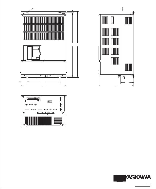
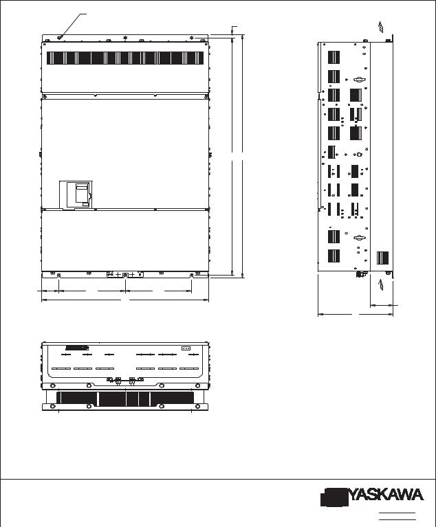
DIMENSIONS: E7 (PROTECTED CHASSIS) |
208-230V (162-415 AMPS) |
|
|
|
|||
480V (156-304 AMPS) |
|
|
|
||||
|
|
|
|
||||
FRONT VIEW |
|
|
|
|
|
|
|
MOUNTING HOLES |
|
|
|
H2 |
|
|
AIR |
|
|
|
|
|
|||
FOR "A" SIZE SCREW |
|
|
|
|
|
||
|
H1 |
H |
|
|
AIR |
W2 |
W1 |
D1 |
|
W |
D |
|
|
|
RATED |
|
|
|
DIMENSIONS IN INCHES |
|
|
|
|
APPROX. |
|||
|
|
MODEL |
OUTPUT |
|
|
|
|
|
|
|
|||||
|
RATED |
NOM. |
|
|
|
|
|
|
|
|
|
|
WEIGHT |
||
|
INPUT |
CIMR-E7U |
CURRENT |
HP |
MOUNTING |
H |
W |
H2 |
|
W2 |
D |
D1 |
A |
(LBS.) |
|
|
|
|
(AMPS) |
|
H1 |
W1 |
|
|
|
|
|
|
|
|
|
|
|
20370 |
162 |
50 |
22.64 |
9.84 |
23.62 |
14.76 |
.49 |
|
2.46 |
11.81 |
3.94 |
3/8 |
125 |
|
|
20450 |
192 |
60 |
22.64 |
9.84 |
23.62 |
14.76 |
.49 |
|
2.46 |
12.99 |
5.12 |
3/8 |
139 |
|
208V |
20550 |
215 |
75 |
27.56 |
12.80 |
28.54 |
17.72 |
.49 |
|
2.46 |
13.78 |
5.12 |
3/8 |
189 |
|
20750 |
312 |
100 |
27.56 |
12.80 |
28.54 |
17.72 |
.49 |
|
2.46 |
13.78 |
5.12 |
3/8 |
191 |
|
|
|
|
|||||||||||||
|
|
20900 |
360 |
125 |
32.28 |
14.57 |
33.46 |
19.69 |
.59 |
|
2.56 |
14.17 |
5.12 |
3/8 |
238 |
|
|
21100 |
415 |
150 |
33.66 |
17.52 |
34.84 |
22.64 |
.59 |
|
2.56 |
14.96 |
5.51 |
3/8 |
330 |
|
|
20370 |
162 |
50-60 |
22.64 |
9.84 |
23.62 |
14.76 |
.49 |
|
2.46 |
11.81 |
3.94 |
3/8 |
125 |
|
230V |
20450 |
192 |
75 |
22.64 |
9.84 |
23.62 |
14.76 |
.49 |
|
2.46 |
12.99 |
5.12 |
3/8 |
139 |
|
|
|
|
|
|
|
|
|
|
|
|
|
|
|
|
|
|
20750 |
312 |
100-125 |
27.56 |
12.80 |
28.54 |
17.72 |
.49 |
|
2.46 |
13.78 |
5.12 |
3/8 |
191 |
|
|
|
|
|
|
|
|
|
|
|
|
|
|
|
|
|
|
20900 |
360 |
150 |
32.28 |
14.57 |
33.46 |
19.69 |
.59 |
|
2.56 |
14.17 |
5.12 |
3/8 |
238 |
|
|
|
|
|
|
|
|
|
|
|
|
|
|
|
|
|
|
40750 |
156 |
125 |
27.56 |
12.80 |
28.54 |
17.72 |
.49 |
|
2.46 |
13.78 |
5.12 |
3/8 |
194 |
|
480V |
40900 |
180 |
150 |
27.56 |
12.80 |
28.54 |
17.72 |
.49 |
|
2.46 |
13.78 |
5.12 |
3/8 |
196 |
|
|
41100 |
240 |
200 |
32.28 |
14.57 |
33.46 |
19.69 |
.59 |
|
2.56 |
14.17 |
5.12 |
3/8 |
224 |
|
|
41600 |
304 |
250 |
33.66 |
17.52 |
36.06 |
22.64 |
.59 |
|
2.56 |
14.96 |
5.51 |
3/8 |
352 |
|
|
|
|
|
|
|
|
|
|
|
|
|
|
|
|
FOR REFERENCE ONLY UNLESS PROPERLY ENDORSED.
IN ORDER TO ACHIEVE ADEQUATE COOLING
THE DRIVE MUST BE POSITIONED TO ALLOW A MINIMUM OF FREE AIR SPACE OF 1.2 INCHES ON SIDES AND
5 INCHES TOP AND BOTTOM
DR BY RIP 9.29.04 APPVL. TA 9.29.04
Physical Installation 1 - 9
DIMENSIONS: E7 (PROTECTED CHASSIS)
MOUNTING HOLES |
|
FOR "A" SIZE SCREWS |
AIR |
|
H2 |
H1 H
W2 |
W1 |
|
W1 |
|
|
W |
AIR |
|
|
D1 |
|
|
|
|
|
|
|
|
D |
|
|
RATED |
|
|
|
|
|
DIMENSIONS IN INCHES |
|
APPROX. |
|||
RATED |
MODEL |
OUTPUT |
NOM. |
|
|
|
|
|
|||||
|
|
|
|
|
|
|
|
|
WEIGHT |
||||
INPUT |
CIMR-E7U |
CURRENT |
HP |
MOUNTING |
H |
W |
H2 |
W2 |
D |
D1 |
A |
(LBS.) |
|
|
|
(AMPS) |
|
H1 |
W1 |
|
|
|
|
|
|
|
|
|
41850 |
414 |
300-350 |
50.00 |
10.63 |
51.38 |
27.95 |
.79 |
3.35 |
16.34 |
4.94 |
3/8 |
572 |
|
|
|
|
|
|
|
|
|
|
|
|
|
|
480V |
42200 |
515 |
400-450 |
50.00 |
10.63 |
51.38 |
27.95 |
.79 |
3.35 |
16.34 |
4.94 |
3/8 |
616 |
|
|
|
|
|
|
|
|
|
|
|
|
|
|
|
43000 |
675 |
500 |
56.70 |
14.37 |
58.07 |
36.06 |
.79 |
3.66 |
16.34 |
4.94 |
3/8 |
891 |
|
|
|
|
|
|
|
|
|
|
|
|
|
|
FOR REFERENCE ONLY UNLESS PROPERLY ENDORSED.
IN ORDER TO ACHIEVE ADEQUATE COOLING
THE DRIVE MUST BE POSITIONED TO ALLOW A MINIMUM OF FREE AIR OF 1.2 INCHES ON SIDES AND
5 INCHES TOP AND BOTTOM
DR BY RIP 8-02 APPVL. TBS 9.5.02
Physical Installation 1 - 10
Heat Loss Data
Table 1.3 200V Class Heat Loss Data
|
Drive |
Rated |
Cooling |
Internal |
Total |
|
|
TYPE |
(Inverter) |
Output |
Watt |
Cooling |
|||
Fin Side |
Unit Side |
||||||
CIMR-E7U |
Capacity |
Current |
Loss |
Method |
|||
(W) |
(W) |
||||||
|
(kVA) |
(A) |
(W) |
|
|||
|
|
|
|
||||
20P4 |
1.4 |
3.6 |
19 |
39 |
58 |
Self |
|
20P7 |
1.8 |
4.6 |
26 |
42 |
68 |
Self |
|
21P5 |
3.0 |
7.8 |
48 |
50 |
98 |
Self |
|
22P2 |
4.1 |
10.8 |
68 |
59 |
127 |
Self |
|
23P7 |
6.4 |
16.8 |
110 |
74 |
184 |
Fan |
|
25P5 |
8.8 |
23 |
164 |
84 |
248 |
Fan |
|
27P5 |
12 |
31 |
219 |
113 |
332 |
Fan |
|
2011 |
18 |
46.2 |
357 |
168 |
524 |
Fan |
|
2015 |
23 |
59.4 |
416 |
182 |
597 |
Fan |
|
2018 |
29 |
74.8 |
472 |
208 |
680 |
Fan |
|
2022 |
34 |
88 |
583 |
252 |
835 |
Fan |
|
2030 |
44 |
115 |
883 |
333 |
1217 |
Fan |
|
2037 |
62 |
162 |
1010 |
421 |
1430 |
Fan |
|
2045 |
73 |
192 |
1228 |
499 |
1727 |
Fan |
|
2055 |
82 |
215 |
1588 |
619 |
2206 |
Fan |
|
2075 |
120 |
312 |
1956 |
844 |
2800 |
Fan |
|
2090 |
140 |
360 |
2194 |
964 |
3157 |
Fan |
|
2110 |
160 |
415 |
2733 |
1234 |
3967 |
Fan |
Physical Installation 1 - 11

Table 1.4 400V Class Heat Loss Data
|
Drive |
Rated |
Cooling |
Internal |
Total |
|
|
TYPE |
(Inverter) |
Output |
Watt |
Cooling |
|||
Fin Side |
Unit Side |
||||||
CIMR-E7U |
Capacity |
Current |
Loss |
Method |
|||
(W) |
(W) |
||||||
|
(kVA) |
(A) |
(W) |
|
|||
|
|
|
|
||||
40P4 |
1.4 |
1.8 |
14 |
39 |
53 |
Self |
|
40P7 |
1.6 |
2.1 |
17 |
41 |
58 |
Self |
|
41P5 |
2.8 |
3.7 |
36 |
48 |
84 |
Self |
|
42P2 |
4.0 |
5.3 |
59 |
56 |
115 |
Fan |
|
43P7 |
5.8 |
7.6 |
80 |
68 |
140 |
Fan |
|
44P0 |
6.6 |
8.7 |
90 |
70 |
160 |
Fan |
|
45P5 |
9.5 |
12.5 |
127 |
81 |
209 |
Fan |
|
47P5 |
13 |
17 |
193 |
114 |
307 |
Fan |
|
49P0 |
16 |
21 |
232 |
158 |
390 |
Fan |
|
4011 |
21 |
27 |
232 |
158 |
390 |
Fan |
|
4015 |
26 |
34 |
296 |
169 |
465 |
Fan |
|
4018 |
30 |
40 |
389 |
201 |
590 |
Fan |
|
4022 |
38 |
50.4 |
420 |
233 |
653 |
Fan |
|
4024 |
40 |
52 |
691 |
297 |
989 |
Fan |
|
4030 |
51 |
67.2 |
691 |
297 |
989 |
Fan |
|
4037 |
59 |
77 |
801 |
332 |
1133 |
Fan |
|
4045 |
73 |
96 |
901 |
386 |
1287 |
Fan |
|
4055 |
95 |
125 |
1204 |
478 |
1682 |
Fan |
|
4075 |
120 |
156 |
1285 |
562 |
1847 |
Fan |
|
4090 |
140 |
180 |
1614 |
673 |
2287 |
Fan |
|
4110 |
180 |
240 |
1889 |
847 |
2736 |
Fan |
|
4132 |
200 |
260 |
2388 |
1005 |
3393 |
Fan |
|
4160 |
230 |
304 |
2636 |
1144 |
3936 |
Fan |
|
4185 |
315 |
414 |
2791 |
1328 |
3964 |
Fan |
|
4220 |
390 |
515 |
3797 |
1712 |
5509 |
Fan |
|
4300 |
510 |
675 |
5838 |
2482 |
8319 |
Fan |
Physical Installation 1 - 12

Checking and Controlling the Installation Site
Install the Drive as described below and maintain optimum conditions.
WARNING |
The Drive heatsink temperature may exceed 158°F (70°C). Therefore, mount the Drive to a surface suitable |
|
for high temperature. |
||
|
||
|
|
Installation Site
Locate the E7 Drive as close as possible to the motor. Install the Drive under the following conditions in UL Pollution Degree 1 & 2 environments. This excludes wet locations where surfaces may become conductive due to moisture and contaminant loading.
|
Table 1.5 Installation Site Specifications |
|
|
|
|
|
|
Type |
Ambient Operating Temperature |
Humidity |
Plenum Rated |
NEMA Type 1 |
14°F to 104°F(-10 to +40°C) |
95% RH or less (no condensation) |
Yes |
|
|
|
|
Open Chassis |
14°F to 113°F(-10 to +45°C) |
95% RH or less (no condensation) |
No |
|
|
|
|
Protective covers are attached to the top and bottom of the Drive. It is recommended to remove the protective covers before operating a CIMR-E7U2030/4055 Drive and smaller in a panel to obtain the 113°F (45°C) ambient operating temperature.
Observe the following precautions when installing the Drive:
•in a clean location which is free from oil mist and dust.
•in an environment where metal shavings, oil, water, or other foreign materials will not get into the Drive enclosure.
•in a location free from radioactive materials.
•in a location free from harmful gasses and liquids.
•in a location free from excessive vibration.
•in a location free from chlorides.
•in a location away from direct sunlight.
•on a non-combustible surface.
Controlling the Ambient Temperature
To enhance the reliability of operation, the Drive should be installed in an environment free from extreme temperature variations. If the Drive is installed in an enclosure, use a cooling fan or air conditioner to maintain the internal air temperature below 113°F (45°C).
Protecting the Drive from Foreign Matter
During Drive installation and project construction it is possible to have foreign matter, such as metal shavings or wire clippings, fall inside the Drive. To prevent foreign matter from falling into the Drive, place a temporary cover over the Drive.
Always remove the temporary cover from the Drive before Start-Up. Otherwise, ventilation will be reduced, causing the Drive to overheat.
Physical Installation 1 - 13
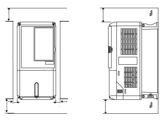
Installation Orientation and Clearances
Install the Drive vertically so as not to reduce the cooling efficiency. When installing the Drive, always provide the following installation clearances to allow normal heat dissipation. For 3HP, 208V/240V (CIMR-E7U22P2 and below) or 2HP, 480V (CIMR-E7U41P5 and below), ensure that the heatsink is against a closed surface to avoid diverting cooling air around the heatsink.
4.75 in (120 mm. minimum) |
4.75 in (120 mm. minimum) |
Air
1.2 in
(30.5 MM.) min.
1.2 in |
(30.5 mm. minimum) |
4.75 in (50 mm. minimum) |
1.2 in |
(30.5 mm. minimum) |
4.75 in (120 mm. minimum)
Air
Horizontal Clearance |
Vertical Clearance |
Fig 1.8 Drive Installation Orientation and Clearance
|
1. The same clearance is required horizontally and vertically for both Open Chassis (IP00) and NEMA |
|
|
Type 1 Drives. |
|
IMPORTANT |
2. Always remove the top and bottom protection covers before installing a CIMR-E7U2018/4018 and |
|
smaller Drive in a panel. |
||
|
||
|
Always provide enough clearance for lifting eye bolts and the main circuit wiring when installing a |
|
|
CIMR-E7U2022/4030 and larger Drive in a panel. |
|
|
|
Physical Installation 1 - 14

Removing and Attaching the Terminal Cover
Remove the terminal cover to connect cables to the control circuit and main circuit terminals.
Prior to removing any protective cover or wiring any part of the Drive, remove all power sources, including
main input power and control circuit power. Wait a minimum of 5 minutes after power removal, before WARNING removing any cover. The charge lamp located within the Drive should be off prior to working inside. Even if
the charge lamp is off, one must measure the AC input, output, and DC Bus potential to insure safe levels prior to resuming work. Failure to adhere to this warning may result in personal injury or death.
Removing the Terminal Cover
Models CIMR-E7U20P4 thru 2018 (0.5HP to 25HP @ 208V/240V) and 40P4 thru 4018 (0.5HP to 30HP @ 480V)
Loosen the screw at the bottom of the terminal cover, press in on the sides of the terminal cover in the directions of arrows 1, and then lift up on the terminal in the direction of arrow 2. Refer to Fig 1.9
Models CIMR-E7U2022 thru 2110 (30HP to 150HP @ 208V/240V) and 4030 thru 4300 (40HP to 500HP @ 480V)
Loosen the screws on the left and right at the top of the terminal cover, pull down the terminal cover in the direction of arrow 1 and then lift up on the terminal cover in the direction of arrow 2. Refer to Fig 1.10
 1
1
2
Fig 1.9 Removing the Terminal Cover
Fig 1.10 Removing the Terminal Cover
Attaching the Terminal Cover
After wiring the terminal block, attach the terminal cover by reversing the removal procedure.
For Models CIMR-E7U2018/4018 and smaller, insert the tab on the top of the terminal cover into the groove on the Drive and press in on the bottom of the terminal cover until it snaps into place.
For Drives CIMR-E7U2022/4030 and larger, insert the tab on the top of the terminal cover into the groove on the Drive, and secure the terminal cover by lifting it up toward the top of the Drive.
Physical Installation 1 - 15
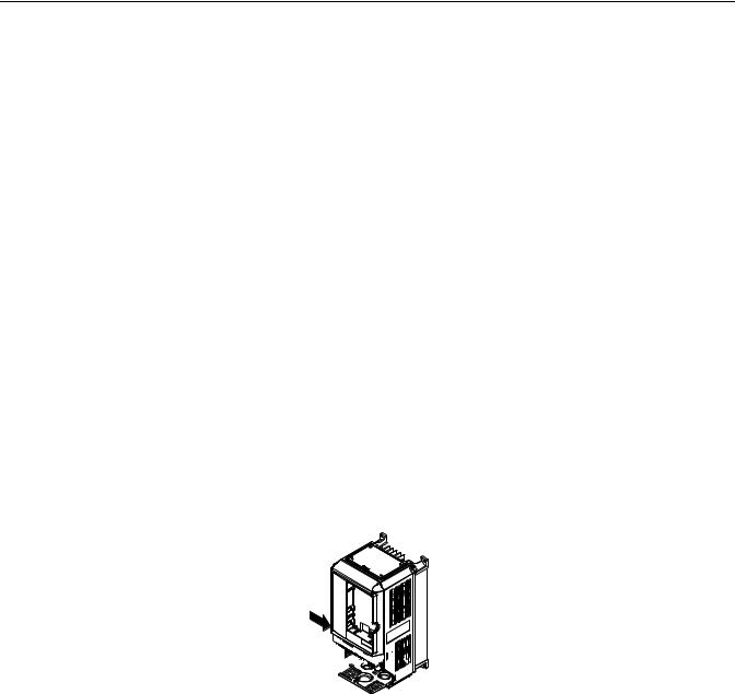
Removing/Attaching the Digital Operator and Front Cover
Models CIMR-E7U20P4 thru 2018 (0.5HP to 25HP @ 208V/240V) and 40P4 thru 4018 (0.5HP to 30HP @ 480V)
For Models CIMR-E7U2018/4018 and smaller, remove the terminal cover and then use the following procedures to remove the Digital Operator and front cover.
Removing the Digital Operator
Press on the side of the Digital Operator in the direction of arrow 1 to unlock, then lift the Digital Operator in the direction of arrow 2 to remove it as shown in Fig 1.11.
2 1
Fig 1.11 Removing the Digital Operator
Removing the Front Cover
Press the left and right sides of the front cover in the direction of arrows 1 and lift the bottom of cover in the direction of arrow 2 to remove it as shown in Fig 1.12.
1
2 


Fig 1.12 Removing the Front Cover
Attaching the Front Cover
Mount the front cover to the Drive by performing the steps to remove the front cover in reverse order.
1.Do not mount the front cover with the Digital Operator attached to the front cover; this may cause the Digital Operator to malfunction due to imperfect contact.
2.Insert the tab of the upper part of the front cover into the groove of the Drive and press the lower part of the front cover onto the Drive until the front cover snaps into place.
Physical Installation 1 - 16
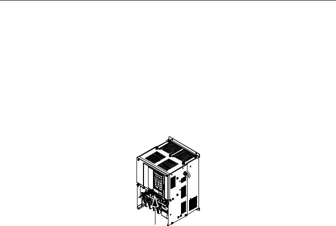
Models CIMR-E7U2022 thru 2110 (30HP to 150HP @ 208V/240V) and 4030 thru 4300 (40HP to 500HP @ 480V)
For Models CIMR-E7U2022/4030 and larger, remove the terminal cover and then use the following procedures to remove the Digital Operator and front cover.
Removing the Digital Operator
Use the same procedure for Models CIMR-E7U2018/4018 and smaller.
Removing the Front Cover
Loosen all screws on the front cover. Lift up at the location labeled 1 at the top of the control circuit terminal card and move in the direction of arrow 2.
2 |
1 |
Fig 1.13 Removing the Front Cover
Attaching the Front Cover
Attach the front cover by reversing the procedure to remove it.
1.Confirm that the Digital Operator is not mounted on the front cover. Contact faults can occur if the cover is attached while the Digital Operator is mounted to it.
2.Insert the tab on the top of the front cover into the slot on the Drive and press in on the cover until it snaps into place on the Drive.
Physical Installation 1 - 17

Attaching the Digital Operator
After attaching the front cover, mount the Digital Operator onto the Drive using the following procedure.
1.Hook the Digital Operator at A (two locations) on the front cover by moving in the direction of arrow 1 as shown in the following illustration.
2.Press the Digital Operator in the direction of arrow 2 until it snaps in place at B (two locations).
A
1
B
2 
Fig 1.14 Mounting the Digital Operator
1.Do not remove or attach the Digital Operator or mount or remove the front cover using methods other than those described above, damage to the Digital Operator or Drive may occur.
IMPORTANT 2. Never attach the front cover to the Drive with the Digital Operator attached to the front cover. Damage to the Digital Operator may occur. Always attach the front cover to the Drive first, and then attach the Digital Operator to the front cover.
Physical Installation 1 - 18

Chapter 2
Electrical Installation
This chapter describes wiring terminals, main circuit terminal connections, main circuit terminal wiring specifications, control circuit terminals, and control circuit wiring specifications.
Terminal Block Configuration ..................................................... |
2-2 |
Wiring Main Circuit Terminals ................................................... |
2-3 |
Control Wiring........................................................................... |
2-12 |
Electrical Installation 2 - 1
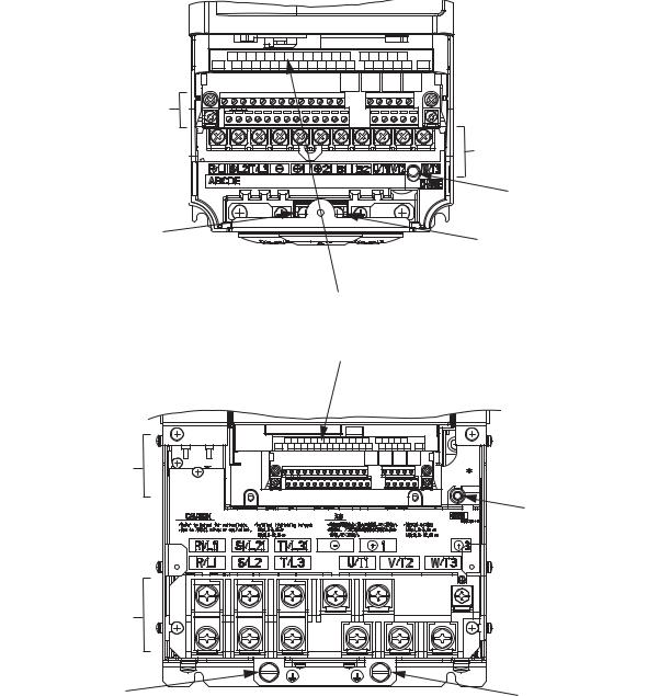
Terminal Block Configuration
The wiring terminals are shown in Fig 2.1.
|
SN SC SP A1 A2 +V AC -V MP AC RP R+ R- |
M5 M6 MA MB MC |
|
|
E(G) |
S1 S2 S3 S4 S5 S6 S7 FM AC AM IG S+ S- |
M3 M4 M1 |
M2 |
E(G) |
Control circuit terminals
Main circuit terminals |
Charge indicator |
Ground terminal |
Ground terminal |
|
Models CIMR-_ _ _ 2018 (25 HP, 208V)/ 4018 (30 HP, 480V) and smaller
Control circuit terminals
Main circuit terminals
Ground terminal
|
SN SC SP A1 A2 +V AC -V MP AC RP R+ R- |
|
M5 M6 MA MB MC |
|
E(G) |
S1 S2 S3 S4 S5 S6 S7 FM AC AM IG S+ |
S- |
M3 M4 M1 M2 |
E(G) |
|
|
|
|
Charge indicator |
Ground terminal
Models CIMR-_ _ _ 2022 (30 HP, 208V)/ 4030 (40 HP, 480V) and larger
Fig 2.1 Drive Terminal Configuration
Electrical Installation 2 - 2
Loading...