


 Loading...
YASKAWA AC Drive 1000-Series Option
LCD Operator
Installation Manual
Type JVOP-180
To properly use the product, read this manual thoroughly and retain for easy reference, inspection, and maintenance. Ensure the end user receives this manual.
1000
LCD
JVOP-180
MANUAL NO. TOBP C730600 29G

Copyright © 2007 YASKAWA ELECTRIC CORPORATION
All rights reserved. No part of this publication may be reproduced, stored in a retrieval system, or transmitted, in any form or by any means, mechanical, electronic, photocopying, recording, or otherwise, without the prior written permission of Yaskawa. No patent liability is assumed with respect to the use of the information contained herein. Moreover, because Yaskawa is constantly striving to improve its high-quality products, the information contained in this manual is subject to change without notice. Every precaution has been taken in the preparation of this manual. Yaskawa assumes no responsibility for errors or omissions. Neither is any liability assumed for damages resulting from the use of the information contained in this publication.
2 |
YASKAWA ELECTRIC TOBP C730600 29G 1000-Series Option JVOP-180 Installation Manual |

Table of Contents
1 PREFACE AND SAFETY . . . . . . . . . . . . . . . . . . . . . . . . . . . . 4 2 PRODUCT OVERVIEW . . . . . . . . . . . . . . . . . . . . . . . . . . . . . .8 3 RECEIVING . . . . . . . . . . . . . . . . . . . . . . . . . . . . . . . . . . . . . .10 4 OPTION COMPONENTS. . . . . . . . . . . . . . . . . . . . . . . . . . . .12 5 INSTALLATION PROCEDURE. . . . . . . . . . . . . . . . . . . . . . .22 6 BASIC OPERATION . . . . . . . . . . . . . . . . . . . . . . . . . . . . . . .28 7 RELATED PARAMETERS . . . . . . . . . . . . . . . . . . . . . . . . . .51 8 OPTION FAULT DIAGNOSTICS. . . . . . . . . . . . . . . . . . . . . .54 9 SPECIFICATIONS . . . . . . . . . . . . . . . . . . . . . . . . . . . . . . . . .56 10 REVISION HISTORY . . . . . . . . . . . . . . . . . . . . . . . . . . . . . .57
YASKAWA ELECTRIC TOBP C730600 29G 1000-Series Option JVOP-180 Installation Manual |
3 |

1 Preface and Safety
1 Preface and Safety
Yaskawa manufactures products used as components in a wide variety of industrial systems and equipment. The selection and application of Yaskawa products remain the responsibility of the equipment manufacturer or end user. Yaskawa accepts no responsibility for the way its products are incorporated into the final system design. Under no circumstances should any Yaskawa product be incorporated into any product or design as the exclusive or sole safety control. Without exception, all controls should be designed to detect faults dynamically and fail safely under all circumstances. All systems or equipment designed to incorporate a product manufactured by Yaskawa must be supplied to the end user with appropriate warnings and instructions as to the safe use and operation of that part. Any warnings provided by Yaskawa must be promptly provided to the end user. Yaskawa offers an express warranty only as to the quality of its products in conforming to standards and specifications published in the Yaskawa manual. NO OTHER WARRANTY, EXPRESS OR IMPLIED, IS OFFERED. Yaskawa assumes no liability for any personal injury, property damage, losses, or claims arising from misapplication of its products.
4 |
YASKAWA ELECTRIC TOBP C730600 29G 1000-Series Option JVOP-180 Installation Manual |
1 Preface and Safety
Applicable Documentation
The following manuals are available for the JVOP-180 LCD Operator Option:
LCD Operator
Yaskawa AC Drive 1000-Series Option LCD Operator Installation Manual
Manual No: TOBP C730600 29 (this book)
Read this manual first.
The installation manual is packaged with the option and contains information required to install the option and set up related unit parameters.
Yaskawa Unit
Yaskawa AC Drive
1000-Series Quick Start Guide
Yaskawa AC Drive
1000-Series Technical Manual
YASKAWA D1000 Series
Power Regenerative Converter
Instruction Manual
YASKAWA R1000 Series
Power Regenerative Unit
Instruction Manual
The unit manuals cover basic installation, wiring, operation procedures, functions, troubleshooting, and maintenance information.
The manuals also include important information about parameter settings and unit tuning. Access these sites to obtain Yaskawa instruction manuals: U.S.: http://www.yaskawa.com
Europe: http://www.yaskawa.eu.com Japan: http://www.e-mechatronics.com
For questions, contact your local Yaskawa sales office or the nearest Yaskawa representative.
Note: Check the option to make sure it is compatible with the A1000. The nameplate on the option must list software number PRG: 0101 or later for compatibility with A1000.
Terms
Note: |
Indicates a supplement or precaution that does not cause unit damage. |
|
≥ PRG: 1012: |
Indicates a unit feature or function that is only available in unit software version 1012 or |
|
greater. |
||
|
||
LED: |
Light emitting diode. |
|
LCD: |
Liquid crystal display. |
|
Option: |
YASKAWA 1000-Series Option LCD Operator |
Unit: • YASKAWA AC Drive 1000-Series
•YASKAWA D1000 Series Power Regenerative Converter
•YASKAWA R1000 Series Power Regenerative Unit
YASKAWA ELECTRIC TOBP C730600 29G 1000-Series Option JVOP-180 Installation Manual |
5 |

1 Preface and Safety
Drive: |
• |
YASKAWA AC Drive 1000-Series A1000 |
High Performance Vector Control Drive |
|
• |
YASKAWA AC Drive 1000-Series V1000 |
Compact Vector Control Drive |
Converter: |
YASKAWA D1000 Series Power Regenerative Converter |
||
Regenerative Unit: |
YASKAWA R1000 Series Power Regenerative Unit |
||
Registered Trademarks
Company names and product names listed in this manual are the registered trademarks of those companies.
Supplemental Safety Information
Read and understand this manual before installing, operating or servicing this option. The option must be installed according to this manual and local codes.
The following conventions are used to indicate safety messages in this manual. Failure to heed these messages could result in serious or fatal injury or damage to the products or to related equipment and systems.
 DANGER
Indicates a hazardous situation, which, if not avoided, will result in death or serious injury.
 WARNING
Indicates a hazardous situation, which, if not avoided, could result in death or serious injury.
 CAUTION
Indicates a hazardous situation, which, if not avoided, could result in minor or moderate injury.
NOTICE
Indicates an equipment damage message.
6 |
YASKAWA ELECTRIC TOBP C730600 29G 1000-Series Option JVOP-180 Installation Manual |

1 Preface and Safety
■General Safety
General Precautions
•The diagrams in this section may include options and units without covers or safety shields to illustrate details. Be sure to reinstall covers or shields before operating any devices. The option board should be used according to the instructions described in this manual.
•Any illustrations, photographs, or examples used in this manual are provided as examples only and may not apply to all products to which this manual is applicable.
•The products and specifications described in this manual or the content and presentation of the manual may be changed without notice to improve the product and/or the manual.
•When ordering a new copy of the manual due to damage or loss, contact your Yaskawa representative or the nearest Yaskawa sales office and provide the manual number shown on the front cover.
 DANGER
Heed the safety messages in this manual.
Failure to comply will result in death or serious injury.
The operating company is responsible for any injuries or equipment damage resulting from failure to heed the warnings in this manual.
NOTICE
Do not expose the unit to halogen group disinfectants.
Failure to comply may cause damage to the electrical components in the option. Do not pack the unit in wooden materials that have been fumigated or sterilized. Do not sterilize the entire package after the product is packed.
YASKAWA ELECTRIC TOBP C730600 29G 1000-Series Option JVOP-180 Installation Manual |
7 |

2 Product Overview
2 Product Overview
About This Product
The option provides an enhanced unit user interface that can operate the Yaskawa unit from up to 3 meters away. The option can display information in 13 languages, including English, Japanese, and Spanish. <1> <2> The option is an LCD display that simplifies the task of interfacing with the unit to perform these tasks:
•Read or modify unit parameters.
•Read and copy unit parameter settings to another Yaskawa unit.
•Operate the unit.
•Monitor unit operation status.
<1> Eight languages (English, Japanese, German, French, Italian, Spanish, Portuguese, Chinese) are available when using one of the following devices:
•An A1000 with drive software version PRG: 1018 or later and option with software version PRG: 0101.
•An A1000 with drive software version PRG: 1017 or later and option with software version PRG: 0101 or later.
•A1000 models 4A0930 or 4A1200
•V1000
<2> Language support is limited to English, Japanese, and Chinese when using the option with software version PRG: 0101 in combination D1000 or R1000.
Note: Installing and connecting the option to a V1000 will cause the built-in LED operator on the drive to display a series of dots as shown in Table 1. This is normal operation. Additionally, when the option is connected, none of the keys on the built-in LED operator on the drive will work, except for the STOP key. To disable the STOP key on the built-in LED operator, set parameter o2-02 (STOP Key Function Selection) to 0 (Disabled).
Table 1 Built-in LED Display When Option is Connected to a V1000
|
|
Display |
LED Display |
Drive Status |
|||
|
|
|
|
|
|
Illuminated |
During Stop |
|
|
|
|
|
|
||
|
|
|
|
|
|
||
|
|
|
|
|
|
||
|
|
|
|
|
|
|
|
|
|
|
|
|
|
|
|
|
|
|
|
|
|
Flashing |
During Run |
|
|
|
|
|
|
||
|
|
|
|
|
|
||
|
|
|
|
|
|
|
|
|
|
|
|
|
|
|
|
|
|
|
|
|
|
|
|
8 |
YASKAWA ELECTRIC TOBP C730600 29G 1000-Series Option JVOP-180 Installation Manual |

2 Product Overview
Applicable Models
The option can be used with the unit models in Table 2.
Table 2 Applicable Unit Models
Unit |
Unit Software Version <1> |
A1000 |
All versions |
V1000 |
≥ PRG: 1012 |
D1000 |
All versions |
R1000 |
All versions |
<1> See “PRG” on the unit nameplate for software version number.
Note: 1. Check the option to make sure it is compatible with the A1000. The nameplate on the option must list software version PRG: 0101 or later for compatibility with A1000.
2.To view information on the display in Czech, Russian, Turkish, Polish, or Greek, use option software version PRG: 0102 or later and A1000 drive software version PRG: 1018 or later. Those languages cannot be displayed on A1000 models 4A0930 or 4A1200.
3.Language support is limited to English, Japanese, and Chinese when using the option with software version PRG: 0101 in combination D1000 or R1000.
YASKAWA ELECTRIC TOBP C730600 29G 1000-Series Option JVOP-180 Installation Manual |
9 |
3 Receiving
3 Receiving
Perform the following tasks after receiving the option:
•Inspect the option for damage.
If the option appears damaged upon receipt, contact the shipper immediately.
•Verify receipt of the correct model by checking the model number printed on the Name plate of the option.
•If you have received the wrong model or the option does not function properly, contact your supplier.
Contents and Packaging
Table 3 Contents of Package
Description: |
Option |
Installation Manual |
|
|
MANUAL |
– |
|
|
Quantity: |
1 |
1 |
■Parts Sold Separately
Proper installation of the option requires a digital operator cable (sold separately). A communication cable may be purchased from Yaskawa or recommended LAN cables may be used.
Installation support kit A or B (sold separately) may also be required depending on the option installation method. Refer to Table 4. Refer to Installing the Option on page 23 for more information regarding installation methods.
To order a communication or an installation support kit, contact Yaskawa directly or your nearest Yaskawa distributor.
10 |
YASKAWA ELECTRIC TOBP C730600 29G 1000-Series Option JVOP-180 Installation Manual |
3 Receiving
Table 4 Item Names and Part Numbers (Sold Separately)
Item |
Yaskawa Part Number |
Notes |
Page |
|
WV001 |
Alternate cables (customer- |
26 |
Digital Operator Cable 1 m (3 ft.) <1> |
Part number for the Americas: |
supplied), RJ45 8-pin Straight |
|
UWR0051 |
Connector UTP Cat5e cable |
|
|
|
WV003 |
Alternate cables (customer- |
26 |
|
Part number for the Americas: |
supplied), RJ45 8-pin Straight |
|
Digital Operator Cable 3 m (10 ft.) <1> |
UWR0052 |
Connector UTP Cat5e cable |
|
|
|
|
|
|
|
Sold Separately; |
25 |
|
EZZ020642A |
For use with holes through the |
|
|
|
panel |
|
Installation Support Kit A |
|
|
|
|
|
Sold Separately; |
25 |
|
EZZ020642B |
For use with panel-mounted |
|
|
|
threaded studs |
|
Installation Support Kit B <2> |
|
|
|
<1> Digital Operator Cable: Used to connect the digital operator to the drive (sold separately). <2> Use Installation Support Kit B when weld studs are on the back of the panel.
Tool Requirements
The tools listed in Table 5 are required to install the option on an enclosure panel door.
Table 5 Required Tools
Installation Location |
Installation Support |
Required Tools |
External/Face Mount |
– |
Phillips screwdriver, M3 |
|
|
|
|
Installation Support Kit A |
Phillips screwdriver, M3, M4 |
Internal/Flush Mount |
Installation Support Kit B |
Phillips screwdriver, M3 |
|
Box end or adjustable wrench, M4 |
|
|
|
YASKAWA ELECTRIC TOBP C730600 29G 1000-Series Option JVOP-180 Installation Manual |
11 |
4 Option Components
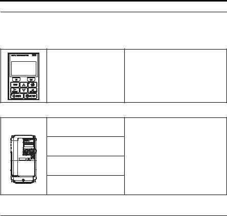
4 Option Components
Option
B |
D |
|
A |
S / N : J007XE273710001 |
E |
|
|
|
C |
|
|
|
|
D |
F
A |
– LCD Display |
D |
– Installation Mounting Holes |
B – ALARM (ALM) LED |
E |
– Nameplate <1> |
|
C |
– Keys |
F |
– Communication Cable Connector |
<1> REV: Display option version; PRG: Language data.
Figure 1 Option Components
12 |
YASKAWA ELECTRIC TOBP C730600 29G 1000-Series Option JVOP-180 Installation Manual |
4 Option Components
Keys
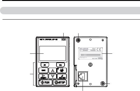
Refer to Figure 2 and Table 6 for details on key names and functions.
DIGITAL OPERATOR JVOP-180 |
ALM |
1
|
|
|
|
|
|
|
|
|
F1 |
|
|
F2 |
11 |
|||||
|
|
2 |
|
|
|
|
ESC |
|
|
LO |
|
|
9 |
|||||
|
|
|
|
|
|
|
|
RE |
|
|
||||||||
|
|
|
|
|
|
|
|
|
|
|||||||||
|
|
3 |
|
|
|
|
RESET |
|
|
|
|
|
|
|
8 |
|||
|
|
|
|
|
|
|
|
|
ENTER |
|
||||||||
|
|
10 |
|
|
|
|
|
|
RUN |
|
|
|
STOP |
|
|
|
||
|
|
|
|
|
|
|
|
|
|
|
|
|
|
|||||
|
|
|
|
|
|
|
|
|
|
|
|
|
|
|
||||
|
|
|
|
|
|
|
|
|
|
|
|
|
|
|||||
|
|
|
|
|
|
|
|
|
|
|
|
|
|
|
|
|
|
|
|
|
|
4 |
5 |
6 |
7 |
|
|
|
|
||||||||
|
|
|
|
|
|
|
Figure 2 Keys |
|
|
|
||||||||
|
|
Table 6 Key Names and Functions |
||||||||||||||||
|
|
|
|
|
|
|
|
|
|
|
|
|
|
|
|
|
|
|
No. |
Key |
Name |
|
|
|
|
|
|
|
|
|
|
|
|
|
Function |
||
|
F1 |
|
The functions assigned to F1 and F2 vary depending on the menu that is |
|||||||||||||||
|
Function Key |
currently displayed. The name of each function appears in the lower half |
||||||||||||||||
1 |
|
of the display window. |
|
|
|
|||||||||||||
|
(F1, F2) |
|
|
|
|
|
|
|
|
|
|
|
|
|
|
|
|
|
|
|
For a description of functions assigned to the F1 and F2 keys, Refer to |
||||||||||||||||
|
F2 |
|
||||||||||||||||
|
|
LCD Display on page 18. |
|
|
|
|||||||||||||
|
|
|
|
|
|
|||||||||||||
•Returns to the previous display.
•Moves the cursor one space to the left.
2 |
ESC Key |
• Pressing and holding this button will return to the following display: |
|
Drive: Frequency Reference |
|||
|
|
||
|
|
Converter: DC Bus Voltage Reference |
|
|
|
Regenerative unit: DC Bus Voltage |
|
3 |
RESET Key |
• Moves the cursor to the right. |
|
• Resets the unit to clear a fault situation. |
|||
|
|
YASKAWA ELECTRIC TOBP C730600 29G 1000-Series Option JVOP-180 Installation Manual |
13 |

4 Option Components
No. |
Key |
Name |
Function |
||||
4 |
|
|
|
|
RUN |
RUN Key |
Starts the unit and motor. |
|
|
|
|
|
|
|
|
|
|
|
|
|
|
|
|
5 |
|
|
|
|
|
Up Arrow Key |
Scrolls up to display the next item, selects parameter numbers and |
|
|
|
|
|
increments setting values. |
||
|
|
|
|
|
|
|
|
6 |
|
|
|
|
|
Down Arrow |
Scrolls down to display the previous item, selects parameter numbers and |
|
|
|
|
|
Key |
decrements setting values. |
|
|
|
|
|
|
|
||
|
|
|
|
|
|
|
|
|
|
|
|
|
|
|
Stops unit operation. |
7 |
|
|
|
|
|
STOP Key |
Note: The STOP key can be enabled or disabled when operating from the |
|
|
|
|
STOP |
|||
|
|
|
|
|
|
|
|
|
|
|
|
|
|
|
external terminal or network communications by setting parameter o2-02. |
8 |
|
|
|
|
|
ENTER Key |
• Enters parameter values and settings. |
|
|
|
|
|
• Selects a menu item to move between displays. |
||
|
|
|
|
|
|
|
|
|
|
|
|
|
|
|
|
|
|
|
|
|
|
|
Switches unit control between the operator (LOCAL) and an external |
|
|
|
|
|
|
|
source (REMOTE) for the Run command and frequency reference. |
9 |
|
|
|
|
|
LO/RE |
Note: The LOCAL/REMOTE key is only effective when the unit is |
|
|
|
|
|
Selection Key |
||
|
|
|
|
|
|
stopped in Drive Mode. As a safety precaution, it is possible to disable the |
|
|
|
|
|
|
|
|
|
|
|
|
|
|
|
|
LO/RE Selection Key by setting parameter o2-01 (LOCAL/REMOTE |
|
|
|
|
|
|
|
Key Function Selection) to 0 (disabled). |
10 |
|
|
|
|
|
RUN Light |
Illuminated during an operation. |
|
|
|
|
|
Refer to Option LED Status Indicators on page 15 for details. |
||
|
|
|
|
|
|
|
|
|
|
|
|
|
|
|
|
11 |
|
|
LO |
LO/RE Light |
Illuminated while the option is selected to run the unit (LOCAL mode). |
||
|
|
|
RE |
|
|
||
|
|
|
|
|
|
|
|
14 |
YASKAWA ELECTRIC TOBP C730600 29G 1000-Series Option JVOP-180 Installation Manual |

4 Option Components
Option LED Status Indicators
■Connecting the Option to A1000 or V1000
Table 7 LED Status and Meaning
LED |
Illuminated |
|
Flashing <1> |
Flashing Quickly <1> |
|
Off |
||||||||
|
When the option is |
|
|
|
|
|
|
|
|
When a device other |
||||
|
|
|
|
|
|
|
|
|
than the option is |
|||||
|
selected for Run |
|
|
|
|
|
|
|
|
|||||
LO |
|
|
|
|
|
|
|
|
selected for Run |
|||||
command and |
|
|
|
– |
|
|
|
– |
||||||
|
|
|
|
|
|
command and |
||||||||
RE |
frequency reference |
|
|
|
|
|
|
|
|
|||||
|
|
|
|
|
|
|
|
|
frequency reference |
|||||
|
control (LOCAL). |
|
|
|
|
|
|
|
|
|||||
|
|
|
|
|
|
|
|
|
control (REMOTE). |
|||||
|
|
|
|
|
|
|
|
|
|
|
|
|||
|
|
|
|
• |
During deceleration to |
• |
During deceleration |
|
|
|
||||
|
|
|
|
|
stop. |
|
when a Fast Stop |
|
|
|
||||
|
|
|
|
|
|
command was |
|
|
|
|||||
|
During run. |
• |
When a Run |
|
|
|
|
|||||||
RUN |
|
entered. |
During stop. |
|||||||||||
|
command is input and |
|
||||||||||||
|
|
|
|
• |
During stop by |
|
|
|
||||||
|
|
|
|
|
|
|
|
|||||||
|
|
|
|
|
the frequency |
|
External Fault digital |
|
|
|
||||
|
|
|
|
|
reference is 0 Hz. |
|
|
|
|
|||||
|
|
|
|
|
|
input. |
|
|
|
|||||
|
|
|
|
|
|
|
|
|
|
|
|
|||
Examples |
|
|
|
|
|
|
|
|
|
|
|
|
|
|
|
|
|
|
|
|
|
|
|
|
|
|
|
|
|
|
|
|
|
|
|
|
|
|
|
|
|
|
|
|
|
|
|
|
|
|
|
|
|
|
|
|
|
|
|
<1> Refer to Figure 3 for the difference between “flashing” and “flashing quickly”.
|
|
|
|
|
|
|
1 s |
|
|
|
|
|
|
|
|
|
|
|
|
|
|
|
|
||
|
|
|
|
|
|
|
|
|
|
|
|
|
|
|
|
|
|
|
|
|
|
||||
|
|
|
|
|
|
|
|
|
|
|
|
|
|
|
|
|
|
|
|
|
|
|
|
|
|
|
|
|
|
|
ON |
|
|
|
|
|
ON |
|
|
|
|
|
|||||||||
|
|
Flashing |
|
|
|
|
|
|
|
|
|
|
|
|
|
|
|
|
|
|
|
|
|
|
|
|
|
|
|
|
|
|
|
|
|
|
|
|
|
|
|
|
|
|
|
|
|
|
|||
|
|
|
|
|
|
|
|
|
|
|
|
|
|
|
|
|
|
|
|
|
|
|
|
|
|
|
|
|
|
ON |
|
ON |
|
|
|
|
|
ON |
|
|
|
ON |
|
|
|
|
|
|
|
|
|
|
|
Flashing |
|
|
|
|
|
|
|
|
|
|
|
|
|
|
|
|
|
|
|
|
|
|
|
|
|
|
|
|
|
|
|
|
|
|
|
|
|
|
|
|
|
|
|
|
|
|
|||
|
|
quickly |
|
|
|
|
|
|
|
|
|
|
|
|
|
|
|
|
|
|
|
|
|
|
|
|
|
|
|
|
|
|
Figure 3 RUN LED Status |
|
|
|
|
|
|
|
|
|
|
|
|
|
|||||
Drive output frequency |
|
|
|
|
|
RUN |
|
|
|
|
|
|
|
|
|
RUN STOP |
|||||||||
|
|
RUN / |
STOP |
During stop |
|
STOP |
|||||||||||||||||||
|
|
|
6 Hz |
|
|
|
|
|
|
|
|
|
|
|
|
|
|
|
|
||||||
|
|
|
|
|
|
|
|
|
|
|
|
|
|
|
|
|
|
|
|||||||
Frequency setting |
0 Hz |
|
|
|
|
|
|
|
|
|
|
|
|
|
|
|
|
||||||||
|
|
|
|
|
|
|
|
|
|
|
|
|
|
|
|
|
|
|
|
|
|||||
RUN LED |
|
|
OFF |
|
ON |
|
|
|
|
|
|
|
OFF |
|
OFF |
|
|||||||||
|
|
|
|
|
|
|
|
|
|
|
|
||||||||||||||
|
|
|
|
|
|
|
|
|
|
|
|
|
|
|
|
|
|
|
|
|
|
|
|
||
|
|
|
|
|
|
|
|
|
|
|
|
|
|
|
|
|
Flashing |
|
|
|
|
||||
|
|
|
|
|
|
Figure 4 RUN LED and Drive Operation |
|
|
|
|
|||||||||||||||
YASKAWA ELECTRIC TOBP C730600 29G 1000-Series Option JVOP-180 Installation Manual |
15 |
||||||||||||||||||||||||

4 Option Components
■Connecting the Option to D1000
Table 8 LED Status and Meaning
LED |
Illuminated |
Flashing Quickly <1> |
|
|
Off |
||||
|
When the run command is |
|
|
|
When a device other than the |
||||
LO |
|
|
|
option is selected for Run |
|||||
selected from the LED |
|
|
– |
||||||
|
|
command and frequency reference |
|||||||
RE |
operator (LOCAL). |
|
|
|
|||||
|
|
|
|
control (REMOTE). |
|||||
|
|
|
|
|
|
|
|||
RUN |
During run. |
During stop by External Fault |
During stop. |
||||||
|
|
|
digital input. |
|
|
|
|||
Examples |
|
|
|
|
|
|
|
|
|
|
|
|
|
|
|
|
|
|
|
|
|
|
|
|
|
|
|
|
|
|
|
|
|
|
|
|
|
|
|
|
|
|
|
|
|
|
|
|
|
<1> Refer to Figure 5 for the difference between “flashing” and “flashing quickly”.
|
|
|
|
|
|
|
|
1 s |
|
|
|
|
|
|||
|
|
|
|
|
|
|
|
|
|
|
|
|
|
|
|
|
Flashing |
|
|
|
ON |
|
|
|
|
ON |
|
|
|||||
|
|
|
|
|
|
|
|
|
|
|
|
|
||||
|
|
|
|
|
|
|
|
|
|
|
|
|
||||
|
|
|
|
|
|
|
|
|
|
|
|
|
|
|
|
|
Flashing |
|
ON |
|
|
ON |
|
|
|
ON |
|
ON |
|
|
|
||
|
|
|
|
|
|
|
|
|
|
|
|
|
|
|||
quickly |
|
|
|
|
|
|
|
|
|
|
|
|||||
|
|
|
|
|
|
|
|
Figure 5 RUN LED Status |
|
|
|
|
|
|||
DC bus voltage reference |
|
|
|
|
|
|
|
|
|
|
|
|||||
DC bus voltage |
|
|
|
|
|
|
|
|
|
|
|
|||||
|
|
RUN / STOP |
|
|
RUN |
|
|
|
|
|
||||||
|
|
|
|
|
|
|
|
|
|
STOP |
|
|||||
|
|
|
|
|
|
|
|
|
|
|
||||||
|
|
|
|
|
|
|
|
|
|
|
|
|
||||
RUN LED |
|
OFF |
|
ON |
|
|
|
OFF |
|
|||||||
Figure 6 RUN LED and Converter Operation
16 |
YASKAWA ELECTRIC TOBP C730600 29G 1000-Series Option JVOP-180 Installation Manual |

4 Option Components
■Connecting the Option to R1000
Table 9 LED Status and Meaning
LED |
Illuminated |
Flashing Quickly <1> |
|
|
Off |
||||
|
When the run command is |
|
|
|
When a device other than the |
||||
LO |
|
|
|
option is selected for Run |
|||||
selected from the LED |
|
|
– |
||||||
|
|
command and frequency reference |
|||||||
RE |
operator (LOCAL). |
|
|
|
|||||
|
|
|
|
control (REMOTE). |
|||||
|
|
|
|
|
|
|
|||
RUN |
During run. |
During stop by External Fault |
During stop. |
||||||
|
|
|
digital input. |
|
|
|
|||
Examples |
|
|
|
|
|
|
|
|
|
|
|
|
|
|
|
|
|
|
|
|
|
|
|
|
|
|
|
|
|
|
|
|
|
|
|
|
|
|
|
|
|
|
|
|
|
|
|
|
|
<1> Refer to Figure 7 for the difference between “flashing” and “flashing quickly”.
|
|
|
|
|
|
|
|
|
1 s |
|
|
|
|
|
|||
|
|
|
|
|
|
|
|
|
|
|
|
|
|
|
|
|
|
Flashing |
|
|
|
ON |
|
|
|
|
ON |
|
|
||||||
|
|
|
|
|
|
|
|
|
|
|
|
|
|||||
|
|
|
|
|
|
|
|
|
|
|
|
|
|||||
|
|
|
|
|
|
|
|
|
|
|
|
|
|
|
|
|
|
Flashing |
|
|
ON |
|
|
ON |
|
|
|
ON |
|
ON |
|
|
|
||
|
|
|
|
|
|
|
|
|
|
|
|
|
|
|
|||
|
|
|
|
|
|
|
|
|
|
|
|
|
|
||||
quickly |
|
|
|
|
|
|
|
|
|
|
|
||||||
|
|
|
|
|
|
|
|
|
Figure 7 RUN LED Status |
|
|
|
|
|
|||
|
|
RUN / STOP |
|
|
RUN |
|
|
|
|
|
|||||||
|
|
|
|
|
|
|
|
|
|
STOP |
|
||||||
|
|
|
|
|
|
|
|
|
|
|
|||||||
|
|
|
|
|
|
|
|
|
|
|
|
|
|||||
|
|
|
|
|
|
|
|
|
|
|
|
|
|||||
|
|
|
|
|
|
|
|
|
|
|
|
||||||
RUN LED |
|
OFF |
|
ON |
|
|
|
OFF |
|
||||||||
Figure 8 RUN LED and Regenerative Unit Operation
YASKAWA ELECTRIC TOBP C730600 29G 1000-Series Option JVOP-180 Installation Manual |
17 |
4 Option Components
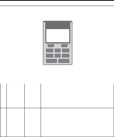
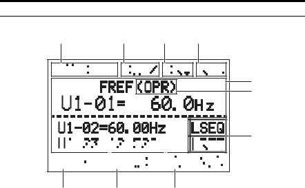
LCD Display
1 |
|
|
|
|
|
|
|
2 |
|
3 |
4 |
|
|
|
|
|
|
|
|
|
|
|
|
|
||||||||||||||||||||||||||||||||||||||||||
|
|
|
|
|
|
|
|
|
|
|
|
|
|
|
|
|
|
|
|
|
|
|
|
|
|
|
|
|
|
|
|
|
|
|
|
|
|
|
|
|
|
|
|
|
|
|
|
|
|
|
|
|
|
|
|
|
|
|
|
|
|
|
|
|
|
|
5
6
7
|
|
|
|
|
|
|
|
|
|
|
|
|
|
|
|
|
|
|
|
|
|
|
|
|
|
|
|
|
|
|
|
|
|
|
|
|
|
|
|
|
|
|
|
|
|
|
|
|
|
|
|
|
|
|
|
|
|
|
|
|
|
|
|
|
|
|
|
|
|
|
|
|
|
|
|
|
|
|
|
|
|
|
|
|
|
|
|
|
|
|
|
|
|
|
|
|
|
|
|
|
|
|
|
|
|
|
|
|
|
|
|
|
|
|
|
|
|
|
|
|
|
|
|
|
|
|
|
|
|
|
|
|
|
|
|
|
8 |
|
|
|
|
|
|
|
|
|
|
|
|
|
9 |
10 |
|
|
|
|
|
|
|
|
|
|
|
|
|
|
|
|
|
|
|
|
|
|
|
|
|||||||||||||||||||||||||||
|
|
|
|
|
|
|
|
|
|
|
|
|
|
|
|
|
|
|
|
|
|
|
Figure 9 LCD Display |
||||||||||||||||||||||||||||||||||||||||||||
|
|
|
|
|
|
|
|
|
|
|
|
|
|
|
|
Table 10 Display and Contents |
|||||||||||||||||||||||||||||||||||||||||||||||||||
|
|
|
|
|
|
|
|
|
|
|
|
|
|
|
|
|
|
|
|
|
|
|
|
|
|
|
|
|
|
|
|
|
|
|
|
|
|
|
|
|
|
|
|
|
|
|
|
|
|
|
|
|
|
|
|
|
|
|
|
|
|
|
|
|
|
|
|
No. |
Name |
|
|
|
Display |
|
|
|
|
|
|
|
|
|
|
|
|
|
|
|
|
|
|
|
|
|
|
|
|
|
|
|
|
|
|
|
|
Content |
|||||||||||||||||||||||||||||
|
|
|
|
|
|
|
|
MODE |
Displayed when in Mode Selection. |
||||||||||||||||||||||||||||||||||||||||||||||||||||||||||
|
|
|
|
|
|
|
MONITR |
Displayed when in Monitor Mode. |
|||||||||||||||||||||||||||||||||||||||||||||||||||||||||||
1 |
Operation Mode |
|
|
|
VERIFY |
Indicates the Verify Menu. |
|||||||||||||||||||||||||||||||||||||||||||||||||||||||||||||
Menus |
|
|
|
PRMSET |
Displayed when in Parameter Setting Mode. |
||||||||||||||||||||||||||||||||||||||||||||||||||||||||||||||
|
|
|
|
||||||||||||||||||||||||||||||||||||||||||||||||||||||||||||||||
|
|
|
|
|
|
|
|
A.TUNE |
Displayed during Auto-Tuning. |
||||||||||||||||||||||||||||||||||||||||||||||||||||||||||
|
|
|
|
|
|
|
|
SETUP |
Displayed when in Setup Mode. |
||||||||||||||||||||||||||||||||||||||||||||||||||||||||||
|
DriveWorksEZ |
|
|
|
DWEZ |
Displayed when the DriveWorksEZ is set to enable. |
|||||||||||||||||||||||||||||||||||||||||||||||||||||||||||||
2 |
Function Selection |
|
|
|
|||||||||||||||||||||||||||||||||||||||||||||||||||||||||||||||
|
|
|
(A1-07 = 1 or 2) |
||||||||||||||||||||||||||||||||||||||||||||||||||||||||||||||||
|
<1> |
|
|
|
|
|
|
|
|
|
|
|
|
|
|
|
|
||||||||||||||||||||||||||||||||||||||||||||||||||
|
|
|
|
|
|
|
|
|
|
|
|
|
|
|
|
|
|
|
|
|
|
|
|
|
|
|
|
|
|
|
|
|
|
|
|
|
|
|
|
|
|
|
|
|
|
|
|
|
|
|
|
|
|
|
|
|
|
|
|
|
|
|
|
|
|
|
|
|
|
|
|
|
|
|
|
|
|
|
|
|
|
|
|
|
|
|
|
|
|
|
|
|
|
|
|
|
|
|
|
|
|
|
|
|
|
|
|
|
|
|
|
|
|
|
|
|
|
|
|
|
|
|
|
|
|
|
|
|
|
|
|
|
|
|
|
3 |
Mode Display Area |
|
|
|
|
|
DRV |
Displayed when in Drive Mode. |
|||||||||||||||||||||||||||||||||||||||||||||||||||||||||||
|
|
|
|
|
PRG |
Displayed when in Programming Mode. |
|||||||||||||||||||||||||||||||||||||||||||||||||||||||||||||
|
|
|
|
|
|
|
|
|
|
||||||||||||||||||||||||||||||||||||||||||||||||||||||||||
4 |
Ready |
|
|
|
|
|
Rdy |
Indicates the unit is ready to run. |
|||||||||||||||||||||||||||||||||||||||||||||||||||||||||||
5 |
Data Display |
|
|
|
|
|
|
– |
Displays specific data and operation data. |
||||||||||||||||||||||||||||||||||||||||||||||||||||||||||
18 |
YASKAWA ELECTRIC TOBP C730600 29G 1000-Series Option JVOP-180 Installation Manual |
Loading...