


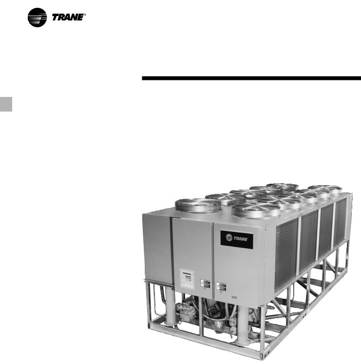
Air-Cooled Series R™
Rotary Liquid Chiller
Model RTAA 70 to 125 Tons
Built for the Industrial and Commercial Markets
August 2002 |
RLC-PRC016-EN |
Features and
Benefits
You…
Like its chillers, Trane wants its relationships with customers to last. Trane is interested in maintaining long term, loyal relationships. This perspective means the point in time that a customer purchases a chiller is the beginning of a relationship, not the end. Your business is important, but your satisfaction is paramount.
Designed by Customers….
Trane’s RTAA 70-125 was designed with the end user’s requirements in mind. Reliability, efficiency, sound, and physical size were primary design concerns in expanding the RTAA product line down to 70 tons. The result is a reliable chiller that will help you achieve your bottom line goals.
2© 2002 American Standard Inc. All rights reserved. |
RLC-PRC016-EN |
Contents
Features and Benefits |
2 |
Model Number Description |
|
13 |
|
General Data |
|
14 |
|
Selection Procedure |
|
15 |
|
Application Considerations |
|
16 |
|
Performance Adjustment Factors |
|
20 |
|
Performance Data |
|
22 |
|
Electrical Data |
|
29 |
|
Jobsite Connections |
|
30 |
|
Controls |
|
32 |
|
Dimensional Data |
|
40 |
|
Weights |
|
41 |
|
Options |
|
42 |
|
Typical Wiring Diagrams |
|
43 |
|
Features Summary |
|
45 |
|
Mechanical Specifications |
|
46 |
|
|
|
The standard ARI rating condition (54/44°F and 95°F) and IPLV are ARI certified. All other ratings, including the following, are outside the scope of the certification program and are excluded:
• Glycol. Water Chiller Systems Business Unit
•50 Hz.
•Remote evaporator models.
RLC-PRC016-EN |
3 |
Features and
Benefits
Improvements
The RTAA 70-125 offers the same high reliability of its larger predecessor coupled with lowered sound levels, increased energy efficiency, and reduced physical footprint, all due to its advanced design, low speed/direct drive compressor and proven Series R™ performance.
Some of the major advantages of the Model RTAA 70-125 vs its larger predecessor are:
•Higher energy efficiency
•Lower sound levels
•Smaller physical footprint
The Series R™ Model RTAA 70-125 is an industrial grade design built for both the industrial and commercial markets. It is ideal for schools, hospitals, retailers, office buildings, Internet service providers and industrials.
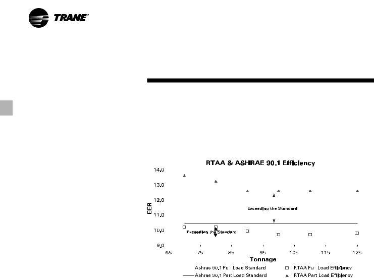
ASHRAE Standard 90.1 and RTAA 70125 World Class Energy Efficiency…
The importance of energy efficiency cannot be understated. Fortunately, ASHRAE has created a guideline emphasizing its importance. Nonetheless, energy is often dismissed as an operational cost over which the owner has little control. That perception results in missed opportunities for energy efficiency, reduced utility bills, and higher profits. Lower utility bills directly affect profitability. Every dollar saved in energy goes directly to the bottom line. Trane’s RTAA 70-125 is one way to maximize your profits.
ASHRAE Standard 90.1 & Executive Order - New technology applied to the design, controls, and manufacturing have created superior efficiency levels in the RTAA 70-125 that are unmatched in the industry. All Trane air-cooled chillers meet the new efficiency levels mandated by ASHRAE Standard 90.1. This new standard requires higher efficiencies than past technologies can deliver. The US Federal Government has adopted standard 90.1 and, in some cases, requires even higher efficiencies. Federal Executive Order mandates energy consuming devices procured must be in the top 25% of their class or
be at least 10% better than any product standard for that product. In the case of chillers, that product standard is ASHRAE 90.1. Trane’s RTAA 70-125 meets and exceeds the efficiency requirements of 90.1, with some units meeting the “stretch goals” of Executive Order.
|
|
|
|
|
|
|
|
|
|
|
|
|
|
|
|
|
|
|
|
|
|
|
|
|
|
|
|
|
|
|
|
|
|
|
|
|
|
|
|
|
|
|
|
|
|
|
|
|
|
|
|
|
|
|
|
|
|
|
|
|
|
|
|
|
|
|
|
|
|
|
|
|
|
|
|
|
|
|
|
|
|
|
|
|
|
|
|
|
|
|
|
|
|
|
|
|
|
|
|
|
|
|
|
|
|
|
|
|
|
|
|
|
|
|
|
|
|
|
|
|
|
|
|
|
|
|
|
|
|
|
|
|
|
|
|
|
|
|
|
|
|
|
|
|
|
|
|
|
|
|
|
|
|
|
|
|
|
|
|
|
|
|
|
|
|
|
|
|
|
|
|
|
|
|
|
|
|
|
|
|
|
|
|
|
|
|
|
|
|
|
|
|
|
|
|
|
|
|
|
|
|
|
|
|
|
|
|
|
|
|
|
|
|
|
|
|
|
|
|
|
|
|
|
|
|
|
|
|
|
|
|
|
|
|
|
|
|
|
|
|
|
|
|
|
|
|
|
|
|
|
|
|
|
|
|
|
|
|
|
|
|
|
|
|
|
|
|
|
|
|
|
|
|
|
|
|
|
|
|
|
|
|
|
|
|
|
|
|
|
|
|
|
|
|
|
|
|
|
|
|
|
|
|
|
|
|
|
|
|
|
|
|
|
|
|
|
|
|
|
|
|
|
|
|
|
|
|
|
|
|
|
|
|
|
|
|
|
|
|
|
|
|
|
|
|
|
|
|
|
|
|
|
|
|
|
|
|
|
|
|
|
|
|
|
|
|
|
Risk. The US Federal Government has |
setpoint, potentially eliminating the need |
|||||||||||||||||||||
adopted ASHRAE 90.1, and it’s expected |
for external considerations to maintain |
|||||||||||||||||||||
to be adopted domestically, if not |
temperatures. Reciprocating and screw |
|||||||||||||||||||||
globally, in the future. Domestic |
chillers with stepped capacity control do |
|||||||||||||||||||||
acceptance has already begun. Make |
well to maintain chilled water |
|||||||||||||||||||||
sure that your chillers as well as your |
temperatures within 2ºF of setpoint. |
|||||||||||||||||||||
entire HVAC system complies, or you |
Stepped control also results in |
|||||||||||||||||||||
may be caught retrofitting your project |
overcooling or undercooling your space |
|||||||||||||||||||||
with new equipment and paying extra |
because rarely does the capacity of the |
|||||||||||||||||||||
design dollars if the code is adopted |
machine match the building load. The |
|||||||||||||||||||||
during construction. |
result can be 10% higher energy bills. |
|||||||||||||||||||||
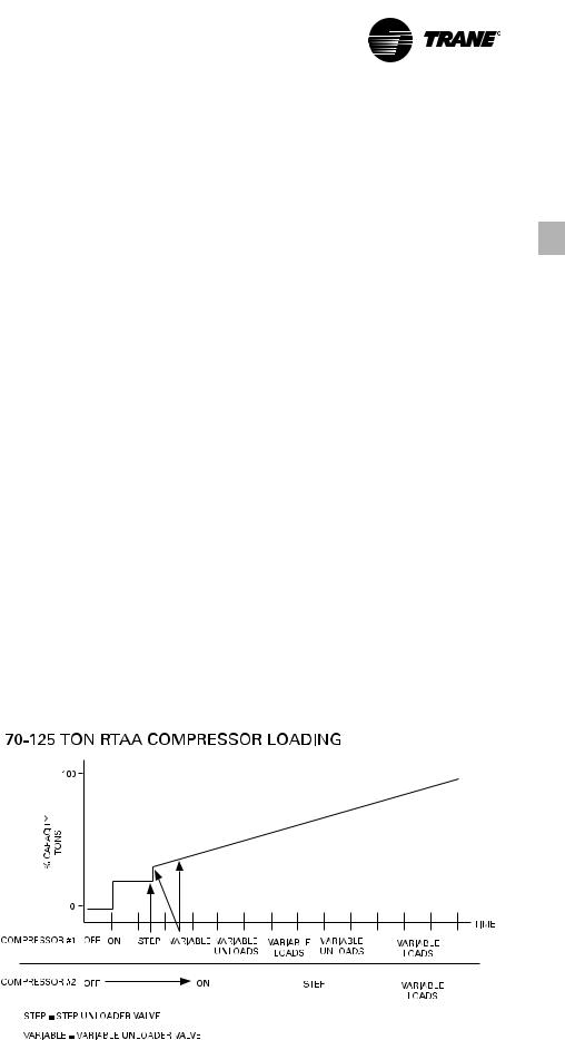
Precise Capacity Control. Trane’s |
Trane’s RTAA optimizes the part load |
|||||||||||||||||||||
performance of your machine for energy |
||||||||||||||||||||||
patented unloading system allows the |
||||||||||||||||||||||
efficiency, precise temperature control |
||||||||||||||||||||||
compressor to modulate infinitely and |
||||||||||||||||||||||
for all modes of operation, and your |
||||||||||||||||||||||
exactly match building loads. At the |
||||||||||||||||||||||
personal comfort regardless of changing |
||||||||||||||||||||||
same time chilled water temperatures |
||||||||||||||||||||||
conditions. |
||||||||||||||||||||||
will be maintained within +/- 1/2ºF of |
||||||||||||||||||||||
|
|
|
|
|
|
|
|
|
|
|
||||||||||||
4 |
RLC-PRC016-EN |
Features and
Benefits
Excellent Reliability
A building environment is expected to be comfortable. When it is, no one says a word. If it’s not… that’s a different story. The same is true with chillers. No one ever talks about chillers, yet alone compressors, until they fail, and tenets are uncomfortable and productivity is lost. Trane’s helical rotary compressors have a first year reliability rate of over 99%, which means our chillers stay running when you need them.
Screw compressors were designed to replace the inherent design flaws of a reciprocating compressor. Trane’s helical rotary compressor has successfully achieved this goal, proven by the over 99% reliability rating of our compressor in the first year of operation. A good design like Trane’s should maintain this level of reliability for several years of chiller operation. Not all screw compressors maintain a high reliability and Trane is the only manufacturer that will publish a reliability number. The point is to make sure that you are getting a reliable screw chiller design so that you don’t end up with the downtime and lost earnings that the industry is trying to
avoid by getting away from reciprocating technology.
Fewer moving parts. Trane’s helical rotary compressors have only two major rotating parts: the male and female rotor. A reciprocating compressor can have more than 15 times that number of critical parts. Multiples of pistons, valves, crankshafts, and connecting rods in a reciprocating unit all represent different failure paths for the compressor. In fact, reciprocating compressors can easily have a failure rate four times that of a helical rotor. Combine this with two to three reciprocating compressors for each helical rotary compressor on chillers of equal tonnage, and statistics tell you it’s
a matter of time before you lose a reciprocating compressor.
Robust parts. Helical rotary compressors are precisely machined using state of the art processes from solid metal bar stock. Tolerances are maintained within a micron or less than a tenth of the diameter of a human hair. The resulting compressor is a robust yet highly sophisticated assembly capable of ingesting liquid refrigerant without risk of damage. Contrast this to a reciprocating compressor, which can be destroyed by a single slug of liquid.
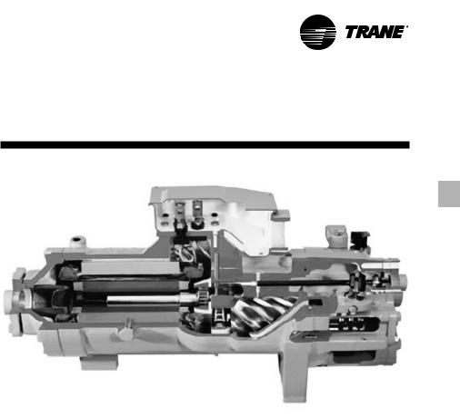
Series R™ Compressor Highlights
•Direct-drive, low speed for high efficiency and reliability.
•Simple design with only four moving parts, resulting in high reliability and low maintenance.
•Field serviceable compressor for easy maintenance.
•Precise rotor tip clearance for optimal efficiency.
•Suction gas-cooled motor, resulting in lower operating temperatures for increased motor life, and giving the capability for:
•Five-minute start-to-start/two minute stop-to-start capability, which allows for closer water loop temperature control.
RLC-PRC016-EN |
5 |

Features and
Benefits
RTAA 70-125 Chiller Highlights
•High Reliability, with over 99% compressor reliability rate in the first year of operation, and Adaptive Controls to keep the chiller on line producing cold water during adverse conditions.
•High Efficiency (all units exceed ASHRAE 90.1 efficiency standard).
•Low sound levels.
•Small footprint, with smallest required application space (operating footprint) in the industry.
•Years of research, testing, and successful applications. The Trane helical rotary compressor has amassed thousands of hours of testing, much of it at severe operating conditions. Not to mention the successful application of RTAA chillers for over 11 years, with a developed reputation as the industry standard.
•Trouble free startup through factory testing of compressor and completed chiller and factory installation of chiller accessories.
•+/- ½°F leaving water temperature control, resulting from PID feedforward controls, and linear load matching, also allowing for 10% flow rate change per minute while maintaining ± ½°F leaving water temperature control.
Trane helical rotary screw compressor component parts versus reciprocating compressor components.
6 |
RLC-PRC016-EN |
Features and |
Optimum |
Benefits |
Efficiencies |
|
|
|
|
Superior Full Load Efficiency
Precise Rotor Tip Clearances
Higher energy efficiency in a helical rotary compressor is obtained by reducing the rotor tip clearances. This reduces the leakage between high and low pressure cavities during compression. Precise rotor tip clearance is achieved with the latest manufacturing and machining technology. Trane is the first helical rotary compressor manufacturer to electronically check compressor parts machining accuracy as part of the standard production process.
Optimized Compressor Parts Profiles
Rotor and slide valves are unique designs, optimized for the air conditioning application. The rotors are designed for the pressure ranges in the air conditioning application. The unloader valve has a unique profile that resulted from computer performance modeling in typical part-load situations.
Advanced Heat Transfer Surfaces
Condenser and evaporator tubes use the latest heat transfer technology for increased efficiency.
Great Part Load Efficiency
With Trane Helical Rotary
Screw Compressors and
Electronic Expansion Valve
Trane Helical Rotary Screw Compressor Means Superior Part Load Performance
The air-cooled Series R™ chiller has great part-load performance. The combination patented unloading system on the “general purpose” compressor utilizes the variable unloading valve for the majority of the unloading function similar to that of the slide valve. The “general purpose” compressor also uses a step unloader valve which is a single unloading step to achieve the minimum unloading point of the compressor. The result of both of these designs is optimized part-load performance far superior to single reciprocating compressors.
RLC-PRC016-EN |
7 |
Features and
Benefits
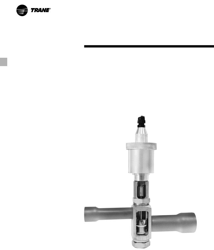
Electronic Expansion Valve
When coupled with Trane’s Adaptive Control™ microprocessor, our electronic expansion valve significantly improves part-load performance of the Series R™ chiller by minimizing superheat in the evaporator and allowing the chiller to run at reduced condensing temperatures. Chillers which use conventional TXV’s must run at higher head pressures and consume more power than necessary at part-loads. Additionally, the electronic expansion valve and its controls allow much better stability and control over dynamic load and head changes. Under these conditions a conventional TXV may never achieve control stability and extended periods of TXV “hunting” and liquid slugging are common.
Capacity Control and Load Matching
Infinitely variable compressor modulation allows the compressor capacity to exactly match the building cooling load. Reciprocating and screw chillers that rely on stepped capacity control must run at a capacity equal to or greater than the load. Much of this excess capacity is lost because overcooling goes toward building latent heat removal, causing the building to be dried beyond normal comfort requirements. The result is an increase in chiller energy costs, particularly at the part-load conditions at which the chiller operates most of the time.
PID Chilled Water Setpoint
Control Through Slide Valve
Modulation
Maintain Chilled Water Supply Within
± 1/2°F of Setpoint
Chillers that have step capacity control typically can only maintain water temperature to around ± 2°F. With the air-cooled Series R™ chiller, maintaining temperature control has never been so accurate.
Reduce Compressor Cycling
Modulating capacity control offers better compressor reliability. Compressor cycling, typical of reciprocating compressors, will decrease compressor component life. Parts like motors and valves do not stand up well to excessive compressor cycling.
Cutaway view of Trane’s electronic expansion valve.
8 |
RLC-PRC016-EN |
Features and
Benefits
Trouble-Free Installation,
Start-Up and Operation
Adaptive Control™ Microprocessor
The RTAA 70-125 chiller offers advanced microprocessor control and features the Adaptive Control microprocessor. So what is the Adaptive Control microprocessor? Adaptive Control means the Unit Control Module (UCM) directly senses the control variables that govern operation of the chiller: motor current draw, evaporator temperature, condenser temperature, etc.
When any of the variables approaches a limit condition where the unit may be damaged or shut down on a safety, the UCM takes corrective action to avoid
shutdown and keep the chiller operating. It does this through combined actions of compressor slide valve modulation, electronic expansion valve modulation and fan staging. Additionally, the UCM optimizes total unit power consumption during normal operating conditions. No other chiller control system in the marketplace duplicates this performance.
The End Of Most Nuisance Trip-Outs And Unnecessary Service Calls?
Unnecessary service calls and unhappy tenants are reduced. Only when the UCM has exhausted the corrective actions it can take and the unit is still violating an operating limit will the unit shut down. CONTROLS ON OTHER
CHILLERS TYPICALLY SHUT DOWN THE CHILLER, QUITE PROBABLY JUST WHEN IT IS NEEDED THE MOST.
For example:
A typical five-year-old chiller with dirty coils might trip-out on high pressure cutout on a 100°F day in August. A hot day is just when comfort cooling is needed the most. In contrast, the aircooled Series R™ chiller with an Adaptive Control microprocessor will stage fans on, modulate electronic expansion valve, and modulate slide valve as it approaches a high pressure cutout. Thereby KEEPING THE CHILLER ONLINE JUST WHEN YOU NEED IT THE MOST.
RLC-PRC016-EN |
9 |
Features and
Benefits
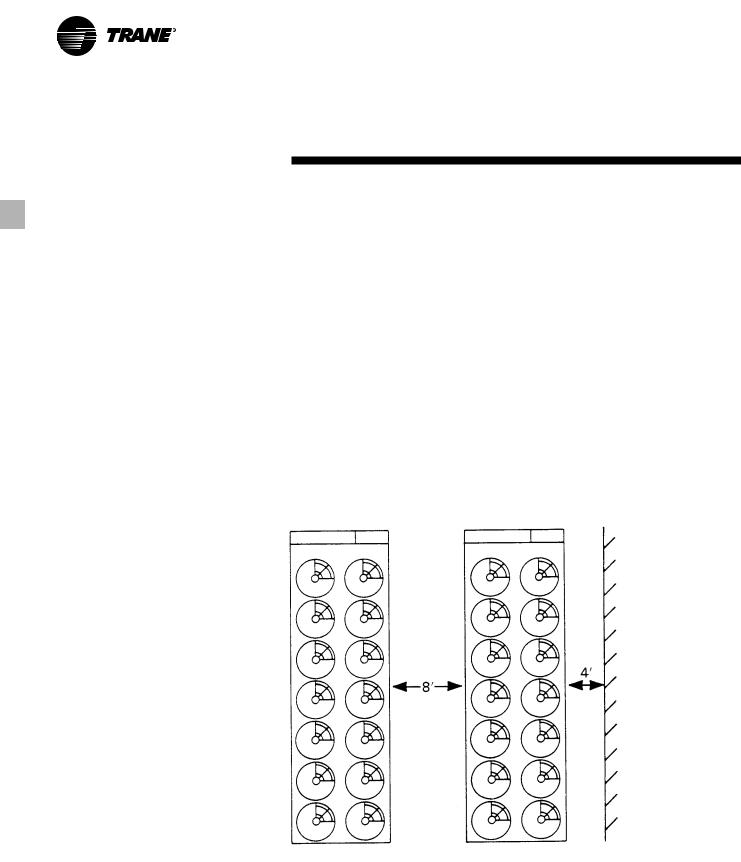
Close Spacing Of Chiller
The air-cooled Series R™ chiller has the tightest recommended side clearance in the industry, four feet, but that is not all. In situations where equipment must be installed with less clearance than recommended, such as frequently occurs in retrofit and rooftop applications, restricted air flow is common. Conventional chillers may not work at all. However, the air-cooled Series R™ chiller with Adaptive Control™ microprocessor will simply make as much chilled water as it can given the actual installed conditions, stay on line during any unforeseen abnormal conditions, and optimize its performance. Consult your Trane sales engineer for more details.
Lower Service Expense
Nuisance service calls are avoided. When there is a real problem that must be corrected, the UCM’s extensive diagnostics help assure that the problem is quickly identified. Down time and service expense are minimized. And with the ability to communicate with the Trane Integrated Comfort™ system or a remote display panel, service problems can be identified and diagnosed remote to the installation.
Factory Testing Means Trouble-Free Start-Up
All air-cooled Series R™ chillers are given a complete functional test at the factory. This computer-based test program completely checks the sensors, wiring, electrical components, microprocessor function, communication capability, expansion valve performance and fans. In addition, each compressor is run tested to verify capacity and power consumption. The end result of this test program is that the chiller arrives at the jobsite fully tested and ready to go to work.
Factory Installed And Tested Controls/ Options Speed Installation
All Series R™ chiller options, including control power transformer, starter disconnect, low ambient control, ambient temperature sensor, low ambient lockout, communication interface and ice making controls are factory installed and tested. Some manufacturers send options in pieces to be field installed. With Trane, the customer saves on installation expense and has assurance that ALL chiller controls/options have been tested and will function as expected.
10 |
RLC-PRC016-EN |
Features and
Benefits
Superior Control
Unit Control Module
Trane’s Adaptive Control™ microprocessor control system enhances the air-cooled Series R™ chiller by providing the very latest chiller control technology.
State-of-the-Art Equipment
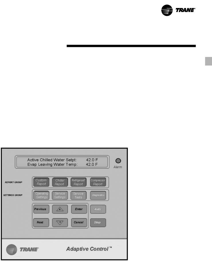
The 70 to 125 ton air-cooled chillers offer the exclusive Trane Adaptive Control logic with the Clear Language Display (UCM). The Clear Language Display has various functions that allow the operator to read unit information and adjust setpoints. The Clear Language Display panel has 16 keys, the readout screen is a two-line, 40 character liquid crystal with a backlight. The backlight allows the operator to read the display in low-light conditions.
Unit Control Module Features
Equal Compressor Sequencing
Trane maximizes both compressor and motor life by equalizing both the number of starts and the operating hours. The UCM will start the compressor with the least number of starts and turn off the compressor with the most operating hours. Conventional “auto” lead-lag control will equalize starts, but running hours will typically be unequal. Equalizing both starts and running hours will provide equal compressor wear.
Internal “Built-In” Chiller Flow Protection
The UCM automatically detects a no waterflow condition. An external flow switch is not required, which lowers costs versus typical chillers. Built-in flow protection also eliminates nuisance flow switch problems.
Remote Clear Language Display Panel for 70 to 125-ton air-cooled chillers.
RLC-PRC016-EN |
11 |
Features and
Benefits
Easy Chiller System Logging
The UCM displays data required to log the chiller system. The following information is available either as standard or as an option with the AirCooled Series R™ Chiller microprocessor:
•Entering and leaving chilled water temperatures
•Ambient air temperature
•Evaporator and condenser refrigerant temperatures and pressures
•Compressor suction temperature
•Percent RLA for each compressor
•Percent line voltage
•Compressor starts and running hours
•Active setpoints: chilled water setpoint current limit setpoint ice termination setpoint
low ambient lockout setpoint
•Over 90 diagnostic and operating conditions
•Part failure diagnostics: water temperature sensors
refrigerant temperature sensors compressor contactors
Remote Display Panel
Trane air-cooled Series R™ 70-125 ton chillers are available with a twisted pair connection to an optional remote display panel. Chiller operation can be controlled similarly to the control interface on the chiller itself. Through a twisted pair of wires the unit can be turned on or off, change the chilled water setpoint, and display over 90 operating and diagnostic conditions. The remote display panel can be mounted indoors so access to chiller information is just steps away, eliminating any need to go outdoors or on the roof.
The clear language display for chiller sizes of 70-125 tons has the ability to control multiple units. In a multiple unit configuration, the Remote Clear Language Display Panel has the capability to communicate with up to four units. Each unit requires a separate communication link with the Remote Display Panel.
Easy Interface To The Building Management System
Controlling the air-cooled Series R™ chiller with building management systems is state-of-the-art yet simple.
Chiller inputs include:
•Chiller enable/disable
•Circuit enable/disable
•Chilled water setpoint
•Current limit setpoint
•Ice making enable
Chiller outputs include:
•Compressor running indication
•Alarm indication (CKt 1/CKt2)
•Maximum capacity
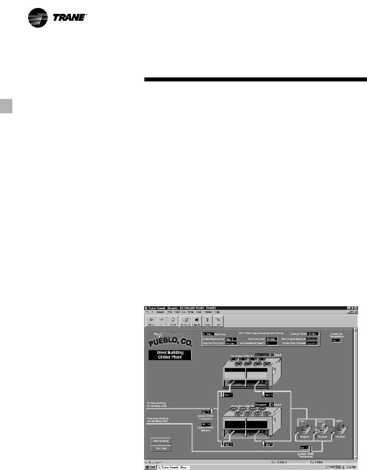
Trane Chiller Plant Manager/ICS
The Tracer™ Chiller Plant Manager Building Management System provides building automation and energy management functions through standalone control. The Chiller Plant Manager is capable of monitoring and controlling your entire chiller plant system.
Application software available:
•Time-of-day scheduling
•Duty cycle
•Demand limiting
•Chiller sequencing
•Process control language
•Boolean processing
•Zone control
•Reports and logs
•Custom messages
•Run time and maintenance
•Trend log
•Totalizing
•PID control loops
And of course, Trane’s Chiller Plant Manager Panel can be used on a standalone basis or tied into a complete building automation system.
12 |
RLC-PRC016-EN |
Model Number
Description
Model Nomenclature Digit Number
1 2 3 4 5 6 7 8 9 10 11 12 13 14 15 16 17
70-125 Tons
Digits 1,2 — Unit Model
RT = Rotary Chiller
Digit 3 — Unit Type
A = Air Cooled
Digit 4 — Development Sequence
A = First Sequence
Digit 5, 6 & 7 — Nominal Capacity
070 = 70 tons
080 = 80 tons
090 = 90 tons
100 = 100 tons
110 = 110 tons
125 = 125 tons
Digit 8 — Unit Voltage
A = 200/60/3
C= 230/60/3
D= 380/60/3
4 = 460/60/3
5 = 575/60/3
S= Special
Digit 9 — Compressor Starter Type
Y = Y-Delta Closed Transition
X = X-Line (Across the Line)
S = Special
Digit 10, 11 — Design Sequence
** = Factory Input
Digit 12 — Evaporator Leaving Temperature
1= Standard 40 to 65°F
2= Low 0 to 39°F
3= Ice-Making 20 to 65°F
S = Special
Digit 13 — Condenser Coil Fin Material
A = Aluminum
S = Special
2 = Copper Fins
4 = CompleteCoat
Digit 14 — Agency Listing
0 = No Agency Listing
3 = C/UL Listing
Digit 15 — Control Interface
C= Deluxe without Communication
D= Deluxe with Communication
Digit 16 — Chilled Water Reset
0= No Chilled Water Reset
1= Based on Return Water Temperature
2= Based on Outside Air Temperature
Digit 17 — Miscellaneous Factory Installed
Options
A= Architectural Louvered Panels
B= Control Power Transformer
C= Convenience Outlet
D= Low Ambient Lockout Sensor
F= Mech. Disconnect Switch
G= Low Ambient Operation
K= Coil Protection
M= Access Guard
P= Circuit Breaker (Single Point Power)
Z= Circuit Breaker (Dual Point Power)
Field Installed Options
Q = Spring Isolators
N = Neoprene Isolators
R = Remote Display Panel
3 = 5 Year Compressor Warranty
8= Architectural Louvered Panels
9= Coil Protection
0 = Access Guard
J = Remote Evaporator
H = Sound Attenuator
RLC-PRC016-EN |
13 |

General Data
Table G-1 — General Data RTAA — 70-125 Ton
|
|
Size |
|
70 |
80 |
90 |
100 |
110 |
125 |
|
|
Compressor |
|
|
|
|
|
|
|
|
|
Quantity |
|
2 |
2 |
2 |
2 |
2 |
2 |
|
|
Nominal Size (1) |
(Tons) |
35/35 |
40/40 |
50/40 |
50/50 |
60/50 |
60/60 |
|
|
Evaporator |
|
|
|
|
|
|
|
|
|
Water Storage |
(Gallons) |
39.8 |
37.3 |
34.4 |
32.1 |
53.4 |
45.8 |
|
|
|
(Liters) |
150.6 |
143.1 |
130.2 |
121.5 |
202.11 |
173.4 |
|
|
Min. Flow |
(GPM) |
84 |
96 |
108 |
120 |
132 |
150 |
|
|||||||||
|
|
|
(L/Sec) |
5.3 |
6.1 |
6.8 |
7.6 |
8.3 |
9.5 |
|
|
Max. Flow |
(GPM) |
252 |
288 |
324 |
360 |
396 |
450 |
|
|
|
(L/Sec) |
15.9 |
18.2 |
20.4 |
22.7 |
25.0 |
28.4 |
|
|
Condenser |
|
|
|
|
|
|
|
|
|
Qty of Coils |
|
4 |
4 |
4 |
4 |
4 |
4 |
|
|
Coil Length |
(In) |
156/156 |
156/156 |
168/156 |
168/168 |
204/168 |
204/204 |
|
|
Coil Height |
(In) |
42 |
42 |
42 |
42 |
42 |
42 |
|
|
Fins/Ft. |
|
192 |
192 |
192 |
192 |
192 |
192 |
|
|
Number of Rows |
|
2 |
2 |
2 |
2 |
2 |
2 |
|
|
Condenser Fans |
|
|
|
|
|
|
|
|
|
Quantity (1) |
|
4/4 |
4/4 |
5/4 |
5/5 |
5/5 |
5/5 |
|
|
Diameter |
(In) |
30 |
30 |
30 |
30 |
30 |
30 |
|
|
Total Airflow |
(CFM) |
71750 |
71750 |
77640 |
83530 |
87505 |
91480 |
|
|
Nominal RPM |
|
850 |
850 |
850 |
850 |
850 |
850 |
|
|
Tip Speed |
(Ft/Min) |
6675 |
6675 |
6675 |
6675 |
6675 |
6675 |
|
|
Motor HP (Ea) |
|
1.0 |
1.0 |
1.0 |
1.0 |
1.0 |
1.0 |
|
|
Min Starting/Oper Ambient (2) |
|
|
|
|
|
|
|
|
|
Std Unit |
(Deg F) |
25 |
25 |
25 |
25 |
25 |
25 |
|
|
Low Ambient |
(Deg F) |
-10 |
-10 |
-10 |
-10 |
-10 |
-10 |
|
|
General Unit |
|
|
|
|
|
|
|
|
|
Refrigerant |
|
HCFC-22 |
HCFC-22 |
HCFC-22 |
HCFC-22 |
HCFC-22 |
HCFC-22 |
|
|
No. of Independent |
|
|
|
|
|
|
|
|
|
Refrigerant Circuits |
|
2 |
2 |
2 |
2 |
2 |
2 |
|
|
% Min. Load (3) |
|
15 |
15 |
15 |
15 |
15 |
15 |
|
|
Refrigerant Charge (1) |
(Lb) |
58/58 |
61/61 |
73/61 |
73/73 |
98/73 |
98/98 |
|
|
|
(Kg) |
26/26 |
28/28 |
34/28 |
34/34 |
44/34 |
44/44 |
|
|
Oil Charge (1) |
(Gallons) |
2.5/2.5 |
2.5/2.5 |
3/2.5 |
3/3 |
3/3 |
3/3 |
|
|
|
(Liters) |
10.6/10.6 |
10.6/10.6 |
12.7/10.6 |
12.7/12.7 |
12.7/12.7 |
12.7/12.7 |
1.Data containing information on two circuits shown as follows: ckt 1/ckt2.
2.Minimum start-up/operating ambient based on a 5 mph wind across the condenser.
3.Percent minimum load is for total machine at 50°F ambient and 44°F LWT, not each individual circuit.
14 |
RLC-PRC016-EN |
Selection
Procedure
The chiller capacity tables, P-1 through P-12, cover the most frequently encountered leaving water temperatures. The tables reflect a 10°F (6°C) temperature drop through the evaporator. For temperature drops other than 10°F (6°C), refer to Table F-1, and apply the appropriate Performance Data Adjustment Factors. For chilled brine selections, refer to Figures F-2 and 3 for Ethylene and Propylene Glycol Adjustment Factors.
To select a Trane air-cooled Series R™ chiller, the following information is required:
1.Design load in tons of refrigeration
2.Design chilled water temperature drop
3.Design leaving chilled water temperature
4.Design ambient temperature
Evaporator flow rates can be determined by using the following formulas:
GPM = |
|
Tons x 24 |
|
Temperature Drop (Degrees F) |
|
OR L/S = kW (Capacity) x .239 Temperature Drop (Degrees C)
NOTE: Flow rates must fall within the limits specified in Table G-1 (for GPM or for l/s).
Selection Example
Given:
Required System Load = 115 Tons
Leaving Chilled Water Temperature
(LCWT) = 44°F Chilled Water
Temperature Drop = 10°F Design
Ambient Temperature = 95°F
Evaporator Fouling Factor = 0.0001
1.To calculate the required chilled water flow rate we use the formula given below:
GPM = 115 Tons x 24 = 276 GPM 10°F
2.From Table P-6 (RTAA Performance Data), an RTAA 125 at the given conditions will produce 120.1 tons with a compressor power input of 136.3 kW and a unit EER of 9.8.
3.To determine the evaporator pressure drop we use the flow rate (GPM) and the evaporator water pressure drop curves, Figure F-1. Entering the curve at 276 GPM, the pressure drop for a nominal 125 ton evaporator is 18 feet.
4.For selection of chilled brine units or applications where the altitude is significantly greater than sea level or the temperature drop is different than 10°F, the performance adjustment factors from Tables F-1, F-2, and/or F-3 should be applied at this point.
For example:
Corrected Capacity = Capacity
(unadjusted) x Glycol Flow Rate
Adjustment Factor
5. The final unit selection is:
•QTY (1) RTAA 125
•Cooling Capacity = 120.1 tons
•Entering/Leaving Chilled Water Temperatures = 54/44°F
•Chilled Water Flow Rate = 276 GPM
•Evaporator Water Pressure Drop = 18 feet
•Compressor Power Input = 136.3 kW
•Unit EER = 9.8
Minimum Leaving Chilled Water Temperature Setpoint
The minimum leaving chilled water temperature setpoint for water is 40°F. For those applications requiring lower setpoints, a glycol solution must be used. Contact the local Trane sales engineer for additional information.
RLC-PRC016-EN |
15 |
Application
Considerations
Application Considerations
Certain application constraints should be considered when sizing, selecting and installing Trane air-cooled Series R™ chillers. Unit and system reliability is often dependent upon properly and completely complying with these considerations. Where the application varies from the guidelines presented, it should be reviewed with your local Trane sales engineer.
Unit Sizing
Unit capacities are listed in the performance data section. Intentionally oversizing a unit to assure adequate capacity is not recommended. Erratic system operation and excessive compressor cycling are often a direct result of an oversized chiller. In addition, an oversized unit is usually more expensive to purchase, install, and operate. If oversizing is desired, consider using two units.
Unit Placement
1. Setting The Unit
A base or foundation is not required if the selected unit location is level and the base is strong enough to support the unit’s operating weight as listed in Tables W-1 and W-2.
2. Isolation and Sound Emission
The most effective form of isolation is to locate the unit away from any soundsensitive area. Structurally transmitted sound can be reduced by ELASTOMERIC vibration eliminators. Spring isolators have proven to be of little benefit on air-cooled Series R™ chiller installations and are not recommended. An acoustical engineer
should always be consulted in critical sound applications.
For maximum isolation effect, water lines and electrical conduit should also be isolated. Wall sleeves and rubber isolated piping hangers can be used to reduce the sound transmitted through water piping. To reduce the sound transmitted through electrical conduit, use flexible electrical conduit.
State and local codes on sound emissions should always be considered. Since the environment in which a sound source is located affects sound pressure, unit placement must be carefully evaluated. Sound power levels for Trane air-cooled Series R™ chillers are available on request.
3. Servicing
Adequate clearance for evaporator and compressor servicing should be provided. Recommended minimum space envelopes for servicing are located in the dimensional data section and can serve as a guideline for providing adequate clearance. The minimum space envelopes also allow for control panel swing and routine maintenance requirements. Local code requirements may take precedence.
4. Unit Location
a. General
Unobstructed flow of condenser air is essential to maintain chiller capacity and operating efficiency. When determining unit placement, careful consideration must be given to assuring a sufficient flow of air across the condenser heat transfer surface. Two detrimental conditions are possible and must be avoided if optimum performance is to be achieved: warm air recirculation and coil starvation.
Warm air recirculation occurs when discharge air from the condenser fans is recycled back to the condenser coil inlet.
Coil starvation occurs when free airflow to (or from) the condenser is restricted.
Both warm air recirculation and coil starvation cause reductions in unit efficiency and capacity because of the higher head pressures associated with them. The air-cooled Series R™ chiller offers an advantage over competitive equipment in these situations. Performance is minimally affected in many restricted air flow situations due to its unique condensing coil geometry. Also, through its advanced Adaptive Control™ microprocessor logic, the chiller will attempt to stay on-line where competitive chillers would usually shut down.
Trane’s unique Adaptive Control microprocessor has the ability to understand the operating environment of the chiller and adapt to it by first optimizing its performance and second, staying on line through abnormal conditions. For example, high ambient temperatures combined with a restricted air flow situation will generally not cause the air-cooled Series R™ chiller to shut down. Competitive chillers would typically shut down on a high pressure nuisance cut-out in these conditions.
Debris, trash, supplies, etc. should not be allowed to accumulate in the vicinity of the air-cooled Series R™ chiller. Supply air movement may draw debris into the condenser coil, blocking spaces between coil fins and causing coil starvation.
Special consideration should be given to low ambient units. Condenser coils and fan discharge must be kept free of obstructions to permit adequate airflow for satisfactory unit operation.
16 |
RLC-PRC016-EN |
 Loading...