


 Loading...
Installation, Operation, and Maintenance
Packaged Fresh Air Unit
For 100% Outdoor Air Applications
Models FADA and FAHA
“BO” and later design sequence
April 2003
FAXA-SVX01B-EN
general information
About This Manual
Literature Change History
Use this manual for Packaged Fresh Air units, models FADA and FAHA. This is the “B” issue of this manual, revised to include the total energy wheel option. It provides specific installation, operation, and maintenance instructions for “BO” and later design sequences.
These units have modular DDC controls that provide operating functions significantly different than conventional air conditioning units. Refer to the startup and test mode procedures within this manual. Also, reference the Trane publication, Packaged Fresh Air Unit Programming Guide, FAXA-SVP01B-EN.
For units with gas heat, also reference the Reznor Installation Form RGM 401 Installation/Operation/Service Manual.
Overview of Manual
This manual describes proper installation, startup, operation, and maintenance procedures for the Packaged Fresh Air unit. Carefully review the information within this manual and follow the instructions to minimize risk of improper operation and/or component damage.
The roof curb specifically designed for the Packaged Fresh Air unit is available in 14” or 24” height from Trane. The curb must be mounted on a permanent roof structure before attempting to install the unit. Reference the roof curb installation instructions in the Trane publication,
“Accessory Roof Curb Kit” Installation Manual, FAXA-SVN01B-EN. Dimensional data for use with curbs other than Trane, can be found on pages 15-32 of this manual.
Note: One copy of this manual ships inside the control panel of each unit.
It is important that you perform periodic maintenance to help ensure trouble free operation. Should equipment failure occur, contact a qualified Trane service organization for an experienced HVAC technician to properly diagnose and repair this equipment.
Note: Do not release refrigerant to the atmosphere!
If adding or removing refrigerant, the service technician must comply with all federal, state, and local laws.
Warnings and Cautions
 WARNING
Warnings indicate potential hazardous situations, which if not avoided, can cause death or serious injury.
 CAUTION
Cautions indicate a potentially hazardous situation, which if not avoided, may cause minor or moderate injury. Also, cautions may alert against unsafe practices.
CAUTION
Cautions indicate a situation that may cause equipment or property-damage only.
Examples follow below.
 WARNING
Hazardous voltage!
Disconnect all electrical power including remote disconnects before servicing unit. Follow proper lockout/ tagout procedures to ensure power cannot be inadvertently energized. Failure to do so can cause death or serious injury.
cfm = cubic-feet-per-minute CKT. = circuit
CV = constant volume CW = clockwise
CCW = counterclockwise E/A = exhaust air
ECEM = exhaust/comparative enthalpy module
F/A = fresh air FAU = fresh air unit
GBAS = generic building automation system
HI = human interface I/O = inputs/outputs
IOM= installation/operation/maintenance manual
IPC = interprocessor communications LCI = LonTalk™ communication interface LH = left-hand
MCM = multiple compressor module MWU = morning warmup
NSB = night setback O/A = outside air
psig = pounds-per-square-inch, gage pressure
R/A = return air RH = right-hand
RPM = revolutions-per-minute RTM = rooftop module
S/A = supply air
SCM = single circuit module SZ = single-zone (unit airflow)
TCI = Tracer communications module UCM = unit control modules
VAV = variable air volume
VCM = ventilation control module VOM = ventilation override module ZSM = zone sensor module
CAUTION
Use copper conductors only!
Unit terminals are not designed to accept other type conductors. Failure to use copper conductors may cause equipment damage.
Common HVAC Acronyms
For convenience, a number of acronyms and abbreviations are used throughout this manual. These acronyms are alphabetically listed and defined below.
BAS = building automation systems
Special Note on Refrigeration Emissions
World environmental scientists have concluded that ozone in our upper atmosphere is being reduced due to the release of CFC fully halogenated compounds. Trane urges all HVAC service personnel to make every effort to prevent any refrigerant emissions while installing, operating, or servicing equipment. Always conserve refrigerants for continued use and follow all warnings and cautions in this manual.
©2003 American Standard Inc. |
FAXA-SVX01B-EN |

contents
Cross reference to related publications:
•Packaged Fresh Air Unit Programming Guide, FAXA-SVP01B-EN
•Accessory Roof Curb Installation Manual, FAXA-SVN01B-EN
•Reznor Installation Form RGM 401, Installation/Operation/Service for units with gas heat
Installation ……………………………………………………………2
General Information……………………………………………2
Pre-installation Considerations ………………………………8
Dimensions/Weights …………………………………………15
Mechanical Requirements …………………………………33
Electrical Requirements………………………………………36
Installation Procedure ………………………………………40
Pre-Startup Requirements …………………………………51
Startup …………………………………………………………52
Operation ……………………………………………………………54
General Information …………………………………………54
Sequence of Operation ………………………………………62
Maintenance………………………………………………………… 67
General Information …………………………………………67
Maintenance Procedures ……………………………………71
Periodic Checklists ……………………………………………77
Index ………………………………………………………………… 79
Note: This document is customer property and must be retained by the unit’s owner for use by maintenance personnel.
FAXA-SVX01B-EN |
3 |

general Installation information
Packaged Fresh Air unit Model Number Description
Following is a complete description of the Packaged FAU model number. Each digit in the model number has a corresponding code that identifies specific unit options.
F |
A D A 040 |
6 G A,0 0,8,4 0 1 A 0 1 A 0,5,7 0,7 A 0 0 0 E F 0 1 0,0,0 |
0,0 A A A A |
||||||||||||
|
|
|
|
|
|
|
|
|
|
|
|
|
|
|
|
1 |
2 |
3 |
4 5,6,7 |
8 9 10,11 12,13,141516171819 20 21,22,23 24,25 26 27 28 29 30 31 32 33 34,35,36 37,38 39 40 41 42 |
|||||||||||
Digit 1 – Unit model
F = fresh air unit
Digit 2 – Unit configuration
A= air cooled
Digit 3 – Unit discharge direction
D= downflow H= horizontal
Digit 4 – Development sequence
A = development sequence ‘A’
Digits 5, 6, 7 – Unit size
031 = 3100 cfm
040 = 4000 cfm
051 = 5100 cfm
066 = 6600 cfm
Digit 8 – Unit voltage
3 = 230 volt/60 hz/3 ph
4 = 460 volt/60 hz/3 ph
6 = 208 volt/60 hz/3 ph
Digit 9 – Heating system
0 = none
A= gas low rise, single bank, 2-stage B = gas low rise, single bank, 2:1
modulate
C = gas high rise, single bank, 2-stage D= gas high rise, single banks, 2:1
modulate
E = gas dual bank, 4-stage
F = gas dual bank 4:1 modulate G= electric heat, 3-stage
H= electric heat, 7-stage
K = hydronic interface only
Digits 10, 11 – Design sequence
** = factory assigned
Digits 12, 13, 14 – Heat input
000 = none
020 = 20 kW
026 = 26 kW
032 = 32 kW
042 = 42 kW
056 = 56 kW
070 = 70 kW
084 = 84 kW
100 = 100 kW
122 = 122 kW
125 = 125 MBh
150 = 150 MBh
200 = 200 MBh
250 = 250 MBh
300 = 300 MBh |
|
107 |
= 1075 |
160 = 1600 |
||
350 = 350 MBh |
|
110 |
= 1100 |
162 = 1625 |
||
400 = 400 MBh |
|
112 |
= 1125 |
165 = 1650 |
||
500 = 500 MBh |
|
115 |
= 1150 |
167 = 1675 |
||
600 = 600 MBh |
|
117 = 1175 |
170 = 1700 |
|||
700 = 700 MBh |
|
120 = 1200 |
172 = 1725 |
|||
800= 800 MBh |
|
122 = 1225 |
175 = 1750 |
|||
|
|
|
|
125 = 1250 |
177 = 1775 |
|
Digit 15 – Heat exchanger material |
127 = 1275 |
180 = 1800 |
||||
0 |
= none |
|
|
130 = 1300 |
182 = 1825 |
|
1 |
= 409 stainless steel, 409 stainless Burner |
132 = 1325 |
185 = 1850 |
|||
2 |
= 321 stainless steel, 409 stainless burner |
135 = 1350 |
187 = 1875 |
|||
|
|
|
|
137 = 1375 |
190 = 1900 |
|
Digit 16 – Condenser reheat coil |
140 = 1400 |
192 = 1925 |
||||
0 |
= none |
|
|
142 = 1425 |
195 = 1950 |
|
1 |
= condenser hot gas reheat coil |
145 = 1450 |
197 = 1975 |
|||
|
|
|
|
147 = 1475 |
200 = 2000 |
|
Digit 17 – Ventilation damper type |
150 = 1500 |
202 = 2025 |
||||
0 |
= parallel blade damper |
152 = 1525 |
205 = 2050 |
|||
1 |
= TRAQ™ damper with air flow |
155 = 1550 |
207 = 2075 |
|||
|
measurement |
157 = 1575 |
210 = 2100 |
|||
Digit 18 – Energy recovery |
Digits 24, 25 – Supply fan horsepower |
|||||
0 |
= none |
|
|
|||
1 |
= total energy wheel w/occupancy |
01 = 1 |
|
|||
|
control |
|
|
02 = 2 |
|
|
2 |
= total energy wheel w/dry bulb control |
03 = 3 |
|
|||
|
|
|
|
05 = 5 |
|
|
Digit 19 – Return air damper |
07 |
= 7.5 |
|
|||
0 |
= none |
|
|
10 = 10 |
|
|
1 |
= bottom |
return/reference enthalpy |
15 = 15 |
|
||
2 |
= bottom |
return/comparative enthalpy |
Digit 26 – Fan motor type |
|||
|
|
|
|
|||
Digit 20 – Supply fan type1 |
A= standard efficiency ODP fan motor |
|||||
A= 12 - 9 centrifugal fan |
B = high efficiency ODP fan motor |
|||||
B = 15 - 11 centrifugal fan |
Digit 27 – Coil protection |
|||||
C = 18 - 13 centrifugal fan |
||||||
|
|
|
|
0 = none |
|
|
Digits 21, 22, 23 – Supply fan rpm |
A= corrosion |
inhibiting coating |
||||
037 = 375 |
072 |
= 725 |
Digit 28 – Unit cabinet protection |
|||
040 = 400 |
075 |
= 750 |
||||
042 = 425 |
077 |
= 775 |
0 = standard prepainted steel finish |
|||
045 = 450 |
080 |
= 800 |
A= corrosion |
inhibiting coating |
||
047 = 475 |
082 |
= 825 |
Digit 29 – Filter type |
|||
050 = 500 |
085 |
= 850 |
||||
052 = 525 |
087 |
= 875 |
0 = field-provided filter |
|||
055 = 550 |
090 |
= 900 |
1 = dirty filter switch (DFS) with field- |
|||
057 = 575 |
092 |
= 925 |
|
provided |
filter |
|
060 = 600 |
095 |
= 950 |
2 = 2” pleated media filters |
|||
062 = 625 |
097 |
= 975 |
3 = 2” pleated media filters & DFS |
|||
065 = 650 |
100 |
= 1000 |
Digit 30 – System control |
|||
067 = 675 |
102 |
= 1025 |
||||
070 = 700 |
105 |
= 1050 |
A= supply air dehumidification |
|||
|
|
|
|
B = supply air dehimidification with zone |
||
Note1: The first number in this description indicates the |
|
RH reference |
||||
|
fan wheel diameter (in.). The second number |
E = zone dehumidification |
||||
|
indicates the fan wheel width. |
|
|
|
||
4 |
FAXA-SVX01B-EN |

general Installation information
F = zone dehumidification with OA RH reference
G= supply air temperature control (no dehumidification)
J = zone temperature control (no dehumidification)
Digit 31 – Control interface options
0 = none
A= LonTalk® communications interface (LCI ) (comm5)
B = LCI (comm5) & generic building automation system (GBAS) (0-5 VDC)
C = LCI (comm5) & GBAS (0-5 VDC) & ventilation override module (VOM)
D= LCI (comm5) & VOM E = GBAS (0-5 VDC)
F = GBAS (0-5 VDC) & VOM G= VOM
Digit 32 – Miscellaneous system control options
0 = none
1 = interface for remote human interface
Digit 33 – Exhaust option
0 = none
1 = exhaust interface
Digits 34, 35, 36 – Exhaust air fan rpm
000 |
= none |
127 = 1275 |
045 |
= 450 |
130 = 1300 |
047 |
= 475 |
132 = 1325 |
050 |
= 500 |
135 = 1350 |
052 |
= 525 |
137 = 1375 |
055 |
= 550 |
140 = 1400 |
057 |
= 575 |
142 = 1425 |
060 |
= 600 |
145 = 1450 |
062 |
= 625 |
147 = 1475 |
065 |
= 650 |
150 = 1500 |
067 |
= 675 |
152 = 1525 |
070 |
= 700 |
155 = 1550 |
072 |
= 725 |
157 = 1575 |
075 |
= 750 |
160 = 1600 |
077 |
= 775 |
162 = 1625 |
080 |
= 800 |
165 = 1650 |
082 |
= 825 |
167 = 1675 |
085 |
= 850 |
170 = 1700 |
087 |
= 875 |
172 = 1725 |
090 |
= 900 |
175 = 1750 |
092 |
= 925 |
177 = 1775 |
095 |
= 950 |
180 = 1800 |
097 |
= 975 |
182 = 1825 |
100 |
= 1000 |
185 = 1850 |
102 |
= 1025 |
187 = 1875 |
105 |
= 1050 |
190 = 1900 |
107 |
= 1075 |
192 = 1925 |
110 |
= 1100 |
195 = 1950 |
112 |
= 1125 |
197 = 1975 |
115 |
= 1150 |
200 = 2000 |
117 = 1175 |
202 = 2025 |
|
120 = 1200 |
205 = 2050 |
|
122 = 1225 |
207 = 2075 |
|
125 = 1250 |
210 = 2100 |
|
Digits 37, 38 – Exhaust air fan horsepower
00 = none
01 = 1
02 = 2
03 = 3
05 = 5
07 = 7.5
10 = 10
Digit 39 – Unit connection type
A= terminal block
B = non-fused disconnect switch
Digit 40 – Convenience outlet
0 = none
A= 115V, factory wired B = 115V, field wired
Digit 41 – Extended grease lines
0 = none
A= extended grease lines
Digit 42 – Agency approval
0 = no agency approval A= UL approval
Digit 43 – Roof curb
A= 14” curb
B = 24” curb
FAXA-SVX01B-EN |
5 |

general Installation information
Packaged Fresh Air unit Accessory Model Number Description
Following is a complete description of the Packaged FAU accessory model number. Each digit in the model number has a corresponding code that identifies specific accessory options.
|
P |
F |
K |
A |
031 |
3 |
A |
A0 |
B |
C |
0 |
A |
A |
|
0 |
A |
0 |
A |
0 |
A |
0 |
A |
|
1 |
2 |
3 |
4 |
5, 6, 7 |
8 |
9 |
10,11 |
12 |
13 |
14 |
15 |
16 |
17 |
18 |
19 |
20 |
21 |
22 |
23 |
24 |
|
Digit 1 – Parts/accessories |
|
|
C = 2” pleated media total energy wheel |
Digit 17 – Zone sensor with timed override |
||||||||||||||||||
P = parts/accessories |
|
|
|
only |
|
|
|
|
|
|
0 |
= none |
|
|
|
|
||||||
Digit 2 – Unit type |
|
|
|
|
D = 2” cleanable total energy wheel only |
A = zone temperature densor with timed |
||||||||||||||||
|
|
|
|
E = 2” pleated media unit & total energy |
|
override BAYSENS013* |
|
|||||||||||||||
F |
= fresh air unit |
|
|
|
|
wheel |
|
|
|
|
|
|
|
|
|
|
|
|
|
|||
|
|
|
|
|
|
|
|
F = 2” cleanable unit & total energy wheel |
Digit 18 – Zone sensor with timed override |
|||||||||||||
Digit 3 – Field installed kits |
|
|
|
|
|
|
|
|
|
|
|
and local setpoint adjustment |
||||||||||
K = field installed kits |
|
|
|
Digit 13 – Control interface kits |
|
|
|
0 |
= none |
|
|
|
|
|||||||||
|
|
|
|
|
|
|
|
0 = none |
|
|
|
|
|
|
A = zone temperature sensor with timed |
|||||||
Digit 4 – Development sequence |
|
|
A= LonTalk® communications |
interface |
|
override buttons and local setpoint |
||||||||||||||||
A = development sequence |
|
|
(LCI) (comm5) |
|
|
|
|
|
|
adjustment BAYSENS014* |
|
|||||||||||
Digits 5, 6, 7 – Nominal size |
|
|
B = LCI (comm5) & generic building |
|
|
Digit 19 – Remote minimum position |
||||||||||||||||
|
|
automation system (GBAS) (0-5 VDC) |
||||||||||||||||||||
031= 3100 cfm |
|
|
|
|
C = LCI (comm5) & GBAS (0-5 VDC) & |
|
|
potentiometer control |
|
|
||||||||||||
040= 4000 cfm |
|
|
|
|
ventilation override module (VOM) |
|
0 = none |
|
|
|
|
|||||||||||
051= 5100 cfm |
|
|
|
|
D= LCI (comm5) & VOM |
|
|
|
|
A = remote minimum position |
|
|||||||||||
066= 6600 cfm |
|
|
|
|
E = GBAS (0-5 VDC) |
|
|
|
|
|
|
potentiomenter control BAYSTAT023* |
||||||||||
Digit 8 – Unit voltage |
|
|
|
F = GBAS (0-5 VDC) & VOM |
|
|
|
Digit 20 – Dual setpoint sensor |
|
|||||||||||||
|
|
|
G= VOM |
|
|
|
|
|
|
|
||||||||||||
3 = 230/60/3 |
|
|
|
|
|
|
|
|
|
|
|
|
0 = none |
|
|
|
|
|||||
4 |
= 460/60/3 |
|
|
|
|
Digit 14 – Time clock |
|
|
|
|
A = dual setpoint sensor |
|
|
|||||||||
6 |
= 208/60/3 |
|
|
|
|
0 = none |
|
|
|
|
|
|
Digit 21 – Dual setpoint sensor with system |
|||||||||
|
|
|
|
|
|
|
|
A = time clock |
|
|
|
|
|
|||||||||
Digit 9 – Roof curb |
|
|
|
|
|
|
|
|
|
|
|
|
|
function |
lights |
|
|
|
||||
0 = none |
|
|
|
|
|
Digit 15 – Remote mounted human |
|
|
0 = none |
|
|
|
|
|||||||||
A = 14” |
|
|
|
|
|
|
interface |
|
|
|
|
|
|
A = dual setpoint sensor with system |
||||||||
B = 24” |
|
|
|
|
|
0 = none |
|
|
|
|
|
|
|
function |
lights |
|
|
|
||||
C = acoustical |
|
|
|
|
A = remote mounted human interface |
|
|
|
|
|
|
|
|
|||||||||
D = 14” curb for unit w/ERV |
|
|
B = remote mounted human interface with |
Digits 22 – Space relative humidity kit |
||||||||||||||||||
E = 24” extended for unit w/ERV |
|
|
interprocessor |
communication |
bridge |
0 = none |
|
|
|
|
||||||||||||
F |
= 24” extended, acoustical for unit w/ |
|
module board kit |
|
|
|
|
A = space relative humidity kit |
|
|||||||||||||
|
|
ERV |
|
|
|
|
|
C = interprocessor |
communication |
bridge |
Digit 23 – Carbon dioxide sensor |
|||||||||||
|
|
|
|
|
|
|
|
module board kit |
|
|
|
|
||||||||||
Digits 10, 11 – Design sequence |
|
|
Digit 16 – Zone sensor |
|
|
|
|
0 = none |
|
|
|
|
||||||||||
A0 = design sequence |
|
|
|
|
|
|
|
A = carbon dioxide sensor |
|
|
||||||||||||
|
|
|
|
|
|
|
|
0 = none |
|
|
|
|
|
|
|
|
|
|
|
|
|
|
Digit 12 – Filter type |
|
|
|
A = zone temperature sensor |
|
|
|
Digit 24 – Dry-bulb duct sensor |
|
|||||||||||||
0 = none |
|
|
|
|
|
BAYSENS017* |
|
|
|
|
|
0 = none |
|
|
|
|
||||||
A = 2” pleated media |
|
|
|
|
|
|
|
|
|
|
|
A = dry-bulb duct sensor |
|
|
||||||||
B = 2” cleanable |
|
|
|
|
|
|
|
|
|
|
|
|
|
|
|
|
|
|
|
|||
6 |
FAXA-SVX01B-EN |
general Installation information
Unit Nameplate
The unit nameplate identifies the unit model number, appropriate service literature, and wiring diagram numbers. It is mounted on the control panel door. Reference this information when making inquiries or ordering parts or literature for the fresh air unit.
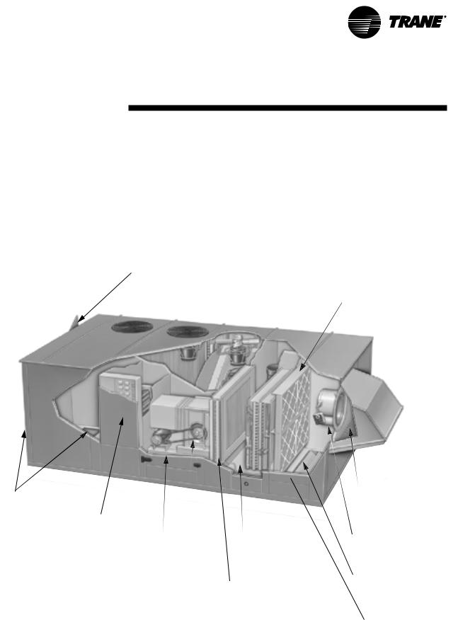
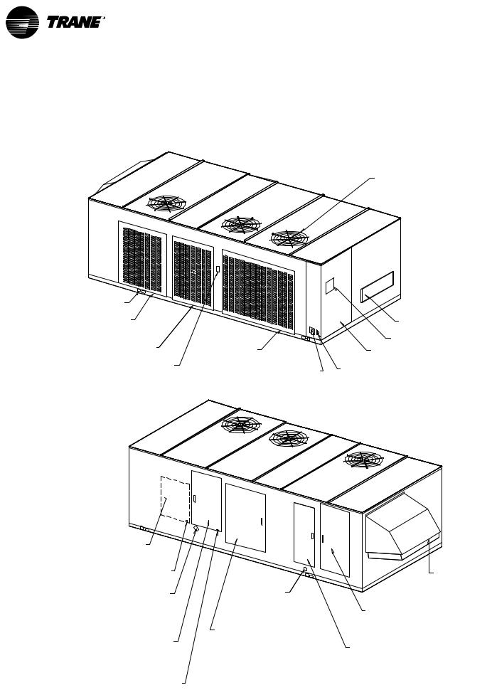
Unit mounted IntelliPak® microprocessor control with easy-to-read human interface
Horizontal or vertical discharge openings
Hi-rise electric (or gas) heat
1’’ Solid double-wall panels of foamed- in-place construction
Non-corrosive IAQ drain pan sloped in two directions
Optional condenser
Quiet FC fan reheat coil with modulating control
Figure I-GI-1. Packaged fresh air unit components
2’’ Pleated filter section with adjustable rack to 4’’
Standard protective bird screen on inlet hood
Traq® damper available for airflow measurement
Optional return air damper for unoccupied recirculation
All ship-with items are inside this compartment
FAXA-SVX01B-EN |
7 |
pre-installation Installation considerations
Pre-Installation Considerations
Checklist
The following checklist is provided to give an overview of the factoryrecommended pre-installation considerations. Follow the procedures in this section to ensure the installation is complete and adequate for proper unit operation. Verify this checklist is complete before beginning unit installation.
οVerify the unit size and tagging with the unit nameplate to ensure the correct unit is received.
οInspect the unit for possible shipping damage and make any necessary claims with the freight delivery company immediately.
οBefore installing the roof curb, remember to allow minimum recommended clearances for routine maintenance and service. Refer to unit dimensions and clearances on submittals or in Dimensions and Weights section on page 15.
οVerify the unit roof curb is installed properly prior to beginning unit installation. See the Roof Curb Installation Manual, FAXA-SVN01B-EN.
οMake proper acoustic considerations before installing unit. Do not install unit above sound-senstive locations.
οAllow adequate space for service and operating clearances. Reference page 10.
οMake provisions for correct supply power and note electrical connection knockouts locations on the unit submittals or in the Dimensions and Weights section on page 15. This includes main power and dual power connections for electric heat.
Note: Verify electric stub-out within roof curb assembly, if using bottom electrical knockouts.
οElectrical supply power must meet specific balance and voltage requirements as described in the “Electrical Requirements” section on page 36.
οUnits with gas heat, ensure adequate gas service and piping is available at unit installation location.
οEnsure the unit installation location is level.
Receiving and Handling
Shipping Package
Packaged Fresh Air units ship fully assembled.
Ship-Separate Accessories
Field-installed sensors ship separately inside the unit’s filter/return air section. Units with gas heat have temporary panels in place for shipping. The permanent panels are located in this compartment and must be field-installed. Units with the total energy wheel option have an exhaust louver that ships inside the exhaust compartment. Install the louvers after installing the unit in its final position.
 WARNING
No step surface!
Do not walk on the sheet metal drain pan. Walking on the drain pan can cause the supporting metal to collapse, causing death or serious injury.
8 |
FAXA-SVX01B-EN |

pre-installation Installation considerations
Receiving Checklist
Complete the following checklist immediately after receiving unit shipment to detect possible shipping damage. If entry into the unit is necessary, bridge between the unit’s main supports using multiple 2 x 12 boards.
οVerify that the unit nameplate data corresponds to the sales order and bill of lading (including electrical data).
οVisually inspect the unit exterior for physical signs of shipping damage or material shortages.
οIf a unit appears damaged, inspect it immediately before accepting the shipment. Remove access panels and check for interiour component damage. Make specific notations concerning the damage on the freight bill. Do not refuse delivery.
οReport concealed damage to the freight line within the allotted time after delivery. Verify with the carrier what their allotted time is to submit a claim.
Note: Failure to follow these procedures may result in no reimbursement for damages from the freight company.
οDo not move damaged material from the receiving location. It is the receiver’s responsibility to provide reasonable evidence that concealed damage did not occur after delivery.
οDo not continue unpacking the shipment if it appears damaged. Retain all packaging. Take photos of damaged material if possible.
οNotify the carrier’s terminal of the damage immediately by phone and mail. Request an immediate joint inspection of the damage by the carrier and consignee.
οNotify your Trane representative of the damage and arrange for repair. Have the carrier inspect the damage before making any repairs to the unit.
Unit Storage
Isolate all side panel service entrances and base pan openings, such as conduit holes and supply and return air openings from the ambient air until the unit is ready for startup.
If relocating the unit is necessary after the initial delivery, position the unit on the open trailer so the inlet hood is facing the rear of the trailer.
FAXA-SVX01B-EN |
9 |
pre-installation Installation considerations
Service Access
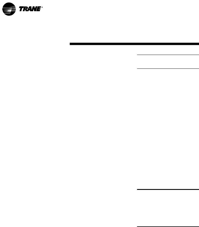
Maintain adequate clearances around and above the fresh air unit to ensure proper unit operation and allow sufficient service access. See Figure I-PC-1 for recommended clearances. If installing the unit higher than the typical curb elevation, field-construct a catwalk around it to provide safe, easy maintenance access.
 WARNING!
Hazardous voltage!
Disconnect electrical power source and remote disconnects before servicing unit. Follow proper lockout/ tagout procedures to ensure power cannot be inadvertently energized. Failure to do so may cause death or injury.
 WARNING!
Disconnect gas supply!
Before servicing unit, FIRST turn off the gas supply. Failure to turn off the gas supply can cause death or serious injury.
 WARNING!
Combustible materials!
Maintain proper clearance between the unit heat exchanger, vent surfaces, and combustible materials. Refer to this manual for proper clearances. Improper clearances can cause a fire hazard. Failure to maintain proper clearances can cause death, serious injury, or property damage.
unit without TE wheel
service access for removal of  gas or electric heaters
air path into unit
condenser airflow and compressor maintenance
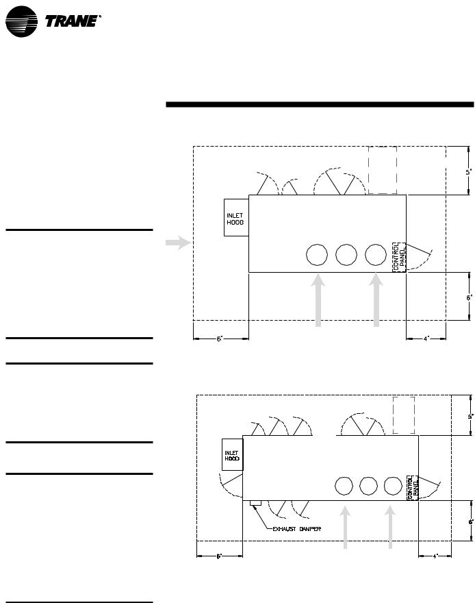
unit with TE wheel
service access for removal of
 air path into
condenser airflow
Figure I-PC-1. Top view of fresh air unit showing recommended service and code clearances.
10 |
FAXA-SVX01B-EN |
pre-installation Installation considerations
Roof Curb
You must install the roof curb before beginning unit installation. Reference the
Roof Curb Installation Manual, FAXA- SVN01B-EN for complete installation instructions. For reference, installation instructions are provided below. Reference roof curb dimensions in the Dimensions and Weights section on pages 15–32.
Note: Do not tighten any of the screws used to assemble this section until the curb has been leveled and squared in its installed location.
Roof Curb and Ductwork
Ensure the unit curb encloses the entire unit base area. It is referred to as a “full perimeter” type curb. Fabricate and install the supply air and return air ductwork adjoining the roof curb before the unit is set into place. Note electrical stub-ups within the curb.
General
Set the roof curb and Packaged Fresh Air unit level to ensure proper operation. If providing a field-fabricated roof curb, see page 12 for roof curb details for units without the total energy wheel option. See page 13 for units with the total energy wheel option. All installations must conform with local building codes, or in the absence of local codes, with the National Fuel Gas Code ANSI Z223.1.
Note: Trane has a roof curb specifically designed for the Packaged Fresh Air unit available in the following options: 14” or 24” height, and an acoustic curb. To install it, reference the Accessory Roof Curb Installation Manual, FAXA- SVN01B-EN.
Roof Support
The roof must be capable of adequately supporting the weight of the Packaged Fresh Air unit as well as the curb. See Figure I-IP-1 on page 40 for approximate unit four-corner weights.
Trane Roof Curb Installation
If the building is new, the curb may be assembled at any convenient location and installed as soon as the roof support members are in place. The curb must be mounted on the roof deck and support
provided directly below the flanges of the roof curb for further support and to minimize vibration. If the fresh air unit is to be installed on an existing building, hoist the curb shipping container to the roof, where the curb can be assembled more conveniently.
Standard Perimeter Curb Rail Assembly
Follow the procedure below as an example of how to field-assemble a field roof curb. This procedure also applies to the Trane standard 14” roof curb. Reference pages 12 & 13 for assembly drawings.
1.Attach corner angle (7) using 4 sheet metal screws to the end of end rail (1) adjacent to side rail (3). Place the clearance holes in the corner angle toward the top of the curb.
2.Attach end rail (1) to side rail (3) using 4 sheet metal screws.
3.Align side rail (4) next to side rail (3) and attach crossmember (11) perpendicular to both side rails at the joint using eight sheet metal screws.
4.Attach corner angle (8) using eight sheet metal screws to end rail (2) and side rail (4). Place the clearance holes in the corner angle toward the top of the curb.
5.Attach corner angle (9) using eight sheet metal screws to end rail (2) and side rail (5). Place the clearance holes in the corner angle toward the top of the curb.
6.Align side rail (6) next to side rail (5) and attach crossmember (11) perpendicular to both side rails at the joint using eight sheet metal screws.
7.Attach corner angle (10) using eight sheet metal screws to end rail (1) and side rail (6). Place the clearance holes in the corner angle toward the top of the curb.
Return and Exhaust Air Opening
Assembly
8.Place end rail (12) between side rail (3) and side rail (6) with flanges positioned away from the return air opening and attach it with two sheet metal screws at each end. Use rails (14), (15), (16), and (17) as spacers.
9.Place side rail (14) between end rail (1) and end rail (12) with flanges positioned away from the return air opening and attach it with two sheet metal screws at each end.
10.Place side rail (15) between end rail
(1)and end rail (12) with flanges positioned toward the return air opening and attach it with two sheet metal screws at each end.
11.Place side rail (16) between end rail
(1)and end rail (12) with flanges positioned away from side rail (15) and attach it with two sheet metal screws at each end.
12.Place side rail (17) between end rail
(1)and end rail (12) with flanges positioned away from the exhaust air opening and attach it with two sheet metal screws at each end.
Supply Air Opening Assembly
13.Place end rail (13) between side rail
(4)and side rail (5) with flanges positioned away from the supply air opening and attach it with two sheet metal screws at each end. Use rails (18) and (19) as spacers.
14.Place side rail (18) between end rail
(2)and end rail (13) with flanges positioned away from the supply air opening and attach it with two sheet metal screws at each end.
15.Place side rail (19) between end rail
(2)and end rail (13) with flanges positioned away from the supply air opening and attach it with two sheet metal screws at each end.
Units with the Total Energy Wheel Only
16.Attach corner angle (26) using five sheet metal scres to the side of duct support (25) without flanges. Place the clearance holes in the corner angle toward the top of the curb.
17.Align side rail (23) next to side rail (3) and attach crossmember assembly (25) and (26) perpendicular to both side rails at the joint using ten sheet metal screws.
FAXA-SVX01B-EN |
11 |
pre-installation Installation considerations
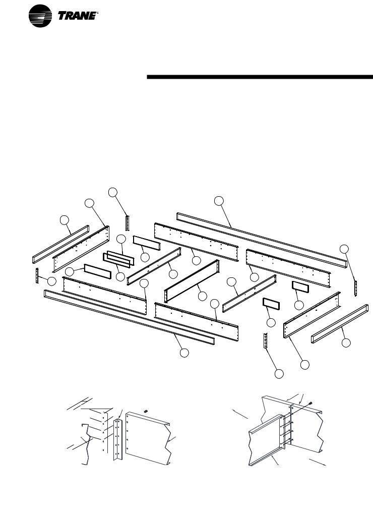
Standard roof curb assembly, units without TE wheel option
7
1
23
15
R/A
14
E/A
17
16
10 |
6 |
|
Note: Center lines connect corresponding holes in the rails and crossmember. All screws are installed from outside the curb.
corner angle 

end rail
Typical std. curb corner assembly for units without the total energy wheel option
Curb legend |
|
|
(1) end rail (R/A end) |
(13) duct support end rail |
|
(2) end rail (S/A end) |
(14) duct support end rail (R/A end) |
|
(3) side rail |
(15) duct support side rail (R/A end) |
|
(4) side rail |
(16) duct support side rail (E/A end) |
|
(5) side rail |
(17) duct support side rail (E/A end) |
|
(6) side rail |
(18) duct support side rail (S/A end) |
|
(7) corner angle |
(19) duct support side rail (S/A end) |
|
(8) corner angle |
(20) |
6” wood nailer; side |
(9) corner angle |
(21) |
6” wood nailer; side |
(10) corner angle |
(22) |
6” wood nailer; end |
(11) crossmember |
(23) 6” wood nailer; end |
|
(12) duct support end rail |
|
|
20 |
|
|
8
|
3 |
|
|
12 |
|
|
4 |
|
|
|
|
|
|
|
13 |
|
11 |
|
S/A |
|
|
|
|
|
|
5 |
18 |
|
|
|
|
|
|
|
19 |
22
21
2
9
side rails
side rail |
return air end |
|
supply air end supply air end
crossmember
Note: Center lines connect corresponding holes in the rails and crossmember. All screws are installed from outside the curb.
Typical std. curb rail and crossmember assembly for units without the total energy wheel option
12 |
FAXA-SVX01B-EN |
pre-installation Installation considerations
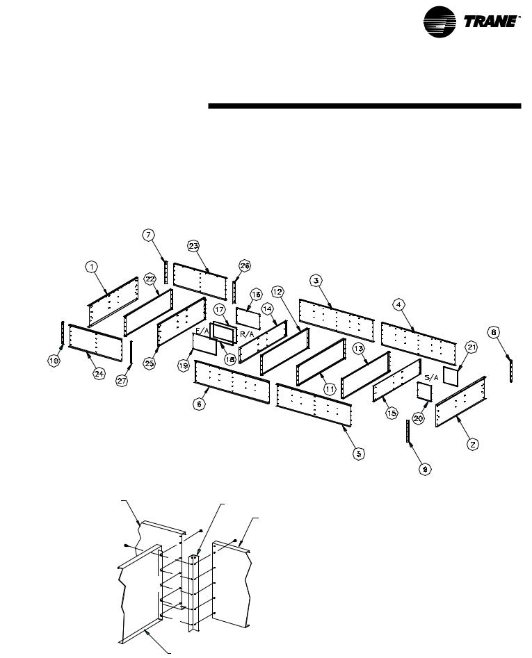
Standard roof curb assembly, units with the TE wheel
Curb legend |
|
|
|
(1) end rail (R/A, E/A end) |
(15) |
duct support end rail |
|
(2) end rail (S/A end) |
(16) |
duct support side rail (R/A end) |
|
(3) side rail |
(17) |
duct support side rail (R/A end) |
|
(4) side rail |
(18) |
duct support side rail (E/A end) |
|
(5) side rail |
(19) |
duct support side rail (E/A end) |
|
(6) side rail |
(20) |
duct support side rail (S/A end) |
|
(7) corner angle |
(21) |
duct support side rail (S/A end) |
|
(8) corner angle |
(22) |
crossmember |
|
(9) corner angle |
(23) side rail |
||
(10) |
corner angle |
(24) side rail |
|
(11) |
crossmember |
(25) duct support end rail |
|
(12) |
crossmember |
(26) |
corner angle |
(13) |
crossmember |
(27) |
corner angle |
(14) |
duct support end rail |
|
|
GEND
side rail
corner angle
side rail
duct support end rail
Typical standard roof curb assembly for units with the TE wheel
FAXA-SVX01B-EN |
13 |
pre-installation Installation considerations
Acoustic Considerations
Before determining the final unit installation site, remember that proper unit placement is critical in reducing transmitting sound levels to the building. The ideal time to make provisions to reduce sound transmissions is during the design phase. The most economical means of avoiding a potential acoustical problem is to place units in areas that are not acoustically sensitive. Ideal locations are over over corridors, utility rooms, toilets, or other areas where higher sounds levels below the unit may be acceptable.
Follow these basic guidelines to help minimize sound transmission through the building structure:
•Locate the unit’s center of gravity close to or over a column or main support beam.
•If the roof structure is very light, replace roof joists using a structural shape in the critical areas described above.
Note: Cut applicable holes only for the supply, exhaust, and return duct penetration in the roof deck. To maintain roof integrity and prevent possible property damage, do not remove the roof decking from the inside perimeter of the curb.
Installation Preparation
Before installing the unit, perform the following procedures to ensure proper unit operation.
1.Verify the roof curb is level. To ensure proper unit operation, install the unit level (zero tolerance) in both horizontal axes. Failure to level the unit properly can result in condensate management problems, such as standing water inside the unit. Standing water and wet surfaces inside units can result in microbial growth (mold) in the drain pan that may cause unpleasant odors and serious health-related indoor air quality problem.
2.Allow adequate service and code clearances as recommended in “Service Access” section on page 10.
3.Position the unit and skid assembly in its final location. Test lift the unit to determine exact unit balance and stability before hoisting it to the installation location. See Figure I-IP-2 on page 41 for typical rigging procedures, including cautions and proper uses of such equipment as fork lifts, spreader bars, and hooks.
14 |
FAXA-SVX01B-EN |
Installation |
dimensions |
& weights |
|
|
|
|
|
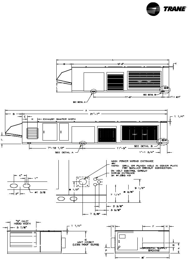
Typical exterior dimensions, ft./in.
outdoor side view, unit without total energy wheel
outdoor side view, unit with total energy wheel
detail B
lifting hole detail A
CONTROL PANEL
END VIEW
inlet hood end view
control panel end view
unit size |
A |
B |
C |
D |
E |
F |
G |
H |
J |
K |
L |
M |
N |
P |
|
without TE wheel |
|
|
|
|
|
|
|
|
|
|
|
|
|
|
|
031, 041 |
18' - 10" |
2' - 7" 4' - 2" |
3' - 10" |
— |
3' - 2" |
10" |
9" |
1' - 11 1/2" |
1 1/4" |
1' - 6 1’4" |
ø 2 |
1/2" |
— |
— |
|
051, 066 |
19' - 3" |
3' |
5' - 10" |
4' - 1" |
— |
3' - 6" |
1' - 3" |
10 1’4" |
2' - 4 1/2" |
1 1/4" |
3' - 6 3/4" |
ø 3" |
|
|
|
withTEwheel |
|
|
|
|
|
|
|
|
|
|
|
|
|
|
|
031, 041 |
24' - 2" |
2' - 7" 4' - 2" |
3' - 10" |
9 1/4" |
3' - 2" |
10" |
9" |
1' - 11 1/2" |
1' 6" |
1' - 6 1’4" |
ø 2 1/2" |
7" |
1' - 3/4" |
||
051, 066 |
24' - 7" |
3' |
5' - 10" |
4' - 1" |
8" |
3' - 6" |
1' - 3" |
10 - 1’4" |
2' - 4 1/2" |
1' 8" |
3' - 6 3/4" |
ø 3" |
7" |
11" |
|
FAXA-SVX01B-EN |
15 |
|
dimensions |
Installation |
& weights |
|
|
|
|
unit without TE wheel - indoor side view (electric heat version shown)
unit with TE wheel - indoor side view (electric heat version shown)
single & dual gas heater options
16 |
FAXA-SVX01B-EN |
Installation |
dimensions |
& weights |
|
|
|
|
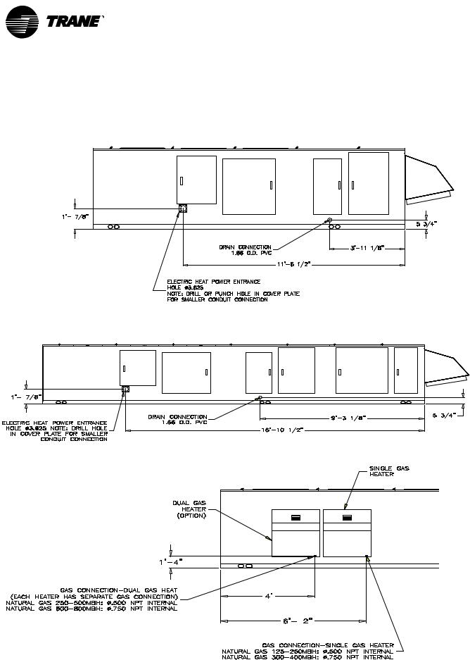
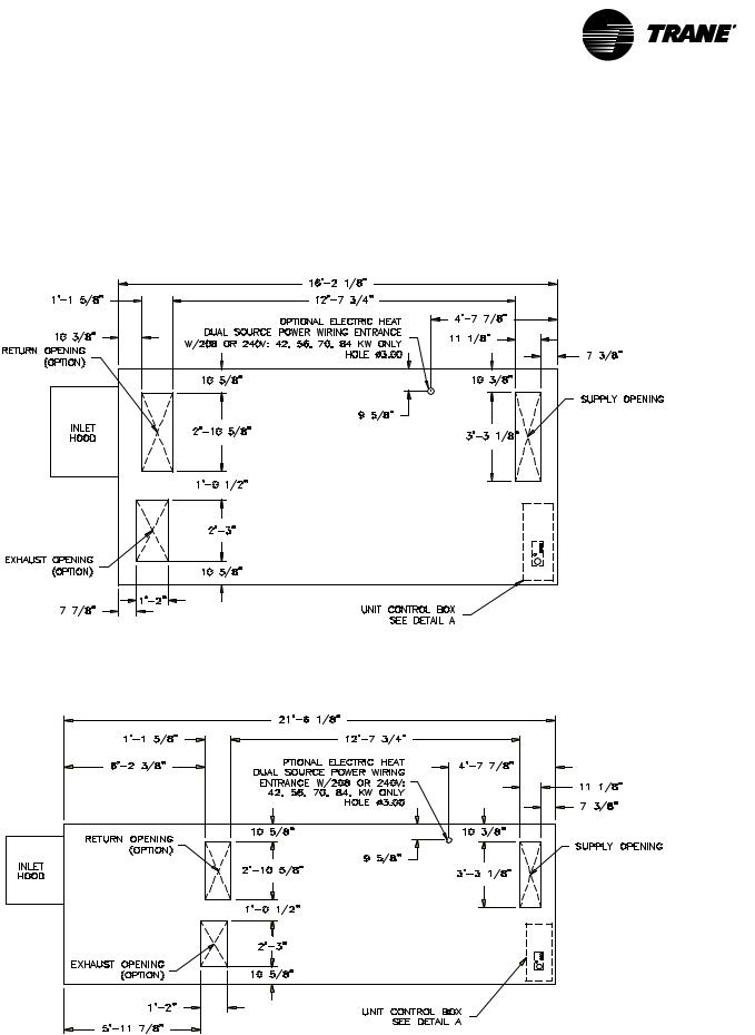
|
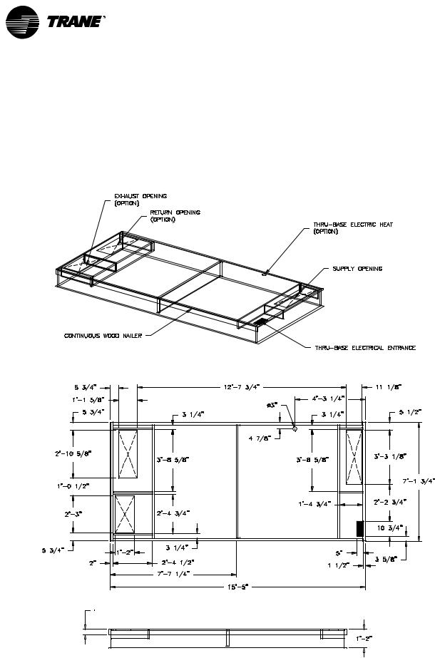
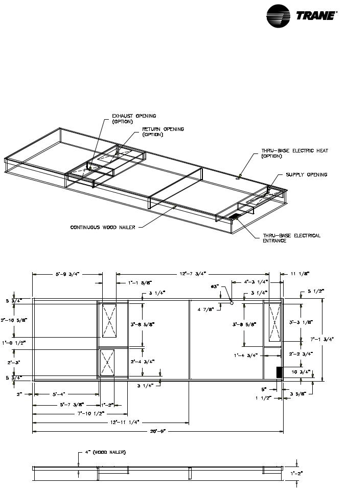
Unit base plan view, duct openings & thru-base power openings, unit sizes 031 & 040
unit without TE wheel
unit with TE wheel
FAXA-SVX01B-EN |
17 |
|
dimensions |
Installation |
& weights |
|
|
|
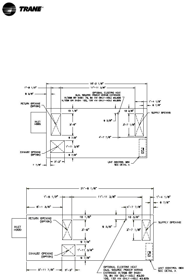
|
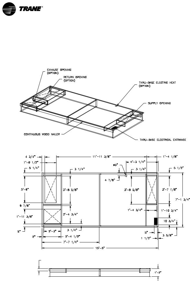
Unit base plan view, duct openings & thru-base power openings, unit sizes 051 & 066
unit without TE wheel
unit with TE wheel
18 |
FAXA-SVX01B-EN |
Installation |
dimensions |
& weights |
|
|
|
|
|
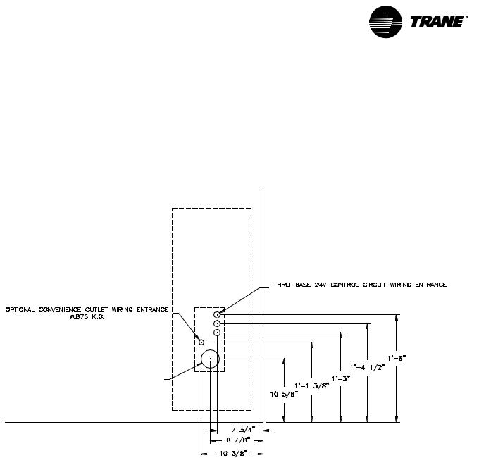
Fresh air unit control panel detail, all unit sizes
detail A
3x 
THRU-BASE MAIN POWER WIRING ENTRANCE |
HOLE Ø3.000’’ |
NOTE: DRILL OR PUNCH HOLE IN COVER PLATE FOR |
SMALLER CONDUIT CONNECTION |
top view
FAXA-SVX01B-EN |
19 |

|
dimensions |
Installation |
& weights |
|
|
|
|
Exterior features for unit sizes 031 & 040, without TE wheel
CONDENSER FANS
CONVENIENCE OUTLET (OPTION) |
|
|
|
LIFTING HOLES |
|
|
|
|
|
|
HORIZONTAL DISCHARGE |
MAIN COMPRESSOR ACCESS PANEL |
|
|
(OPTION) |
(40x35) |
MAIN CONDENSER |
HUMAN INTERFACE |
|
|
|||
REHEAT COMPRESSOR/COIL ACCESS PANEL |
COIL ACCESS |
ACCESS DOOR |
|
(34x36) |
PANEL |
(68x36) |
|
|
|
|
UNIT CONTROL PANEL |
|
|
MAIN POWER WIRING ENTRANCE |
|
|
|
(CAN ALSO BE RUN THRU- |
24 VOLT CONTROL CIRCUIT WIRING ENTRANCE |
|
|
BASE) |
|
|
|
(CAN ALSO BE RUN THRU-BASE) |
|
|
|
|
|
DUAL GAS HEAT ACCESS PANEL (EACH HEATER HAS SEPARATE PANEL)
(16x23)
INLET HOOD
GAS CONNECTION–DUAL GAS HEAT (EACH HEATER HAS SEPARATE GAS CONNECTIONS)
NATURAL GAS 250–400 MBH: Æ.500 NPT INTERNAL
|
|
CONDENSATE |
FILTER AND DAMPER ACCESS DOOR |
|
|
DRAIN CONNECTION |
|
|
|
(25x39) |
|
|
ELECTRIC HEAT POWER WIRING ENTRANCE |
|
|
|
|
|
|
|
(ALSO CAN BE RUN THRU-BASE) |
|
EVAP COIL AND |
|
ELECTRIC HEATER ELECTRICAL PANEL (24x30) |
|
|
|
|
CONDENSATE DRAIN PAN |
|
|
-OR- |
|
ACCESS DOOR (18x34) |
|
GAS HEAT PANEL (16x23) |
|
|
|
-OR- |
|
|
|
FIXED PANEL FOR NO-HEAT OPTION |
|
|
|
OR HYDRONIC HEAT INTERFACE OPTION (24x47) |
|
|
|
SUPPLY FAN ACCESS DOOR |
|
|
20 |
(33X34) |
|
FAXA-SVX01B-EN |
|
|
Installation |
dimensions |
& weights |
|
|
|
|
|
Exterior features, unit sizes 031 & 040 with TE wheel
FAXA-SVX01B-EN |
21 |
|
dimensions |
Installation |
& weights |
|
|
|
|
Exterior features for unit sizes 051 & 066, without TE wheel
CONDENSER FANS
LIFTING HOLES |
REHEAT COMPRESSOR/
COIL ACCESS PANEL (40x52)
MAIN COMPRESSOR/ |
MAIN COMPRESSOR/ |
COIL ACCESS PANEL (34x52) |
COIL ACCESS PANEL |
|
(68x52) |
CONVENIENCE OUTLET
(OPTION) MAIN POWER WIRING ENTRANCE (CAN ALSO BE RUN THRU-BASE)
HORIZONTAL DISCHARGE (OPTION)
HUMAN INTERFACE
ACCESS DOOR
UNIT CONTROL PANEL
24 VOLT CONTROL CIRCUIT WIRING ENTRANCE (CAN ALSO BE RUN THRU-BASE)
DUAL GAS HEAT ACCESS PANEL (EACH HEATER HAS SEPARATE PANEL)
(16x23)
GAS CONNECTION–DUAL GAS HEAT (EACH HEATER HAS SEPARATE GAS CONNECTIONS)
ELECTRIC HEAT POWER WIRING ENTRANCE FOR 208/230 V: 70, 84, 100, 122 kW (CAN ALSO BE RUN THRU-BASE)
ELECTRIC HEATER ELECTRICAL PANEL (24x49)
-OR-
SINGLE GAS HEAT ACCESS PANEL (16x23)
-OR-
FIXED PANEL FOR NO-HEAT OPTION
OR HYDRONIC HEAT INTERFACE OPTION (24x67)
GAS CONNECTION–SINGLE GAS HEATER
INLET HOOD
CONDENSATE DRAIN
CONNECTION
FILTER AND DAMPER ACCESS DOOR (25x59)
SUPPLY FAN ACCESS DOOR (33x54)
EVAP COIL & CONDENSATE DRAIN PAN ACCESS DOOR
(18x54)
22 |
FAXA-SVX01B-EN |

Installation |
dimensions |
& weights |
|
|
|
|
|
Exterior features for unit sizes 051 & 066 with TE wheel
FAXA-SVX01B-EN |
23 |
|
dimensions |
Installation |
& weights |
|
|
|
|
Standard curb, unit sizes 031 & 040 without TE wheel
6’’ WOOD NAILER
24 |
FAXA-SVX01B-EN |
Installation |
dimensions |
& weights |
|
|
|
|
|
Standard roof curb, unit sizes 031 & 040 with TE wheel
6" WOOD NAILER
FAXA-SVX01B-EN |
25 |
|
dimensions |
Installation |
& weights |
|
|
|
|
Standard curb , unit sizes 051 & 66 without TE wheel
6’’ WOOD NAILER
26 |
FAXA-SVX01B-EN |
Loading...