


 Loading...
Installation, Operation,
and Maintenance
Tracer™ TD-5 Display
for ReliaTel™ Controller
 SAFETY WARNING
Only qualified personnel should install and service the equipment. The installation, starting up, and servicing of heating, ventilating, and airconditioning equipment can be hazardous and requires specific knowledge and training. Improperly installed, adjusted or altered equipment by an unqualified person could result in death or serious injury. When working on the equipment, observe all precautions in the literature and on the tags, stickers, and labels that are attached to the equipment.
November 2013 |
RT-SVX49A-EN |

Warnings, Cautions and Notices
Warnings, Cautions and Notices. Note that warnings, cautions and notices appear at appropriate intervals throughout this manual. Warnings are provided to alert installing contractors to potential hazards that could result in death or personal injury. Cautions are designed to alert personnel to hazardous situations that could result in personal injury, while notices indicate a situation that could result in equipment or property-damage-only accidents.
Your personal safety and the proper operation of this machine depend upon the strict observance of these precautions.
Read this manual thoroughly before operating or servicing this unit.
ATTENTION: Warnings, Cautions, and Notices appear at appropriate sections throughout this literature. Read these carefully:
 WARNING
 CAUTIONs
NOTICE:
Indicates a potentially hazardous situation which, if not avoided, could result in death or serious injury.
Indicates a potentially hazardous situation which, if not avoided, could result in minor or moderate injury. It could also be used to alert against unsafe practices.
Indicates a situation that could result in equipment or property-damage only accidents.
Important
Environmental Concerns!
Scientific research has shown that certain man-made chemicals can affect the earth’s naturally occurring stratospheric ozone layer when released to the atmosphere. In particular, several of the identified chemicals that may affect the ozone layer are refrigerants that contain Chlorine, Fluorine and Carbon (CFCs) and those containing Hydrogen, Chlorine, Fluorine and Carbon (HCFCs). Not all refrigerants containing these compounds have the same potential impact to the environment.Trane advocates the responsible handling of all refrigerants-including industry replacements for CFCs such as HCFCs and HFCs.
municipalities may have additional requirements that must also be adhered to for responsible management of refrigerants. Know the applicable laws and follow them.
 WARNING
Proper Field Wiring and Grounding
Required!
All field wiring MUST be performed by qualified personnel. Improperly installed and grounded field wiring poses FIRE and ELECTROCUTION hazards. To avoid these hazards, you MUST follow requirements for field wiring installation and grounding as described in NEC and your local/state electrical codes. Failure to follow code could result in death or serious injury.
 WARNING
Personal Protective Equipment (PPE)
Required!
Installing/servicing this unit could result in exposure to electrical, mechanical and chemical hazards.
•Before installing/servicing this unit, technicians MUST put on all Personal Protective Equipment (PPE) recommended for the work being undertaken. ALWAYS refer to appropriate MSDS sheets and OSHA guidelines for proper PPE.
•When working with or around hazardous chemicals, ALWAYS refer to the appropriate MSDS sheets and OSHA guidelines for information on allowable personal exposure levels, proper respiratory protection and handling recommendations.
•If there is a risk of arc or flash, technicians MUST put on all Personal Protective Equipment (PPE) in accordance with NFPA 70E or other country-specific requirements for arc flash protection, PRIOR to servicing the unit.
Failure to follow recommendations could result in death or serious injury.
Responsible Refrigerant Practices!
Trane believes that responsible refrigerant practices are important to the environment, our customers, and the air conditioning industry. All technicians who handle refrigerants must be certified.The Federal Clean Air Act (Section 608) sets forth the requirements for handling, reclaiming, recovering and recycling of certain refrigerants and the equipment that is used in these service procedures. In addition, some states or
© 2013Trane All rights reserved |
RT-SVX49A-EN |
Table of Contents |
|
Warnings, Cautions and Notices . . . . . . . . . . |
2 |
Introduction . . . . . . . . . . . . . . . . . . . . . . . . . . . . . |
4 |
Hardware . . . . . . . . . . . . . . . . . . . . . . . . . . . . . |
4 |
Power . . . . . . . . . . . . . . . . . . . . . . . . . . . . . |
4 |
Communication . . . . . . . . . . . . . . . . . . . . . |
4 |
Screen characteristics . . . . . . . . . . . . . . . . |
4 |
Touchscreen Guidelines . . . . . . . . . . . . . . . . |
4 |
Dimensions . . . . . . . . . . . . . . . . . . . . . . . . . . . |
5 |
Specifications and Agency Compliance . . . |
6 |
Supported Languages . . . . . . . . . . . . . . . . . . |
6 |
Screen Overview . . . . . . . . . . . . . . . . . . . . . . |
7 |
Top Display Area . . . . . . . . . . . . . . . . . . . . |
7 |
Main Display Area . . . . . . . . . . . . . . . . . . . |
7 |
Bottom Display Area . . . . . . . . . . . . . . . . . |
7 |
Installing the Tracer™ TD-5 Display . . . . . . . |
8 |
Packaged Contents . . . . . . . . . . . . . . . . . . . . |
8 |
Additional Mounting Parts . . . . . . . . . . . . . |
8 |
Installing the TD-5 Display onto a VESA Mounting Bracket . . . . . . . . . . . . . . . . . . . . . . 8
Powering up the TD-5 Display for the First Time . . . . . . . . . . . . . . . . . . . . . . . . . . . . . . . . . 9
Alarms . . . . . . . . . . . . . . . . . . . . . . . . . . . . . . . . . 10
Active Alarms . . . . . . . . . . . . . . . . . . . . . . . . 10
Historic Alarms . . . . . . . . . . . . . . . . . . . . . . . 11
Viewing Active and Historic Alarms . . . . . 11
Alarm Icons . . . . . . . . . . . . . . . . . . . . . . . . . . 12
Sorting Alarms . . . . . . . . . . . . . . . . . . . . . . . 12
Reports . . . . . . . . . . . . . . . . . . . . . . . . . . . . . . . . 13
Custom Reports . . . . . . . . . . . . . . . . . . . . . . 13 Creating a Custom Report . . . . . . . . . . . . 13 Editing a Custom Report . . . . . . . . . . . . . 15
About . . . . . . . . . . . . . . . . . . . . . . . . . . . . . . . 16
System Report . . . . . . . . . . . . . . . . . . . . . . . 17
Economizer/Ventilation Report . . . . . . . . . 18
Compressor Report . . . . . . . . . . . . . . . . . . . 18
Heating Report . . . . . . . . . . . . . . . . . . . . . . . 19
Configuration Report . . . . . . . . . . . . . . . . . . 19
Sensor Report . . . . . . . . . . . . . . . . . . . . . . . . 20
Binary Input Report . . . . . . . . . . . . . . . . . . . 20
Binary Output Report . . . . . . . . . . . . . . . . . . 21
Graphs . . . . . . . . . . . . . . . . . . . . . . . . . . . . . . . . . 22
Creating a Custom Graph . . . . . . . . . . . . . . 22
Standard Graphs . . . . . . . . . . . . . . . . . . . . . . 25
Space Temperature: . . . . . . . . . . . . . . . . . 25
Compressor Graph: . . . . . . . . . . . . . . . . . . 25
VAV System: . . . . . . . . . . . . . . . . . . . . . . . 26
Economizer Graph: . . . . . . . . . . . . . . . . . . 26
Outside Air Ventilation: . . . . . . . . . . . . . . 26
CO2 Graph: . . . . . . . . . . . . . . . . . . . . . . . . . 26
Humidity Graph: . . . . . . . . . . . . . . . . . . . . 26
Heat Pump Graph: . . . . . . . . . . . . . . . . . . . 26
Settings . . . . . . . . . . . . . . . . . . . . . . . . . . . . . . . . 27
Setpoints . . . . . . . . . . . . . . . . . . . . . . . . . . . . 27
Setup . . . . . . . . . . . . . . . . . . . . . . . . . . . . . . . . 28
Display Settings Screen . . . . . . . . . . . . . . . . 29
Display Preferences . . . . . . . . . . . . . . . . . 29
Language . . . . . . . . . . . . . . . . . . . . . . . . . . 31
Date and Time . . . . . . . . . . . . . . . . . . . . . . 31
Clean Touchscreen . . . . . . . . . . . . . . . . . . 32
Troubleshooting . . . . . . . . . . . . . . . . . . . . . . . . 33
Identifying and Diagnosing Issues . . . . . . . 33
RT-SVX49A-EN |
3 |
Introduction
The purpose of this guide is to assist you in installing, programming, and operating theTracer™TD-5 display, which operates with the ReliaTel™ Controller.This guide describes how to access the screens and the types of information that appear on the screens.
TheTracer™TD-5 display allows you to view data and make operational changes on the following types of applications:
•Voyager™
•Precedent™
Hardware
TheTracer™TD-5 is a durable touch screen display that is designed to operate in both indoor or outdoor environments.TheTD-5 display utilizes a standard 75mm VESA mounting pattern for installation. Alternatively, it can be installed with a user-supplied VESA mount.
Power
TheTracer™TD-5 display is powered by 24 VAC or 24 VDC and requires 21 VA power, which it receives through a power cable.The display is typically connected to J10 of the RTRM Module, but it can also be powered from an alternate power source.
Communication
Communication is provided to theTD-5 through the RTRM J10 connector.
Screen characteristics
The 5-inch WVGA 800 x 480 resolution touch-sensitive color screen is LED backlit, which enables viewing in poor light conditions including outdoor usage (with the exception of direct sunlight).
Touchscreen Guidelines
The touch screen registers the downward pressure of a touch. Light, quick, yet deliberate touches are most effective.Touching with more pressure has no effect.
Recommended tools to use:
•finger
•thumb
•pencil eraser
Do not use:
•a screwdriver
•a pen
•a pencil point
•any other sharp or pointed object that might scratch the screen surface
4 |
RT-SVX49A-EN |
Introduction
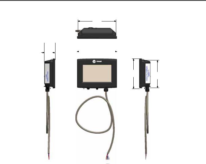
Dimensions
147,0 [5.8]
 42,1
42,1  [1.7]
[1.7]
32,0 |
|
|
|
|
154,0 |
|
|
|
[1.3] |
|
[6.1] |
|
|
|
|||
|
|
|
|
|
|
|
|
|
|
|
|
|
|
|
|
|
|
|
|
|
|
|
|
|
|
|
|
|
|
|
|
|
|
|
|
115,3 [4.5]
106,4 [4.2]
Note: The power cable is permanently attached to the TD-5 display. The power connector
provides strain relief and protection from the
RT-SVX49A-EN |
5 |
Introduction
Specifications and Agency
Compliance
Specification
Input power: |
24 Vac ± 15%, or 24 Vdc ± 10% 21 VA, 50 or |
|
60 Hz |
||
|
||
|
|
|
Storage |
–67°F to 203°F (–55°C to 95°C) |
|
Humidity: Between 5% to 100% (non- |
||
temperature: |
||
condensing) |
||
|
||
|
|
|
Operating |
Temperature: –40°F to 158°F (–40°C to 70°C) |
|
Humidity: Between 5% to 100% (non- |
||
temperature: |
||
condensing) |
||
|
||
|
|
|
|
Mounting surface must support 0.93 lb (422 |
|
Mounting weight: |
grams) |
|
|
Mounting Type: VESA (75 mm x 75 mm) |
|
|
|
|
Environmental |
IP55 (dust and strong water protected) |
|
rating |
||
(PN: X19070632020) |
||
(enclosure): |
||
|
||
|
|
Agency Compliance
•UL916 PAZX, Open Energy Management Equipment
•UL94-5V, Flammability
•FCC CFR Title 47, Part 15.109: Class A Limit, (30 MHz – 4 GHz)
•CE EMC Directive 2004/108/EC
•CE EMC Directive 2004/108/EC
Supported Languages
TheTD-5 display supports 26 built-in languages. For help on how to select a specific language for the display, see “Language,” p. 31.
Arabic |
Hungarian |
Romanian |
Chinese (Simplified) |
Indonesian |
Russian |
Chinese (Traditional) |
Italian |
Spanish (Mexico) |
Czech |
Japanese |
Spanish (Spain) |
Dutch |
Korean |
Swedish |
English |
Norwegian |
Thai |
French |
Polish |
Indonesian |
German |
Portuguese (Brazil) |
French Canadian |
Hebrew |
Portuguese (Portugal) |
|
6 |
RT-SVX49A-EN |

Introduction
Screen Overview
There are three distinct areas on theTD-5 screens:
•Top display area
Figure 1. Tracer™ TD-5 display screen
Top display area
Main display area
Bottom display  area
area 
Top Display Area
The Back button, when touched, returns to the previous screen visited.
The Home button, when touched, navigates to the Home Page. Home can be configured. See “Display Preferences,” p. 29.
The Header Data Point is a user-defined data point that will appear at the top portion of each display screen. This value can be the present value of any point in the TD-5. See “Header Data Point,” p. 29.
Main Display Area
This area serves as the main task area in which you can view custom graphics, create reports, view and take action on alarms, and view or change display settings.
•Main display area
•Bottom display area
Bottom Display Area
The bottom display area contains functional buttons that provide a link to the appropriate screen.
Screen brightness settings: Touch this icon to change the display’s brightness.
Touch this button to open the Alarms screen. When an alarm is present, this button will flash red.
Touch this button to navigate to the
Reports screen.
Touch this button to open the Data Graphs screen to view Graphs.
Touch this button to open the Settings screen, which contains options for controls, security (if enabled), and display settings.
Language selection: Touch this icon to select a language that will be displayed on all screens.
RT-SVX49A-EN |
7 |

Installing the Tracer™ TD-5 Display
This section describes installation procedures when mounting theTracer™TD-5 display near the RTRM module or remotely mounted up to 328 ft (100 m) by using a field-suppled 75 mm VESA mounting bracket. Read and observe all warning and caution statements before you begin the installation procedure.
4.Securely tighten the M-4 screws using a Phillips screwdriver.
 WARNING
Hazardous Voltage!
Disconnect all electric power, including remote disconnects before servicing. Follow proper lockout/ tagout procedures to ensure the power can not be inadvertently energized. Failure to disconnect power before servicing could result in death or serious injury.
Packaged Contents
•One (1)Tracer™TD-5 display with permanently attached 2.6 ft (0.8 m) power cable with male connector
•Four (4) M-4 screws
•Four (4) spacer washers
Additional Mounting Parts
•TD-5 Display Low Profile Mounting Bracket (VESA 75mm) (PN: X05010511010)
Installing the TD-5 Display onto a VESA Mounting Bracket
TheTracer™TD-5 can be mounted near the RTRM module in the control panel, or remotely mounted up to 328 ft (100 m) by using a field-suppled 75 mm VESA mount.
Remote mounting requires the following additional fieldsupplied components:
•A power source that will supply 24 VAC to the display
•Power cables
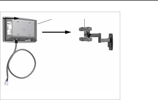
Many commercial 75mm VESA mounting brackets are available, which range from a simple wall mount to tilt- and-swivel mounts such as the one shown in Figure 2, p. 9, or theTD-5 Display Low Profile Mounting Bracket (VESA 75mm) (PN: X05010511010).
To install onto a VESA mounting bracket:
1.Disconnect power at the circuit breaker and perform lockout/tagout procedures.
2.Mount the VESA mounting bracket according to manufacturer’s instructions.
3.Position theTD-5 display 1onto the VESA mounting bracket 2and align the four mounting holes with the bracket while inserting and hand-tightening the four M-4 screws. (Some brands ofVESA mounting brackets may require the use of the four spacer washers to allow the M-4 screws to tighten properly.)
8 |
RT-SVX49A-EN |
Installing the Tracer™ TD-5 Display
Figure 2. Example VESA mounting
2
1
Powering up the TD-5 Display for the First Time
After completing the installation instructions in “Installing theTracer™TD-5 Display,” p. 8,TheTD-5 display can be powered up.
Before applying power to theTD-5 Display, verify that the
RTRM Module is powered up.
Upon successful power up, theTD-5 Display will default to the configured home screen.The System Report is the factory default.
Important: Do not attempt to update the TD-5 Display from a connection type other than a USB.
RT-SVX49A-EN |
9 |
Alarms
Alarms appear on theTracer™TD-5 display immediately upon detection.Touch the Alarms button in the bottom display area to view the Alarms screen.
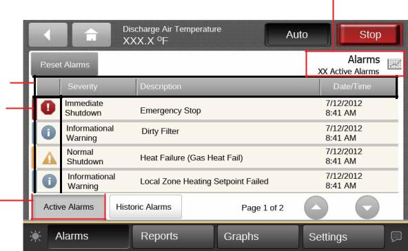
Active Alarms
Figure 3, p. 10 shows the Active Alarms screen and commonly used functions. Configuration is not required in order for points in alarm to appear in the Active Alarms
Figure 3. Active alarms screen
Sortable columns
Alarm severity
Active Alarms  button
screen. When the alarm clears and the point returns to normal, the alarm will automatically be removed from the list.The number of active alarms is displayed in the top right portion of the screen. When an active alarm is present, the alarm button at the bottom of the screen will flash.
The Alarms screen defaults to Active Alarms.The Active Alarms button has a shaded appearance which indicates that you are viewing active alarms.
Number of active alarms
10 |
RT-SVX49A-EN |
Alarms
Historic Alarms
On the Alarms screen, touch the Historic Alarms button to view all alarms, commonly referred to as the event log (see Figure 4, p. 11).
Figure 4. Historic alarms screen
Sortable columns
Alarm severity
Number of historic alarms
Historic Alarms button
Viewing Active and Historic
Alarms
•Active alarms:These are alarms that require attention. All alarms that are currently active appear when you view this category. Active alarms are not reset by way of the display. Active alarms will clear automatically when the condition causing the alarm is removed.
•Historic alarms: Historic alarms appear when you view this category.The alarms are listed in chronological order.
Alarm Severity
A color-code icon representing the severity of each alarm is shown under the severity (!) column. For a description of the five alarm icons, see Table 1, p. 12.
Sortable Alarms
You can sort active alarms by touching one of the column headers. Choose to sort by severity (!), date and time, point name, or description.
RT-SVX49A-EN |
11 |
Loading...