


Air Conditioning
Clinic
Refrigeration
Compressors
One of the Fundamental Series
TRG-TRC004-EN

BUSINESS REPLY MAIL
FIRST-CLASS MAIL |
PERMIT NO. 11 |
LA CROSSE, WI |
POSTAGE WILL BE PAID BY
THE TRANE COMPANY
Attn: Applications Engineering
3600 Pammel Creek Road
La Crosse WI 54601-9985
BUSINESS REPLY MAIL
FIRST-CLASS MAIL |
PERMIT NO. 11 |
LA CROSSE, WI |
POSTAGE WILL BE PAID BY
THE TRANE COMPANY
Attn: Applications Engineering
3600 Pammel Creek Road
La Crosse WI 54601-9985
NO POSTAGE NECESSARY IF MAILED IN THE
UNITED STATES
NO POSTAGE NECESSARY IF MAILED IN THE
UNITED STATES
Crop to width of 7.75”

edge from 75”.0 Perforation
bottom/top from 5”.5 Perforation
Comment Card
We want to ensure that our educational materials meet your ever-changing resource development needs. Please take a moment to comment on the effectiveness of this Air Conditioning Clinic.
Refrigeration Compressors
One of the Fundamental Series
TRG-TRC004-EN
About me …
Level of detail (circle one) |
Too basic |
|
|
Just right |
|
|
Too difficult |
|||
Rate this clinic from 1–Needs Improvement to 10–Excellent … |
|
|
|
|
||||||
Content |
1 |
2 |
3 |
4 |
5 |
6 |
7 |
8 |
9 |
10 |
Booklet usefulness |
1 |
2 |
3 |
4 |
5 |
6 |
7 |
8 |
9 |
10 |
Slides/illustrations |
1 |
2 |
3 |
4 |
5 |
6 |
7 |
8 |
9 |
10 |
Presenter’s ability |
1 |
2 |
3 |
4 |
5 |
6 |
7 |
8 |
9 |
10 |
Training environment |
1 |
2 |
3 |
4 |
5 |
6 |
7 |
8 |
9 |
10 |
Other comments? |
_________________________________________________________ |
|||||||||
_______________________________________________________________________________
_______________________________________________________________________________
Type of business |
_________________________________________________________ |
|
Job function |
|
_________________________________________________________ |
Optional: |
name |
_________________________________________________________ |
|
phone |
_________________________________________________________ |
|
address |
_________________________________________________________ |
Give the completed card to the presenter or drop it in the mail. Thank you!
The Trane Company • Worldwide Applied Systems Group
3600 Pammel Creek Road • La Crosse, WI 54601-7599 www.trane.com
An American-Standard Company
Response Card
We offer a variety of HVAC-related educational materials and technical references, as well as software tools that simplify system design/analysis and equipment selection. To receive information about any of these items, just complete this postage-paid card and drop it in the mail.
Education materials |
Air Conditioning Clinic series |
About me… |
|
|
Engineered Systems Clinic series |
Name |
___________________________________________ |
|
Trane Air Conditioning Manual |
Title |
___________________________________________ |
|
Trane Systems Manual |
Business type |
___________________________________________ |
Software tools |
Equipment Selection |
Phone/fax |
_____________________ ____________________ |
|
System design & analysis |
E-mail address |
___________________________________________ |
Periodicals |
Engineers Newsletter |
Company |
___________________________________________ |
Other? |
_____________________________ |
Address |
___________________________________________ |
|
|
|
___________________________________________ |
|
|
|
___________________________________________ |
Thank you for your interest!
The Trane Company • Worldwide Applied Systems Group 3600 Pammel Creek Road • La Crosse, WI 54601-7599 www.trane.com
An American-Standard Company

Refrigeration
Compressors
One of the Fundamental Series
A publication of
The Trane Company—
Worldwide Applied Systems Group

Preface
5HIULJHUDWLRQ &RPSUHVVRUV
$ 7UDQH $LU &RQGLWLRQLQJ &OLQLF
Figure 1
The Trane Company believes that it is incumbent on manufacturers to serve the industry by regularly disseminating information gathered through laboratory research, testing programs, and field experience.
The Trane Air Conditioning Clinic series is one means of knowledge sharing. It is intended to acquaint a nontechnical audience with various fundamental aspects of heating, ventilating, and air conditioning. We have taken special care to make the clinic as uncommercial and straightforward as possible. Illustrations of Trane products only appear in cases where they help convey the message contained in the accompanying text.
This particular clinic introduces the concept of refrigeration compressors.
© 2000 American Standard Inc. All rights reserved
ii |
TRG-TRC004-EN |

Contents
|
Introduction ........................................................... |
1 |
period one |
Compressor Types ............................................... |
3 |
|
Reciprocating Compressor ...................................... |
4 |
|
Scroll Compressor ................................................... |
7 |
|
Helical-Rotary (Screw) Compressor ........................ |
10 |
|
Centrifugal Compressor ......................................... |
13 |
period two Compressor Capacity Control ........................ |
18 |
|
|
Cylinder Unloaders ................................................ |
19 |
|
Cycling On and Off ................................................ |
24 |
|
Slide Valve ............................................................ |
26 |
|
Inlet Vanes ............................................................ |
27 |
|
Variable Speed ...................................................... |
29 |
period three The Compressor in a System ......................... |
30 |
|
|
System-Level Control ............................................ |
30 |
|
Preventing Evaporator Freeze-Up ........................... |
33 |
period four |
Review ................................................................... |
38 |
|
Quiz ......................................................................... |
43 |
|
Answers ................................................................ |
44 |
|
Glossary ................................................................ |
45 |
TRG-TRC004-EN |
iii |

iv |
|
TRG-TRC004-EN |
Introduction
notes
9DSRU &RPSUHVVLRQ 5HIULJHUDWLRQ
FRQGHQVHU
H[SDQVLRQ
GHYLFH
FRPSUHVVRU
HYDSRUDWRU
Figure 2
The purpose of the compressor in a refrigeration system is to raise the pressure of the refrigerant vapor from evaporator pressure to condensing pressure. It delivers the refrigerant vapor to the condenser at a pressure and temperature at which the condensing process can be readily accomplished, at the temperature of the air or other fluid used for condensing.
A review of the refrigeration cycle, using the pressure–enthalpy chart, will help to illustrate this point.
TRG-TRC004-EN |
1 |
Introduction
notes
5HIULJHUDWLRQ &\FOH
|
) |
( |
FRQGHQVHU |
' |
& |
SUHVVXUH |
H[SDQVLRQ |
|
|
|
|
GHYLFH |
|
|
|
FRPSUHVVRU |
|
|
|
|
|
|
|
|
$ |
HYDSRUDWRU |
% |
|
|
HQWKDOS\ |
Figure 3 |
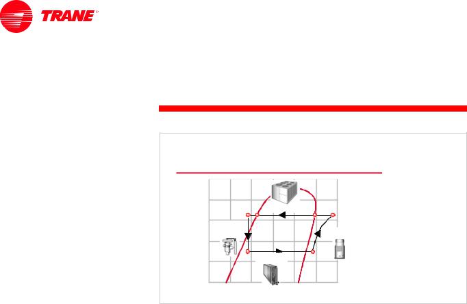
The pressure–enthalpy (P–h) chart plots the properties of a refrigerant: refrigerant pressure (vertical axis) versus enthalpy, or heat content (horizontal axis). A diagram of the basic vapor-compression refrigeration cycle can be superimposed on a pressure–enthalpy chart to demonstrate the function of each component in the system.
Refrigerant enters the evaporator in the form of a cool, low-pressure mixture of liquid and vapor (A). Heat is transferred from the relatively warm air or water to be cooled to the refrigerant, causing the liquid refrigerant to boil and in some cases superheat (B). The resulting vapor (B) is then pumped from the evaporator by the compressor, which increases the pressure and temperature of the refrigerant vapor. Notice that during the compression process (B to C), the heat content (enthalpy) of the vapor is increased. The mechanical energy used by the compressor to increase the pressure of the refrigerant vapor is converted to heat energy, called the heat of compression. This causes the temperature of the refrigerant to also rise as the pressure is increased.
The resulting hot, high-pressure refrigerant vapor (C) enters the condenser where heat is transferred to ambient air or water at a lower temperature. Inside the condenser, the refrigerant desuperheats (C to D), condenses into a liquid (D to E), and, in some cases, subcools (E to F). The refrigerant pressure inside the condenser is determined by the temperature of the air or water that is available as the condensing media.
This liquid refrigerant (F) then flows from the condenser to the expansion device. The expansion device creates a pressure drop that reduces the pressure of the refrigerant to that of the evaporator. At this low pressure, a small portion of the refrigerant boils (or flashes), cooling the remaining liquid refrigerant to the desired evaporator temperature (A). The cool mixture of liquid and vapor refrigerant travels to the evaporator to repeat the cycle.
2 |
TRG-TRC004-EN |

period one
Compressor Types
notes
5HIULJHUDWLRQ &RPSUHVVRUV
SHULRG RQH
&RPSUHVVRU 7\SHV
Figure 4
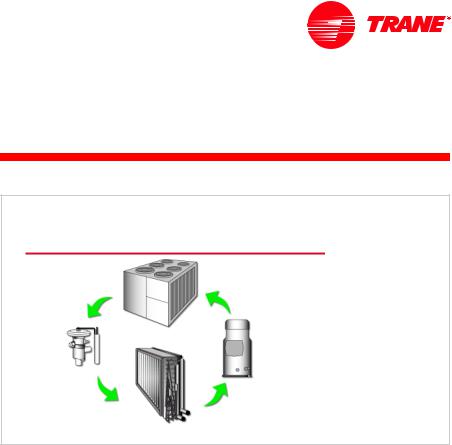
This period is devoted to the discussion of the different types of compressors.
VFUROO
UHFLSURFDWLQJ
KHOLFDO URWDU\ |
FHQWULIXJDO |
Figure 5 |
|
||
|
|
There are primarily four types of compressors used in the air-conditioning industry: reciprocating, scroll, helical-rotary (or screw), and centrifugal.
The traditional reciprocating compressor has been used in the industry for decades. It contains cylinders, pistons, rods, a crankshaft, and valves, similar to an automobile engine. Refrigerant is drawn into the cylinders on the downstroke of the piston and compressed on the upstroke.
Scroll and helical-rotary (or screw) compressors have become more common, replacing the reciprocating compressor in most applications due to their improved reliability and efficiency.
These three types of compressors (reciprocating, scroll, and helical-rotary) all work on the principle of trapping the refrigerant vapor and compressing it by
TRG-TRC004-EN |
3 |
period one
Compressor Types
notes
gradually shrinking the volume of the refrigerant. Thus, they are called positive-displacement compressors.
In contrast, centrifugal compressors use the principle of dynamic compression, which involves converting energy from one form to another in order to increase the pressure and temperature of the refrigerant. The centrifugal compressor uses centrifugal force, generated by a rotating impeller, to compress the refrigerant vapor.
5HFLSURFDWLQJ &RPSUHVVRU
|
|
|
LQWDNH |
|
|
|
|
VWURNH |
|
GLVFKDUJH |
|
|
|
|
YDOYH |
|
|
|
VXFWLRQ |
|
|
|
|
|
|
|
|
|
YDOYH |
UHIULJHUDQW |
|
|
|
SLVWRQ |
|
|
|
||
YDSRU |
URG |
|||
|
||||
|
|
F\OLQGHU |
||
Figure 6
Reciprocating Compressor
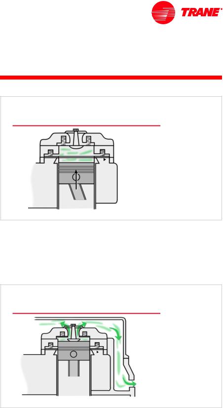
The first type of compressor to be discussed is the reciprocating compressor. The principles of operation for all reciprocating compressors are fundamentally the same. The refrigerant vapor is compressed by a piston that is located inside a cylinder, similar to the engine in an automobile. A fine layer of oil prevents the refrigerant vapor from escaping through the mating surfaces. The piston is connected to the crankshaft by a rod. As the crankshaft rotates, it causes the piston to travel back and forth inside the cylinder. This motion is used to draw refrigerant vapor into the cylinder, compress it, and discharge it from the cylinder. A pair of valves, the suction valve and the discharge valve, are used to trap the refrigerant vapor within the cylinder during this process. In the example reciprocating compressor shown, the spring-actuated valves are O-shaped, allowing them to cover the valve openings around the outside of the cylinder while the piston travels through the middle.
During the intake stroke of the compressor, the piston travels away from the discharge valve and creates a vacuum effect, reducing the pressure within the cylinder to below suction pressure. Since the pressure within the cylinder is less than the pressure of the refrigerant at the suction side of the compressor, the suction valve is forced open and the refrigerant vapor is drawn into the cylinder.
4 |
TRG-TRC004-EN |
period one
Compressor Types
notes
5HFLSURFDWLQJ &RPSUHVVRU
FRPSUHVVLRQ
VWURNH
GLVFKDUJH 
YDOYH
 VXFWLRQ
YDOYH
Figure 7
During the compression stroke, the piston reverses its direction and travels toward the discharge valve, compressing the refrigerant vapor and increasing the pressure within the cylinder. When the pressure inside the cylinder exceeds the suction pressure, the suction valve is forced closed, trapping the refrigerant vapor inside the cylinder.
As the piston continues to travel toward the discharge valve, the refrigerant vapor is compressed, increasing the pressure inside the cylinder.
5HFLSURFDWLQJ &RPSUHVVRU
KHDGVSDFH
GLVFKDUJH 
YDOYH
 VXFWLRQ
YDOYH
GLVFKDUJH
RSHQLQJ
Figure 8
When the pressure within the cylinder exceeds the discharge (or head) pressure, the discharge valve is forced open, allowing the compressed refrigerant vapor to leave the cylinder. The compressed refrigerant travels through the headspace and leaves the compressor through the discharge opening.
TRG-TRC004-EN |
5 |
period one
Compressor Types
notes
5HFLSURFDWLQJ &RPSUHVVRU
VXFWLRQ |
F\OLQGHU |
KHDGVSDFH |
RSHQLQJ |
|
|
GLVFKDUJH
RSHQLQJ
SLVWRQ
URG
PRWRU |
FUDQNVKDIW |
Figure 9
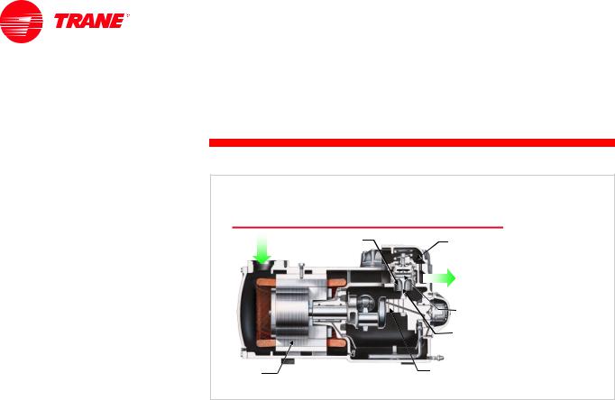
In the reciprocating compressor shown, the refrigerant vapor from the suction line enters the compressor through the suction opening. It then passes around and through the motor, cooling the motor, before it enters the cylinder to be compressed. The compressed refrigerant leaves the cylinder, travels through the headspace, and leaves the compressor through the discharge opening.
Most reciprocating compressors have multiple piston–cylinder pairs attached to a single crankshaft.
In the air-conditioning industry, reciprocating compressors were widely used in all types of refrigeration equipment. As mentioned earlier, however, scroll and helical-rotary compressors have become more common, replacing the reciprocating compressor in most of these applications because of their improved reliability and efficiency.
6 |
TRG-TRC004-EN |
period one
Compressor Types
notes
6FUROO &RPSUHVVRU
VWDWLRQDU\
VFUROO
|
GLVFKDUJH |
GLVFKDUJH |
|
SRUW |
|
LQWDNH |
LQWDNH |
|
PRWRU |
GULYHQ |
VKDIW |
VFUROO |
|
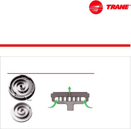
Figure 10
Scroll Compressor
Similar to the reciprocating compressor, the scroll compressor works on the principle of trapping the refrigerant vapor and compressing it by gradually shrinking the volume of the refrigerant. The scroll compressor uses two scroll configurations, mated face-to-face, to perform this compression process. The tips of the scrolls are fitted with seals that, along with a fine layer of oil, prevent the compressed refrigerant vapor from escaping through the mating surfaces.
The upper scroll, called the stationary scroll, contains a discharge port. The lower scroll, called the driven scroll, is connected to a motor by a shaft and bearing assembly. The refrigerant vapor enters through the outer edge of the scroll assembly and discharges through the port at the center of the stationary scroll.
TRG-TRC004-EN |
7 |

period one
Compressor Types
notes
6FUROO &RPSUHVVRU
MRXUQDO |
PRWRU |
EHDULQJ |
VKDIW |
GLUHFWLRQ
RI URWDWLRQ
 GULYHQ
VFUROO
Figure 11
The center of the scroll journal bearing and the center of the motor shaft are offset. This offset imparts an orbiting motion to the driven scroll. Rotation of the motor shaft causes the scroll to orbit—not rotate—about the shaft center.
6FUROO &RPSUHVVRU
LQWDNH
GLVFKDUJH
SRUW
LQWDNH
Figure 12
This orbiting motion causes the mated scrolls to form pockets of refrigerant vapor. As the orbiting motion continues, the relative movement between the orbiting scroll and the stationary scroll causes the pockets to move toward the discharge port at the center of the assembly, gradually decreasing the refrigerant volume and increasing the pressure.
Three revolutions of the motor shaft are required to complete the compression process.
8 |
TRG-TRC004-EN |

period one
Compressor Types
notes
6FUROO &RPSUHVVRU
LQWDNH
SKDVH
FRPSUHVVLRQ
SKDVH
GLVFKDUJH
SKDVH
Figure 13
During the first full revolution of the shaft, or the intake phase, the edges of the scrolls separate, allowing the refrigerant vapor to enter the space between the two scrolls. By the completion of first revolution, the edges of the scrolls meet again, forming two closed pockets of refrigerant.
During the second full revolution, or the compression phase, the volume of each pocket is progressively reduced, increasing the pressure of the trapped refrigerant vapor. Completion of the second revolution produces nearmaximum compression.
During the third full revolution, or the discharge phase, the interior edges of the scrolls separate, releasing the compressed refrigerant through the discharge port. At the completion of the revolution, the volume of each pocket is reduced to zero, forcing the remaining refrigerant vapor out of the scrolls.
Looking at the complete cycle, notice that these three phases—intake, compression, and discharge—occur simultaneously in an ongoing sequence. While one pair of these pockets is being formed, another pair is being compressed and a third pair is being discharged.
TRG-TRC004-EN |
9 |

period one
Compressor Types
notes
6FUROO &RPSUHVVRU
GRPH
 GLVFKDUJH
 RSHQLQJ
VFUROOV
PRWRU 
VXFWLRQ
 RSHQLQJ
Figure 14
In this example scroll compressor, refrigerant vapor enters through the suction opening. The refrigerant then passes through a gap in the motor, cooling the motor, before entering the compressor housing. The refrigerant vapor is drawn into the scroll assembly where it is compressed, discharged into the dome, and finally discharged out of the compressor through the discharge opening.
In the air-conditioning industry, scroll compressors are widely used in heat pumps, rooftop units, split systems, self-contained units, and even small water chillers.
+HOLFDO 5RWDU\ 6FUHZ &RPSUHVVRU
Figure 15
Helical-Rotary (Screw) Compressor
Similar to the scroll compressor, the helical-rotary compressor traps the refrigerant vapor and compresses it by gradually shrinking the volume of the refrigerant. This particular helical-rotary compressor design uses two mating screw-like rotors to perform the compression process.
10 |
TRG-TRC004-EN |
 Loading...