


 Loading...
Trane S9V2B040U3PSBA, S9V2B060U3PSBA, S9V2B060U4PSBA, S9V2B080U3PSBA, S9V2B080U4PSBA Specification Sheet
...Product Data
Upflow/ Horizontal Left/Right, Downflow
Two Stage Condensing
Gas Fired Furnace
Upflow, Convertible to |
Downflow Only |
Horizontal Right or |
S9V2B040D3PSBA |
Horizontal Left |
S9V2B060D3PSBA |
S9V2B040U3PSBA |
S9V2B080D3PSBA |
S9V2B060U3PSBA |
S9V2B080D4PSBA |
S9V2B060U4PSBA |
S9V2C100D4PSBA |
S9V2B080U3PSBA |
S9V2C100D5PSBA |
S9V2B080U4PSBA |
S9V2D120D5PSBA |
S9V2C080U5PSBA |
|
S9V2C100U4PSBA |
|
S9V2C100U5PSBA |
|
S9V2D120U5PSBA |
|
Note: Graphics in this document are for representation only. Actual model may differ in appearance.
March 2017 |
22-1921-1C-EN |

General Features
NATURAL GAS MODELS
Central Heating furnace designs are certified by the American Gas Association for both natural and L.P. gas. Limit setting and rating data were established and approved under standard rating conditions using American National Standards Institute standards.
SAFE OPERATION
The Integrated System Control is a solid state device which continuously monitors for presence of flame when the system is in the heating mode of operation. Dual solenoid combination gas valve and regulator provide additional safety.
QUICK HEATING
Durable, cycle tested, heavy gauge tubular stainless steel primary heat exchanger quickly transfers heat to provide warm conditioned air to the structure. Low energy power vent blower, to increase efficiency and provide a positive discharge of gas fumes to the outside.
BURNERS
Multiport Inshot burners will give years of quiet and efficient service. All models can be converted to L.P. gas with LP conversion kit.
INTEGRATED SYSTEM CONTROL
Exclusively designed operational program provides total control of furnace limit sensors, blowers, gas valve, flame control and includes self diagnostics for ease of service. Also contains dry contacts for EAC and HUM.
ENERGY EFFICIENT OPERATION
Furnace is certified by the manufacturer to leak 1% or less of nominal air conditioning CFM delivered when pressurized to .5" water column with all inlets, outlets, and drains sealed.
AIR DELIVERY
The variable speed blower motor has sufficient airflow for most heating and cooling requirements and will switch from heating to cooling speeds on demand from room thermostat.
SECONDARY HEAT EXCHANGER
The S-Series furnace has a special type 294C™ stainless steel secondary heat exchanger to reclaim heat from flue gases which would normally be lost.
STYLING
Heavy gauge steel and "wrap-around" cabinet construction on enamel finish for strength and beauty. Every orientation has There are no knockouts on cabinet.
FEATURES AND GENERAL OPERATION
is used in the cabinet with bakedat least two venting options.
The S-Series furnace utilizes a Silicon Nitride Hot Surface Ignition system, which eliminates the waste of a constant burning pilot. The integrated system control lights the main burners upon a demand for heat from the room thermostat. Complete front service access.
a.Low energy power venter
b.Vent proving pressure switches.
2 |
22-1921-1C-EN |

Features and Benefits
96.0% AFUE ACROSS ALL MODELS
Meets utility rebates
Lowers utility bills
ELECTRICALLY EFFICIENT
Efficient airflow design reduces electrical energy use
34 INCH TALL
Lighter, easier to move and fit into tight spaces like short basements or tight closets
Works great with larger, high-efficiency coils
No knockouts
3–WAY MULTI-POISE / DEDICATED DOWNFLOW
9 SKU’s — Upflow / Horizontal Left / Horizontal Right
7 SKU’s — Downflow
Added application flexibility and reduction in specification errors
AIRFLOW
At least 400 CFM/ton at 0.5 in. H20 external static pressure; setup airflow options down to 290 CFM/ton
REGULATORY
All models are air tight; 1% or less air leakage as per ASHRAE 193
Open vestibule design provides a full 34” high open vestibule
DIMENSIONS
Widths are industry standard: 17.5”, 21”, and 24.5”
Depth remains approximately 28”
Cabinet will be compatible with industry standard coils, as well as, other accessories
INTEGRATED FURNACE CONTROL
Setup / Status / Diagnostics / Digital Display
No dip switches
Last six errors stored
Dry contact EAC and HUM connections
All Molex connections; no spade terminals
Low voltage labeled above and below
Rain shield over IFC keeps condensate off the control
TUBULAR STAINLESS STEEL PRIMARY HEAT EXCHANGER 29–4C STAINLESS STEEL SECONDARY HEAT EXCHANGER
Stainless steel is a more durable, corrosive-resistant material than aluminumized steel
Integrated rail system for easy access if required
Reduces or eliminates need for baffles
VORTICA II BLOWER, DESIGNED EXCLUSIVELY FOR THE S-SERIES FURNACE
Improved airflow efficiency
Durable, easy to clean, two piece housing
Single piece belly band/ motor arm assembly
Blower deck has full-length rails for easy removal and replacement, regardless of poise
22-1921-1C-EN |
3 |

Features and Benefits
THREE–WAY MULTI-POISE (UPFLOW, HORIZONTAL LEFT AND RIGHT) PLUS DEDICATED DOWNFLOW
Easier to specify
Shipped ready to install (no kits required)
Every model has at least two venting options
When in horizontal, trap extends only about 2”
Barbed fitting on trap at hose connection and on cabinet transition for hose has barbed fitting and clamps at both ends for leak resistance.
Vent table improvements including longer vent lengths; 2” pipe can be used up to 100K
4 |
22-1921-1C-EN |
Accessories
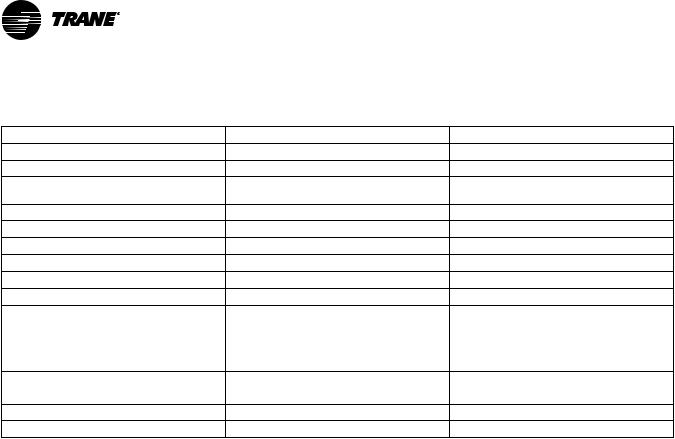
Table 1. Accessories
Model Number |
Description |
Use with |
BAYHANG |
Horizontal Hanging Kit |
All Upflow Furnaces |
BAYVENT200B |
Sidewall Vent Termination Kit |
All Furnaces |
BAYVENTCN200B |
Sidewall Vent Termination Kit (Canada — |
All Furnaces |
|
CPVC) |
|
BAYAIR30AVENTA |
Concentric Vent Kit |
All Furnaces |
BAYAIR30CNVENT |
Concentric Vent Kit (Canada — CPVC) |
All Furnaces |
BAYREDUCE |
Reducing Coupling (CPVC) |
All Furnaces |
BAYLIFTB |
Dual Return Kit (B size extension) |
B Cabinet Upflow Furnaces |
BAYLIFTC |
Dual Return Kit (C size extension) |
C Cabinet Upflow Furnaces |
BAYLIFTD |
Dual Return Kit (D size extension) |
D Cabinet Upflow Furnaces |
BAYBASE205 |
Downflow Subbase |
All Downflow Furnaces |
BAYFLTR206 |
Filter Access Door Kit (Downflow only) |
All Upflow Furnaces |
BAYSLF1165AA (a) |
1” SlimFit Box with MERV 4 Filter |
All Upflow Furnaces |
BAYFLTR203 |
Horizontal Filter Kit |
B Cabinet Furnaces in Downflow/Horizontal |
BAYFLTR204 |
Horizontal Filter Kit |
C Cabinet Furnaces in Downflow/Horizontal |
BAYFLTR205 |
Horizontal Filter Kit |
D Cabinet Furnaces in Downflow/Horizontal |
BAYLPSS400A |
LP Conversion Kit with Stainless Steel Burners |
All Furnaces |
BAYMFGH200A |
Manufactured/Mobile Housing Kit |
All Furnaces |
(a) Airflow greater than 1600 CFM requires dual returns
22-1921-1C-EN |
5 |
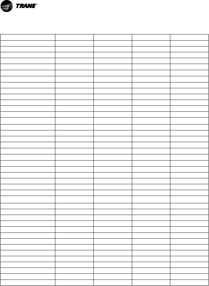
Product Specification
MODEL |
S9V2B040U3PSBA (a) |
S9V2B060U3PSBA(a) |
S9V2B060U4PSBA(a) |
S9V2B080U3PSBA(a) |
|
TYPE |
Upflow/Horizontal |
Upflow/Horizontal |
Upflow/Horizontal |
Upflow / Horizontal |
|
RATINGS (b) |
|
|
|
|
|
1st Stage Input BTUH (ICS) |
26,000 |
39,000 |
39,000 |
52,000 |
|
1st Stage Capacity BTUH |
25,220 |
37,830 |
37,830 |
50,440 |
|
2nd Stage Input BTUH |
40,000 |
60,000 |
60,000 |
80,000 |
|
2nd Stage Capacity BTUH (ICS) (c) (d) |
38,800 |
58,200 |
58,200 |
77,600 |
|
1st StageTemp. Rise (Min.-Max.) |
25 - 55 |
25 - 55 |
25 - 55 |
30 - 60 |
|
2nd StageTemp. Rise (Min.-Max.) |
30 - 60 |
35 - 65 |
35 - 65 |
40 - 70 |
|
AFUE (%) (c)(d) |
96.0 |
96.0 |
96.0 |
96.0 |
|
BLOWER DRIVE |
DIRECT |
DIRECT |
DIRECT |
DIRECT |
|
Diameter — Width (In.) |
11 X 8 |
11 X 8 |
11 X 8 |
11 X 8 |
|
No. Used |
1 |
1 |
1 |
1 |
|
Speeds (No.) |
Variable |
Variable |
Variable |
Variable |
|
CFM vs. in. w.g. |
See Fan Performance |
See Fan Performance |
See Fan Performance |
See Fan Performance |
|
Table |
Table |
Table |
Table |
||
|
|||||
Motor HP |
1/2 |
1/2 |
3/4 |
1/2 |
|
RPM |
Variable |
Variable |
Variable |
Variable |
|
Volts/Ph/Hz |
120 / 1 / 60 |
120 / 1 / 60 |
120 / 1 / 60 |
120 / 1 / 60 |
|
FLA |
5.7 |
5.7 |
8.0 |
5.7 |
|
COMBUSTION FAN — Type |
Centrifugal |
Centrifugal |
Centrifugal |
Centrifugal |
|
Drive — No. Speeds |
Direct - 2 |
Direct - 2 |
Direct - 2 |
Direct - 2 |
|
Motor HP — RPM |
3300/2600 |
3300/2600 |
3300/2600 |
3300/2600 |
|
Volts/Ph/Hz |
120 / 1 / 60 |
120 / 1 / 60 |
120 / 1 / 60 |
120 / 1 / 60 |
|
FLA |
0.66 |
0.66 |
0.66 |
0.66 |
|
FILTER — Furnished? |
No |
No |
No |
No |
|
Type recommended |
High Velocity |
High Velocity |
High Velocity |
High Velocity |
|
Hi Vel. (No.-Size-Thk.) |
1 — 16x25 — 1 in. |
1 — 16x25 — 1 in. |
1 — 16x25 — 1 in. |
1 — 16x25 — 1 in. |
|
VENT PIPE DIAMETER — Min (in.) |
2 Round |
2 Round |
2 Round |
2 Round |
|
(e) (f) |
|||||
HEAT EXCHANGER |
|
|
|
|
|
Type — Fired |
409 Stainless Steel |
409 Stainless Steel |
409 Stainless Steel |
409 Stainless Steel |
|
— Unfired |
29–4C Stainless Steel |
29–4C Stainless Steel |
29–4C Stainless Steel |
29–4C Stainless Steel |
|
Gauge (Fired) |
20 |
20 |
20 |
20 |
|
ORIFICES — Main |
|
|
|
|
|
Nat. Gas Qty. — Drill Size |
2- 45 |
3 - 45 |
3 - 45 |
4 - 45 |
|
LP Gas Qty. — Drill Size |
2- 56 |
3 - 56 |
3 - 56 |
4 - 56 |
|
GAS VALVE |
Redundant -Two Stage |
Redundant -Two Stage |
Redundant -Two Stage |
Redundant -Two Stage |
|
PILOT SAFETY DEVICE |
|
|
|
|
|
Type |
120 V SiNi Igniter |
120 V SiNi Igniter |
120 V SiNi Igniter |
120 V SiNi Igniter |
|
BURNERS — Type |
Multiport Inshot |
Multiport Inshot |
Multiport Inshot |
Multiport Inshot |
|
Number |
2 |
3 |
3 |
4 |
|
POWER CONN. — V/Ph/Hz (g) |
120 / 1 / 60 |
120 / 1 / 60 |
120 / 1 / 60 |
120 / 1 / 60 |
|
Ampacity (In Amps) |
7.9 |
7.9 |
10.8 |
7.9 |
6 |
22-1921-1C-EN |
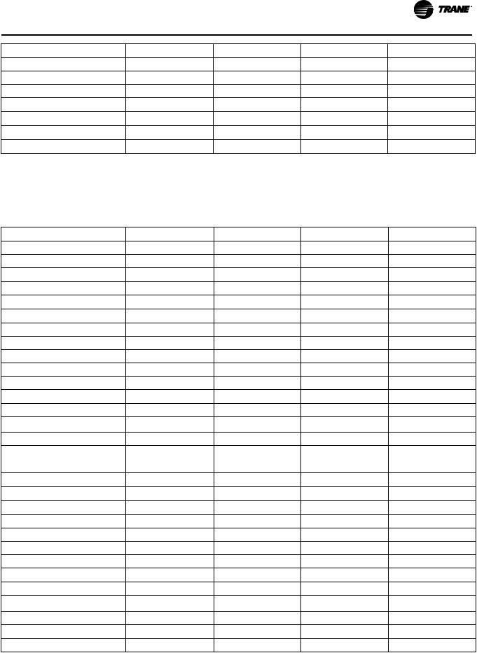
Product Specification
MODEL |
S9V2B040U3PSBA (a) |
S9V2B060U3PSBA(a) |
S9V2B060U4PSBA(a) |
S9V2B080U3PSBA(a) |
Max. Overcurrent Protection (Amps) |
15 |
15 |
15 |
15 |
PIPE CONN. SIZE (in.) |
1/2 |
1/2 |
1/2 |
1/2 |
DIMENSIONS |
H x W x D |
H x W x D |
H x W x D |
H x W x D |
Uncrated (In.) |
34 x 17-1/2 x 28–3/4 |
34 x 17-1/2 x 28–3/4 |
34 x 17-1/2 x 28–3/4 |
34 x 17-1/2 x 28–3/4 |
Crated (In.) |
35-1/2 x 19-1/2 x 30-7/8 |
35-1/2 x 19-1/2 x 30-7/8 |
35-1/2 x 19-1/2 x 30-7/8 |
35-1/2 x 19-1/2 x 30-7/8 |
WEIGHT |
|
|
|
|
Shipping (Lbs.)/Net (Lbs.) |
122/114 |
127/119 |
130/122 |
132/124 |
(a)Meets Energy Star
(b)For U.S. applications, above input ratings (BTUH) are up to 2,000 feet, derate 4% per 1,000 feet for elevations above 2,000 feet above sea level. For Canadian applications, above input ratings (BTUH) are up to 4,500 feet, derate 4% per 1,000 feet for elevations above 4,500 feet above sea level.
(c)Central Furnace heating designs are certified to ANSI Z21.47 / CSA 2.3 — latest edition.
(d)Based on U.S. government standard tests.
(e)Refer to the Vent Length Table in the Installer's Guide.
(f)All S9V2 furnace models have a vent outlet diameter that equals 2 in.
(g)The above wiring specifications are in accordance with National Electrical Code; however, installations must comply with local codes.
MODEL |
S9V2B080U4PSBA (a) |
S9V2C080U5PSBA(a) S9V2C100U4PSBA(a) S9V2C100U5PSBA(a) |
|||
TYPE |
Upflow/Horizontal |
Upflow/Horizontal |
Upflow/Horizontal |
Upflow / Horizontal |
|
RATINGS (b) |
|
|
|
|
|
1st Stage Input BTUH (ICS) |
52,000 |
52,000 |
65,000 |
65,000 |
|
1st Stage Capacity BTUH |
50,440 |
50,440 |
63,050 |
63,050 |
|
2nd Stage Input BTUH |
80,000 |
80,000 |
100,000 |
100,000 |
|
2nd Stage Capacity BTUH (ICS) (c) (d) |
77,600 |
77,600 |
97,000 |
97,000 |
|
1st StageTemp. Rise (Min.-Max.) |
30 - 60 |
30 - 60 |
25 - 55 |
25 - 55 |
|
2nd StageTemp. Rise (Min.-Max.) |
35 - 65 |
35 - 65 |
35 - 65 |
30 - 60 |
|
AFUE (%) (c)(d) |
96.0 |
96.0 |
96.0 |
96.0 |
|
BLOWER DRIVE |
DIRECT |
DIRECT |
DIRECT |
DIRECT |
|
Diameter — Width (In.) |
11 X 8 |
11 X 10 |
11 X 10 |
11 X 10 |
|
No. Used |
1 |
1 |
1 |
1 |
|
Speeds (No.) |
Variable |
Variable |
Variable |
Variable |
|
CFM vs. in. w.g. |
See Fan Performance |
See Fan Performance |
See Fan Performance |
See Fan Performance |
|
Table |
Table |
Table |
Table |
||
|
|||||
Motor HP |
3/4 |
1 |
3/4 |
1 |
|
RPM |
Variable |
Variable |
Variable |
Variable |
|
Volts/Ph/Hz |
120 / 1 / 60 |
120 / 1 / 60 |
120 / 1 / 60 |
120 / 1 / 60 |
|
FLA |
8.0 |
10.5 |
8.0 |
10.5 |
|
COMBUSTION FAN — Type |
Centrifugal |
Centrifugal |
Centrifugal |
Centrifugal |
|
Drive — No. Speeds |
Direct - 2 |
Direct - 2 |
Direct - 2 |
Direct - 2 |
|
Motor HP — RPM |
3300/2600 |
3300/2600 |
3300/2600 |
3300/2600 |
|
Volts/Ph/Hz |
120 / 1 / 60 |
120 / 1 / 60 |
120 / 1 / 60 |
120 / 1 / 60 |
|
FLA |
0.66 |
0.66 |
0.66 |
0.66 |
|
FILTER — Furnished? |
No |
No |
No |
No |
|
Type recommended |
High Velocity |
High Velocity |
High Velocity |
High Velocity |
|
Hi Vel. (No.-Size-Thk.) |
1 — 16x25 — 1 in. |
1 — 20x25 — 1 in. |
1 — 20x25 — 1 in. |
1 — 20x25 — 1 in. |
|
VENT PIPE DIAMETER — Min (in.) |
2 Round |
2 Round |
2 Round |
2 Round |
|
(e) (f) |
|||||
HEAT EXCHANGER |
|
|
|
|
|
Type — Fired |
409 Stainless Steel |
409 Stainless Steel |
409 Stainless Steel |
409 Stainless Steel |
|
— Unfired |
29–4C Stainless Steel |
29–4C Stainless Steel |
29–4C Stainless Steel |
29–4C Stainless Steel |
|
22-1921-1C-EN |
7 |
Product Specification
MODEL |
S9V2B080U4PSBA (a) |
S9V2C080U5PSBA(a) |
S9V2C100U4PSBA(a) |
S9V2C100U5PSBA(a) |
Gauge (Fired) |
20 |
20 |
20 |
20 |
ORIFICES — Main |
|
|
|
|
Nat. Gas Qty. — Drill Size |
4 - 45 |
4 - 45 |
5 - 45 |
5 - 45 |
LP Gas Qty. — Drill Size |
4- 56 |
4- 56 |
5- 56 |
5- 56 |
GAS VALVE |
Redundant -Two Stage |
Redundant -Two Stage |
Redundant -Two Stage |
Redundant -Two Stage |
PILOT SAFETY DEVICE |
|
|
|
|
Type |
120 V SiNi Igniter |
120 V SiNi Igniter |
120 V SiNi Igniter |
120 V SiNi Igniter |
BURNERS — Type |
Multiport Inshot |
Multiport Inshot |
Multiport Inshot |
Multiport Inshot |
Number |
4 |
4 |
5 |
5 |
POWER CONN. — V/Ph/Hz (g) |
120 / 1 / 60 |
120 / 1 / 60 |
120 / 1 / 60 |
120 / 1 / 60 |
Ampacity (In Amps) |
10.8 |
13.9 |
10.8 |
13.9 |
Max. Overcurrent Protection (Amps) |
15 |
15 |
15 |
15 |
PIPE CONN. SIZE (in.) |
1/2 |
1/2 |
1/2 |
1/2 |
DIMENSIONS |
H x W x D |
H x W x D |
H x W x D |
H x W x D |
Uncrated (In.) |
34 x 17-1/2 x 28–3/4 |
34 x 21 x 28–3/4 |
34 x 21 x 28–3/4 |
34 x 21 x 28–3/4 |
Crated (In.) |
35-1/2 x 19-1/2 x 30-7/8 |
35-1/2 x 23 x 30-7/8 |
35-1/2 x 23 x 30-7/8 |
35-1/2 x 23 x 30-7/8 |
WEIGHT |
|
|
|
|
Shipping (Lbs.)/Net (Lbs.) |
135/127 |
149/139 |
154/144 |
155/145 |
(a)Meets Energy Star
(b)For U.S. applications, above input ratings (BTUH) are up to 2,000 feet, derate 4% per 1,000 feet for elevations above 2,000 feet above sea level. For Canadian applications, above input ratings (BTUH) are up to 4,500 feet, derate 4% per 1,000 feet for elevations above 4,500 feet above sea level.
(c)Central Furnace heating designs are certified to ANSI Z21.47 / CSA 2.3 — latest edition.
(d)Based on U.S. government standard tests.
(e)Refer to the Vent Length Table in the Installer's Guide.
(f)All S9V2 furnace models have a vent outlet diameter that equals 2 in.
(g)The above wiring specifications are in accordance with National Electrical Code; however, installations must comply with local codes.
MODEL |
S9V2D120U5PSBA (a) |
S9V2B040D3PSBA(a) |
S9V2B060D3PSBA(a) |
S9V2B080D3PSBA(a) |
|
TYPE |
Upflow/Horizontal |
Downflow |
Downflow |
Downflow |
|
RATINGS (b) |
|
|
|
|
|
1st Stage Input BTUH (ICS) |
78,000 |
26,000 |
39,000 |
52,000 |
|
1st Stage Capacity BTUH |
75,660 |
25,220 |
37,830 |
50,440 |
|
2nd Stage Input BTUH |
120,000 |
40,000 |
60,000 |
80,000 |
|
2nd Stage Capacity BTUH (ICS) (c) (d) |
116,400 |
38,800 |
58,200 |
77,600 |
|
1st StageTemp. Rise (Min.-Max.) |
35-65 |
25 - 55 |
25 - 55 |
30 - 60 |
|
2nd StageTemp. Rise (Min.-Max.) |
40-70 |
30 - 60 |
35 - 65 |
40 - 70 |
|
AFUE (%) (c)(d) |
96.0 |
96.0 |
96.0 |
96.0 |
|
BLOWER DRIVE |
DIRECT |
DIRECT |
DIRECT |
DIRECT |
|
Diameter — Width (In.) |
11 X 10 |
11 X 8 |
11 X 8 |
11 X 8 |
|
No. Used |
1 |
1 |
1 |
1 |
|
Speeds (No.) |
Variable |
Variable |
Variable |
Variable |
|
CFM vs. in. w.g. |
See Fan Performance |
See Fan Performance |
See Fan Performance |
See Fan Performance |
|
Table |
Table |
Table |
Table |
||
|
|||||
Motor HP |
1 |
1/2 |
1/2 |
1/2 |
|
RPM |
Variable |
Variable |
Variable |
Variable |
|
Volts/Ph/Hz |
120 / 1 / 60 |
120 / 1 / 60 |
120 / 1 / 60 |
120 / 1 / 60 |
|
FLA |
10.5 |
5.7 |
5.7 |
5.7 |
|
COMBUSTION FAN — Type |
Centrifugal |
Centrifugal |
Centrifugal |
Centrifugal |
8 |
22-1921-1C-EN |
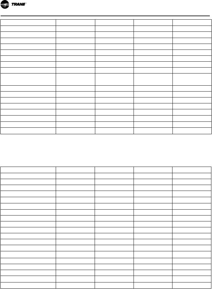
Product Specification
MODEL |
S9V2D120U5PSBA (a) |
S9V2B040D3PSBA(a) |
S9V2B060D3PSBA(a) |
S9V2B080D3PSBA(a) |
Drive — No. Speeds |
Direct - 2 |
Direct - 2 |
Direct - 2 |
Direct - 2 |
Motor HP — RPM |
3300/2600 |
3300/2600 |
3300/2600 |
3300/2600 |
Volts/Ph/Hz |
120 / 1 / 60 |
120 / 1 / 60 |
120 / 1 / 60 |
120 / 1 / 60 |
FLA |
0.66 |
0.66 |
0.66 |
0.66 |
FILTER — Furnished? |
No |
No |
No |
No |
Type recommended |
High Velocity |
High Velocity |
High Velocity |
High Velocity |
Hi Vel. (No.-Size-Thk.) |
1 — 24x25 — 1 in. |
2 — 14x20 — 1 in. |
2 — 14x20 — 1 in. |
2 — 14x20 — 1 in. |
VENT PIPE DIAMETER — Min (in.) |
3 Round |
2 Round |
2 Round |
2 Round |
(e) (f) |
||||
HEAT EXCHANGER |
|
|
|
|
Type — Fired |
409 Stainless Steel |
409 Stainless Steel |
409 Stainless Steel |
409 Stainless Steel |
— Unfired |
29–4C Stainless Steel |
29–4C Stainless Steel |
29–4C Stainless Steel |
29–4C Stainless Steel |
Gauge (Fired) |
20 |
20 |
20 |
20 |
ORIFICES — Main |
|
|
|
|
Nat. Gas Qty. — Drill Size |
6 - 45 |
2- 45 |
3 - 45 |
4 - 45 |
LP Gas Qty. — Drill Size |
6- 56 |
2- 56 |
3 - 56 |
4 - 56 |
GAS VALVE |
Redundant -Two Stage |
Redundant -Two Stage |
Redundant -Two Stage |
Redundant -Two Stage |
PILOT SAFETY DEVICE |
|
|
|
|
Type |
120 V SiNi Igniter |
120 V SiNi Igniter |
120 V SiNi Igniter |
120 V SiNi Igniter |
BURNERS — Type |
Multiport Inshot |
Multiport Inshot |
Multiport Inshot |
Multiport Inshot |
Number |
6 |
2 |
3 |
4 |
POWER CONN. — V/Ph/Hz (g) |
120 / 1 / 60 |
120 / 1 / 60 |
120 / 1 / 60 |
120 / 1 / 60 |
Ampacity (In Amps) |
13.9 |
7.9 |
7.9 |
7.9 |
Max. Overcurrent Protection (Amps) |
15 |
15 |
15 |
15 |
PIPE CONN. SIZE (in.) |
1/2 |
1/2 |
1/2 |
1/2 |
DIMENSIONS |
H x W x D |
H x W x D |
H x W x D |
H x W x D |
Uncrated (In.) |
34 x 24-1/2 x 28–3/4 |
34 x 17-1/2 x 28–3/4 |
34 x 17-1/2 x 28–3/4 |
34 x 17-1/2 x 28–3/4 |
Crated (In.) |
35-1/2 x 26-1/2 x 30-7/8 |
35-1/2 x 19-1/2 x 30-7/8 |
35-1/2 x 19-1/2 x 30-7/8 |
35-1/2 x 19-1/2 x 30-7/8 |
WEIGHT |
|
|
|
|
Shipping (Lbs.)/Net (Lbs.) |
167/156 |
122/114 |
127/119 |
132/124 |
(a)Meets Energy Star
(b)For U.S. applications, above input ratings (BTUH) are up to 2,000 feet, derate 4% per 1,000 feet for elevations above 2,000 feet above sea level. For Canadian applications, above input ratings (BTUH) are up to 4,500 feet, derate 4% per 1,000 feet for elevations above 4,500 feet above sea level.
(c)Central Furnace heating designs are certified to ANSI Z21.47 / CSA 2.3.
(d)Based on U.S. government standard tests.
(e)Refer to the Vent Length Table in the Installer's Guide.
(f)All S9V2 furnace models have a vent outlet diameter that equals 2 in.
(g)The above wiring specifications are in accordance with National Electrical Code; however, installations must comply with local codes.
22-1921-1C-EN |
9 |

Product Specification
MODEL |
S9V2B080D4PSBA (a) |
S9V2C100D4PSBA(a) |
S9V2C100D5PSBA(a) |
S9V2D120D5PSBA(a) |
|
TYPE |
Downflow |
Downflow |
Downflow |
Downflow |
|
RATINGS (b) |
|
|
|
|
|
1st Stage Input BTUH (ICS) |
52,000 |
65,000 |
65,000 |
78,000 |
|
1st Stage Capacity BTUH |
50,440 |
63,050 |
63,050 |
75,660 |
|
2nd Stage Input BTUH |
80,000 |
100,000 |
100,000 |
120,000 |
|
2nd Stage Capacity BTUH (ICS) (c) (d) |
77,600 |
97,000 |
97,000 |
116,400 |
|
1st StageTemp. Rise (Min.-Max.) |
30 - 60 |
25 - 55 |
25 - 55 |
35-65 |
|
2nd StageTemp. Rise (Min.-Max.) |
35 - 65 |
35 - 65 |
30 - 60 |
40-70 |
|
AFUE (%) (c)(d) |
96.0 |
96.0 |
96.0 |
96.0 |
|
BLOWER DRIVE |
DIRECT |
DIRECT |
DIRECT |
DIRECT |
|
Diameter — Width (In.) |
11 X 8 |
11 X 10 |
11 X 10 |
11 X 10 |
|
No. Used |
1 |
1 |
1 |
1 |
|
Speeds (No.) |
Variable |
Variable |
Variable |
Variable |
|
CFM vs. in. w.g. |
See Fan Performance |
See Fan Performance |
See Fan Performance |
See Fan Performance |
|
Table |
Table |
Table |
Table |
||
|
|||||
Motor HP |
3/4 |
3/4 |
1 |
1 |
|
RPM |
Variable |
Variable |
Variable |
Variable |
|
Volts/Ph/Hz |
120 / 1 / 60 |
120 / 1 / 60 |
120 / 1 / 60 |
120 / 1 / 60 |
|
FLA |
8.0 |
8.0 |
10.5 |
10.5 |
|
COMBUSTION FAN — Type |
Centrifugal |
Centrifugal |
Centrifugal |
Centrifugal |
|
Drive — No. Speeds |
Direct - 2 |
Direct - 2 |
Direct - 2 |
Direct - 2 |
|
Motor HP — RPM |
3300/2600 |
3300/2600 |
3300/2600 |
3300/2600 |
|
Volts/Ph/Hz |
120 / 1 / 60 |
120 / 1 / 60 |
120 / 1 / 60 |
120 / 1 / 60 |
|
FLA |
0.66 |
0.66 |
0.66 |
0.66 |
|
FILTER — Furnished? |
No |
No |
No |
No |
|
Type recommended |
High Velocity |
High Velocity |
High Velocity |
High Velocity |
|
Hi Vel. (No.-Size-Thk.) |
2 — 14x20 — 1 in. |
2 — 16x20 — 1 in. |
2 — 16x20 — 1 in. |
2 — 16x20 — 1 in. |
|
VENT PIPE DIAMETER — Min (in.) |
2 Round |
2 Round |
2 Round |
3 Round |
|
(e) (f) |
|||||
HEAT EXCHANGER |
|
|
|
|
|
Type — Fired |
409 Stainless Steel |
409 Stainless Steel |
409 Stainless Steel |
409 Stainless Steel |
|
— Unfired |
29–4C Stainless Steel |
29–4C Stainless Steel |
29–4C Stainless Steel |
29–4C Stainless Steel |
|
Gauge (Fired) |
20 |
20 |
20 |
20 |
|
ORIFICES — Main |
|
|
|
|
|
Nat. Gas Qty. — Drill Size |
4 - 45 |
5 - 45 |
5 - 45 |
6 - 45 |
|
LP Gas Qty. — Drill Size |
4- 56 |
5- 56 |
5- 56 |
6- 56 |
|
GAS VALVE |
Redundant -Two Stage |
Redundant -Two Stage |
Redundant -Two Stage |
Redundant -Two Stage |
|
PILOT SAFETY DEVICE |
|
|
|
|
|
Type |
120 V SiNi Igniter |
120 V SiNi Igniter |
120 V SiNi Igniter |
120 V SiNi Igniter |
|
BURNERS — Type |
Multiport Inshot |
Multiport Inshot |
Multiport Inshot |
Multiport Inshot |
|
Number |
4 |
5 |
5 |
6 |
|
POWER CONN. — V/Ph/Hz (g) |
120 / 1 / 60 |
120 / 1 / 60 |
120 / 1 / 60 |
120 / 1 / 60 |
|
Ampacity (In Amps) |
10.8 |
10.8 |
13.9 |
13.9 |
|
Max. Overcurrent Protection (Amps) |
15 |
15 |
15 |
15 |
|
PIPE CONN. SIZE (in.) |
1/2 |
1/2 |
1/2 |
1/2 |
10 |
22-1921-1C-EN |
Product Specification
MODEL |
S9V2B080D4PSBA (a) |
S9V2C100D4PSBA(a) |
S9V2C100D5PSBA(a) |
S9V2D120D5PSBA(a) |
DIMENSIONS |
H x W x D |
H x W x D |
H x W x D |
H x W x D |
Uncrated (In.) |
34 x 17-1/2 x 28–3/4 |
34 x 21 x 28–3/4 |
34 x 21 x 28–3/4 |
34 x 24-1/2 x 28–3/4 |
Crated (In.) |
35-1/2 x 19-1/2 x 30-7/8 |
35-1/2 x 23 x 30-7/8 |
35-1/2 x 23 x 30-7/8 35-1/2 x 26-1/2 x 30-7/8 |
|
WEIGHT |
|
|
|
|
Shipping (Lbs.)/Net (Lbs.) |
135/127 |
154/144 |
155/145 |
167/156 |
(a)Meets Energy Star
(b)For U.S. applications, above input ratings (BTUH) are up to 2,000 feet, derate 4% per 1,000 feet for elevations above 2,000 feet above sea level. For Canadian applications, above input ratings (BTUH) are up to 4,500 feet, derate 4% per 1,000 feet for elevations above 4,500 feet above sea level.
(c)Central Furnace heating designs are certified to ANSI Z21.47 / CSA 2.3.
(d)Based on U.S. government standard tests.
(e)Refer to the Vent Length Table in the Installer's Guide.
(f)All S9V2 furnace models have a vent outlet diameter that equals 2 in.
(g)The above wiring specifications are in accordance with National Electrical Code; however, installations must comply with local codes.
22-1921-1C-EN |
11 |
Heating and Cooling Airflow Tables
S9V2B040U3PSBA
Table 2. S9V2B040U3PSBA Heating Airflow
S9V2B040U3PSBA Furnace Heating Airflow (CFM) and Power (Watts) vs. External Static Pressure with Filter
1st Stage Capacity = 25,220 2nd Stage Capacity = 38,800
Heating
Airflow
Setting
Low
Medium Low
Heating 1st
Stage
Medium (a)
High
Low
Medium Low
Heating 2nd
Stage
Medium (a)
High
(a) Factory Setting.
Target |
|
|
External Static Pressure |
|
||
|
|
|
|
|
|
|
Airflow |
|
0.1 |
0.3 |
0.5 |
0.7 |
0.9 |
|
|
|||||
|
CFM |
468 |
452 |
437 |
421 |
406 |
468 |
Temp. Rise |
49 |
51 |
54 |
56 |
58 |
|
Watts |
27 |
58 |
90 |
121 |
152 |
|
CFM |
552 |
600 |
647 |
694 |
741 |
598 |
Temp. Rise |
43 |
39 |
36 |
32 |
28 |
|
Watts |
41 |
76 |
112 |
147 |
183 |
|
CFM |
583 |
635 |
687 |
739 |
791 |
634 |
Temp. Rise |
39 |
36 |
33 |
30 |
27 |
|
Watts |
48 |
83 |
118 |
153 |
189 |
|
CFM |
930 |
905 |
879 |
853 |
828 |
1008 |
Temp. Rise |
25 |
25 |
26 |
27 |
27 |
|
Watts |
125 |
178 |
232 |
285 |
339 |
|
CFM |
633 |
636 |
639 |
643 |
646 |
650 |
Temp. Rise |
57 |
57 |
57 |
56 |
56 |
|
Watts |
48 |
92 |
135 |
179 |
223 |
|
CFM |
760 |
786 |
813 |
840 |
866 |
830 |
Temp. Rise |
48 |
46 |
45 |
43 |
41 |
|
Watts |
82 |
132 |
182 |
232 |
282 |
|
CFM |
792 |
817 |
842 |
867 |
892 |
880 |
Temp. Rise |
44 |
44 |
43 |
43 |
42 |
|
Watts |
94 |
142 |
189 |
237 |
284 |
|
CFM |
1337 |
1269 |
1200 |
1132 |
1063 |
1400 |
Temp. Rise |
27 |
29 |
31 |
32 |
34 |
|
Watts |
335 |
376 |
417 |
458 |
499 |
12 |
22-1921-1C-EN |
Heating and Cooling Airflow Tables
S9V2B040D3PSBA
Table 3. S9V2B040D3PSBA Heating Airflow
S9V2B040D3PSBA Furnace Heating Airflow (CFM) and Power (Watts) vs. External Static Pressure with Filter
1st Stage Capacity = 25,220 2nd Stage Capacity = 38,800
Heating
Airflow
Setting
Low
Medium Low
Heating 1st
Stage
Medium (a)
High
Low
Medium Low
Heating 2nd
Stage
Medium (a)
High
(a) Factory Setting.
Target |
|
|
External Static Pressure |
|
||
|
|
|
|
|
|
|
Airflow |
|
0.1 |
0.3 |
0.5 |
0.7 |
0.9 |
|
|
|||||
|
CFM |
426 |
430 |
435 |
439 |
444 |
468 |
Temp. Rise |
54 |
54 |
53 |
53 |
52 |
|
Watts |
38 |
79 |
120 |
161 |
202 |
|
CFM |
543 |
569 |
595 |
621 |
647 |
598 |
Temp. Rise |
43 |
41 |
39 |
37 |
35 |
|
Watts |
66 |
125 |
184 |
243 |
303 |
|
CFM |
611 |
612 |
614 |
616 |
618 |
634 |
Temp. Rise |
38 |
38 |
38 |
37 |
37 |
|
Watts |
81 |
139 |
198 |
256 |
314 |
|
CFM |
923 |
918 |
914 |
909 |
904 |
1008 |
Temp. Rise |
25 |
25 |
25 |
25 |
26 |
|
Watts |
198 |
284 |
369 |
455 |
540 |
|
CFM |
607 |
612 |
617 |
622 |
626 |
650 |
Temp. Rise |
60 |
60 |
59 |
59 |
59 |
|
Watts |
78 |
124 |
170 |
216 |
261 |
|
CFM |
807 |
807 |
808 |
808 |
809 |
830 |
Temp. Rise |
45 |
45 |
45 |
45 |
45 |
|
Watts |
146 |
218 |
290 |
362 |
434 |
|
CFM |
871 |
874 |
878 |
881 |
885 |
880 |
Temp. Rise |
42 |
42 |
42 |
41 |
41 |
|
Watts |
182 |
259 |
336 |
413 |
489 |
|
CFM |
1307 |
1237 |
1167 |
1097 |
1028 |
1400 |
Temp. Rise |
28 |
30 |
32 |
33 |
35 |
|
Watts |
492 |
526 |
560 |
593 |
627 |
22-1921-1C-EN |
13 |

Heating and Cooling Airflow Tables
S9V2B040U3PSBA / S9V2B040D3PSBA
Table 4. S9V2B040U3PSBA / S9V2B040D3PSBA Cooling Airflow
S9V2B040U3PSBA / S9V2B040D3PSBA Furnace Cooling Airflow (CFM) and Power (Watts) vs. External Static Pressure with Filter
Cooling Unit
Outdoor
Cooling |
1.5 Ton |
Cooling |
2.0 Ton |
Cooling |
2.5 Ton |
Airflow
Setting
(CFM/
ton)
Cooling 450
CFM/Ton
Cooling 420
CFM/Ton
Cooling 400
CFM/Ton
Cooling 370
CFM/Ton
Cooling 350
CFM/Ton
Cooling 330
CFM/Ton
Cooling 310
CFM/Ton
Cooling 290
CFM/Ton
Cooling 450
CFM/Ton
Cooling 420
CFM/Ton
Cooling 400
CFM/Ton
Cooling 370
CFM/Ton
Cooling 350
CFM/Ton
Cooling 330
CFM/Ton
Cooling 310
CFM/Ton
Cooling 290
CFM/Ton
Cooling 450
CFM/Ton
Cooling 420
CFM/Ton
|
|
External Static Pressure |
|
||
|
0.1 |
0.3 |
0.5 |
0.7 |
0.9 |
CFM |
675 |
675 |
675 |
675 |
675 |
Watts |
47 |
81 |
121 |
166 |
215 |
CFM |
630 |
630 |
630 |
630 |
630 |
Watts |
40 |
72 |
111 |
154 |
202 |
CFM |
600 |
600 |
600 |
600 |
600 |
Watts |
36 |
67 |
105 |
147 |
193 |
CFM |
555 |
555 |
555 |
555 |
555 |
Watts |
30 |
60 |
96 |
136 |
181 |
CFM |
525 |
525 |
525 |
525 |
525 |
Watts |
27 |
56 |
90 |
130 |
174 |
CFM |
495 |
495 |
495 |
495 |
495 |
Watts |
24 |
51 |
85 |
124 |
167 |
CFM |
465 |
465 |
465 |
465 |
465 |
Watts |
21 |
48 |
80 |
118 |
161 |
CFM |
435 |
435 |
435 |
435 |
435 |
Watts |
19 |
44 |
76 |
113 |
155 |
CFM |
900 |
900 |
900 |
900 |
900 |
Watts |
94 |
137 |
186 |
240 |
298 |
CFM |
840 |
840 |
840 |
840 |
840 |
Watts |
79 |
120 |
166 |
218 |
273 |
CFM |
800 |
800 |
800 |
800 |
800 |
Watts |
70 |
109 |
154 |
204 |
258 |
CFM |
740 |
740 |
740 |
740 |
740 |
Watts |
58 |
95 |
138 |
185 |
236 |
CFM |
700 |
700 |
700 |
700 |
700 |
Watts |
51 |
86 |
127 |
173 |
223 |
CFM |
660 |
660 |
660 |
660 |
660 |
Watts |
44 |
78 |
118 |
162 |
211 |
CFM |
620 |
620 |
620 |
620 |
620 |
Watts |
38 |
71 |
109 |
152 |
199 |
CFM |
580 |
580 |
580 |
580 |
580 |
Watts |
33 |
64 |
101 |
142 |
188 |
CFM |
1125 |
1125 |
1125 |
1125 |
1125 |
Watts |
167 |
219 |
278 |
341 |
408 |
CFM |
1050 |
1050 |
1050 |
1050 |
1050 |
|
|
|
|
|
|
14 |
22-1921-1C-EN |
Heating and Cooling Airflow Tables
Table 4. S9V2B040U3PSBA / S9V2B040D3PSBA Cooling Airflow (continued)
S9V2B040U3PSBA / S9V2B040D3PSBA Furnace Cooling Airflow (CFM) and Power (Watts) vs. External Static Pressure with Filter
|
|
Airflow |
|
Cooling |
Unit |
Setting |
|
Outdoor |
(CFM/ |
||
|
|||
|
|
ton) |
|
|
|
Cooling 400 |
|
|
|
CFM/Ton |
|
|
|
Cooling 370 |
|
|
|
CFM/Ton |
|
|
|
Cooling 350 |
|
|
|
CFM/Ton |
|
|
|
Cooling 330 |
|
|
|
CFM/Ton |
|
|
|
Cooling 310 |
|
|
|
CFM/Ton |
|
|
|
Cooling 290 |
|
|
|
CFM/Ton |
|
|
|
Cooling 450 |
|
|
|
CFM/Ton |
|
|
|
Cooling 420 |
|
|
|
CFM/Ton |
|
|
|
Cooling 400 |
|
|
|
CFM/Ton |
|
|
|
Cooling 370 |
|
|
|
CFM/Ton |
|
Cooling |
3.0 Ton (a) |
|
|
|
|
Cooling 350 |
|
|
|
CFM/Ton (a) |
|
|
|
Cooling 330 |
|
|
|
CFM/Ton |
|
|
|
Cooling 310 |
|
|
|
CFM/Ton |
|
|
|
Cooling 290 |
|
|
|
CFM/Ton |
|
(a) Factory Setting |
|
|
|
|
External Static Pressure |
|
||
|
0.1 |
0.3 |
0.5 |
0.7 |
0.9 |
Watts |
139 |
188 |
244 |
304 |
368 |
CFM |
1000 |
1000 |
1000 |
1000 |
1000 |
Watts |
123 |
170 |
223 |
281 |
343 |
CFM |
925 |
925 |
925 |
925 |
925 |
Watts |
100 |
145 |
195 |
250 |
308 |
CFM |
875 |
875 |
875 |
875 |
875 |
Watts |
87 |
129 |
178 |
230 |
287 |
CFM |
825 |
825 |
825 |
825 |
825 |
Watts |
121 |
160 |
205 |
254 |
308 |
CFM |
775 |
775 |
775 |
775 |
775 |
Watts |
101 |
139 |
182 |
229 |
281 |
CFM |
725 |
725 |
725 |
725 |
725 |
Watts |
88 |
123 |
164 |
210 |
260 |
CFM |
1350 |
1350 |
1350 |
1298 |
1198 |
Watts |
272 |
334 |
402 |
440 |
450 |
CFM |
1260 |
1260 |
1260 |
1260 |
1198 |
Watts |
226 |
284 |
348 |
417 |
450 |
CFM |
1200 |
1200 |
1200 |
1200 |
1198 |
Watts |
198 |
254 |
315 |
381 |
450 |
CFM |
1110 |
1110 |
1110 |
1110 |
1110 |
Watts |
161 |
213 |
271 |
333 |
399 |
CFM |
1050 |
1050 |
1050 |
1050 |
1050 |
Watts |
139 |
188 |
244 |
304 |
368 |
CFM |
990 |
990 |
990 |
990 |
990 |
Watts |
119 |
166 |
219 |
277 |
338 |
CFM |
930 |
930 |
930 |
930 |
930 |
Watts |
102 |
146 |
197 |
252 |
311 |
CFM |
870 |
870 |
870 |
870 |
870 |
Watts |
86 |
128 |
176 |
229 |
285 |
22-1921-1C-EN |
15 |
Heating and Cooling Airflow Tables
S9V2B060U3PSBA
Table 5. S9V2B060U3PSBA Heating Airflow
S9V2B060U3PSBA Furnace Heating Airflow (CFM) and Power (Watts) vs. External Static Pressure with Filter
1st Stage Capacity = 37,830 2nd Stage Capacity = 58,200
Heating
Airflow
Setting
Low
Medium Low
(a)
Heating 1st
Stage
Medium
High
Low
Medium Low
(a)
Heating 2nd
Stage
Medium
High
(a) Factory Setting.
Target |
|
|
External Static Pressure |
|
||
|
|
|
|
|
|
|
Airflow |
|
0.1 |
0.3 |
0.5 |
0.7 |
0.9 |
|
|
|||||
|
CFM |
673 |
675 |
677 |
679 |
681 |
632 |
Temp. Rise |
52 |
52 |
52 |
52 |
52 |
|
Watts |
47 |
83 |
120 |
156 |
193 |
|
CFM |
850 |
827 |
804 |
780 |
757 |
814 |
Temp. Rise |
41 |
42 |
43 |
44 |
45 |
|
Watts |
82 |
120 |
157 |
195 |
232 |
|
CFM |
901 |
903 |
905 |
907 |
909 |
893 |
Temp. Rise |
39 |
39 |
39 |
39 |
39 |
|
Watts |
106 |
144 |
181 |
219 |
256 |
|
CFM |
1131 |
1121 |
1112 |
1102 |
1093 |
1153 |
Temp. Rise |
32 |
31 |
31 |
31 |
31 |
|
Watts |
209 |
250 |
291 |
332 |
373 |
|
CFM |
850 |
844 |
838 |
833 |
827 |
800 |
Temp. Rise |
63 |
63 |
64 |
64 |
65 |
|
Watts |
75 |
120 |
165 |
210 |
255 |
|
CFM |
1072 |
1061 |
1049 |
1038 |
1027 |
1030 |
Temp. Rise |
50 |
50 |
51 |
52 |
52 |
|
Watts |
147 |
196 |
244 |
293 |
341 |
|
CFM |
1115 |
1127 |
1138 |
1149 |
1160 |
1130 |
Temp. Rise |
48 |
48 |
48 |
47 |
47 |
|
Watts |
193 |
246 |
300 |
354 |
408 |
|
CFM |
1382 |
1336 |
1289 |
1243 |
1196 |
1460 |
Temp. Rise |
39 |
40 |
42 |
43 |
45 |
|
Watts |
382 |
400 |
418 |
435 |
453 |
16 |
22-1921-1C-EN |

Heating and Cooling Airflow Tables
S9V2B060D3PSBA
Table 6. S9V2B060D3PSBA Heating Airflow
S9V2B060D3PSBA Furnace Heating Airflow (CFM) and Power (Watts) vs. External Static Pressure with Filter
1st Stage Capacity = 37,830 2nd Stage Capacity = 58,200
Heating
Airflow
Setting
Low
Medium Low
(a)
Heating 1st
Stage
Medium
High
Low
Medium Low
(a)
Heating 2nd
Stage
Medium
High
(a) Factory Setting.
Target |
|
|
External Static Pressure |
|
||
|
|
|
|
|
|
|
Airflow |
|
0.1 |
0.3 |
0.5 |
0.7 |
0.9 |
|
|
|||||
|
CFM |
701 |
683 |
664 |
646 |
627 |
632 |
Temp. Rise |
51 |
52 |
54 |
55 |
57 |
|
Watts |
33 |
79 |
125 |
171 |
217 |
|
CFM |
799 |
812 |
825 |
838 |
851 |
814 |
Temp. Rise |
45 |
44 |
43 |
42 |
42 |
|
Watts |
56 |
109 |
163 |
217 |
270 |
|
CFM |
887 |
895 |
903 |
910 |
918 |
893 |
Temp. Rise |
40 |
40 |
40 |
39 |
39 |
|
Watts |
77 |
128 |
180 |
231 |
283 |
|
CFM |
1075 |
1087 |
1099 |
1111 |
1122 |
1153 |
Temp. Rise |
33 |
33 |
33 |
32 |
32 |
|
Watts |
163 |
227 |
291 |
355 |
419 |
|
CFM |
833 |
825 |
816 |
808 |
800 |
800 |
Temp. Rise |
64 |
65 |
66 |
67 |
67 |
|
Watts |
48 |
109 |
170 |
231 |
292 |
|
CFM |
987 |
991 |
995 |
1000 |
1004 |
1030 |
Temp. Rise |
55 |
55 |
55 |
54 |
54 |
|
Watts |
117 |
109 |
237 |
298 |
358 |
|
CFM |
1054 |
1071 |
1088 |
1105 |
1122 |
1130 |
Temp. Rise |
51 |
50 |
49 |
48 |
48 |
|
Watts |
165 |
211 |
256 |
302 |
348 |
|
CFM |
1336 |
1337 |
1338 |
1339 |
1340 |
1460 |
Temp. Rise |
40 |
40 |
40 |
40 |
40 |
|
Watts |
375 |
402 |
429 |
456 |
483 |
22-1921-1C-EN |
17 |
Heating and Cooling Airflow Tables
S9V2B060U3PSBA / S9V2B060D3PSBA
Table 7. S9V2B060U3PSBA / S9V2B060D3PSBA Cooling Airflow
S9V2B060U3PSBA / S9V2B060D3PSBA Furnace Cooling Airflow (CFM) and Power (Watts) vs. External Static Pressure with Filter
Cooling Unit
Outdoor
Cooling |
1.5 Ton |
Cooling |
2.0 Ton |
Cooling |
2.5 Ton |
Airflow
Setting
(CFM/
ton)
Cooling 450
CFM/Ton
Cooling 420
CFM/Ton
Cooling 400
CFM/Ton
Cooling 370
CFM/Ton
Cooling 350
CFM/Ton
Cooling 330
CFM/Ton
Cooling 310
CFM/Ton
Cooling 290
CFM/Ton
Cooling 450
CFM/Ton
Cooling 420
CFM/Ton
Cooling 400
CFM/Ton
Cooling 370
CFM/Ton
Cooling 350
CFM/Ton
Cooling 330
CFM/Ton
Cooling 310
CFM/Ton
Cooling 290
CFM/Ton
Cooling 450
CFM/Ton
Cooling 420
CFM/Ton
|
|
External Static Pressure |
|
||
|
0.1 |
0.3 |
0.5 |
0.7 |
0.9 |
CFM |
675 |
675 |
675 |
675 |
675 |
Watts |
46 |
81 |
121 |
165 |
212 |
CFM |
630 |
630 |
630 |
630 |
630 |
Watts |
40 |
72 |
111 |
153 |
200 |
CFM |
600 |
600 |
600 |
600 |
600 |
Watts |
36 |
67 |
105 |
146 |
192 |
CFM |
555 |
555 |
555 |
555 |
555 |
Watts |
30 |
60 |
96 |
137 |
182 |
CFM |
525 |
525 |
525 |
525 |
525 |
Watts |
27 |
56 |
91 |
131 |
175 |
CFM |
495 |
495 |
495 |
495 |
495 |
Watts |
24 |
52 |
86 |
126 |
170 |
CFM |
465 |
465 |
465 |
465 |
465 |
Watts |
21 |
48 |
82 |
121 |
164 |
CFM |
435 |
435 |
435 |
435 |
435 |
Watts |
19 |
45 |
78 |
116 |
160 |
CFM |
900 |
900 |
900 |
900 |
900 |
Watts |
92 |
135 |
184 |
236 |
291 |
CFM |
840 |
840 |
840 |
840 |
840 |
Watts |
78 |
118 |
164 |
214 |
267 |
CFM |
800 |
800 |
800 |
800 |
800 |
Watts |
69 |
108 |
153 |
201 |
253 |
CFM |
740 |
740 |
740 |
740 |
740 |
Watts |
57 |
94 |
136 |
183 |
232 |
CFM |
700 |
700 |
700 |
700 |
700 |
Watts |
50 |
86 |
126 |
171 |
220 |
CFM |
660 |
660 |
660 |
660 |
660 |
Watts |
44 |
78 |
117 |
161 |
208 |
CFM |
620 |
620 |
620 |
620 |
620 |
Watts |
38 |
71 |
109 |
151 |
197 |
CFM |
580 |
580 |
580 |
580 |
580 |
Watts |
33 |
64 |
101 |
142 |
187 |
CFM |
1125 |
1125 |
1125 |
1125 |
1125 |
Watts |
164 |
216 |
273 |
334 |
399 |
CFM |
1050 |
1050 |
1050 |
1050 |
1050 |
|
|
|
|
|
|
18 |
22-1921-1C-EN |
Loading...