


Air Conditioning
Clinic
Chilled-Water Systems
One of the Systems Series
TRG-TRC016-EN

BUSINESS REPLY MAIL
FIRST-CLASS MAIL |
|
PERMIT NO. 11 |
|
LA CROSSE, WI |
|
|
|
|
|
POSTAGE WILL BE PAID BY ADDRESSEE
THE TRANE COMPANY
Attn: Applications Engineering
3600 Pammel Creek Road
La Crosse WI 54601-9985
BUSINESS REPLY MAIL
FIRST-CLASS MAIL |
|
PERMIT NO. 11 |
|
LA CROSSE, WI |
|
|
|
|
|
POSTAGE WILL BE PAID BY ADDRESSEE
THE TRANE COMPANY
Attn: Applications Engineering
3600 Pammel Creek Road
La Crosse WI 54601-9985
NO POSTAGE NECESSARY IF MAILED IN THE
UNITED STATES
NO POSTAGE NECESSARY IF MAILED IN THE
UNITED STATES
Comment Card
We want to ensure that our educational materials meet your ever-changing resource development needs. Please take a moment to comment on the effectiveness of this Air Conditioning Clinic.
Chilled-Water Systems
One of the Systems Series
TRG-TRC016-EN
Level of detail (circle one) |
Too basic |
|
|
Just right |
|
|
Too difficult |
|||
Rate this clinic from 1–Needs Improvement to 10–Excellent… |
|
|
|
|
||||||
Content |
1 |
2 |
3 |
4 |
5 |
6 |
7 |
8 |
9 |
10 |
Booklet usefulness |
1 |
2 |
3 |
4 |
5 |
6 |
7 |
8 |
9 |
10 |
Slides/illustrations |
1 |
2 |
3 |
4 |
5 |
6 |
7 |
8 |
9 |
10 |
|
|
|
|
|
|
|
|
|
|
|
Presenter’s ability |
1 |
2 |
3 |
4 |
5 |
6 |
7 |
8 |
9 |
10 |
Training environment |
1 |
2 |
3 |
4 |
5 |
6 |
7 |
8 |
9 |
10 |
Other comments? |
_________________________________________________________ |
|||||||||
_______________________________________________________________________________
_______________________________________________________________________________
About me … Type of business |
_________________________________________________________ |
|
Job function |
|
_________________________________________________________ |
Optional: |
name |
_________________________________________________________ |
|
phone |
_________________________________________________________ |
|
address |
_________________________________________________________ |
Give the completed card to the presenter or drop it in the mail. Thank you!
The Trane Company • Worldwide Applied Systems Group 3600 Pammel Creek Road • La Crosse, WI 54601-7599 www.trane.com
An American-Standard Company
Response Card
We offer a variety of HVAC-related educational materials and technical references, as well as software tools that simplify system design/analysis and equipment selection. To receive information about any of these items, just complete this postage-paid card and drop it in the mail.
Education materials |
Air Conditioning Clinic series |
About me… |
|
|
Engineered Systems Clinic series |
Name |
___________________________________________ |
|
Trane Air Conditioning Manual |
Title |
___________________________________________ |
|
Trane Systems Manual |
Business type |
___________________________________________ |
Software tools |
Equipment Selection |
Phone/fax |
_____________________ ____________________ |
|
System design & analysis |
E-mail address |
___________________________________________ |
Periodicals |
Engineers Newsletter |
Company |
___________________________________________ |
Other? |
_____________________________ |
Address |
___________________________________________ |
|
|
|
___________________________________________ |
|
|
|
___________________________________________ |
Thank you for your interest!
The Trane Company • Worldwide Applied Systems Group 3600 Pammel Creek Road • La Crosse, WI 54601-7599 www.trane.com
An American-Standard Company

Chilled-Water Systems
One of the Systems Series
A publication of
The Trane Company

Preface
Chilled-Water Systems
A Trane Air Conditioning Clinic
Figure 1
The Trane Company believes that it is incumbent on manufacturers to serve the industry by regularly disseminating information gathered through laboratory research, testing programs, and field experience.
The Trane Air Conditioning Clinic series is one means of knowledge sharing. It is intended to acquaint a nontechnical audience with various fundamental aspects of heating, ventilating, and air conditioning. We have taken special care to make the clinic as uncommercial and straightforward as possible. Illustrations of Trane products only appear in cases where they help convey the message contained in the accompanying text.
This particular clinic introduces the reader to chilled-water systems.
© 2001 American Standard Inc. All rights reserved
i |
TRG-TRC016-EN |

Contents
period one Types of Water Chillers ...................................... |
1 |
|
|
Vapor-Compression Water Chillers .......................... |
3 |
|
Air-Cooled or Water-Cooled Condensing .................. |
6 |
|
Packaged or Split Components .............................. |
11 |
|
Absorption Water Chillers ...................................... |
15 |
|
Equipment Rating Standards ................................. |
18 |
period two Chilled-Water System Design ........................ |
26 |
|
|
Load-Terminal Control ........................................... |
28 |
|
Parallel Configuration ............................................. |
35 |
|
Series Configuration .............................................. |
38 |
|
Primary-Secondary System Operation .................... |
53 |
period three |
System Variations ............................................. |
59 |
|
Alternate Fuel Choice ............................................ |
59 |
|
Low-Flow Systems ............................................... |
61 |
|
Variable-Primary-Flow Systems .............................. |
64 |
|
Preferential Loading .............................................. |
66 |
|
Heat Recovery ...................................................... |
68 |
|
Asymmetric Design ............................................... |
72 |
|
“Free” Cooling ...................................................... |
75 |
|
Application Outside the Operating Range |
|
|
of the Chiller ......................................................... |
78 |
period four |
Chiller-Plant Control .......................................... |
79 |
|
Chiller Sequencing ................................................ |
82 |
|
Failure Recovery and Contingency Planning ........... |
90 |
|
System Tuning ...................................................... |
92 |
|
System Optimization ............................................. |
96 |
|
Operator Interface ............................................... |
100 |
period five |
Review ................................................................. |
103 |
|
Quiz ....................................................................... |
108 |
|
Answers .............................................................. |
110 |
|
Glossary .............................................................. |
112 |
TRG-TRC016-EN |
ii |

iii |
|
TRG-TRC016-EN |

period one
Types of Water Chillers
notes
Chilled-Water Systems
period one
Types of Water Chillers
Figure 2
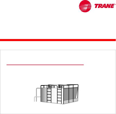
Water chillers are used in a variety of air conditioning and process cooling applications. They cool water that is subsequently transported by pumps and pipes. The water passes through the tubes of coils to cool air in an air
conditioning system, or it can provide cooling for a manufacturing or industrial process. Systems that employ water chillers are commonly called chilledwater systems.
When designing a chilled-water system, one of the first issues that must be addressed is to determine which type of water chiller to use. This period discusses the primary differences in chiller types.
absorption water chiller
centrifugal water chiller
Figure 3
The refrigeration cycle is a key differentiating characteristic between chiller types. The vapor-compression and absorption refrigeration cycles are the two most common cycles used in commercial air conditioning.
TRG-TRC016-EN |
1 |

period one
Types of Water Chillers
notes
Water chillers using the vapor-compression refrigeration cycle vary by the type of compressor used. Reciprocating, scroll, helical-rotary, and centrifugal compressors are common types of compressors used in vapor-compression water chillers.
Absorption water chillers make use of the absorption refrigeration cycle.
Driving Sources
compressor-driven heat-driven
Figure 4
Vapor-compression water chillers use a compressor to move refrigerant around the system. The most common energy source to drive the compressor is an electric motor.
Absorption water chillers use heat to drive the refrigeration cycle. They do not have a mechanical compressor involved in the refrigeration cycle. Steam, hot water, or the burning of oil or natural gas are the most common energy sources for these types of chillers.
2 |
TRG-TRC016-EN |

period one
Types of Water Chillers
notes
Vapor-Compression Cycle
reject heat
D C condenser
compressor
expansion device
|
|
energyin |
A |
evaporator |
B |
|
||
|
absorbheat |
Figure 5 |
|
|
Vapor-Compression Water Chillers
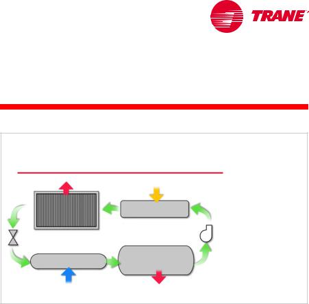
In the vapor-compression refrigeration cycle, refrigerant enters the evaporator in the form of a cool, low-pressure mixture of liquid and vapor (A). Heat is transferred from the relatively-warm air or water to the refrigerant, causing the liquid refrigerant to boil. The resulting vapor (B) is then drawn from the evaporator by the compressor, which increases the pressure and temperature of the refrigerant vapor.
The hot, high-pressure refrigerant vapor (C) leaving the compressor enters the condenser, where heat is transferred to ambient air or water at a lower temperature. Inside the condenser, the refrigerant vapor condenses into a liquid. This liquid refrigerant (D) then flows to the expansion device, which creates a pressure drop that reduces the pressure of the refrigerant to that of the evaporator. At this low pressure, a small portion of the refrigerant boils (or flashes), cooling the remaining liquid refrigerant to the desired evaporator temperature. The cool mixture of liquid and vapor refrigerant (A) travels to the evaporator to repeat the cycle.
The vapor-compression refrigeration cycle is reviewed in detail in the
Refrigeration Cycle Air Conditioning Clinic.
TRG-TRC016-EN |
3 |
period one
Types of Water Chillers
notes
Compressor Types
scroll
reciprocating
helical-rotary |
centrifugal |
Figure 6
The type of compressor used generally has the greatest impact on the efficiency and reliability of a vapor-compression water chiller. The improvement of compressor designs and the development of new compressor technologies have led to more-efficient and -reliable water chillers.
The reciprocating compressor was the workhorse of the small chiller market for many years. It was typically available in capacities up to 100 tons [350 kW]. Multiple compressors were often installed in a single chiller to provide chiller capacities of up to 200 tons [700 kW].
Scroll compressors have emerged as a popular alternative to reciprocating compressors, and are generally available in hermetic configurations in capacities up to 15 tons [53 kW] for use in water chillers. As with reciprocating compressors, multiple scroll compressors are often used in a single chiller to meet larger capacities. In general, scroll compressors are 10 to 15 percent more efficient than reciprocating compressors and have proven to be very reliable, primarily because they have approximately 60 percent fewer moving parts than reciprocating compressors. Reciprocating and scroll compressors are typically used in smaller water chillers, those less than 200 tons [700 kW].
Helical-rotary (or screw) compressors have been used for many years in air compression and low-temperature-refrigeration applications. They are now widely used in medium-sized water chillers, 50 to 500 tons [175 to 1,750 kW]. Like the scroll compressor, helical-rotary compressors have a reliability advantage due to fewer moving parts, as well as better efficiency than reciprocating compressors.
Centrifugal compressors have long been used in larger water chillers. High efficiency, superior reliability, reduced sound levels, and relatively low cost have contributed to the popularity of the centrifugal chiller. Centrifugal compressors are generally available in prefabricated chillers from 100 to 3,000 tons [350 to 10,500 kW], and up to 8,500 tons [30,000 kW] as built-up machines.
4 |
TRG-TRC016-EN |

period one
Types of Water Chillers
notes
These various types of compressors are discussed in detail in the Refrigeration Compressors Air Conditioning Clinic.
Variable-Speed Drives
 variablespeed drive
Figure 7
The capacity of a centrifugal chiller can be modulated using inlet guide vanes (IGV) or a combination of IGV and a variable-speed drive (adjustable-frequency drive, AFD). Variable-speed drives are widely used with fans and pumps, and as a result of the advancement of microprocessor-based controls for chillers, they are now being applied to centrifugal water chillers.
Using an AFD with a centrifugal chiller will degrade the chiller’s full-load efficiency. This can cause an increase in electricity demand or real-time pricing charges. At the time of peak cooling, such charges can be ten (or more) times the non-peak charges. Alternatively, an AFD can offer energy savings by reducing motor speed at low-load conditions, when cooler condenser water
is available. An AFD also controls the inrush current at start-up.
Certain system characteristics favor the application of an adjustable-frequency drive, including:
nA substantial number of part-load operating hours
nThe availability of cooler condenser water
nChilled-water reset control
Chiller savings using condenserand chilled-water-temperature reset, however, should be balanced against the increase in pumping and cooling-tower energy. This is discussed in Period Four. Performing a comprehensive energy analysis is the best method of determining whether an adjustable-frequency drive is desirable. It is important to use actual utility costs, not a “combined” cost, for demand and consumption charges.
Depending on the application, it may make sense to use the additional money that would be needed to purchase an AFD to purchase a more efficient chiller instead. This is especially true if demand charges are significant.
TRG-TRC016-EN |
5 |

period one
Types of Water Chillers
notes
Condenser Types
air-cooled
water-cooled
Figure 8
Air-Cooled or Water-Cooled Condensing
The heat exchangers in the water chiller (the condenser and evaporator) have the second greatest impact on chiller efficiency and cost. One of the most distinctive differences in chiller heat exchangers continues to be the type of condenser selected—air-cooled versus water-cooled.
Air-Cooled or Water-Cooled
water-cooled
air-cooled
0tons |
500tons |
1,000tons |
1,500tons |
2,000tons 2,500tons 3,000tons |
|
[0kW] |
[1,759kW] |
[3,517kW] |
[5,276kW] |
[7,034kW] |
[8,793kW] [10,551kW] |
chiller capacity
Figure 9
When comparing air-cooled and water-cooled chillers, available capacity is the first distinguishing characteristic. Air-cooled chillers are typically available in packaged chillers ranging from 7.5 to 500 tons [25 to 1,580 kW]. Packaged water-cooled chillers are typically available from 10 to 3,000 tons [35 to 10,500 kW].
6 |
TRG-TRC016-EN |
period one
Types of Water Chillers
notes
air-cooled or water-cooled
Maintenance
▲Water treatment
▲Condenser tube brushing
▲Tower maintenance
▲Freeze protection
▲Makeup water
coolingtower
Figure 10
A major advantage of using an air-cooled chiller is the elimination of the cooling tower. This eliminates the concerns and maintenance requirements associated with water treatment, chiller condenser-tube cleaning, tower mechanical maintenance, freeze protection, and the availability and quality of makeup water. This reduced maintenance requirement is particularly attractive to building owners because it can substantially reduce operating costs.
Systems that use an open cooling tower must have a water treatment program. Lack of tower-water treatment results in contaminants such as bacteria and algae. Fouled or corroded tubes can reduce chiller efficiency and lead to premature equipment failure.
TRG-TRC016-EN |
7 |
period one
Types of Water Chillers
notes
air-cooled or water-cooled
Low Ambient Operation
air-cooled chiller
Figure 11
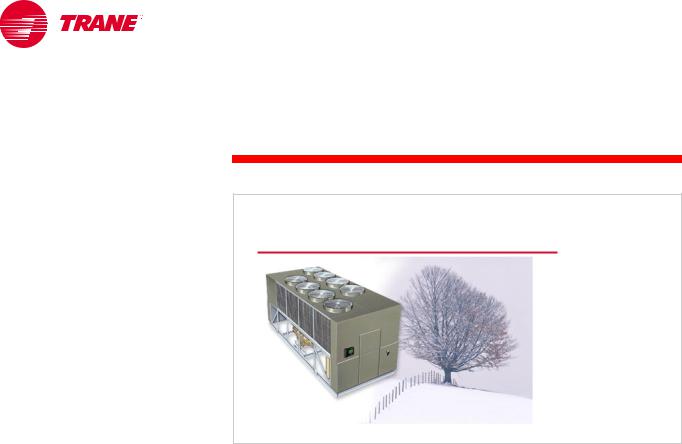
Air-cooled chillers are often selected for use in systems that require year-round cooling requirements that cannot be met with an airside economizer. Air-cooled condensers have the ability to operate in below-freezing weather, and can do so without the problems associated with operating the cooling tower in these conditions. Cooling towers may require special control sequences, basin heaters, or even an indoor sump for safe operation in freezing weather.
For process applications, such as computer centers that require cooling yearround, this ability alone often dictates the use of air-cooled chillers.
8 |
TRG-TRC016-EN |

period one
Types of Water Chillers
notes
air-cooled or water-cooled
Efficiency
temperatureoutdoor |
|
dry bulb |
|
|
|
|
|
|
|
|
|
|
|
|
|
wet bulb |
|
|
||
|
|
|
|
|
||
12 |
12 |
|
|
12 |
||
midnight |
|
noon |
midnight |
|||
Figure 12
Water-cooled chillers are typically more energy efficient than air-cooled chillers. The refrigerant condensing temperature in an air-cooled chiller is dependent on the ambient dry-bulb temperature. The condensing temperature in a water-cooled chiller is dependent on the condenser-water temperature, which is dependent on the ambient wet-bulb temperature. Since the wet-bulb temperature is often significantly lower than the dry-bulb temperature, the refrigerant condensing temperature (and pressure) in a water-cooled chiller can be lower than in an air-cooled chiller. For example, at an outdoor design condition of 95°F [35°C] dry-bulb temperature, 78°F [25.6°C] wet-bulb temperature, a cooling tower delivers 85°F [29.4°C] water to the water-cooled condenser. This results in a refrigerant condensing temperature of approximately 100°F [37.8°C]. At these same outdoor conditions, the refrigerant condensing temperature in an air-cooled condenser is approximately 125°F [51.7°C]. A lower condensing temperature, and therefore a lower condensing pressure, means that the compressor needs to do less work and consumes less energy.
This efficiency advantage may lessen at part-load conditions because the dry-bulb temperature tends to drop faster than the wet-bulb temperature (see Figure 12). As a result, the air-cooled chiller may benefit from greater condenser relief.
Additionally, the efficiency advantage of a water-cooled chiller is much less when the additional cooling tower and condenser pump energy costs are considered. Performing a comprehensive energy analysis is the best method of estimating the operating-cost difference between air-cooled and water-cooled systems.
TRG-TRC016-EN |
9 |

period one
Types of Water Chillers
notes
air-cooled or water-cooled
Comparison
air-cooled |
water-cooled |
||
▲ |
Lower maintenance |
▲ |
Greater energy efficiency |
▲ |
Packaged system |
▲ |
Longer equipment life |
▲ Better low-ambient
operation
Figure 13
Another advantage of an air-cooled chiller is its delivery as a “packaged system.” Reduced design time, simplified installation, higher reliability, and single-source responsibility are all factors that make the factory packaging of the condenser, compressor, and evaporator a major benefit. A water-cooled chiller has the additional requirements of condenser-water piping, pump, cooling tower, and associated controls.
Water-cooled chillers typically last longer than air-cooled chillers. This difference is due to the fact that the air-cooled chiller is installed outdoors, whereas the water-cooled chiller is installed indoors. Also, using water as the condensing fluid allows the water-cooled chiller to operate at lower pressures than the air-cooled chiller. In general, air-cooled chillers last 15 to 20 years, while water-cooled chillers last 20 to 30 years.
To summarize the comparison of air-cooled and water-cooled chillers, air-cooled chiller advantages include lower maintenance costs, a prepackaged system for easier design and installation, and better low-ambient operation. Water-cooled chiller advantages include greater energy efficiency (at least at design conditions) and longer equipment life.
10 |
TRG-TRC016-EN |

period one
Types of Water Chillers
notes
Packaged Air-Cooled Chiller
air-cooled chiller
Figure 14
Packaged or Split Components
Water-cooled chillers are rarely installed with separable components. Air-cooled chillers, however, offer the flexibility of separating the components in different physical locations. This flexibility allows the system design engineer to place the components where they best serve the available space, acoustic, and maintenance requirements of the customer.
A packaged air-cooled chiller has all of the refrigeration components (compressor, condenser, expansion device, and evaporator) located outdoors. A major advantage of this configuration is factory assembly and testing of all chiller components, including the wiring, refrigerant piping, and controls.
This eliminates field labor and often results in faster installation and improved system reliability. Additionally, all noise-generating components (compressors and condenser fans) are located outdoors, easing indoor noise concerns.
Finally, indoor equipment-room space requirements are minimized.
TRG-TRC016-EN |
11 |

period one
Types of Water Chillers
notes
Remote Evaporator Barrel
condensingunit
remote evaporator
refrigerant piping
Figure 15
An alternative to the packaged air-cooled chiller is to use a packaged condensing unit (condenser and compressor) located outdoors, with a remote evaporator barrel located in the indoor equipment room. The two components are connected with field-installed refrigerant piping. This configuration locates the part of the system that is susceptible to freezing (evaporator) indoors and the noise-generating components (compressors and condenser fans) outdoors. This usually eliminates any requirement to protect the chilled-water loop from freezing during cold weather.
This configuration is particularly popular in schools and other institutional applications, primarily due to reduced seasonal maintenance for freeze protection. A drawback of splitting the components is the requirement for field-installed refrigerant piping. The possibility of system contamination and leaks increases when field-installed piping and brazing are required.
Additionally, longer design time is generally required for the proper selection, sizing, and installation of this split system.
12 |
TRG-TRC016-EN |

period one
Types of Water Chillers
notes
Remote Air-Cooled Condenser
air-cooled condenser
refrigerant  piping
condenserless chiller
Figure 16
Another popular configuration is to use an outdoor air-cooled condenser connected to a packaged compressor and evaporator unit (also called a condenserless chiller) that is located in the indoor equipment room. Again, the components are connected with field-installed refrigerant piping.
The primary advantage of this configuration is that the compressors are located indoors, which makes maintenance easier during inclement weather and virtually eliminates the concern of refrigerant migrating to the compressors during cold weather.
TRG-TRC016-EN |
13 |
period one
Types of Water Chillers
notes
Indoor Air-Cooled Condenser
indoor air-cooled condenser
refrigerant piping
condenserless |
|
chiller |
Figure 17 |
|
The final configuration includes a packaged compressor-and-evaporator unit that is located in an indoor equipment room and connected to an indoor, air-cooled condenser. The air used for condensing is ducted from outdoors, through the condenser coil, and rejected either outdoors or inside the building as a means for heat recovery. Indoor condensers typically use a centrifugal fan to overcome the duct static-pressure losses, rather than the propeller fans used in conventional outdoor air-cooled condensers. Again, the components are connected with field-installed refrigerant piping.
This configuration is typically used where an outdoor condenser is architecturally undesirable, where the system is located on a middle floor of a multistory building, or where vandalism to exterior equipment is a problem.
A disadvantage of this configuration is that it typically increases condenser fan energy within compared to a conventional outdoor air-cooled condenser.
Similarly, a packaged cooling tower in a water-cooled system can also be located indoors. This configuration also requires outdoor air to be ducted to and from the cooling tower, and again, typically requires the use of a centrifugal fan. Centrifugal fans use about twice as much energy as a propeller fan, but can overcome the static-pressure losses due to the ductwork. Alternatively, the tower sump can be located indoors, making freeze protection easier.
14 |
TRG-TRC016-EN |
period one
Types of Water Chillers
notes
Absorption Refrigeration Cycle
reject heat
heat energyin
DC
condenser |
generator |
|
expansion |
pump |
|
device |
|
|
evaporator |
absorber |
|
A |
B |
|
|
|
|
absorbheat |
reject heat |
Figure 18 |
Absorption Water Chillers
So far, we have discussed water chillers that use the vapor-compression refrigeration cycle. Absorption water chillers are a proven alternative to vaporcompression chillers. The absorption refrigeration cycle uses heat energy as the primary driving force. The heat may be supplied either in the form of steam or hot water (indirect-fired), or by burning oil or natural gas (direct-fired).
There are two fundamental differences between the absorption refrigeration cycle and the vapor-compression refrigeration cycle. The first is that the compressor is replaced by an absorber, pump, and generator. The second is that, in addition to the refrigerant, the absorption refrigeration cycle uses a secondary fluid called the absorbent. The condenser, expansion device, and evaporator sections, however, are similar.
Warm, high-pressure liquid refrigerant (D) passes through the expansion device and enters the evaporator in the form of a cool, low-pressure mixture of liquid and vapor (A). Heat is transferred from the relatively-warm system water to the refrigerant, causing the liquid refrigerant to boil. Using an analogy of the vapor-compression cycle, the absorber acts like the suction side of the compressor—it draws in the refrigerant vapor (B) to mix with the absorbent. The pump acts like the compression process itself—it pushes the mixture of refrigerant and absorbent up to the high-pressure side of the system. The generator acts like the discharge of the compressor—it delivers the refrigerant vapor (C) to the rest of the system.
The refrigerant vapor (C) leaving the generator enters the condenser, where heat is transferred to cooling-tower water at a lower temperature, causing the refrigerant vapor to condense into a liquid. This high-pressure liquid refrigerant (D) then flows to the expansion device, which creates a pressure drop that reduces the pressure of the refrigerant to that of the evaporator, repeating
the cycle.
The absorption refrigeration cycle is discussed in more detail in the Absorption
Water Chillers Air Conditioning Clinic.
TRG-TRC016-EN |
15 |

period one
Types of Water Chillers
notes
Absorption Chillers Offer Choice
▲Avoid high electric demand charges
▲Minimal electricity needed during emergency situations
▲Waste heat recovery
▲Cogeneration
Figure 19
Absorption water chillers generally have a higher first cost than vaporcompression chillers. The cost difference is due to the additional heat-transfer tubes required in the absorber and generator(s), the solution heat exchangers, and the cost of the absorbent. This initial cost premium is often justified when electric demand charges or real-time electricity prices are a significant portion of the electric utility bill. Because electric demand charges are often highest at the same time as peak cooling requirements, absorption chillers are often selected as peaking or demand-limiting chillers.
Because the absorption chiller uses only a small amount of electricity, backupgenerator capacity requirements may be significantly lower with absorption chillers than with electrically-driven chillers. This makes absorption chillers attractive in applications requiring emergency cooling, assuming the alternate energy source is available.
Some facilities, such as hospitals or factories, may have excess steam or hot water as a result of normal operations. Other processes, such as a gas turbine, generate waste steam or some other waste gas that can be burned. In such applications, this otherwise wasted energy can be used to fuel an
absorption chiller.
Finally, cogeneration systems often use absorption chillers as a part of their total energy approach to supplying electricity in addition to comfort cooling and heating.
16 |
TRG-TRC016-EN |
period one
Types of Water Chillers
notes
Absorption Chiller Types
single-effect |
double-effect |
|
direct-fired
Figure 20
There are three basic types of absorption chillers. They are typically available in capacities ranging from 100 to 1,600 tons [350 to 5,600 kW].
Indirect-fired, single-effect absorption chillers operate on low-pressure steam (approximately 15 psig [205 kPa]) or medium-temperature liquids (approximately 270°F [132°C]), and have a coefficient of performance (COP) of 0.6 to 0.8. In many applications, waste heat from process loads, cogeneration plants, or excess boiler capacity provides the steam to drive a single-effect chiller. In these applications, absorption chillers become conservation devices and are typically base-loaded. This means that they run as the lead chiller to make use of the “free” energy that might otherwise be wasted.
Indirect-fired, double-effect absorption chillers require medium-pressure steam (approximately 115 psig [894 kPa]) or high-temperature liquids (approximately 370°F [188°C]) to operate and, therefore, typically require dedicated boilers. Typical COPs for these chillers are 0.9 to 1.2.
The direct-fired absorption chiller includes an integral burner, rather than relying on an external heat source. Common fuels used to fire the burner are natural gas, fuel oil, or liquid petroleum. Additionally, combination burners are available that can switch from one fuel to another. Typical COPs for direct-fired, double-effect chillers are 0.9 to 1.1 (based on the higher heating value of the fuel). Higher energy efficiency and elimination of the boiler are largely responsible for the increasing interest in direct-fired absorption chillers. These types of absorption chillers have the added capability to produce hot water for heating. Thus, these “chiller–heaters” can be configured to produce both chilled water and hot water simultaneously. In certain applications this flexibility eliminates, or significantly down-sizes, the boilers.
TRG-TRC016-EN |
17 |

period one
Types of Water Chillers
notes
Equipment Rating Standards
Air-Conditioning & Refrigeration Institute (ARI)
Standard 550/590–1998: centrifugal and helical-rotary water chillers
Standard 560–1992: absorption water chillers
Figure 21
Equipment Rating Standards
The Air-Conditioning & Refrigeration Institute (ARI) establishes rating standards for packaged HVAC equipment. ARI also certifies and labels equipment through programs that involve random testing of a manufacturer’s equipment to verify published performance. These equipment rating standards have been developed to aid engineers in comparing similar equipment from different manufacturers. Chiller full-load efficiency is described in terms of kW/ton and coefficient of performance (COP). Additionally, two efficiency values developed by ARI that are receiving increased attention are the Integrated Part-Load Value (IPLV) and Non-Standard Part-Load Value (NPLV).
ARI’s part-load efficiency rating system establishes a single number to estimate both the fulland part-load performance of a stand-alone chiller. As part of ARI Standard 550/590–1998, Water-Chilling Packages Using the Vapor-Compression Refrigeration Cycle, and ARI Standard 560–1992, Absorption Water ChillingHeating Packages, chiller manufacturers may now certify their chiller part-load performance using the IPLV and NPLV methods. This gives the engineering community an easy and certified method to evaluate individual chillers. Understanding the scope and application limits of IPLV and NPLV is, however, crucial to their validity as system performance indicators.
18 |
TRG-TRC016-EN |
period one
Types of Water Chillers
notes
Part-Load Efficiency Rating
Integrated Part-Load Value (IPLV)
Weighted-average load curves
Based on an “average” single-chiller installation
Standard operating conditions
Non-Standard Part-Load Value (NPLV)
Weighted-average load curves
Based on an “average” single-chiller installation
Non-standard operating conditions
Figure 22
The IPLV predicts chiller efficiency at the ARI standard rating conditions, using weighted-average load curves that represent a broad range of geographic locations, building types, and operating-hour scenarios, both with and without an airside economizer. The NPLV uses the same methods to predict chiller efficiency at non-standard rating conditions. Although these weighted-average load curves place greater emphasis on the part-load operation of an average, single-chiller installation, they will not—by definition—represent any particular installation.
Additionally, ARI notes that more than 80 percent of all chillers are installed in multiple-chiller systems. Chillers in these systems exhibit different unloading characteristics than the IPLV weighted formula indicates. Appendix D of Standard 550/590–1998 explains this further:
The IPLV equations and procedure are intended to provide a singlenumber, part-load performance number for water-chilling products. The equation was derived to provide a representation of the average part-load efficiency for a single chiller only. However, it is best to use a comprehensive analysis that reflects the actual weather data, building load characteristics, operational hours, economizer capabilities, and energy drawn by auxiliaries, such as pumps and cooling towers, when calculating the chiller and system efficiency.
Here is the important part:
This becomes increasingly important with multiple-chiller systems because individual chillers operating within multiple-chiller systems are more heavily loaded than single chillers within single-chiller systems.
TRG-TRC016-EN |
19 |

period one
Types of Water Chillers
notes
Standard Rating Conditions
|
evaporator |
condenser |
rating |
|
chiller type |
flow rate |
flow rate |
standard |
|
vapor-compression |
|
|
|
|
• reciprocating |
2.4 gpm/ton |
3.0 gpm/ton |
ARI |
|
• scroll |
550/590–1998 |
|||
• helical-rotary |
[0.043 L/s/kW] |
[0.054 L/s/kW] |
||
• centrifugal |
|
|
|
|
absorption |
2.4 gpm/ton |
3.6 gpm/ton |
|
|
• single-effect |
|
|
||
[0.043 L/s/kW] |
[0.065 L/s/kW] |
|
|
|
|
|
|
||
• double-effect, |
|
4.0 gpm/ton |
ARI |
|
indirect-fired |
2.4 gpm/ton |
[0.072 L/s/kW] |
560–1992 |
|
|
||||
• double-effect, |
[0.043 L/s/kW] |
|
|
|
4.5 gpm/ton |
|
|
||
|
|
|
||
direct-fired |
|
[0.081 L/s/kW] |
|
|
water leaving evaporator = 44°F [6.7°C] |
Figure 23 |
|
water entering condenser = 85°F [29.4°C] |
||
|
The standard rating conditions used for ARI certification represent a particular set of design temperatures and flow rates for which water-cooled and air-cooled systems may be designed. They are not suggestions for good design practice for a given system—they simply define a common rating point to aid comparisons.
In fact, concerns toward improved humidity control and energy efficiency have changed some of the design trends for specific applications. More commonly, chilled-water systems are being designed with lower chilled-water temperatures and lower flow rates. The water flow rate required through the system is decreased by allowing a larger temperature difference through the chiller.
20 |
TRG-TRC016-EN |

period one
Types of Water Chillers
notes
Flow Rates and Temperatures
QBtu/hr = 500 × flow rate × ∆T
[ QW = 4,184 × flow rate × ∆T ]
equation for water only |
Figure 24 |
The temperature difference (∆T) through the chiller and the water flow rate are related. For a given load, as the flow rate is reduced, the ∆T increases, and vice versa.
Q = 500 × flow rate × ∆T
[Q = 4,184 × flow rate × ∆T]
where,
nQ = load, Btu/hr [W]
nflow rate = water flow rate through the chiller, gpm [L/s]
n∆T = temperature difference (leaving minus entering) through the chiller, ºF [°C]
Realize that 500 [4,184] is not a constant! It is the product of density, specific heat, and a conversion factor for time. The properties of water at conditions typically found in an HVAC system result in this value. Other fluids, such as mixtures of water and antifreeze, will cause this factor to change.
Density of water = 8.33 lb/gal [1.0 kg/L]
Specific heat of water = 1.0 Btu/lb°F [4,184 J/kg°K]
8.33 lb/gal × 1.0 Btu/lb° F × 60 min/hr = 500
[1.0 kg/L × 4,184 J/kg° K = 4,184]
TRG-TRC016-EN |
21 |

period one
Types of Water Chillers
notes
Flow Rates and Temperatures
95°F |
44°F |
100°F |
41°F |
|||||||||||
[35°C] |
[6.7°C] |
[37.8°C] |
[5°C] |
|||||||||||
|
|
|
|
|
|
|
|
|
|
|
|
|
|
|
85°F |
|
|
|
|
|
|
|
|
|
|
|
|
|
|
|
|
|
|
|
|
85°F |
|
|
|
|
|
|
|
|
|
|
|
|
|
|
|
|
|
||||||
|
|
|
|
|
|
|
|
|
|
|||||
[29.4°C] |
|
|
|
|
[29.4°C] |
|
|
|
|
|||||
|
|
|
|
|
|
|
||||||||
|
|
|
|
|
|
|
|
|
|
|
|
|
|
|
|
|
54°F |
|
|
|
|
57°F |
|
|
|||||
|
[12.2°C] |
|
|
|
[13.9°C] |
|
|
|||||||
|
|
ARI conditions |
|
low-flow conditions |
||||||||||
|
|
evaporator |
2.4 gpm/ton |
|
|
evaporator |
1.5 gpm/ton |
|||||||
|
|
flow rate |
[0.043 L/s/kW] |
|
|
|
flow rate |
[0.027 L/s/kW] |
||||||
|
|
condenser |
3.0 gpm/ton |
|
|
condenser |
2.0 gpm/ton |
|||||||
|
|
flow rate |
[0.054 L/s/kW] |
|
|
|
flow rate |
[0.036 L/s/kW] |
||||||
Figure 25
In the example system shown in Figure 25, the chilled water is cooled from 57°F [13.9°C] to 41°F [5°C] for a 16°F [8.9°C] ∆T. This reduces the water flow rate required from 2.4 gpm/ton [0.043 L/s/kW] to 1.5 gpm/ton [0.027 L/s/kW].
Reducing water flow rates either: 1) lowers system installed costs by reducing pipe, pump, valve, and cooling tower sizes, or 2) lowers system operating costs by using smaller pumps and smaller cooling tower fans. In some cases, both installed and operating costs can be saved. Low-flow systems will be discussed in more detail in Period Three.
The two ARI rating standards mentioned previously, as well as ASHRAE/IESNA Standard 90.1–1999 (the energy standard), allow reduced chilled-water temperatures and flow rates. System design engineers should examine the use of reduced flow rates to offer value to building owners.
22 |
TRG-TRC016-EN |

period one
Types of Water Chillers
notes
ASHRAE/IESNA Standard 90.1–1999
Energy Standard
Building design and materials
Minimum equipment efficiencies
HVAC system design
Figure 26
ASHRAE/IESNA Standard 90.1–1999, Energy Standard for Buildings, Except Low-Rise Residential Buildings, went into effect in October 1999. ASHRAE is the American Society of Heating, Refrigerating and Air-Conditioning
Engineers and IESNA is the Illuminating Engineering Society of North America. This standard addresses all aspects of buildings except low-rise residential buildings. It contains specific requirements for both water chillers and chilled-water systems.
standard 90.1-1999 efficiency requirements
Electric Vapor-Compression Chillers
chiller type |
capacity |
minimum efficiency* |
|||||
air cooled |
all capacities |
2.8 |
COP |
3.05 |
IPLV |
||
|
|
|
|
|
|
|
|
water-cooled |
|
|
|
|
|
|
|
reciprocating |
all capacities |
4.2 |
COP |
5.05 |
IPLV |
||
|
|
|
|
|
|
||
helical-rotary, scroll |
< 150 tons [528 kW] |
4.45 COP |
5.2 |
IPLV |
|||
|
150 to 300 tons [528 to 1,056 kW] |
4.9 |
COP |
5.6 |
IPLV |
||
|
> 300 tons [1,056 kW] |
5.5 |
COP |
6.15 |
IPLV |
||
|
|
|
|
|
|
|
|
centrifugal |
< 150 tons [528 kW] |
5.0 |
COP |
5.25 |
IPLV |
||
|
150 to 300 tons [528 to 1,056 kW] |
5.55 COP |
5.9 |
IPLV |
|||
|
> 300 tons [1,056 kW] |
6.1 |
COP |
6.4 |
IPLV |
||
* as of October 29, 2001 |
|
|
|
|
|
|
Figure 27 |
|
|
|
|
|
|
|
|
Standard 90.1 contains minimum fulland part-load efficiency requirements for packaged water chillers. The table in Figure 27 is an excerpt from Table 6.2.1C of Addendum J to the standard. It includes the minimum efficiency requirements for electric vapor-compression chillers operating at standard ARI conditions. The standard also contains tables of minimum efficiency requirements for these chillers operating at nonstandard conditions. The test procedure for these chillers is ARI Standard 550/590–1999. Notice that these requirements go into effect on October 29, 2001.
TRG-TRC016-EN |
23 |
 Loading...