


 Loading...
Product Catalog
Indoor Gas Heating Products
Unit Heaters
Duct Furnaces
|
|
|
|
|
|
|
|
|
September 2009 |
|
UH-PRC002-EN |

Introduction
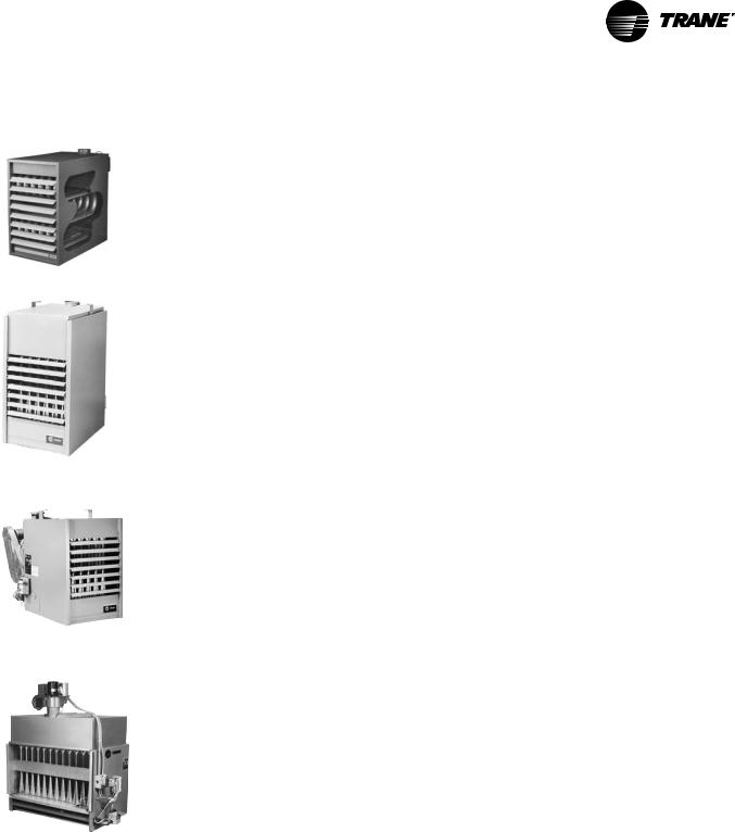
Trane unit heaters, offered in both propeller and centrifugal models, are a complete heat generating and distributing plant, equipped with automatic controls, and packaged in an attractive streamlined housing. Designed for ceiling mounting, they provide a convenient low-cost method of comfortably heating stores, factories, warehouses, and other large open areas.
Trane unit heaters represent a technological breakthrough in quality. Trane offers customers the most complete line of unit heaters anywhere. And every unit in the line has been rated for 80 percent thermal efficiency or better.
But higher thermal efficiency and lower operating costs are just two features of this product line. Innovation—the engineering advances you’ve come to expect from Trane—can also be found across this entire line of unit heaters. And rugged, quality construction provides years of dependable service.
Quality products mean Trane value. So does fair, competitive pricing. The 10-year warranty tells you Trane will be here for the long haul—keeping our commitment to you. You can count on Trane standing behind every unit shipped. That is what Trane value means.
Trademarks
Trane and the Trane logo are trademarks of Trane in the United States and other countries.
© 2009 Trane All rights reserved |
UH-PRC002-EN |

Table of Contents
Introduction . . . . . . . . . . . . . . . . . . . . . . . . . . . . . . . . . . . . . . . . . . . . . . . . . . . . . . . . . . . . 2
Features Highlights . . . . . . . . . . . . . . . . . . . . . . . . . . . . . . . . . . . . . . . . . . . . . . . . . . . . . 4
Features and Benefits . . . . . . . . . . . . . . . . . . . . . . . . . . . . . . . . . . . . . . . . . . . . . . . . . . . 5
Application Considerations . . . . . . . . . . . . . . . . . . . . . . . . . . . . . . . . . . . . . . . . . . . . . . 7
General . . . . . . . . . . . . . . . . . . . . . . . . . . . . . . . . . . . . . . . . . . . . . . . . . . . . . . 7
Venting Unit Heaters . . . . . . . . . . . . . . . . . . . . . . . . . . . . . . . . . . . . . . . . . . 12
Selection Procedure . . . . . . . . . . . . . . . . . . . . . . . . . . . . . . . . . . . . . . . . . . . . . . . . . . . 16
Indoor Gas Heating Units . . . . . . . . . . . . . . . . . . . . . . . . . . . . . . . . . . . . . . . . . . 18
Model Number Descriptions . . . . . . . . . . . . . . . . . . . . . . . . . . . . . . . . . . . . . . . . . . . . 18
Horizontal Blower Assembly . . . . . . . . . . . . . . . . . . . . . . . . . . . . . . . . . . . . . . . 19
General Data . . . . . . . . . . . . . . . . . . . . . . . . . . . . . . . . . . . . . . . . . . . . . . . . . . . . . . . . . . 20
Service Clearances . . . . . . . . . . . . . . . . . . . . . . . . . . . . . . . . . . . . . . . . . . . 20
Heat Throw Data . . . . . . . . . . . . . . . . . . . . . . . . . . . . . . . . . . . . . . . . . . . . . 20
Performance Data . . . . . . . . . . . . . . . . . . . . . . . . . . . . . . . . . . . . . . . . . . . . . . . . . . . . . 24
Controls . . . . . . . . . . . . . . . . . . . . . . . . . . . . . . . . . . . . . . . . . . . . . . . . . . . . . . . . . . . . . . 30
Gas Controls . . . . . . . . . . . . . . . . . . . . . . . . . . . . . . . . . . . . . . . . . . . . . . . . 30
Sequence of Operations . . . . . . . . . . . . . . . . . . . . . . . . . . . . . . . . . . . . . . . . . . . . . . . . 33 Single-Stage Control . . . . . . . . . . . . . . . . . . . . . . . . . . . . . . . . . . . . . . . . . . 33 Two-Stage Control . . . . . . . . . . . . . . . . . . . . . . . . . . . . . . . . . . . . . . . . . . . 34 Electronic Modulating Control (with duct thermostat) . . . . . . . . . . . . . . . 35 Electronic Modulating Control (with room thermostat) . . . . . . . . . . . . . . 37 High-Efficiency Units . . . . . . . . . . . . . . . . . . . . . . . . . . . . . . . . . . . . . . . . . . 39 Separated Combustion Units . . . . . . . . . . . . . . . . . . . . . . . . . . . . . . . . . . . 43
Electrical Data . . . . . . . . . . . . . . . . . . . . . . . . . . . . . . . . . . . . . . . . . . . . . . . . . . . . . . . . . 45
Dimensions and Weights . . . . . . . . . . . . . . . . . . . . . . . . . . . . . . . . . . . . . . . . . . . . . . . 46
Mechanical Specifications . . . . . . . . . . . . . . . . . . . . . . . . . . . . . . . . . . . . . . . . . . . . . . 58 Tubular Heat Exchanger Indoor Gas Unit (model GT) . . . . . . . . . . . . . . . 58 High Efficiency Propeller (model GH) and Centrifugal Fan Gas Unit Heaters
(model GB) . . . . . . . . . . . . . . . . . . . . . . . . . . . . . . . . . . . . . . . . . . . . . . . . . . . . . . . . . . . . 59 Separated Combustion Centrifugal (model GK) and Propeller Fan Gas Unit Heaters (model GA) . . . . . . . . . . . . . . . . . . . . . . . . . . . . . . . . . . . . . . . . . . . . . . . . . . . . . 61 High Efficiency Indoor Gas Duct Furnaces (model GL) . . . . . . . . . . . . . . 63 Separated Combustion Duct Furnaces (model GM) . . . . . . . . . . . . . . . . . 65 Horizontal Blower Assembly (model HBAC) . . . . . . . . . . . . . . . . . . . . . . . 67
UH-PRC002-EN |
3 |

Features Highlights
Ten-Year Warranty
The complete heat exchanger, draft hood assembly of the unit heater and burners are warranted by Trane to be free from defects in material and workmanship for a period of 10 years from the date of manufacture. (Warranty not applicable on duct furnaces or Separated Combustion units.)
Quiet Operation
Trane unit heaters incorporate an exceptionally balanced fan blade to assure quiet operation.
Heat Exchangers
All Trane heat exchangers are available in three types of steel:
•Aluminized Steel (Standard)
•409 Grade Stainless Steel (Optional) (30–400 MBh units)
•321 Grade Stainless Steel (Optional) (100–400 MBh units)
24V System
All units are equipped with a 24Vcontrol system which is powered by a 24V transformer as standard equipment.
Fan Time Delay
The fan time delay switch is mounted at the factory as standard equipment on all unit heaters (optional on duct furnaces). This feature eliminates an initial blast of cold air by allowing the unit to fire for a short period of time before actuating the fan motor. After the thermostat is satisfied (with burners off), the fan continues to operate for approximately one minute, removing residual heat from heat exchanger.
Burners
All sizes 30,000 through 400,000 Btu input are equipped with a proven design pressed steel burner having a unique “burner shade” protective device to prevent scale or foreign matter from plugging the burner ports.
Energy Saving Ignition Pilot Control
The pilot burner is ignited only during each cycle of operation, thereby conserving energy during the off cycle.
LP/Natural Operation
All units are available for operation on either natural or LP gas from our factory.
Easy Access For Maintenance
All Trane unit heaters are so designed that the burner access panel is removed with just two screws. Burners are individually removable for inspection and servicing. Pilot is also accessible through side panel access door.
Test Fire
All Trane unit heaters are test fired to assure proper operation.
Ideal For Retrofit
Trane unit heaters let you pocket fuel savings from day one and provide years of dependable service.
4 |
UH-PRC002-EN |
Features and Benefits
Propeller Fan / Tubular Heat Exchanger Unit Heaters
Trane has added a new unit heater to enhance its broad line of heating products. The Trane tubular heat exchanger is a very durable unit heater that provides an alternative to the traditional clam shell style. These are propeller style units that combine the latest tubular heat exchanger style with inshot burner technology to create a very efficient operating unit.
High Efficiency Propeller Fan Unit Heaters
Trane high-efficiency propeller fan unit heaters achieve annual fuel savings of 20 to 25 percent over conventional gravity vented heaters. Each unit features a factory-installed power venter fan and sealed flue collector that controls combustion and excess air during the on-cycle.
Heated air no longer escapes through the draft diverter opening during the off-cycle. Energy saving spark ignition reduces gas losses. The pilot only operates when required.
Horizontal power venting allows side wall venting, smaller openings, and single-walled vent pipe, reducing heat loss. Higher efficiencies can reduce equipment and material costs as well as installation time.
High Efficiency Centrifugal Fan Unit Heaters
The high-efficiency centrifugal fan unit heater keeps energy costs down. The design advances achieve annual fuel savings of 20 to 25 percent over conventional gravity vented heaters.
The high-efficiency centrifugal unit features integral power venting (factory-installed) and sealed flue collector for optimum combustion. Electronic spark ignition reduces pilot gas losses, and the power venter allows for horizontal venting through side walls. It adds up to higher seasonal efficiencies and lower installation time.
High Efficiency Indoor Duct Furnace
The high efficiency indoor gas duct furnace complements our current centrifugal and propeller fan lines. All high efficiency lines were designed to achieve fuel savings of up to 25 percent over conventional gravity vented heaters.
Conventional gravity vented heaters lost heated room air through the draft diverter opening. The high efficiency line features an integral flue vent fan and sealed flue collector for improved combustion. It reduces air requirements and wind effects on the system’s efficiency. Intermittent pilot ignition reduces pilot gas losses and the flue vent fan allows for horizontal venting through side walls.
Note: DUCT FURNACES ARE APPROVED FOR BLOW-THROUGH APPLICATIONS ONLY.
Horizontal Blower Assemblies
Trane horizontal blower assemblies have been specially designed for air handling systems of high static pressure in combination with Trane duct furnaces. They are matched against the proper furnace size for greatest efficiency of operation.
UH-PRC002-EN |
5 |
Features and Benefits
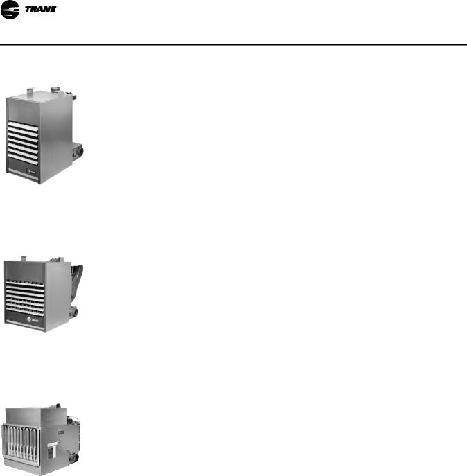
Separated Combustion Propeller Fan Unit Heaters
The Trane separated combustion propeller type unit heater keeps energy costs down by offering 80 percent thermal efficiencies. With model inputs available from 100 through 400 MBH, they are designed to be installed in mildly hostile environments where dusty, dirty and mildly corrosives exist or high humidity or slightly negative pressures prevail.
The Trane propeller unit separates the combustion process from the environment where the unit is installed. A power venting system draws a controlled quantity of combustion air from outside the building. The same system exhausts flue gas products to the outside. The burners, pilot and flue system are enclosed within the unit. The entire combustion process is literally unaffected by the atmosphere in the space where the unit is located.
Combustion and exhaust air may be piped horizontally through a side wall, or vertically through the roof via our standard two-pipe venting arrangement or optional concentric vent kit which utilizes one 8-inch side wall or rooftop penetration for both the combustion and exhaust air. Both venting systems are C.S.A. International certified.
Separated Combustion Centrifugal Fan Unit Heaters
The Trane separated combustion centrifugal type unit heater keeps energy costs down by offering 80 percent thermal efficiencies. With model inputs available from 100 through 400 MBh, they are designed to be installed in mildly hostile environments where dusty, dirty and mildly corrosives exist or high humidity or slightly negative pressures prevail. This unit operates at a static pressure up to 0.2” water column, and is available with a louvered (standard) or flanged outlet (optional) when discharge duct work is desired.
These units separate the combustion process from the environment where the unit is installed. A power venting system draws a controlled quantity of combustion air from outside the building. The same system exhausts flue gas products to the outside. The burners, pilot and flue system are enclosed within the unit. The entire combustion process is literally unaffected by the atmosphere in the space where the unit is located.
Separated Combustion Duct Furnace
The Trane separated combustion duct furnace is designed for installation in dusty, dirty or mildly corrosive environments or where high humidity or slightly negative pressures exist. Ideal applications include HVAC equipment rooms, manufacturing facilities, automotive garages and greenhouses.
6 |
UH-PRC002-EN |
Application Considerations
General
Propeller fan unit heaters and centrifugal fan unit heaters are designed for use in space heating applications. The units are typically used in areas with high ceilings, and are exposed in the space to be heated. Unit heaters offer low installed cost, and are able to heat large volume areas without requiring extensive duct systems.
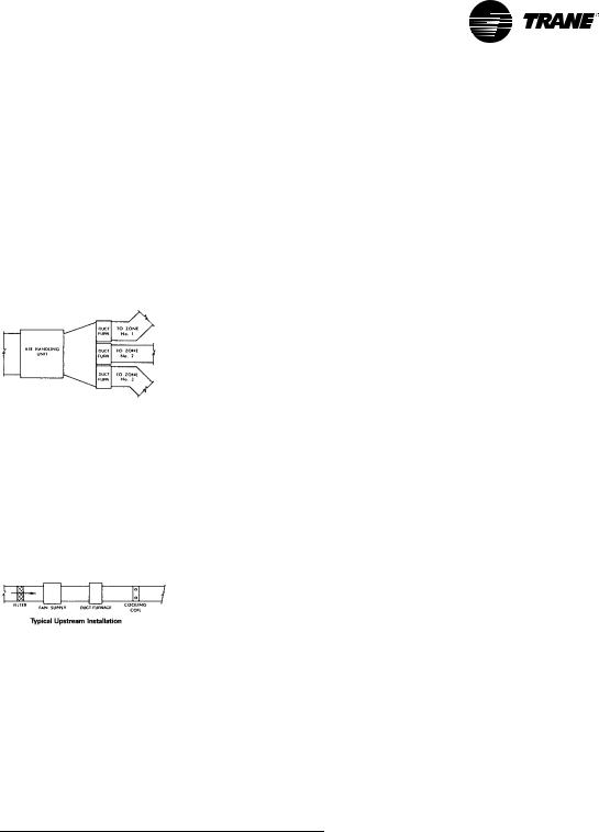
Duct furnaces are designed for use in ducted applications with a separate air handling device such as a horizontal blower assembly. By utilizing a separate air source, greater application flexibility in airflow delivery can be obtained. Multiple duct furnaces can be used with an air handling unit to provide zone heating.
Note: When installing duct furnaces in parallel or in series, minimum clearance requirements must be considered. This is required for serviceability of the gas valve and the high limit. “All duct furnaces are approved in blow-thru applications only.”
All duct furnaces are AGA approved upstream or downstream of the cooling coil. Recommend optional field installed drain pan when installed on the downstream side of the cooling coil.
Note: Downstream denotes cooling coil ahead of the fan section.
When used in conjunction with filters, cooling coils and an air handler, the duct furnace can become part of a built-up heating and cooling system.
Gas Heating Value
The majority of gas heating units are installed in applications where natural gas is readily available. In areas where natural gas is not available, Trane units may be ordered directly from the factory for use on LP (propane) gas.
Gas heat content varies by fuel type and location. The standard gross heating value for natural gas is 1,000 Btu per cubic foot, and for propane, 2,500 Btu per cubic foot. Significant variations from these standard values should be taken into consideration in equipment selections. To account for variations in the gross heating value of the fuel, adjust the total heat input required and select the unit on the basis of the adjusted load using the following formula:
Adjusted load = Calculated load x gross heat value (Btu/ft3)
Actual gross heat value (Btu/ft3)
Low Temperature Rise
Trane recommends against the setup of a unit which will result in a temperature rise of less than 30°F. With such low temperature rises, the flue gases passing through the heat exchanger are cooled to condensate before reaching the flue outlet. This condensate is corrosive and will result in shortened heat exchanger life.
Air Density
Catalog performance data is based on elevations up to 2,000 feet above sea level. Above 2,000 feet the unit’s heating capacity must be derated four percent for each 1,000 feet above sea level, and
UH-PRC002-EN |
7 |

Application Considerations
special orifice selections are required. Table 8, p. 24 contains correction factors that can be applied to the unit’s cataloged heating capacity, fan rpm, and fan bhp to obtain actual values for elevations above 2,000 feet.
Corrosive Atmospheres
Corrosion of heat exchangers and draft diverters have two basic variables—moisture (condensation) and sulphur. These two ingredients form to make sulfuric acid in the combustion process. Condensation occurs commonly in makeup air systems, using large amounts of fresh air, when air temperatures entering the heat exchanger drop to 40°F or below. This reaction can also occur in recirculating systems where some quantity of outside air is introduced upstream of the exchanger. The sulphur will always be present as an integral component of the gas. The resulting concentration of the acid is governed by the amount of sulphur in the gas. This concentration varies from gas to gas and geographically within the same type of gas.
Beyond sulfuric acid corrosion there is the area of chlorinated or halogenated hydrocarbon vapor corrosion. This type of corrosion occurs when substances are mixed with combustion air that will cause the formation of hydrochloric or hydrofluoric acid when burned. These basic substances are found in degreasers, dry cleaning solvents, glues, cements, paint removers and aerosol propellants. Specific chemicals included in this group are trichloroethylene, perchloroethylene, carbon tetrachloride, methylene chloride, methyl chloroform and refrigerants 11, 12, 21, 22 and 114.
If sufficient PPM content of these corrosives is present, none of the common heat exchanger materials will hold up. The dilemma becomes whether to place the gas heating equipment outside of the area to be conditioned, or use equipment in the space which does not burn a fuel such as gas (i.e., electric or hydronic).
Units should not be installed in areas with corrosive or inflammable atmospheres. Locations containing solvents or chlorinated hydrocarbons will produce corrosive acids when coming in contact with burner flames. This reaction will greatly reduce the life of the heat exchanger and may void the warranty. For added protection against heat exchanger corrosion, optional 409 and 321 stainless steel construction is available. On units using outside air, with entering air temperature below 40°F, condensation of flue gas in the heat exchanger is possible. In these cases, stainless steel heat exchangers are recommended.
Careful review of the job application with respect to use, probable contaminants within a conditioned space or the amount of fresh air to be brought in, will help to make the proper selection of heat exchanger material. This review will help to eliminate problems before they begin.
Indoor Units
Indoor gas unit heaters and duct furnaces are used primarily in commercial and industrial structures such as manufacturing areas, warehouses, garages, stores, showrooms, lobbies, and corridors.
Separated combustion units are used primarily in industrial work areas with wood or textile dust, non-explosive contaminated environments, nonchlorine process areas, automotive and truck garages and greenhouses.
Unit Placement
Refer to the applicable Trane Installation, Operation and Maintenance literature for specific installation instructions. Installations must conform with local building codes or in the absence of local codes with the National Fuel Gas Code ANSI Z223.1.
When selecting a location for an indoor unit heater, both the size and weight of the unit, as well as the heating requirements of the building, should be considered. Installation of units in airplane hangars or public garages should be in accordance with NFPA No. 409 for aircraft hangars, and NFPA No. 88 for garages.
For proper distribution, air should be directed towards areas of maximum heat loss. When multiple units are used, circulation of heated air around the space perimeter is recommended. Satisfactory results can also be obtained where multiple units are located toward the center of the area, with
8 |
UH-PRC002-EN |
Application Considerations
heated air being discharged toward the outside walls. Throw data for standard unit heaters and unit heaters utilizing optional discharge nozzles is shown in “General Data,” p. 20.
Locations where extreme drafts can affect burner operation should be avoided. Strong drafts may cause pilot outage. Units with intermittent pilot ignition may be preferable in areas where drafts are likely.
Minimum clearances required for accessibility and safety are listed in Table 2, p. 20.
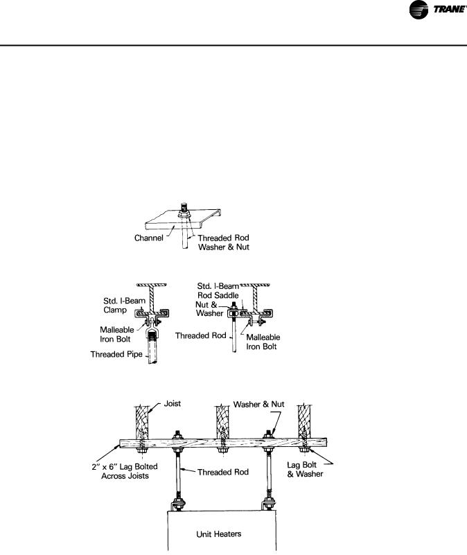
Mounting Detail
(Hanging Hardware Supplied by Others)
Figure 1. Steel Construction
Figure 2. Wood Construction
Throw Data
Throw data for units with standard louvers and for units with optional discharge nozzles are in “General Data,” p. 20. Optional nozzles are for use on propeller fan unit heaters, centrifugal fan unit heaters and duct furnaces. When greater throw distance is desired, a 45° nozzle is recommended. For high mounting heights, a 90° nozzle may be used. When wide diffusion is needed, a Y splitter nozzle should be considered. A five-way nozzle can be used for applications requiring even air
UH-PRC002-EN |
9 |

Application Considerations
distribution over a large floor area. (Five-way nozzles are not available on propeller fan unit heaters.)
Indoor Units—Venting
Gas fired indoor units require venting to remove the products of combustion. To help assure safe, trouble-free operation, follow the guidelines listed below:
Power Vented Units
Units with a factory installed flue vent fan.
1.All units must be vented. Power vented units are designed to use single wallvent pipe. A Breidert Type L, Field Starkap, or equivalent unit vent cap must be furnished by the customer.
2.The venting system for these appliances shall terminate at least 4 feet below, 4 feet horizontally from, or 1 foot above any door, window or gravity air inlet into any building.
3.Through-the-wall vents for these appliances shall not terminate over public walkways or over an area where condensate or vapor could create a nuisance or hazard or could be detrimental to the operation of regulators, relief valves, or other equipment.
4.The vent pipe diameter must be as shown under “Recommended Flue Size” in the specification charts. An adaptor must be field supplied if required.
5.Each furnace must have an individual vent pipe and vent terminal. Vent pipe equivalent length must not exceed 50 feet. Equivalent length is the total length of straight sections, plus 15 feet for each 90° elbow and 8 feet for each 45° elbow.
6.Maintain 6 inch clearance between vent pipe and combustible materials. Vent terminal must be installed with a minimum clearance of 4 feet from electric meters, gas meters, regulators, and relief equipment.
7.Seal vent pipe joints to prevent leakage. Use General Electric RTV-108 or Dow Corning RTV-732 Silicone Sealant or 3M #425 aluminum foil tape.
8.Pitch horizontal pipes downward 1/4-inch per foot toward outlet for condensate drainage. Horizontal portions of the venting system shall be supported at maximum intervals of 4 feet to prevent sagging.
9.Vertical vent pipes should be equipped with condensate drains.
10.Insulate single wall vent pipe exposed to cold air or running through unheated areas.
FM and IRI Requirements
IRI, which stands for Industrial Risk Insurers, and FM, which stands for Factory Mutual, are both basically insurance companies which insure commercial/industrial firms against a variety of losses. Both publish requirements which must be met by certain equipment operating in the facilities they are preparing to insure.
Listed below is our interpretation of the requirements of both insurers pertaining to heating units only to the extent of features/controls required by IRI and/or FM. There are a number of additional requirements which pertain to electrical service, details of installation, etc., and we urge you to obtain copies of the publications pertaining to these details if you are involved in a job where IRI or FM adherence has been indicated. The requirements detailed herein are our interpretations of the latest publications in our possession and we must disclaim any responsibility for errors due to our interpretation and/or lack of any updated revision of these standards. Our intent is to provide you with an understanding of the application of these standards and how we believe our indirectfired gas heating equipment applies.
IRI Requirements
1.All input sizes require 100 percent shutoff. This requires that any natural gas unit, equipped with intermittent pilot ignition, must employ a “lock out” type ignition system which will shut off pilot gas if the pilot fails to light at any time. This system is required by AGA on LP gas units
10 |
UH-PRC002-EN |
Application Considerations
as standard equipment. However, for natural gas units, you need to specify on the order “Natural Gas, 100 percent shutoff.”
2.All units require AGA certification or UL “listed” controls. Our units are AGA certified and meet this requirement.
3.Models with inputs of 150,000 to 400,000 Btu require “mechanical exhaust” and a “safety interlock.” For our units, this means a power vented or drafter-equipped unit. In both instances, if the flue vent fan (factory or field installed) does not get up to speed, the unit will not fire, satisfying the safety interlock portion.
FM Requirements
1.All units must be AGA certified or UL listed. Our units are AGA certified.
2.The high limit control must be in a circuit, the voltage of which does not exceed 120 Vac. All of our high limits would meet this requirement.
The specific requirement for an “IRI or FM Gas Train,” while it applies to direct and indirect-fired gas heating equipment as well as oil-fired, comes into play only with units having an input in excess of 400,000 Btu. This may be one of the reasons why the majority of gas heating equipment manufacturers (indirect-fired) limit their largest individual furnace to 400,000 Btu.
Minimum/Maximum Gas Inlet Pressures
Gas valves are suitable to a maximum inlet pressure of 0.5 psi (14 inches water column) on natural gas. If the main gas supply pressure is greater than 14 inches wc, a step-down pressure regulator must be field-installed ahead of the gas valve. Minimum inlet pressure for natural gas units is
5 inches wc.
For LP (propane) gas, the minimum inlet pressure is 11.0 inches wc and the maximum inlet pressure is 14.0 inches wc.
High Pressure Regulators—Natural Gas Only
The Trane indoor gas heating products contained in this catalog are designed to operate at a pressure of 3.5-inch wc (water column) when firing on natural gas. This is the “manifold” pressure or that which is present at the burner orifices. All fiveand six-function valves provide a built-in pressure regulator which is capable of reducing “supply” pressures from a maximum of 14-inch wc (1/2 psi) down to 3.5-inch wc on the leaving side of the valve. The valve typically “drops” about 1-1/2 inches so the minimum supply pressure is 5-inch wc.
Whenever supply pressures exceed 14 inches wc, a high pressure regulator should be selected. We supply a Rockwell regulator which is fitted with pressure springs and capacity orificing to meet the requirements of each specific job. In order to select the proper spring/orifice combination, we need to know what the supply pressure is on that particular job and the input size of the unit being ordered. More than one unit can be run from one regulator; however, we recommend that each unit have its own regulator.
We require that the “job” supply pressure be included on all jobs requiring high pressure regulators along with the unit size. Table 1 displays the regulators range as it pertains to inlet pressure and MBh. A dash (—) requires the customer to contact a local utility or an industrial supply house.
These devices are not available from Trane for LP gas. LP accessories must be secured from the gas supplier/ supply house.
UH-PRC002-EN |
11 |

Application Considerations
Table 1. Orifice chart: Rockwell 043–182 regulator
Inlet Pressure |
|
Capacity in Mbh for Natural Gas |
|
|
|
||
(psi) |
|
|
|
|
|
|
Spring Required |
25–200 |
225–300 |
350–500 |
600 |
700 |
800 |
||
1 |
3/8” |
— |
— |
— |
— |
— |
Blue (only) |
2 |
3/8” |
3/8” |
— |
— |
— |
— |
Blue (only) |
3 |
3/8” |
3/8” |
3/8” |
— |
— |
— |
Blue or Green |
5 |
3/8” |
3/8” |
3/8” |
3/8” |
3/8” |
3/8” |
Blue or Green |
10 |
3/8” |
3/8” |
3/8” |
3/8” |
3/8” |
3/8” |
Blue or Green |
20 |
1/4” |
1/4” |
1/4” |
1/4” |
1/4” |
5/16” |
Blue or Green |
40 |
1/4” |
1/4” |
1/4” |
1/4” |
1/4” |
1/4” |
Blue or Green |
60 |
1/8” |
1/8” |
1/8” |
1/8” |
1/8” |
3/16” |
Blue or Green |
80 |
1/8” |
1/8” |
1/8” |
1/8” |
1/8” |
— |
Blue or Green |
100 |
1/8” |
1/8” |
1/8” |
1/8” |
1/8” |
1/8” |
Blue or Green |
125 |
1/8” |
1/8” |
1/8” |
1/8” |
1/8” |
1/8” |
Blue or Green |
Venting Unit Heaters
Venting unit heaters and duct furnaces used to be as simple as remembering that warm air rises. With the introduction of new venting equipment and safety controls, things have become a little more technical. Today’s contractor has to know a lot more about proper venting to get the job done within code at a reasonable price.
For starters, ANSI now categorizes vented appliances into four categories. Category I includes noncondensing appliances with negative vent pressure, like the traditional atmospheric unit heater. Category II groups condensing appliances with negative vent pressure.
Category III appliances are non-condensing and operate with a positive vent pressure, like the traditional power vented unit heater. Category IV covers condensing appliances with positive vent pressure.
Venting Categories
|
Non-Condensing |
Condensing |
|
|
|
Negative Vent Pressure |
I |
II |
Positive Vent Pressure |
III |
IV |
Sharing Flues with Other Appliances
Never connect power vented devices to common flues. Mechanically vented appliances must have dedicated vents to the point of termination.
Power Vented Unit Heaters
Mechanically vented appliances have enjoyed increasing acceptance in American facilities. Power vented unit heaters allow installation without the need to penetrate expensive roofing materials. They also offer more flexibility in placement of individual unit heaters.
12 |
UH-PRC002-EN |
Application Considerations
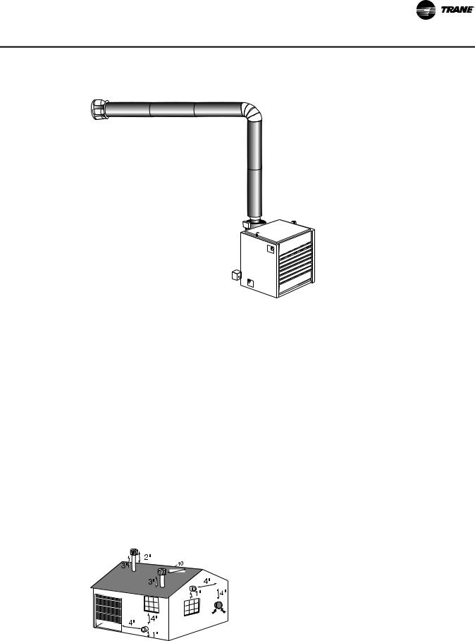
Figure 3. Power vented unit heater
Mechanical venting occurs when a power blower provides a positive air flow to exhaust vent gas. The blower may be mounted at the unit heater or at the point of termination. With a factoryinstalled power venter, a pressure switch detects the flow of vent gas before the gas valve is allowed to open. With third party drafters, a centrifugal switch usually monitors the operation of the blower motor. When properly installed, the switch senses motor rotation and allows the gas valve to operate. Interlocking the blower to the gas valve provides some control over the combustion process. Using a factory unit with a pressure sensitive switch ensures that control.
With all their advantages, power venters bring some requirements as well. Each manufacturer determines the maximum length of pipe and fittings that his system can use for safe operation. Remember to count the fittings and allow for their higher resistance to flow. The total length of run includes not only the piping length, but the resistance of all the fittings including the termination cap.
Many contractors have become accustomed to using B vent with natural draft units. Used with power vented appliances indoors, B vent is unacceptable. B vent does not allow positive pressure in the vent piping to be sealed from the heated space. Proper installation uses 24-gauge, single wall vent pipe and each joint sealed with temperature resistant sealant or tape.
Contractors must also be aware of the conditions at the point of termination. The National Fuel Gas Code NFPA 54/ANSI Z223.1-1992 mandates that vent system should terminate at least 4 feet below, 4 feet horizontally or 1 foot above any window, door, or gravity inlet to a building. Termination with a vent cap approved by the manufacturer should occur well above the snow line.
Figure 4. Vent termination locations (minimum distance)
UH-PRC002-EN |
13 |
Application Considerations
Beyond satisfying the codes, vents should be positioned away from shrubs and plants that might be affected by unseasonable warming by the exhaust. Sidewall vents release a considerable amount of water vapor that may condense on cold siding, adversely affecting painted surfaces. Placing these vents in locations that get natural air circulation from prevailing winds may help to reduce these negative effects.
1 |
1. |
Heat |
|
2. |
Fumes |
||
|
|||
2 |
3. |
Humidity |
|
|
|
3
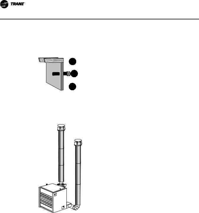
Separated Combustion Venting
Another form of mechanical venting includes those unit heaters that use a powered exhaust also to pull in outside air. Most often found on condensing furnaces, separated combustion does not use room air for combustion. Instead these unit heaters use a second run of pipe to supply fresh outdoor air.
The separated combustion approach offers several advantages. First, it does not use warm indoor air to fire the unit heater. This saves energy by avoiding drawing unheated make-up air into the living space. Second, the unit heater has an unlimited source of air for combustion. In many of the new super insulated buildings appliances can be starved for combustion air. In contaminated atmospheres the use of separated combustion unit heaters assures that the heat exchanger sees only non-corrosive air.
When positioning the intake and exhaust vents on separated combustion equipment, the intake and outlet must mount on the same outside surface. This ensures that any wind effects balance out. Remember to keep the vents at least 18” apart to avoid drawing exhaust air into the intake air.
With Trane’s separated combustion unit heaters intake air and exhaust air run through standard 24-gauge galvanized pipe. Remember that separated combustion unit heaters still have high vent
14 |
UH-PRC002-EN |

Application Considerations
temperatures. Use of PVC, CPVC and other plastic vent materials are inappropriate and hazardous. Check the manufacturer’s instructions before piping any appliance.
The vent gases of power vented and separated combustion unit heaters may condense on a cold start-up or when vent piping runs through unheated areas. To protect the heater always pitch both intake and exhaust piping toward the outside of the building. Remember also that no power vented equipment can share a common flue with any other appliance. Should a flue become blocked one appliance could vent into the occupied space.
Approved vent caps should be used on both the intake and exhaust terminations. For greater convenience Trane offers a concentric vent adapter that allows venting through a single perforation through the building wall or roof.
UH-PRC002-EN |
15 |

Selection Procedure
Determine the total heating load requirements in accordance with methods recommended by the ASHRAE Handbook of Fundamentals or other acceptable means.
High Efficiency Propeller Fan Unit Heater
1.From the performance data tables, select the unit whose heating output meets or exceeds the heating load requirement.
2.Airflow (cfm) and temperature rise can be read directly from the performance data tables.
3.Knowing the mounting height of the unit, throw can be determined from the performance data table. If the throw is not adequate, consider using a larger propeller fan unit heater or a centrifugal fan unit heater with an optional discharge nozzle for greater throw.
Selection Example—A natural gas propeller fan unit heater that can provide 75 MBh heating output is required. The unit will be mounted 10 feet above the floor and a 40-foot throw is required.
Select the unit as follows:
a.From Table 10, p. 25, select a GHND-010 with 100.0 MBh input and 80.0 MBh heating output, 1,480 cfm and a 50°F temperature rise.
b.From Table 3, p. 20, throw at a mounting height of 10 feet is 54 feet.
High Efficiency Centrifugal Fan Unit Heater
1.From the performance data tables, select the unit whose heating output meets or exceeds the heating load requirement.
2.Airflow (cfm) ranges are listed for each unit size in the performance data tables. Knowing either the desired airflow or temperature rise, the other can be calculated using the following formulas:
cfm = |
Output x 1,000 |
|
|
||
1.085 x T |
||
|
||
T = |
Output x 1,000 |
|
|
||
1.085 x cfm |
||
|
3.Knowing the mounting height of the unit, throw can be determined from the performance data table. If the throw is not adequate, a discharge nozzle can be used to obtain additional throw.
Selection Example—An LP (Propane) gas centrifugal fan unit heater that can provide 150 MBh heating output is required. An airflow of 2,000 cfm is desired. The unit will be mounted 12 feet above the floor and a 65-foot throw is required.
Select the unit as follows:
a.From Table 11, p. 25, select a GBPD-020 with a 200.0 MBh input and 160.0 MBh heating output. An airflow of 2,000 cfm is within the allowable range, and temperature rise is calculated as follows:
T = |
MBh x 1,000 |
|
|
|
|
||
1.085 x χφμ |
|
||
|
|
||
T = |
160 x 1,000 |
= 74.0°F |
|
|
|||
1.085 x 2,000 |
|||
|
|
b.From Table 3, p. 20, throw at a 12-foot mounting height is 61 feet. As a 61-foot throw is not adequate, a 60-degree nozzle can be selected (from Table 5, p. 21) which provides a throw of 76 feet.
16 |
UH-PRC002-EN |

Selection Procedure
High Efficiency Duct Furnace
1.From the performance data tables, select the unit whose heating output meets or exceeds the heating load requirement.
2.Given the airflow to be supplied to the duct furnace, temperature rise and pressure drop through the duct furnace can be read directly from the performance data charts. If the air temperature rise is below 30°F, some supply air must be bypassed around the duct furnace. If the air temperature rise is over 80°F, additional supply air must be delivered to the duct furnace.
Selection Example—A natural gas duct furnace that can provide 300 MBh heating output is required. An airflow of 5,000 cfm is being provided to the duct furnace.
Select the unit as follows:
a.From Table 14, p. 27, select a GLND-040 with a 400.0 MBh input and 320.0 MBh heating output.
b.From Figure 10, p. 29, temperature rise at 5,000 cfm is 58°F and pressure drop is 0.16 inches.
Horizontal Blower Assembly
1.From the performance data tables, select the blower assembly that provides the needed airflow at the required static pressure, and determine the required motor size and fan speed.
2.If a blower assembly is to be used with a duct furnace, refer to the dimensional data table to determine which blower to use with the given duct furnace. The duct furnace pressure drop must be added to the pressure drop of the duct system before entering the blower assembly performance data tables. Enter the performance data table at the required airflow and at the total external static pressure to determine the motor size and fan speed.
Selection Example—A GLND-040 high efficiency duct furnace is to be used with a horizontal blower assembly. An airflow of 5,000 cfm is required. The pressure drop of the duct system is 0.54 inches, and the pressure drop of the duct furnace is 0.16 inches.
Select the unit as follows:
a.From Table 29, p. 55, select a HBAC-45 for use with the GLND-040 duct furnace.
b.From Table 16, p. 28, an HBAC-45 at 5,000 cfm and 0.7 inches static pressure (0.54-inch ductwork + 0.16-inch furnace) requires a 1-1/2 hp motor with a fan speed of 720 rpm.
UH-PRC002-EN |
17 |

Model Number Descriptions
Indoor Gas Heating Units
Note: All units are AGA approved. For CGA approved units, contact Air Handling Product Support.
Digit 1 — Gas Heating
Equipment
Digit 2 — Product Type
B |
= |
High Efficiency Centrifugal Fan |
|
|
Unit Heater |
L |
= |
High Efficiency Indoor Duct |
|
|
Furnace |
H= High Efficiency Propeller Fan Unit Heater
A= Separated Combustion Propeller Fan Unit Heater
K= Separated Combustion Centrifugal Fan Unit Heater
M= Separated Combustion Indoor Duct Furnace
T= Propeller Fan / Tubular Heat Exchanger
Digit 3 — Fuel
N |
= |
Natural Gas |
P |
= |
LP Gas (Propane) |
Digit 4 — Development
Sequence
D = Fourth Generation
Digits 5, 6, 7 — Input Capacity
Single Furnace
003(a) = |
30 MBh |
015 |
= |
150 MBh |
|
004(a) = |
45 MBh |
017 |
= |
175 MBh |
|
006(a) = |
60 MBh |
020 |
= |
200 MBh |
|
007(a) = |
75 MBh |
022 |
= |
225 MBh |
|
009 |
= |
90 MBh |
025 |
= |
250 MBh |
010(b) = |
100 MBh |
030 |
= |
300 MBh |
|
011(c) |
= |
105 MBh |
035 |
= |
350 MBh |
120(c) = |
120 MBh |
040 |
= |
400 MBh |
|
012(b) = |
125 MBh |
|
|
|
|
Digit 9 — Gas Control Option
D= Single-Stage, Intermittent Pilot Ignition
E= Two-Stage, Intermittent Pilot
Ignition
H= Electronic Modulating with Room T-Stat, Intermittent Pilot Ignition
J= Electronic Modulating with Duct-Stat, Intermittent Pilot
Ignition
L= Electronic Modulating with External 4–20 mA Input
N= Electronic Modulating with External 0–10 Vdc Input
T |
= |
Single Stage Direct Spark Ignition |
V |
= |
Two-Stage, Direct Spark Ignition |
Digit 10 — Design Sequence
G = Seventh Design
Digit 11 — Heat Exchanger
Material
1= Aluminized Steel
2= #409 Stainless Steel
3= #321 Stainless Steel
Digit 12 — Rooftop
Arrangements
0 = None (Indoor Unit)
Digit 13 — Rooftop Heating Unit
Motor Selection
0= None (Indoor Unit and Rooftop Duct Furnace)
Digit 14 — Rooftop Fan Section
0= None (Indoor Unit and Rooftop Duct Furnace)
(a)Not available for high efficiency propeller fan.
(b)Not available for tubular.
(c)Available for tubular only.
Digit 8 — Main Power Supply
A |
= |
115/60/1 |
D |
= |
230/60/3 |
B |
= |
230/60/1 |
E |
= |
460/60/3 |
C |
= |
208/60/3 |
F |
= |
575/60/3 |
Digit 15 — Miscellaneous
Options
All Units
0 = None
A= #409 Stainless Steel Burners1
B= Orifices For Elevation Above 2000 Feet (Specify Elevation)
Propeller Fan Unit Heater
(High Efficiency and Separated
Combustion)
C= #409 Stainless Steel Draft Diverter
D= Summer-Winter Switch
E= Vertical Louvers
J |
= |
Totally Enclosed Motor |
7 |
= |
OSHA Fan Guard |
Centrifugal Fan Unit Heater
(High Efficiency and Separated
Combustion)
C= #409 Stainless Steel Draft Diverter
D= Summer-Winter Switch
E= Vertical Louvers
H |
= |
Duct Discharge Flange |
J |
= |
Totally Enclosed Motor |
Duct Furnace (Indoor) (High
Efficiency)
C= #409 Stainless Steel Draft Diverter
D= Summer-Winter Switch
F= Horizontal Louvers
G= Horizontal and Vertical Louvers
K= Side Access Burner Drawer (Left Hand)2
L= Fan Time Delay Control
M= Side Access Burner Drawer (Right
Hand)2
Separated Combustion, Indoor Duct
Furnace
C= #409 Stainless Steel Draft Diverter
D= Summer-Winter Switch
F= Horizontal Louvers
G= Horizontal and Vertical Louvers
Propeller Type / Tubular Heat Exchanger
J |
= |
Totally Enclosed Motor |
7 |
= |
OSHA Fan Guard |
1Not available for tubular.
2The left or right hand side of the side access burner drawer, options K & M, is determined by facing the air outlet side of the duct furnace.
18 |
UH-PRC002-EN |

Model Number Descriptions
Horizontal Blower
Assembly
Digit 1, 2, 3 — Horizontal Blower
Assembly
Digit 4 — Development
Sequence
C = Third Generation
Digit 5, 6 — Blower Size
15 = Nominal 1500 cfm
20 = Nominal 2000 cfm
30 = Nominal 3000 cfm
45 = Nominal 4500 cfm
Digit 7 — Transition Size
(Specifies Duct Furnace Size)
0 |
= |
None |
|
|
|
A |
= |
100 MBh |
F |
= |
225 MBh |
B |
= |
125 MBh |
G |
= |
250 MBh |
C |
= |
150 MBh |
H |
= |
300 MBh |
D |
= |
175 MBh |
J |
= |
350 MBh |
E |
= |
200 MBh |
K |
= |
400 MBh |
Digit 8 — Main Power Supply
A |
= |
115/60/1 |
D |
= |
230/60/3 |
B |
= |
230/60/1 |
E |
= |
460/60/3 |
C |
= |
208/60/3 |
|
|
|
Digit 9 — Motor Horsepower
A |
= |
1/3 hp |
D |
= |
1 hp |
B |
= |
1/2 hp |
E |
= |
1-1/2 hp |
C |
= |
3/4 hp |
F |
= |
2 hp |
Digit 10 — Design Sequence
D = Fourth Design
Digit 11 — Miscellaneous
Options
0 |
= |
None |
1 |
= |
Insulation |
3 |
= |
Totally Enclosed Motor |
UH-PRC002-EN |
19 |
General Data
Service Clearances
Table 2. Minimum clearances
|
Duct Furnace |
Propeller & Centrifugal Fan U.H. |
|
|
|
Sides |
18” |
18” |
Top |
6” |
6” |
Bottom |
21”(a) |
21” |
Flue |
6” |
6” |
(a)21” clearance is required for bottom access to burners and pilot. If a side pull-out burner drawer is ordered (duct furnace only), bottom clearance can be reduced to six inches. Side clearance, however, must be increased such that it is adequate for burner drawer removal. Reference Table 27, p. 53.
Heat Throw Data
Figure 5. Standard unit heater applications
Table 3. Standard unit heater—approximate distance of throw at nominal airflow
Distance From |
|
|
|
|
|
|
Unit Size |
|
|
|
|
|
|
|
Floor to Bottom |
|
|
|
|
|
|
Input MBh (kW) |
|
|
|
|
|
|
|
of Unit “H” |
30 |
45 |
60 |
75 |
100 |
125 |
150 |
175 |
200 |
225 |
250 |
300 |
350 |
400 |
ft (m) |
(8.8) |
(13.2) |
(17.6) |
(22.0) |
(29.3) |
(36.6) |
(43.9) |
(51.2) |
(58.6) |
(65.9) |
(73.2) |
(87.8) |
(102.5) |
(117.1) |
8 |
33 |
33 |
33 |
40 |
60 |
65 |
70 |
75 |
80 |
85 |
90 |
105 |
110 |
120 |
(2.4) |
(10.1) |
(10.1) |
(10.1) |
(12.2) |
(18.3) |
(19.8) |
(21.3) |
(22.9) |
(24.4) |
(25.9) |
(27.4) |
(32.0) |
(33.5) |
(36.6) |
10 |
28 |
28 |
28 |
35 |
54 |
56 |
60 |
64 |
68 |
72 |
78 |
90 |
95 |
100 |
(3.0) |
(8.5) |
(8.5) |
(8.5) |
(10.7) |
(16.5) |
(17.1) |
(18.3) |
(19.5) |
(20.7) |
(21.9) |
(23.8) |
(27.4) |
(29.0) |
(30.5) |
12 |
— |
— |
— |
— |
44 |
46 |
49 |
57 |
61 |
65 |
68 |
80 |
84 |
90 |
(3.7) |
|
|
|
|
(13.4) |
(14.0) |
(14.9) |
(17.4) |
(18.6) |
(19.8) |
(20.7) |
(24.4) |
(25.6) |
(27.4) |
15 |
— |
— |
— |
— |
— |
— |
45 |
49 |
52 |
56 |
60 |
70 |
74 |
80 |
(4.6) |
|
|
|
|
|
|
(13.7) |
(14.9) |
(15.8) |
(17.1) |
(18.3) |
(21.3) |
(22.6) |
(24.4) |
20 |
— |
— |
— |
— |
— |
— |
— |
— |
46 |
50 |
54 |
63 |
66 |
70 |
(6.1) |
|
|
|
|
|
|
|
|
(14.0) |
(15.2) |
(16.5) |
(19.2) |
(20.1) |
(21.3) |
20 |
UH-PRC002-EN |
General Data
Figure 6. 30° nozzle
Table 4. 30-degree nozzle—approximate distance of throw at nominal airflow
Distance From Floor |
|
|
|
|
Unit Size |
|
|
|
|
||
|
|
|
|
Input MBh (kW) |
|
|
|
|
|||
to Bottom of Unit “H” |
|
|
|
|
|
|
|
|
|||
100 |
125 |
150 |
175 |
200 |
225 |
250 |
300 |
350 |
400 |
||
ft (m) |
|||||||||||
(29.3) |
(36.6) |
(43.9) |
(51.2) |
(58.6) |
(65.9) |
(73.2) |
(87.8) |
(102.5) |
(117.1) |
||
|
|||||||||||
|
|
|
|
|
|
|
|
|
|
|
|
8 |
65 |
70 |
75 |
80 |
85 |
90 |
95 |
115 |
120 |
125 |
|
(2.4) |
(19.8) |
(21.3) |
(22.9) |
(24.4) |
(25.9) |
(27.4) |
(29.0) |
(35.1) |
(36.6) |
(38.1) |
|
|
|
|
|
|
|
|
|
|
|
|
|
10 |
57 |
60 |
64 |
68 |
72 |
78 |
86 |
99 |
105 |
110 |
|
(3.0) |
(17.4) |
(18.3) |
(19.5) |
(20.7) |
(21.9) |
(23.8) |
(26.2) |
(30.2) |
(32.0) |
(33.5) |
|
12 |
50 |
54 |
57 |
60 |
64 |
70 |
77 |
88 |
94 |
100 |
|
(3.7) |
(15.2) |
(16.5) |
(17.4) |
(18.3) |
(19.5) |
(21.3) |
(23.5) |
(26.8) |
(28.7) |
(30.5) |
|
15 |
— |
45 |
48 |
50 |
53 |
59 |
64 |
74 |
79 |
84 |
|
(4.6) |
|
(13.7) |
(14.6) |
(15.2) |
(16.2) |
(18.0) |
(19.5) |
(22.6) |
(24.1) |
(25.6) |
|
|
|
|
|
|
|
|
|
|
|
|
|
20 |
— |
— |
— |
44 |
47 |
53 |
58 |
66 |
71 |
75 |
|
(6.1) |
|
|
|
(13.4) |
(14.3) |
(16.2) |
(17.7) |
(20.1) |
(21.6) |
(22.9) |
|
Notes:
1.All throw data figures are approximate.
2.— = not recommended at these mounting heights.
3.Nozzles are not available on units below size 100 MBh.
4.Nozzles are available for high-efficiency units. Specify High Efficiency when ordering due to difference in nozzle configuration.
Figure 7. 60° nozzle
Table 5. 60-degree nozzle—approximate distance of throw at nominal airflow
Distance From Floor |
|
|
|
|
Unit Size |
|
|
|
|
||
|
|
|
|
Input MBh (kW) |
|
|
|
|
|||
to Bottom of Unit “H” |
|
|
|
|
|
|
|
|
|||
100 |
125 |
150 |
175 |
200 |
225 |
250 |
300 |
350 |
400 |
||
ft (m) |
|||||||||||
(29.3) |
(36.6) |
(43.9) |
(51.2) |
(58.6) |
(65.9) |
(73.2) |
(87.8) |
(102.5) |
(117.1) |
||
|
|||||||||||
8 |
75 |
80 |
85 |
90 |
95 |
100 |
110 |
125 |
130 |
138 |
|
(2.4) |
(22.9) |
(24.4) |
(25.9) |
(27.4) |
(29.0) |
(30.5) |
(33.5) |
(38.1) |
(39.6) |
(42.1) |
|
10 |
65 |
70 |
75 |
79 |
83 |
88 |
95 |
109 |
115 |
120 |
|
(3.0) |
(19.8) |
(21.3) |
(22.9) |
(24.1) |
(25.3) |
(26.8) |
(29.0) |
(33.2) |
(35.1) |
(36.6) |
|
|
|
|
|
|
|
|
|
|
|
|
|
12 |
60 |
64 |
68 |
72 |
76 |
80 |
84 |
100 |
103 |
108 |
|
(3.7) |
(18.3) |
(19.8) |
(20.7) |
(21.9) |
(23.2) |
(24.4) |
(25.6) |
(30.5) |
(31.4) |
(32.9) |
|
15 |
50 |
54 |
56 |
61 |
65 |
68 |
71 |
85 |
88 |
94 |
|
(4.6) |
(15.2) |
(16.5) |
(17.1) |
(18.6) |
(19.8) |
(20.7) |
(21.6) |
(25.9) |
(26.8) |
(28.7) |
|
20 |
— |
49 |
52 |
55 |
59 |
61 |
65 |
77 |
81 |
85 |
|
(6.1) |
|
(14.9) |
(15.8) |
(16.8) |
(18.0) |
(18.6) |
(19.8) |
(23.5) |
(24.7) |
(25.9) |
|
|
|
|
|
|
|
|
|
|
|
|
|
UH-PRC002-EN |
21 |
Loading...