


 Loading...
Installation, Operation,
and Maintenance
Horizon™ Outdoor Air Unit
Indirect Gas-Fired/Electric Heat
Models: OA1D, OA2D, OA3D
Important: Proper execution of the tasks outlined in this Installation, Operation, and Maintenance manual require and assume the technician has been certified as a start up technician for the Horizon Outdoor Air unit. This includes working knowledge of the Tracer TU program.
 SAFETY WARNING
Only qualified personnel should install and service the equipment. The installation, starting up, and servicing of heating, ventilating, and airconditioning equipment can be hazardous and requires specific knowledge and training. Improperly installed, adjusted or altered equipment by an unqualified person could result in death or serious injury. When working on the equipment, observe all precautions in the literature and on the tags, stickers, and labels that are attached to the equipment.
April 2014 |
OAU-SVX01E-EN |
Introduction
Read this manual thoroughly before operating or servicing this unit.
Warnings, Cautions, and Notices
Safety advisories appear throughout this manual as required. Your personal safety and the proper operation of this machine depend upon the strict observance of these precautions.
The three types of advisories are defined as follows:
 WARNING
 CAUTIONs
NOTICE:
Indicates a potentially hazardous situation which, if not avoided, could result in death or serious injury.
Indicates a potentially hazardous situation which, if not avoided, could result in minor or moderate injury. It could also be used to alert against unsafe practices.
Indicates a situation that could result in equipment or property-damage only accidents.
Important Environmental Concerns
Scientific research has shown that certain man-made chemicals can affect the earth’s naturally occurring stratospheric ozone layer when released to the atmosphere. In particular, several of the identified chemicals that may affect the ozone layer are refrigerants that contain Chlorine, Fluorine and Carbon (CFCs) and those containing Hydrogen, Chlorine, Fluorine and Carbon (HCFCs). Not all refrigerants containing these compounds have the same potential impact to the environment. Trane advocates the responsible handling of all refrigerants-including industry replacements for CFCs such as HCFCs and HFCs.
Important Responsible Refrigerant Practices
Trane believes that responsible refrigerant practices are important to the environment, our customers, and the air conditioning industry. All technicians who handle refrigerants must be certified. The Federal Clean Air Act (Section 608) sets forth the requirements for handling, reclaiming, recovering and recycling of certain refrigerants and the equipment that is used in these service procedures. In addition, some states or municipalities may have additional requirements that must also be adhered to for responsible management of refrigerants. Know the applicable laws and follow them.
 WARNING
Proper Field Wiring and Grounding
Required!
Failure to follow code could result in death or serious injury. All field wiring MUST be performed by qualified personnel. Improperly installed and grounded field wiring poses FIRE and ELECTROCUTION hazards. To avoid these hazards, you MUST follow requirements for field wiring installation and grounding as described in NEC and your local/state electrical codes.
 WARNING
Personal Protective Equipment (PPE)
Required!
Installing/servicing this unit could result in exposure to electrical, mechanical and chemical hazards.
•Before installing/servicing this unit, technicians MUST put on all PPE required for the work being undertaken (Examples; cut resistant gloves/sleeves, butyl gloves, safety glasses, hard hat/bump cap, fall protection, electrical PPE and arc flash clothing). ALWAYS refer to appropriate Material Safety Data Sheets (MSDS)/Safety Data Sheets (SDS) and OSHA guidelines for proper PPE.
•When working with or around hazardous chemicals, ALWAYS refer to the appropriate MSDS/SDS and OSHA/GHS (Global Harmonized System of Classification and Labelling of Chemicals) guidelines for information on allowable personal exposure levels, proper respiratory protection and handling instructions.
•If there is a risk of energized electrical contact, arc, or flash, technicians MUST put on all PPE in accordance with OSHA, NFPA 70E, or other country-specific requirements for arc flash protection, PRIOR to servicing the unit. NEVER PERFORM ANY SWITCHING, DISCONNECTING, OR VOLTAGE TESTING WITHOUT PROPER ELECTRICAL PPE AND ARC FLASH CLOTHING. ENSURE ELECTRICAL METERS AND EQUIPMENT ARE PROPERLY RATED FOR INTENDED VOLTAGE.
Failure to follow instructions could result in death or serious injury.
© 2014 Trane All rights reserved |
OAU-SVX01E-EN |

Introduction
 WARNING
Contains Refrigerant!
System contains oil and refrigerant under high pressure. Recover refrigerant to relieve pressure before opening the system. See unit nameplate for refrigerant type. Do not use non-approved refrigerants, refrigerant substitutes, or refrigerant additives.
Failure to follow proper procedures or the use of nonapproved refrigerants, refrigerant substitutes, or refrigerant additives could result in death or serious injury or equipment damage.
 WARNING
Hazard of Explosion and Deadly Gases!
Never solder, braze or weld on refrigerant lines or any unit components that are above atmospheric pressure or where refrigerant may be present. Always remove refrigerant by following the guidelines established by the EPA Federal Clean Air Act or other state or local codes as appropriate. After refrigerant removal, use dry nitrogen to bring system back to atmospheric pressure before opening system for repairs. Mixtures of refrigerants and air under pressure may become combustible in the presence of an ignition source leading to an explosion. Excessive heat from soldering, brazing or welding with refrigerant vapors present can form highly toxic gases and extremely corrosive acids. Failure to follow all proper safe refrigerant handling practices could result in death or serious injury.
Copyright
This document and the information in it are the property of Trane, and may not be used or reproduced in whole or in part without written permission. Trane reserves the right to revise this publication at any time, and to make changes to its content without obligation to notify any person of such revision or change.
Trademarks
All trademarks referenced in this document are the trademarks of their respective owners.
Revision History
OAU-SVX01E-EN (17 Apr 2014)
•Model number updates
OAU-SVX01E-EN |
3 |

Table of Contents |
|
Introduction . . . . . . . . . . . . . . . . . . . . . . . . . . |
. . . 2 |
Warnings, Cautions, and Notices . . . . . |
. . . 2 |
Important Environmental Concerns . . . . . 2 |
|
Important Responsible Refrigerant Practices |
|
. . . . . . . . . . . . . . . . . . . . . . . . . . . . . . . . |
. . . 2 |
Model Number Descriptions . . . . . . . . . . . |
. . . 6 |
Horizon Outdoor Air Unit . . . . . . . . . . . . |
. . . 6 |
General Information . . . . . . . . . . . . . . . . . . |
. . . 9 |
Overview of Manual . . . . . . . . . . . . . . . |
. . . 9 |
Model Number Description . . . . . . . . . |
. . . 9 |
Unit Nameplate . . . . . . . . . . . . . . . . . . |
. . . 9 |
Compressor Nameplate . . . . . . . . . . . . . |
. . 9 |
Unit Description . . . . . . . . . . . . . . . . . . . |
. . 9 |
Indoor Fan Failure Input . . . . . . . . . . . . |
. . 9 |
Low Pressure Control ReliaTel Control |
. . 9 |
Refrigerant Circuits . . . . . . . . . . . . . . . . |
. . 9 |
High Pressure Control ReliaTel Control |
. . 9 |
Space Temperature / RH Sensor (Optional) |
|
. . . . . . . . . . . . . . . . . . . . . . . . . . . . . . . . . |
. 10 |
High Temperature Sensor . . . . . . . . . . . |
. 10 |
Outdoor Air Temperature and Relative Hu- |
|
midity Sensor . . . . . . . . . . . . . . . . . . . . . |
. 10 |
Control Input (Occupied / Unoccupied) |
. 10 |
Hot Gas Reheat . . . . . . . . . . . . . . . . . . . . |
. 10 |
100 Percent Outdoor Air Hood with Damper |
|
and Filters . . . . . . . . . . . . . . . . . . . . . . . . |
. 10 |
Modulating Indirect Gas-Fired Burner |
. . 10 |
Through the Base Electrical with Disconnect |
|
Switch . . . . . . . . . . . . . . . . . . . . . . . . . . . |
. 10 |
Through the Base Gas Piping . . . . . . . . |
. 10 |
Hinged Access Doors . . . . . . . . . . . . . . . |
. 10 |
Modulating Electric Heat . . . . . . . . . . . . |
. 10 |
Unit Inspection . . . . . . . . . . . . . . . . . . . . . . |
. 11 |
First Aid Measures . . . . . . . . . . . . . . . . . |
. 11 |
Storage . . . . . . . . . . . . . . . . . . . . . . . . . . |
. 11 |
Unit Clearances . . . . . . . . . . . . . . . . . . . |
. 11 |
Unit Clearances, Curb Dimensions, and Dimen- |
|
sional Data . . . . . . . . . . . . . . . . . . . . . . . . . . . . |
. 12 |
OA1 Units . . . . . . . . . . . . . . . . . . . . . . . . . . |
. 12 |
Unit Clearances . . . . . . . . . . . . . . . . . . . |
. 12 |
Curb Dimensions . . . . . . . . . . . . . . . . . . . .12
Dimensional Data . . . . . . . . . . . . . . . . . . . .13
OA2 Units . . . . . . . . . . . . . . . . . . . . . . . . . . . .14
Unit Clearances . . . . . . . . . . . . . . . . . . . . .14
Curb Dimensions . . . . . . . . . . . . . . . . . . . .15
Dimensional Data . . . . . . . . . . . . . . . . . . . .15
OA3 Units . . . . . . . . . . . . . . . . . . . . . . . . . . . .16
Unit Clearances . . . . . . . . . . . . . . . . . . . . .16
Curb Dimensions . . . . . . . . . . . . . . . . . . . .17
Dimensional Data . . . . . . . . . . . . . . . . . . . .17
Unit Weight and Rigging . . . . . . . . . . . . . . . . .18
Unit Weight . . . . . . . . . . . . . . . . . . . . . . . . .18
Corner Weight . . . . . . . . . . . . . . . . . . . . . .19
Rigging . . . . . . . . . . . . . . . . . . . . . . . . . . . .20
. . . . . . . . . . . . . . . . . . .21
Space Control with Indirect Gas-Fired or Electric Heat and Modulating HGRH, ERV, and Powered Ex. . . . . . . . . . . . . . . . . . . . . . . . . . .21
Sequence of Operation—”Occupied” . . .21
Sequence of Operation—”Unoccupied” .22
Discharge Air Control with Indirect Gas-Fired or Electric Heat and Modulating HGRH, ERV, and Powered Ex. . . . . . . . . . . . . . . . . . . . . . .23
Sequence of Operation—”Occupied” . . .23
Sequence of Operation—”Unoccupied” .24
Installation . . . . . . . . . . . . . . . . . . . . . . . . . . . . . .25
Ductwork . . . . . . . . . . . . . . . . . . . . . . . . . . .25
General Unit Requirements . . . . . . . . . . . .25
Main Electrical Power Requirements . . . .26
Condensate Drain Configuration . . . . . . .26
Filter Installation . . . . . . . . . . . . . . . . . . . . .26
Field Installed Power Wiring . . . . . . . . . . .26
Main Unit Power . . . . . . . . . . . . . . . . . . . . . .28
Standard Wiring . . . . . . . . . . . . . . . . . . . . .28
Voltage Imbalance . . . . . . . . . . . . . . . . . . .28
Electrical Phasing (Three-Phase Motors) .29
Compressor Crankcase Heaters . . . . . . . .29
Main Unit Display and ReliaTel Controls .30
Field-Installed Control Wiring . . . . . . . . . .30
Control Power Transformer . . . . . . . . . . .30
4 |
OAU-SVX01E-EN |

Controls Using 24 Vac . . . . . . . . . . . . . . . 30
Controls Using DC Analog Input/Output
(Standard Low Voltage Multiconductor Wire)
. . . . . . . . . . . . . . . . . . . . . . . . . . . . . . . . . . 31
DC Conductors . . . . . . . . . . . . . . . . . . . . . . . 31
System Configuration and Pre-Start . . . . . . 33
Start-Up . . . . . . . . . . . . . . . . . . . . . . . . . . . . . . . 36
Indirect Gas-Fired Heating Start-Up . . . . . 36
Start-Up Procedure . . . . . . . . . . . . . . . . . 36
Safety Controls . . . . . . . . . . . . . . . . . . . . . 39
Maintenance . . . . . . . . . . . . . . . . . . . . . . . . . . . 40
Monthly Maintenance . . . . . . . . . . . . . . . . . 40
Filters . . . . . . . . . . . . . . . . . . . . . . . . . . . . . 40
Supply/Return Air Smoke Detector Maintenance . . . . . . . . . . . . . . . . . . . . . . . . . . . . . 40
Cooling Season . . . . . . . . . . . . . . . . . . . . 40
Heating Season . . . . . . . . . . . . . . . . . . . . 40
Condenser Coil Cleaning . . . . . . . . . . . . . 40
Final Process . . . . . . . . . . . . . . . . . . . . . . . . . 41
Performance Data . . . . . . . . . . . . . . . . . . . . . . 42
Superheat and Refrigeration Circuit Data 48
Alarms and Troubleshooting . . . . . . . . . . . . 52
Microprocessor Control . . . . . . . . . . . . . . 52
System Alarms . . . . . . . . . . . . . . . . . . . . . 52
Sensor Failure Alarm Display . . . . . . . . . 52
RTRM Failure Modes . . . . . . . . . . . . . . . . 54
Appendix . . . . . . . . . . . . . . . . . . . . . . . . . . . . . . 55
OAU Filter Guide . . . . . . . . . . . . . . . . . . . . . 55
OAU-SVX01E-EN |
5 |

Model Number Descriptions
O A 2 D 3 0 0 A 4 - D 1 A 1 A 0 G M - G 1 K B 0 A C 3 C J - A 4 1 B 1 0 2 A 0
1 2 3 4 5 6 7 8 9 10 11 12 13 14 15 16 17 18 19 20 21 22 23 24 25 26 27 28 29 30 31 32 33 34 35 36 37 38 39
Horizon Outdoor Air
Unit
Digit 1, 2 — Unit Type
OA = Outdoor Air
Digit 3 — Cabinet Size
1= 625 cfm–4,000 cfm
2= 1,500 cfm–9,000 cfm
3= 3,750 cfm–13,500 cfm
Digit 4 — Major Design
Sequence
C= Revision 4
D= Revision 5
E= Heat Pump
Digit 5, 6, 7 — Normal Gross Cooling Capacity (MBh)
000= No Cooling
060 = 5 Tons High Efficiency
072 = 6 Tons High Efficiency
084 = 7 Tons High Efficiency
096 = 8 Tons High Efficiency
120 = 10 Tons High Efficiency
144 = 12 Tons High Efficiency
180 = 15 Tons High Efficiency
210 = 17 Tons High Efficiency
240 = 20 Tons High Efficiency
264 = 22 Tons High Efficiency
300 = 25 Tons High Efficiency
360 = 30 Tons High Efficiency
420 = 35 Tons High Efficiency
480 = 40 Tons High Efficiency
540 = 45 Tons High Efficiency
600 = 50 Tons High Efficiency
648 = 54 Tons High Efficiency
Digit 8 — Minor Design
Sequence
A
B
Digit 9 — Voltage Selection
1 |
= |
115/60/1 |
2 |
= |
208-230/60/1 |
3 |
= |
208-230/60/3 |
4 |
= |
460/60/3 |
5 |
= |
575/60/3 |
Digit 10 — Reserved for Future Use
Digit 11 — Evaporator Type
0 = No Cooling
A= DX 3-Row
B= DX 4-Row
C= DX 4-Row Interlaced
D= DX 6-Row Interlaced
E= DX 8-Row
F= Glycol/Chilled Water Coil
G= DX 4-Row with
MSP® Technology
Digit 12 — Hot Gas Reheat
0= No HGRH
1= Fin and Tube Modulating
2= Fin and Tube On/Off
3= Microchannel Modulating
4= Microchannel On/Off
Digit 13 — Compressor
0 = No Compressors
A= Scroll Compressors
B= Digital Scroll (1st Circuit Only)
C= Digital Scroll (1st and 2nd Circuit)
D= Variable Speed Scroll (1st Circuit Only)
E= Variable Speed Scroll (1st and
2nd Circuit)
Digit 14 — Condenser
0= No Condenser
1= Air-Cooled Fin and Tube
2= Air-Cooled Fin and Tube w/Head Pressure On/Off Control
3= Water-Cooled DX Condenser Copper/Steel
4= Air-Cooled Fin and Tube
w/Head Pressure Variable Speed
5= Air-Cooled Microchannel
6= Air-Cooled Microchannel w/Head Pressure On/Off Control
7= Air-Cooled Microchannel Variable Speed
8= Water-Cooled DX Condenser Copper/Nickel
Digit 15 — Refrigerant Capacity
Control
0 = No RCC Valve
A= RCC Valve on 1st Circuit
B= RCC Valve on 1st and 2nd Circuit
C= ERCC Valve on 1st Circuit
D= ERCC Valve on 1st and 2nd Circuit
E= HGBP Valve on 1st Circuit
F= HGBP Valve on 1st and
2nd Circuit
Digit 16 — Indoor Fan Motor (IFM)
0= Direct Drive w/VFD
1= Direct Drive (VFD by Others)
2= Belt Drive
3= Belt Drive w/VFD
4= Direct Drive w/Shaft Grounding Ring w/VFD
5= Special Motor Option
Digit 17 — Indoor Fan Wheel
A |
= |
122 |
B |
= |
122.6 |
C |
= |
150 |
D |
= |
150.6 |
E |
= |
165 |
F |
= |
165.6 |
G |
= |
182 |
H |
= |
182.6 |
J |
= |
200 |
K |
= |
200.6 |
L= 182 X 2
M= 182.6 X 2
Digit 18 — Indoor Fan Motor
Power (hp)
A= 1/2 hp—1800 rpm
B= 1/2 hp—3600 rpm
C= 3/4 hp—1800 rpm
D= 3/4 hp—3600 rpm
E= 1 hp—1800 rpm
F= 1 hp—3600 rpm
G= 1.5 hp—1800 rpm
H= 1.5 hp—3600 rpm
J= 2 hp—1800 rpm
K= 2 hp—3600 rpm
L= 3 hp—1800 rpm
M= 3 hp—3600 rpm
N= 5 hp—1800 rpm
P = 5 hp—3600 rpm
R= 7.5 hp—1800 rpm
S= 7.5 hp—3600 rpm
T= 10 hp—1800 rpm
U= 10 hp—3600 rpm
V= 15 hp—1800 rpm
W= 15 hp—3600 rpm
Digit 19 — Reserved for Future Use
Digit 20 — Heat Type (PRI/SEC)
0 = No Heat
A= Indirect-Fired (IF)
B= Direct-Fired (DF)
C = Electric—4-Stage
D= Electric—SCR Modulating
E= Dual Fuel (PRI-IF/SEC-DF)
F= Dual Fuel (PRI-ELEC/SEC-DF)
G= Dual Fuel (PRI-IF/SEC-ELEC)
H= Dual Fuel (PRI-ELEC/SEC-ELEC)
J= Hot Water
K= Steam
Digit 21 — Primary Fuel Type
0= No Heat
1= Natural Gas
2 = Propane
3= Electric—Open Coil
4= Electric—Sheathed Coil
5= Hot Water
6= Steam
6 |
OAU-SVX01E-EN |

Model Number Descriptions
Digit 22 — Heat Capacity
(Primary Heat Source)
Digit |
IF |
ELEC |
0 |
No Heat |
No Heat |
A |
50 MBh |
10 kW |
B |
75 MBh |
20 kW |
C |
100 MBh |
24 kW |
D |
125 MBh |
28 kW |
E |
150 MBh |
32 kW |
F |
200 MBh |
40 kW |
G |
250 MBh |
48 kW |
H |
300 MBh |
60 kW |
J |
350 MBh |
68 kW |
K |
400 MBh |
79 kW |
L |
500 MBh |
99 kW |
M |
600 MBh |
111 kW |
N |
700 MBh |
119 kW |
P |
800 MBh |
139 kW |
R |
1000 MBh |
159 kW |
S179 kW
T199 kW
U215 kW
XSpecial Heater Option
Digit 23 — Heat Capacity
(Secondary Heat Source)
Digit |
IF |
ELEC |
DF |
0 |
No Heat/No Secondary Heat |
||
A |
50 MBh |
10 kW |
300 MBh |
B |
75 MBh |
20 kW |
600 MBh |
C |
100 MBh |
24 kW |
900 MBh |
D |
125 MBh |
28 kW |
1200 MBh |
E |
150 MBh |
32 kW |
|
F |
200 MBh |
40 kW |
|
G |
250 MBh |
48 kW |
|
H |
300 MBh |
60 kW |
|
J |
350 MBh |
68 kW |
|
K |
400 MBh |
79 kW |
|
L |
500 MBh |
99 kW |
|
M |
600 MBh |
111 kW |
|
N |
700 MBh |
119 kW |
|
P |
800 MBh |
139 kW |
|
R |
1000 MBh |
159 kW |
|
S179 kW
T199 kW
U215 kW
Digit 24 — Corrosive
Environment Package
0= No Corrosive Package
1= S/S Cabinet, Basepan, Eco-Coated Coils
2= S/S Cabinet, Basepan
3= S/S Basepan, Eco-Coated Coils
4= S/S Coil Casing
5= S/S Interior Casing
6= Eco-Coated Coils
7= S/S Coil Casing with
Eco-Coated Coils
8= Copper/Copper Condenser, Evap, HGRH Coils
Digit 25, 26 — Unit Controls
00 = Non-DDC—Electromechanical
AA= Trane—Discharge Air Control w/LON Read-Write w/Display
AB = Trane—Space Control w/LON Read-Write w/Display
AC = Trane—Discharge Air Control w/BACnet® (No Display)
AD = Trane—Space Control w/BACnet (No Display)
AF = Trane—Discharge Air Control w/BACnet w/Display
AG = Trane—Space Control w/BACnet w/Display
AH = Trane—Discharge Air Control w/BACnet w/Display
AI = Trane—Discharge Air Control w/LON Read-Write (No Display)
AJ = Trane—Space Control
w/LON Read-Write (No Display) AK = Trane—Multi-Zone VAV Control
w/LON Read-Write w/Display AL = Trane—Multi-Zone VAV Control
w/BACnet w/Display
AM = Trane—Multi-Zone VAV Control w/LON Read-Write (No Display)
AN = Trane—Multi-Zone VAV Control w/BACnet (No Display)
AO = Trane—Single-Zone VAV Control w/LON Read-Write w/Display
AP = Trane—Single-Zone VAV Control w/BACnet w/Display
AQ = Trane—Single-Zone VAV Control w/LON Read-Write (No Display)
AR = Trane—Single-Zone VAV Control w/BACnet (No Display)
Digit 27 — Powered Exhaust Fan
Motor (PFM) and Exhaust
Dampers
0= No Powered Exhaust
1= Direct Drive w/VFD and Gravity Dampers
2= Direct Drive (VFD by Others)
3= Belt Drive
4= Belt Drive w/VFD
5= Special Motor Option
6= Direct Drive w/VFD and Barometric Relief Damper
7= Direct Drive w/VFD and Isolation Dampers w/End Switch
8= Barometric Relief Dampers
(NO PFM)
Digit 28 — Powered Exhaust Fan
Wheel
0 |
= |
No Powered Exhaust |
A |
= |
122 |
B |
= |
122.6 |
C |
= |
150 |
D |
= |
150.6 |
E |
= |
165 |
F |
= |
165.6 |
G |
= |
182 |
H |
= |
182.6 |
J |
= |
200 |
K |
= |
200.6 |
L= 182 X 2
M= 182.6 X 2
Digit 29 — Powered Exhaust Fan
Motor Power
0 = No Powered Exhaust
A= 1/2 hp—1800 rpm
B= 1/2 hp—3600 rpm
C= 3/4 hp—1800 rpm
D= 3/4 hp—3600 rpm
E= 1 hp—1800 rpm
F= 1 hp—3600 rpm
G= 1.5 hp—1800 rpm
H= 1.5 hp—3600 rpm
J= 2 hp—1800 rpm
K= 2 hp—3600 rpm
L= 3 hp—1800 rpm
M= 3 hp—3600 rpm
N= 5 hp—1800 rpm
P = 5 hp—3600 rpm
R= 7.5 hp—1800 rpm
S= 7.5 hp—3600 rpm
T= 10 hp—1800 rpm
U= 10 hp—3600 rpm
V= 15 hp—1800 rpm
W= 15 hp—3600 rpm
Digit 30 — Reserved for Future Use
Digit 31 — ERV (Requires
Powered Exhaust)
0 = No ERV
A= ERV-Composite Construction
B= ERV—Composite Construction with Frost Protection w/VFD
C= ERV—Composite Construction with Bypass
D= ERV—Composite Construction with Frost Protection and Bypass
E= ERV—Aluminum Construction
F= ERV—Aluminum Construction with Frost Protection w/VFD
G= ERV—Aluminum Construction with Bypass
H= ERV—Aluminum Construction with Frost Protection and Bypass
Digit 32 — ERV Size
0 |
= |
No ERV |
1 |
= |
3014 |
2 |
= |
3622 |
3 |
= |
4136 |
4 |
= |
4634 |
5 |
= |
5856 |
6 |
= |
6488 |
7 |
= |
6876 |
8 |
= |
74122 |
Digit 33 — Damper Options
0= 100% OA 2-Position Damper
1= 100% OA 2-Position Damper w/RA 2-Position Damper
2= Modulating OA and RA Dampers w/Economizer
OAU-SVX01E-EN |
7 |

Model Number Descriptions
Digit 34 — Filtration Options
A= Aluminum Mesh Intake Filters (ALM)
B= MERV-8,30%, and ALM
C= MERV-13, 80%, and ALM
D= MERV-14, 95%, and ALM
E= MERV-8 30%, MERV-13 80%, and ALM
F= MERV-8 30%, MERV-14 95%, and ALM
G= MERV-8, 30%, and ALM, with UVC
H= MERV-13, 80%, and ALM, with
UVC
J= MERV-14, 95%, and ALM, with UVC
K= MERV-8 30%, MERV-13 80%, ALM, and UVC
L= MERV-8 30%, MERV-14 95%, ALM, and UVC
M= MERV-8 30%, ALM, and TCACS
N= MERV-13 80%, ALM, and TCACS
P= MERV-14 95%, ALM, and TCACS
Q= MERV-8 30%, MERV-13 80%, ALM, and TCACS
R= MERV-8 30%, MERV-14 95%, ALM, and TCACS
X = Special Filter Options
Digit 35 — Smoke Detector (Factory-Installed)
0= No Smoke Detector
1= Supply Smoke Detector
2= Return Smoke Detector
3= Supply and Return Smoke Detector
Digit 36 — Electrical Options
0 = Non-Fused Disconnect
A= Fused Disconnect Switch
B= Non-Fused Disconnect w/Convenience Outlet
C= Fused Disconnect Switch w/Convenience Outlet
D= Dual Point Power w/Convenience Outlet
F= 65 SCCR Electrical Rating w/Non-Fused Disconnect
G= 65 SCCR Electrical Rating w/Fused Disconnect
H= 65 KAIC Electrical Rating w/Non-Fused Disconnect
J= 65 KAIC Electrical Rating w/Fused Disconnect
Digit 37 — Air Flow Monitoring
0= No Airflow Monitoring
1= Airflow Monitoring—IFM Piezo Ring
2= Airflow Monitoring—PE Piezo Ring
3= Airflow Monitoring—Outdoor Air with Display and IFM
w/Piezo Ring
4= Airflow Monitoring—IFM
Piezo Ring and PE Piezo Ring
5= Airflow Monitoring—Outdoor Air Monitoring w/Display Supply Air and Exhaust Air
w/Piezo Rings
Digit 38 — Accessories
0 |
= |
No Options |
A |
= |
Hailguards |
B= LED Service Light and
C= Hailguards and LED Service Light
Digit 39 — Altitude
0= Sea Level to 1,000 Feet
1= 1,001 to 2,000 Feet
2= 2,001 to 3,000 Feet
3= 3,001 to 4,000 Feet
4= 4,001 to 5,000 Feet
5= 5,001 to 6,000 Feet
6= 6,001 to 7,000 Feet
7= Above 7,000 Feet
8 |
OAU-SVX01E-EN |

General Information
Overview of Manual
Note: One copy of this document ships inside the control panel of each unit and is customer property. It must be retained by the unit’s maintenance personnel.
This booklet describes proper installation, operation, and maintenance procedures for air cooled systems. By carefully reviewing the information within this manual and following the instructions, the risk of improper operation and/or component damage will be minimized.
It is important that periodic maintenance be performed to help assure trouble free operation. A maintenance schedule is provided at the end of this manual. Should equipment failure occur, contact a qualified service organization with qualified, experienced HVAC technicians to properly diagnose and repair this equipment.
Model Number Description
All products are identified by a multiple-character model number that precisely identifies a particular type of unit. An explanation of the alphanumeric identification code is provided (see “Model Number Descriptions,” p. 6). Its use will enable the owner/operator, installing contractors, and service engineers to define the operation, specific components, and other options for any specific unit.
When ordering replacement parts or requesting service, be sure to refer to the specific model number and serial number printed on the unit nameplate.
Unit Nameplate
A Mylar® unit nameplate is located on the unit’s corner support next to the control box. It includes the unit model number, serial number, electrical characteristics, refrigerant charge, as well as other pertinent unit data.
Compressor Nameplate
The nameplate for the compressors are located on the side of the compressor.
Unit Description
Before shipment, each unit is leak tested, dehydrated, charged with refrigerant and compressor oil, and run tested for proper control operation.
The condenser coils are aluminum fin, mechanically bonded to copper tubing.
Direct-drive, vertical discharge condenser fans are provided with built-in thermal overload protection.
The Outdoor Air Unit Main Unit Display and ReliaTel™ Control Module (RTRM) are microelectronic control systems. The acronym RTRM is extensively throughout this document when referring to the control system network.
The Main Unit Display and the RTRM are mounted in the Main Control Panel. The Main Unit Display and RTRM
receive information from sensors and customer binary contacts to satisfy the applicable request for ventilation, cooling, dehumidification and heating.
Indoor Fan Failure Input
The Indoor Fan Failure Switch (IFFS) is connected to verify indoor fan operation.
When there is a call for the indoor fan to be energized, the differential pressure switch, connected to the Main Unit Display, must prove airflow within 30 seconds or the Main Unit Display will shut off all mechanical operations, lock the system out and send a diagnostic alarm to the Unit Display. The system will remain locked out until a reset is initiated through the MCM via the Alarm Reset Function on the Unit Display.
Low Pressure Control ReliaTel Control
This input incorporates the compressor low pressure control (CLP 1/2) of each refrigeration circuit and can be activated by opening a field supplied contact installed on the OAUTS.
If this circuit is open before the compressor is started, the ReliaTel™ control will not allow the affected compressor to operate. Anytime this circuit is opened for 1 continuous second during compressor operation, the compressor for that circuit is immediately turned “Off.” The compressor will not be allowed to restart for a minimum of 3 minutes should the contacts close.
If four consecutive open conditions occur during the first three minutes of operation, the compressor for that circuit will be locked out, and a manual reset will be required to restart the compressor.
Refrigerant Circuits
For 5–7 ton units, one refrigerant circuit shall incorporate a standard 6-row coil. For 8–54 ton units, two independent refrigerant circuits shall incorporate an interlaced coil. All circuits shall have thermal expansion valves (TXVs), service pressure ports and refrigerant line filter driers as standard. An area will be provided for replacement suction line driers. Refrigerant circuit one (1st Stage) is equipped with a factory installed and preset refrigerant capacity control (RCC) to prevent evaporator coil temperatures below approximately 38°F (114 lb suction). The refrigerant capacity device is not installed when the unit is equipped with a digital scroll.
High Pressure Control ReliaTel Control
The compressor high pressure controls (CHP 1/2/3/4) are wired in series between the compressor outputs on RTRM1 (CHP 1/2) and RTRM2 (CHP 3/4) and the compressor contactor coils. If one of the high pressure control switches opens, the respective RTRM senses a lack of current while calling for cooling and locks the compressor out.
OAU-SVX01E-EN |
9 |

General Information
On dual circuit units, if the high pressure control opens, the compressor on the affected circuit is locked out. A manual reset for the affected circuit is required.
Space Temperature / RH Sensor (Optional)
Field installed, wall mounted temperature sensor (BAYSENS036A) and humidity to control space cooling, heating and dew point. Refer to “Space Control with Indirect Gas-Fired or Electric Heat and Modulating HGRH, ERV, and Powered Ex.,” p. 21 for specific details.
High Temperature Sensor
The Discharge Air Temperature Sensor (DTC) supplies a continuous signal to the MCM. Factory setting for Discharge Air Temperature (DTC) Discharge Air Temperature Setpoint (MDTS) is 90°F (adj 70–100°F), the unit will be shut down, and require a manual restart if Discharge Air Temperature exceeds MDTS for 10 minutes (adj 10–25 minutes). If DAT exceeds Discharge Air High Temperature Cutoff (DHCS) of 125°F for 10 minutes, the unit will shut down and require manual restart.
Outdoor Air Temperature and Relative
Humidity Sensor
This factory installed combination outdoor air sensor located in the outdoor air hood is designed to sense both outdoor air temperature and relative humidity for use by the microprocessor controller to make required ventilation, cooling, dehumidification and heating decisions. Refer to “Sequence of Operation,” p. 21 for detailed unit control and operational modes.
Control Input (Occupied / Unoccupied)
Terminals are provided on the terminal strip labeled OAUTS for a field installed dry contact or switch closure to put the unit in the Occupied or Unoccupied modes.
Hot Gas Reheat
This option shall consist of a hot-gas reheat coil located on the leaving air side of the evaporator. Refer to the “Sequence of Operation,” p. 21 for detailed unit control and operational modes.
100 Percent Outdoor Air Hood with Damper and Filters
Factory-installed and -integrated 100 percent outdoor air hood with damper controlled by a direct coupled actuator and 2 in. (50.80 mm) permanent and washable aluminum mesh filters (mist eliminators) removable through a hinged access panel. The unit is factory equipped with provisions to accept an optional field installed 100 percent return air damper controlled by a direct coupled actuator that is electrically interlocked with the outdoor air damper.
Modulating Indirect Gas-Fired Burner
The unit will have fully modulating, high turndown, indirect gas-fired heat. The heating section will include
high turn-down burners and a stainless steel tubular heat exchanger. The heat exchanger will be constructed of type 439 stainless steel and be a tubular design capable of draining internal condensate. External flue to be constructed of type 430 stainless steel.
Units will be suitable for use with natural gas or Liquid Propane (LP) gas.
Through the Base Electrical with Disconnect Switch
Factory installed 3-pole, molded case disconnect switch with provisions for through the base electrical connections will be included. The disconnect switch, with integral overcurrent circuit breaker, will be installed in the unit in a water tight enclosure with access through a hinged door. Factory wiring will be provided from the switch to the unit high voltage terminal block. The switch will be UL/CSA agency recognized.
Through the Base Gas Piping
The unit will include provisions for installing through the base gas piping. The factory installed option will have all piping necessary including an external shutoff piping yoke with pre-assembled, manual gas shut-off valve, elbows, and union. The manual shut-off valve will include an 1/8 in. (3.17 mm) NPT pressure tap. This assembly will require minor field labor to install.
Hinged Access Doors
Hinged access doors with hold open brackets will be factory-installed.
Modulating Electric Heat
The unit may have fully modulating, SCR, or Verniercontrolled, electric heat. The primary heating section will include open coil heating elements, automatic and manual cut-outs, low voltage controls, air proving switch, maximum 48 amps per circuit and fusing for heaters over 48 amps. For ductwork installation, refer to “Ductwork,” p. 25.
10 |
OAU-SVX01E-EN |
General Information
Unit Inspection
 WARNING
Fiberglass Wool!
Product may contain fiberglass wool. Disturbing the insulation in this product during installation, maintenance or repair will expose you to airborne particles of glass wool fibers and ceramic fibers known to the state of California to cause cancer through inhalation. Glass wool fibers may also cause respiratory, skin or eye irritation.
As soon as the unit arrives at the job site:
Verify that the nameplate data matches the data on the sales order and bill of lading (including electrical data).
Verify that the power supply complies with the unit nameplate specifications.
Visually inspect the exterior of the unit, including the roof, for signs of shipping damage.
Visually inspect the internal components for shipping damage as soon as possible after delivery and before it is stored. Do not walk on the sheet metal base pans.
If concealed damage is discovered, notify the carrier’s terminal of damage immediately by phone and by mail. Concealed damage must be reported within 15 days.
Request an immediate joint inspection of the damage by the carrier and the consignee. Do not remove damaged material from the receiving location. Take photos of the damage, if possible. The owner must provide reasonable evidence that the damage did not occur after delivery.
Notify the appropriate sales representative before installing or repairing a damaged unit.
•Avoid breathing fiberglass dust.
•Use a NIOSH approved dust/mist respirator.
•Avoid contact with the skin or eyes. Wear long-sleeved, loose-fitting clothing, gloves, and eye protection.
•Wash clothes separately from other clothing: rinse washer thoroughly.
•Operations such as sawing, blowing, tear-out, and spraying may generate fiber concentrations requiring additional respiratory protection. Use the appropriate NIOSH approved respiration in these situations.
First Aid Measures
Eye Contact
Flush eyes with water to remove dust. If symptoms persist, seek medical attention.
Skin Contact
Wash affected areas gently with soap and warm water after handling.
Storage
Take precautions to prevent condensate from forming inside the unit’s electrical compartments and motors if:
•the unit is stored before it is installed; or,
•the unit is set on the roof curb, and temporary heat is provided in the building. Isolate all side panel service entrances and base pan openings (e.g., conduit holes, S/A and R/A openings, and flue openings) from the ambient air until the unit is ready for start-up.
Note: Do not use the unit’s heater for temporary heat without first completing the start-up procedure detailed in “Start-Up,” p. 36.
The manufacturer will not assume any responsibility for equipment damage resulting from condensate accumulation on the unit’s electrical and/or mechanical components.
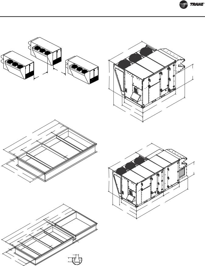
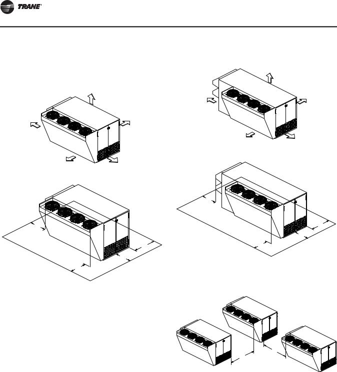
Unit Clearances
“Unit Clearances, Curb Dimensions, and Dimensional Data,” p. 12 contains figures that illustrate the minimum operating and service clearances for either a single or multiple unit installation: Figure 1, p. 12 and Figure 2, p. 12 for OA1 units,Figure 7, p. 14 through Figure 10, p. 15 for OA2 units, and Figure 15, p. 16 through Figure 18, p. 17 for OA3 units. These clearances are the minimum distances necessary to assure adequate serviceability, cataloged unit capacity, and peak operating efficiency.
Providing less than the recommended clearances may result in condenser coil starvation, “short-circuiting” of exhaust or recirculation of hot condenser air.
OAU-SVX01E-EN |
11 |
Unit Clearances, Curb Dimensions, and Dimensional
Data
 WARNING
Combustible Materials!
Maintain proper clearance between the unit heat exchanger, vent surfaces and combustible materials. Refer to unit nameplate and installation instructions for proper clearances. Improper clearances could result in a fire hazard. Failure to maintain proper clearances could result in death or serious injury or property damage.
OA1 Units
Unit Clearances
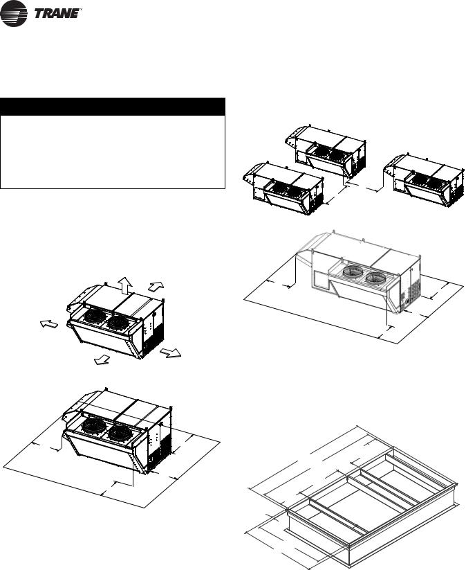
Figure 1. Typical installation clearances for OA1 unit
CLEARANCE FROM
TOP OF UNIT 72"
CLEARANCE 48"
CLEARANCE 36"
CLEARANCE 36"
CLEARANCE 60"
Figure 2. Typical installation clearances for OA1 unit with auxiliary cabinet
6'0"
7'0"
3'0"
4'0"
3'0"
3'0"
Note: Certain options require auxiliary cabinet. Refer to project-specific unit submittals.
Curb Dimensions
Figure 3. Unit curb data for OA1 5–15 tons
3'-0" |
4'-0" |
|
8 õļ
7 öļ
3'-0"
2 öļ
3'-0"
1 õļ
öļ 
4 ôļ
49ļ
õļ 
19ļ
1 ôļ
RETU
RN
SUPPLY
1.00  TYP.
TYP.
12 |
OAU-SVX01E-EN |
Unit Clearances, Curb Dimensions, and Dimensional Data
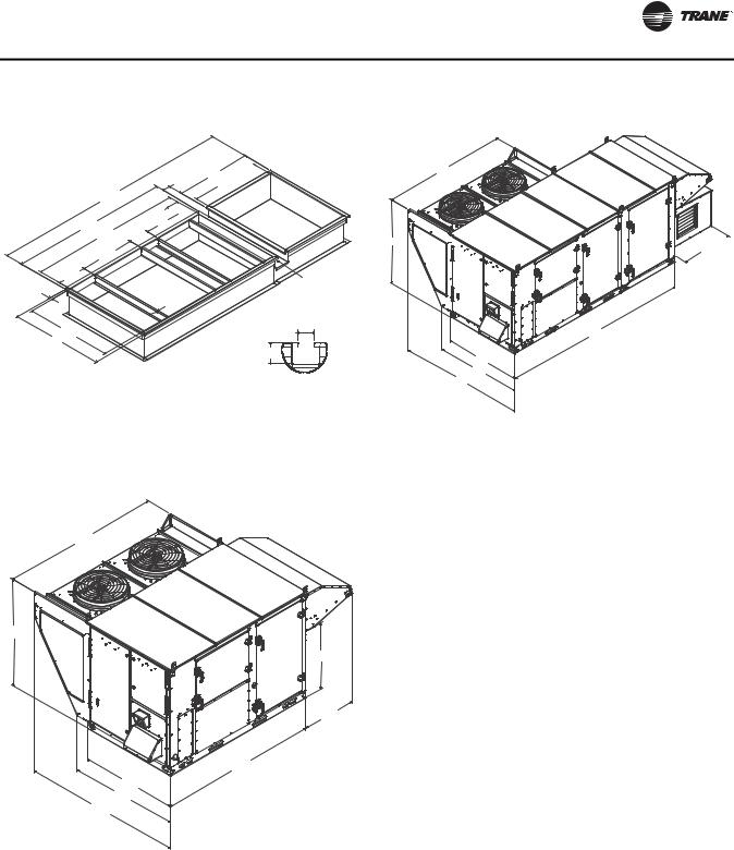
Figure 4. Unit curb data for OA1 5–15 tons with auxiliary cabinet
öļ
1 õļ
Ɍļ
12 ɍļ
õļ
8 õļ |
19" |
7 öļ |
1 ôļ |
28öļ |
|
|
S |
|
U |
|
P |
|
PL |
|
Y |
1.00
TYP.
40"  3 ôļ
3 ôļ
RETU
RN
GUTTER
|
GUTTER DETAIL |
4 ôļ |
Ɍļ |
49" |
|
|
ôļ |
Note: Certain options require auxiliary cabinet. Refer to project-specific unit submittals.
Dimensional Data
Figure 5. Unit dimensional data for OA1 5–15 tons (in.)
87.33
59.23
36.71
29.63
87.18
53.00
59.45
87.12
Figure 6. Unit dimensional data for OA1 5–15 tons with auxiliary cabinet (in.)
87.33
59.23 


 35.24
35.24
131.26
53.00
59.45
87.12
Note: Certain options require auxiliary cabinet. Refer to project-specific unit submittals.
OAU-SVX01E-EN |
13 |
Unit Clearances, Curb Dimensions, and Dimensional Data
OA2 Units
Unit Clearances
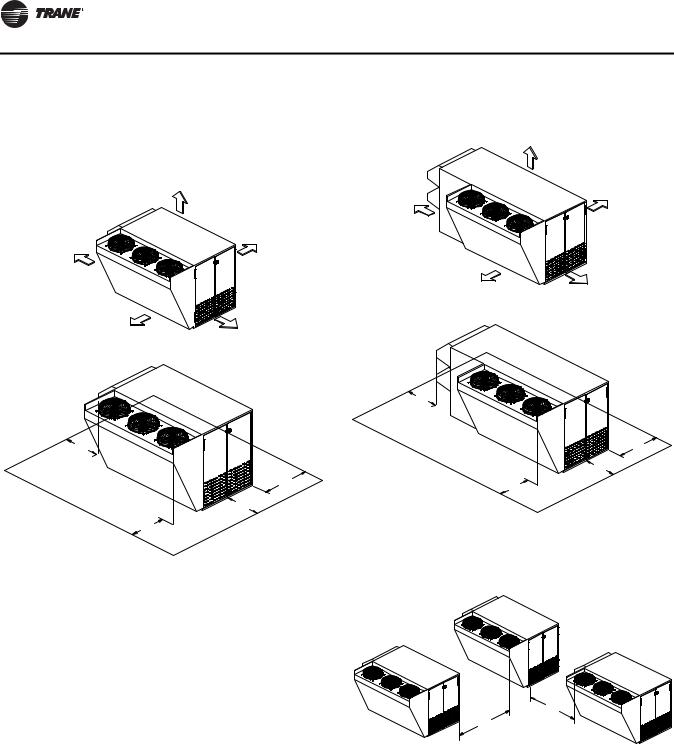
Figure 7. Typical installation clearances for OA2 unit
CLEARANCE FROM
TOP OF UNIT 72"
CLEARANCE 36" |
CLEARANCE 48" |
CLEARANCE 60" |
CLEARANCE 36" |
3'0"
4'0"
3'0"
3'0"
Figure 8. Typical installation clearances for OA2 unit with auxiliary cabinet
CLEARANCE FROM
TOP OF UNIT 72"
CLEARANCE 36" |
CLEARANCE 48" |
CLEARANCE 60" |
CLEARANCE 36" |
3'0"
4'0"
3'0"
3'0"
Note: Certain options require auxiliary cabinet. Refer to project-specific unit submittals.
Figure 9. Typical installation clearances for OA2 unit
6'0"
7'0"
14 |
OAU-SVX01E-EN |
Unit Clearances, Curb Dimensions, and Dimensional Data
Dimensional Data
Figure 10. Typical installation clearances for OA2 unit
with auxiliary cabinet
Figure 13. Unit dimensional data for OA2 12–30 tons
106.45
6'0"
7'0"
Note: Certain options require auxiliary cabinet. Refer to project-specific unit submittals.
Curb Dimensions
Figure 11. Unit curb data for OA2 12–30 tons (in.)
|
|
2 õļ |
|
ļ |
29ļ |
|
|
9 ôļ |
|
||
|
|
R |
|
|
|
ETUR |
|
30ļ |
|
N |
|
|
|
||
1 õļ |
|
1ļ |
|
|
SU |
TYP. |
|
öļ |
PPL |
||
|
|||
|
|
Y |
|
5 ôļ |
|
|
|
56ļ |
|
|
Figure 12. Unit curb data for OA2 12–30 tons with auxiliary cabinet (in.)
|
|
|
Ɍļ |
58ļ |
|
|
|
5 ôļ |
|
16 Ɍļ |
|
|
|
|
|
|
|
õļ |
|
ļ |
29ļ |
|
|
|
9 Ɏļ |
R |
|
||
|
|
|
|
|
|
|
|
ET |
|
|
|
|
|
U |
|
|
|
|
R |
30ļ |
|
|
|
N |
|
|
|
|
|
1 õļ |
|
|
1ļ |
GUTTER |
|
S |
|
TYP. |
|
|
U |
|
|
|
öļ |
|
P |
PLY |
|
|
|
|
|
GUTTER DETAIL |
|
|
|
|
Ɍļ |
5 ôļ |
|
|
|
ôļ |
56ļ |
|
|
|
|
Note: Certain options require auxiliary cabinet. Refer to project-specific unit submittals.
|
43.02 |
80.57 |
BASE TO BOTTOM |
OF AIR INLET |
106.00
60.00
135.52
66.83
94.21
Figure 14. Unit dimensional data for OA2 12–30 tons with auxiliary cabinet
62.51
106.10
43.02
BASE TO BOTTOM
OF AIR INLET
80.57


 62.11
62.11
106.00 |
200.99 |
 60.00
60.00
66.83
94.21
Note: Certain options require auxiliary cabinet. Refer to project-specific unit submittals.
OAU-SVX01E-EN |
15 |
Unit Clearances, Curb Dimensions, and Dimensional Data
OA3 Units
Unit Clearances
Figure 15. Typical installation clearances for OA3 unit
CLEARANCE FROM
TOP OF UNIT 72"
CLEARANCE 36" |
CLEARANCE 48" |
CLEARANCE 60" |
CLEARANCE 36" |
Figure 16. Typical installation clearances for OA3 unit with auxiliary cabinet
CLEARANCE FROM
TOP OF UNIT 72"
CLEARANCE 36" |
CLEARANCE 48" |
CLEARANCE 60" |
CLEARANCE 36" |
3'0"
3'0" |
|
4'0" |
|
|
|
3'0" |
|
|
4'0" |
3'0" |
|
|
3'0" |
|
|
3'0" |
Note: Certain options require auxiliary cabinet. Refer to |
||
project-specific unit submittals. |
|||
|
|||
|
Figure 17. |
Typical installation clearances for OA3 unit |
|
6'0"
7'0"
16 |
OAU-SVX01E-EN |

Unit Clearances, Curb Dimensions, and Dimensional Data
Dimensional Data
Figure 18. Typical installation clearances for OA3 unit
with auxiliary cabinet
Figure 21. Unit dimensional data for OA3 30–54 tons
6'0"
7'0"
Note: Certain options require auxiliary cabinet. Refer to project-specific unit submittals.
Curb Dimensions
Figure 19. Unit curb data for OA3 30–54 tons
|
|
|
|
|
2 õļ |
|
140ļ |
|
5 ɏļ |
RET |
|
|
13 ôļ |
|
|||
|
|
|
|
||
|
|
|
|
|
U |
|
|
|
|
|
R |
|
|
|
|
|
N |
|
33ļ |
|
|
|
|
2 ɍļ |
|
S |
|
|
1ļ |
|
|
|
TYP. |
||
|
|
U |
|
|
|
|
|
|
P |
|
|
|
|
|
PL |
|
|
öļ |
|
|
|
Y |
|
|
|
|
|
|
|
5 ôļ |
|
|
|
|
|
63ļ |
|
|
|
|
|
Figure 20. Unit curb data for OA3 30–54 tons with auxiliary cabinet
Ɍļ 5 ɏļ5 ɍļ
202ļ 2 õļ
140ļ
13 ôļ
33ļ
 2 ɍļ
2 ɍļ  öļ
öļ


 5 ôļ
5 ôļ
63ļ
5 ɏļ
SUPPLY
RETU
RN
GUTTER
1ļ TYP.
GUTTER DETAIL
Ɍļ
ôļ
Note: Certain options require auxiliary cabinet. Refer to project-specific unit submittals.
144.17
92.07
48.62
42.00
144.00
67.00
74.63 
98.49
Figure 22. Unit dimensional data for OA3 30–54 tons with auxiliary cabinet
144.17
92.07 |
35.84 |
|
|
|
62.00 |
144.00
 67.00
67.00
74.63
98.49
Note: Certain options require auxiliary cabinet. Refer to project-specific unit submittals.
OAU-SVX01E-EN |
17 |
Loading...