


Commercial Self-Contained Intellipak
Table of contents
 Loading...
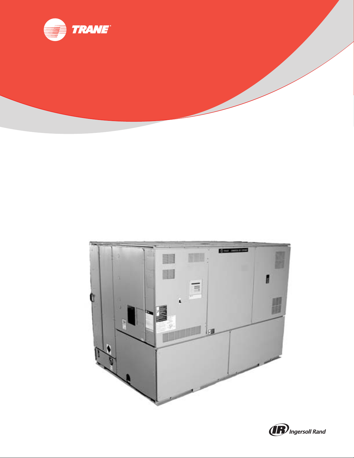
Product Catalog
Commercial Self-Contained
Intellipak™ Signature Series
Remote Air-Cooled Condenser
20 - 110 Tons — Water-Cooled
20 - 60 Tons — Air-Cooled
June 2014
PKG-PRC002U-EN
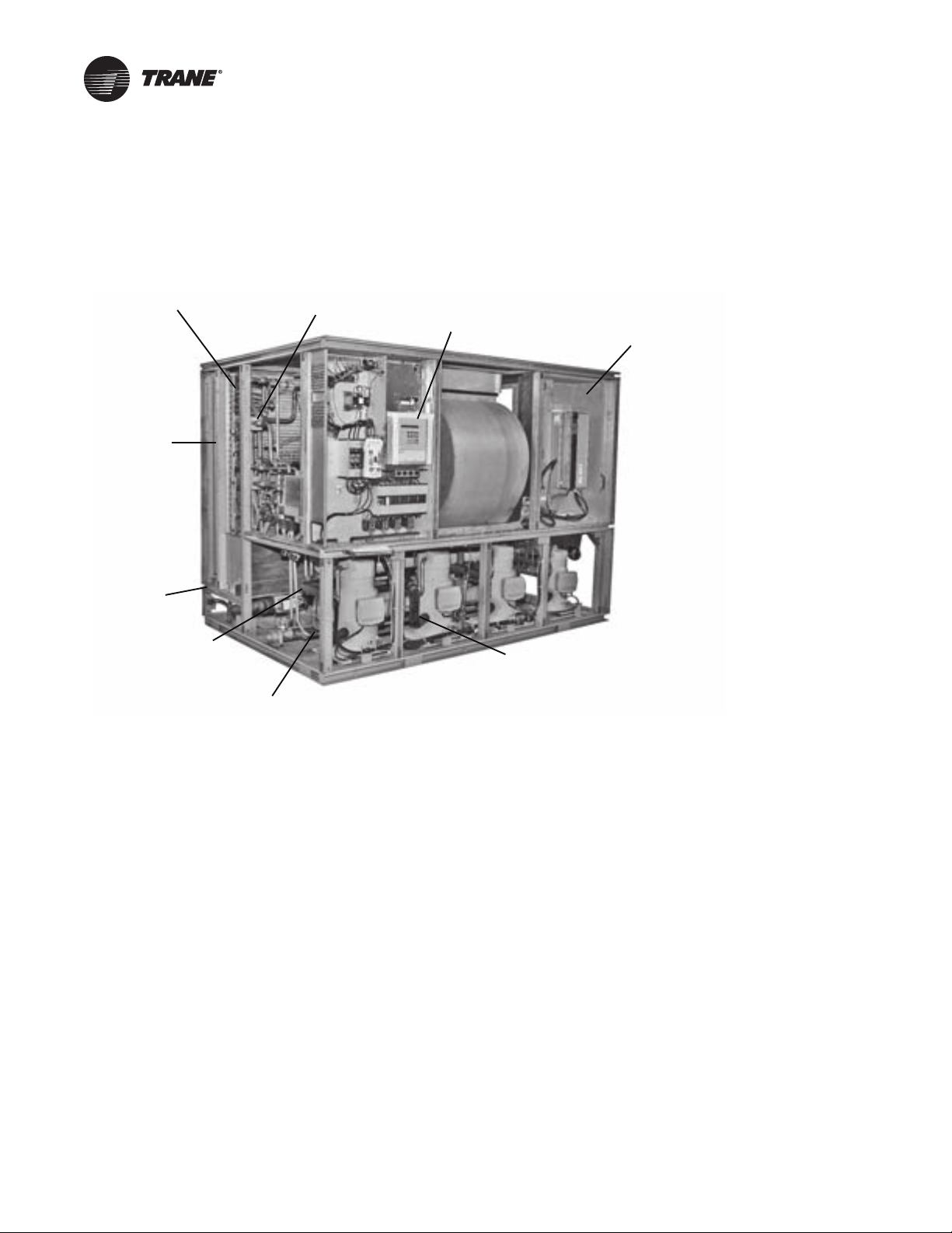
Introduction
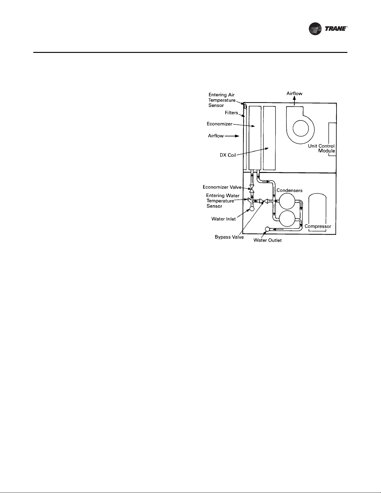
Waterside economizer
(cleanable option shown)
Sight glasses with
ports for viewing
while unit is running
Unit mounted microprocessor
control with easy-to-read human
interface panel
Swing out VFO panel with
Tri-VFO for efficie nt VAV
operation
Trane 3-D® Scroll Compressor
for reliability, efficiency and
quiet operation
Two-bolt connection on
cleanable condenser for
quick, easy maintenance
Waterside valve
package option
to enhance system
efficiency
Internally trapped
drain for low cost
installation
2-inch flat filter
box inside unit
casing
Affordable Self-Contained Value from Trane…
IntelliPak™ Signature Series Self-Contained Units
Copyright
This document and the information in it are the property of Trane, and may not be used or
reproduced in whole or in part without written permission. Trane reserves the right to revise this
publication at any time, and to make changes to its contents without obligation to notify any person
of such revision or change.
Trademarks
Trane and the Trane logo are trademarks of Trane in the United States and other countries. All
trademarks referenced in this document are the trademarks of their respective owners.
Revision History
PKG-PRC002-EN (26 Jun 2014). Updated evaporator fan and low flow fan information in
General Data tables. Reordered General Data tables
PKG-PRC002-EN (04 Apr 2013). Add wireless comm interface (WCI).
PKG-PRC002-EN (18 Oct 2012). Corrected Table 60 values. Updated fan FLA and LRA values
in Electrical Data tables.
© 2014 Trane All rights reserved PKG-PRC002U-EN

Table of Contents
Introduction ......................................................2
Affordable Self-Contained Value from Trane… ....................... 2
IntelliPak™ Signature Series Self-Contained Units .................... 2
Table of Contents ..................................................3
Features and Benefits ..............................................4
Application Considerations .........................................10
Selection Procedure ...............................................15
Model Number Descriptions ........................................17
Self-Contained Ship-With Accessory Model Number ................. 19
Remote Air-Cooled Condenser Model Number Description ............ 19
General Data .....................................................20
Performance Data ................................................27
Controls ........................................................84
IntelliPak™ Signature Series Self-Contained Units ................... 84
Zone Temperature Control Unit Sequence Of Operation .............. 92
Zone Sensor Options ........................................... 95
Electrical Data ....................................................98
Selection Procedures ........................................... 98
Determination of minimum circuit ampacity (MCA) .................. 98
Dimensions and Weights .........................................101
Field Installed Zone Sensors .................................... 112
Mechanical Specifications .........................................117
PKG-PRC002U-EN 3

Features and Benefits
Why consider Signature Series self-contained floor-by-floor systems?
Improved Cash Management
• Factory-installed and tested options reduce field labor and installation risk, while improving
system reliability
•Requires less sophisticated maintenance than built-up systems
Tenant Satisfaction
• Complete HVAC system on each floor minimizes tenant inconvenience during routine
maintenance
• Tenants can control system after hours to increase productivity and minimize expense
Low First Cost
• Reduce field labor, installation time, and cost with factory packaged controls and piping
• Reduce installed tonnage up to 20 percent by taking advantage of building diversity and VAV
flexibility
• Flexible air discharge arrangement matches most building configurations
Lower Installed Cost
• Single point power connection
• Single point water connection
• Factory commissioned and tested controls
• Factory installed options
• Internally trapped drain connection
Economical Operation
• Free cooling with waterside or airside economizer
• Energy savings with floor-by-floor system since only units on floors requiring cooling need to
operate
• Significant annual energy consumption reduction due to partial occupancy after-hours, when
compared to a central chilled water system
• Simple heating alternatives include perimeter radiation and fan-powered VAV
• Energy savings from the integrated water valve control using pump unloading
Assured Acoustical Performance
• Flexible, horizontal discharge plenum provides smooth airflow, reducing static pressure losses
for optimum acoustical performance
• Multiple compressor design reduces acoustical levels. Scroll compressor design smooths gas
flow for quieter operation
Indoor Air Quality (IAQ) Features
• Sloped drain pan
• Stainless steel sloped drain pan option
• Internally trapped drain connection
• Double wall construction option
• Matt-faced fiberglass insulation
• High efficiency throwaway filter option
4 PKG-PRC002U-EN

Features and Benefits
• Easily cleanable evaporator, condensers, and waterside economizers
• Filter access door allows easy removal to encourage frequent filter changing
• Airside economizer with Traq™ damper allows direct measurement and control of outdoor air
Enhanced Serviceability
• Self-supporting removable panels
• Quick access service panel fasteners
• Eye level control/service center
• Refrigerant line sight glasses in view during operation
Competitive Advantage
• Increased capacity to meet today’s growing floor plates and building loads
• Compact cabinet to minimize mechanical room requirements
• Up to 17% more efficient than competitive units
• Low leaving air temp capability to reduce fan motor energy, improve acoustical performance,
and minimize duct sizes
• Factory-installed and tested IntelliPak™ microprocessor controller
Standard Features
• 20 through 110 ton industrial/commercial water-cooled self-contained units
• 20 through 60 ton industrial/commercial remote air-cooled self-contained units
• Fully integrated, factory-installed, and commissioned microelectronic controls
• Unit mounted human interface panel with a two line x 40 character clear language (English,
Spanish, or French) display and a 16-function keypad that includes custom, diagnostics, and
service test mode menu keys
• Improved Trane 3-D™scroll compressor
• Compressor lead/lag
• CV or VAV system control
• Low ambient compressor lockout adjustable control input
• EISA efficiency open drip proof (ODP) and totally enclosed fan (TEFC) cooled supply fan motor
options
• FROSTAT™ coil frost protection on all units
• Daytime warm-up (occupied mode) on units with heat and morning warm-up operation on all
units
• Supply air static over pressurization protection on units with variable frequency drives (VFDs)
• Supply airflow proving
• Supply air tempering control with heating option
• Supply air heating control on VAV with hydronic heating option
• Emergency stop input
• Mappable sensors and setpoint sources
• Occupied/unoccupied switching
• Timed override activation
• Refrigeration circuits are completely factory piped and tested on water-cooled units
• Factory piped and tested, mechanically cleanable water-cooled condensers
PKG-PRC002U-EN 5

Features and Benefits
• Two-bolt removable condenser waterboxes for quick and easy cleaning
• Sloped drain pans to ensure complete condensate removal for IAQ
• Internally trapped drain connection with cleanout
• Internally isolated centrifugal supply fan
• Sturdy-gauge galvanized steel framework with easily removable painted galvanized steel
• UL listing on standard options
• Fan belts and grease lines are easily accessible
• Access panels and clearance provided to clean both evaporator and waterside economizer coil
• Condensing pressure control on all variable water flow systems with valves
• Programmable water purge during unoccupied mode
• High entering air temperature limit
• Low entering air temperature limit with waterside economizer or hydronic heat
• Shipped with protective shrink wrap covering of unit and any indoor modules shipped loose
Optional Features
• Trane communication interface module: ICS interface control module
• BACnet Communication Interface Module
• Generic BAS interface
• Comparative enthalpy control
• Ventilation override from up to five external inputs
• Remote human interface controls up to four units
• Fully integrated, factory-installed/commissioned variable frequency drive control with or
• Waterside economizer with factory installed piping and controls
• Waterside modulating condensing temperature control valves include factory installed piping
• Removable cast iron headers on cleanable waterside economizer
• Flexible horizontal discharge plenum with or without factory cut holes
• Heating options include hot water, steam, and electric
• Refrigerant suction discharge line service (shut-off) valves
• Protective coatings for the unit and/or evaporator coils
• Double wall construction
• Stainless steel sloped drain pan
• Medium efficiency throwaway filters
• Through-the-door non-fused disconnect switch
• Trane’s air quality Traq™ damper in airside economizer mixing box
• High duct temperature thermostat
• Dual electrical power connection
• CO2 reset input
• 2 and 4-inch filter racks for all sizes
• Hi-capacity coils available on many models
exterior panels
fins
without optional integrated bypass
and control wiring
6 PKG-PRC002U-EN
Variable Frequency Drives (VFD)
Var ia bl e f re quency drives are factory installed, wired, and tested to provide supply fan motor speed
modulation. VFDs are quieter and more efficient than inlet guide vanes and may even be eligible
for utility rebates. The VFDs are available with and without a manual integrated bypass option,
controlled through the human interface (HI) panel. Bypass control provides full nominal airflow
control to CV zone setpoints in the unlikely event of a drive failure by manually placing the drive
in the bypass mode.
Field Installed Accessories
• Airside economizer control with or without mixing box
• Wireless comm interface (WCI)
• Programmable sensors with or without night set back for CV and VAV systems
• ICS zone sensors used with Tracer™ system for zone control
• Field installed module kits available for field upgrade of controls
• Ultra low leak dampers for 0-100 percent modulating fresh air economizer
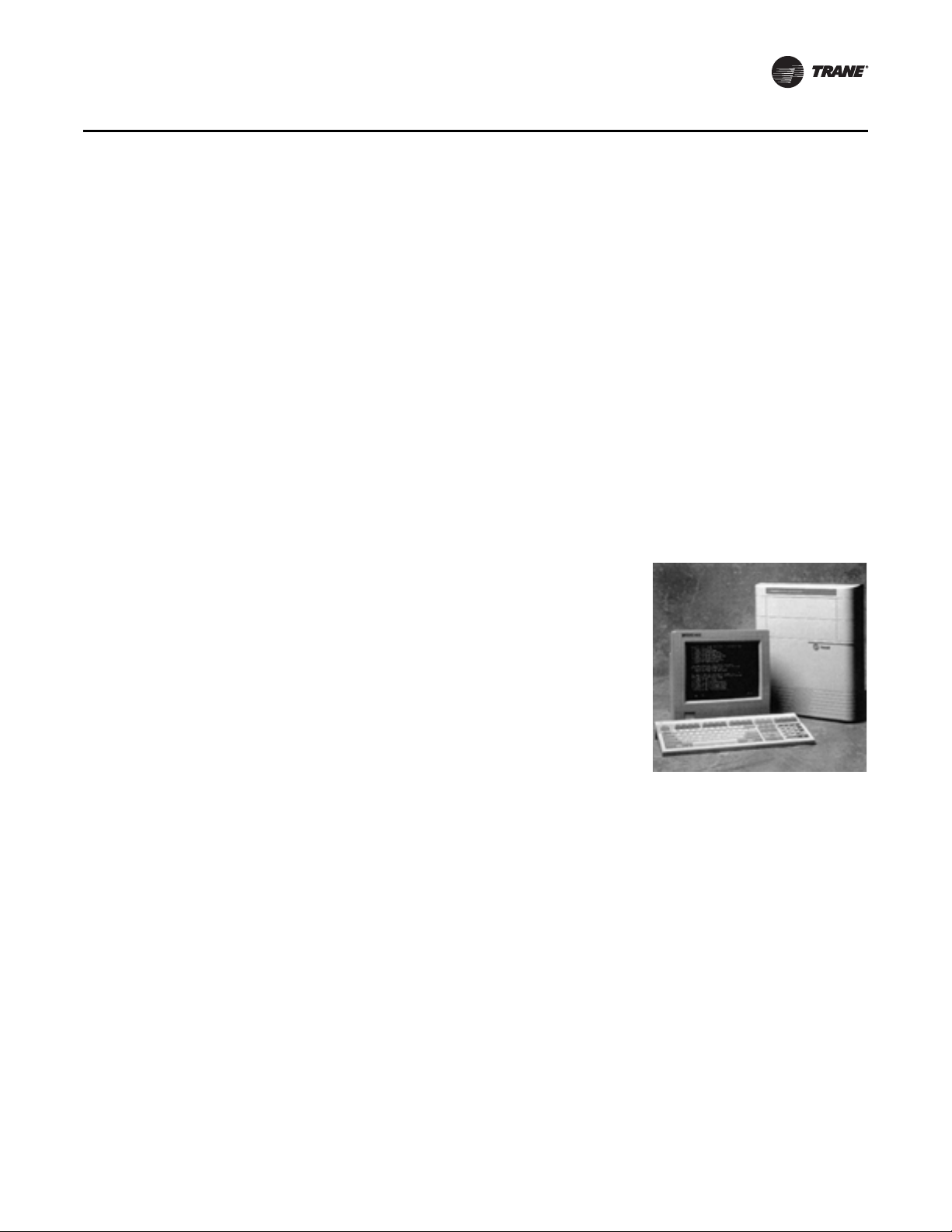
Integrated Self-Contained Systems
Integrated Comfort™ System (ICS)
Trane’s Integrated Comfort system (ICS) increases job control by
combining IntelliPak™ Signature Series self-contained units and
a Tracer™ building management system. This integrated system
provides total building comfort and control. Building owners
and managers not only save energy when using ICS. They have
the ability to automate their facilities and the convenience of a
control system interface.
Features and Benefits
Simplifying The Comfort System
Trane’s designers combined new technology and innovation to
bring you more system capabilities and flexibility. Our
Integrated Comfort System (ICS) with HVAC equipment is easy
to use, install, commission, and service.
Everything you need to know about your self-contained VAV system is available using Tracer,
Trane’s family of building automation products. Tracer is a software package that minimizes custom
programming requirements and allows easy system setup and control using your personal
computer. By enabling all CSC units to communicate using the LonTalk interface, transforming
your heating and cooling units into a true system is made simple.
Operating data from all system components is readily available for evaluation. You can control,
monitor, and service your facility—all from your personal computer. That is why all Tracer controls
have been designed to be LonTalk compatible.
The IntelliPak self-contained unit, as part of Trane ICS, provides powerful maintenance monitoring,
control, and reporting capabilities. Tracer places the self-contained unit in the appropriate
operating mode for: system on/off, night setback, demand limiting, setpoint adjustment based on
outside parameters and much more. You can monitor unit diagnostic conditions through Tracer
such as: sensor failures, loss of supply airflow, and an inoperative refrigerant circuit.
PKG-PRC002U-EN 7

Features and Benefits
Tracer points monitored for IntelliPak Signature Series Self-Contained include:
• Compressor on/off status
• Ventilation status
• Condenser water flow status
• Heat status
• Supply air pressure
• Supply air temperature
• Suction temperature of each circuit
• Entering economizer water temperature
• Zone temperature
• Entering condenser water temperature
• Supply air temperature reset signal
• Morning warm-up sensor temperature
• Entering air temperature
Tracer control points available for IntelliPak Signature Series self-contained include:
• Cooling and heating setpoints
• VAV discharge air temperature setpoints
• Supply air pressure setpoint
• Cooling and heating enable/disable
• Air economizer enable/disable
• Airside economizer minimum position
• Unit priority shutdown
Commissioning, control, efficiency, and information…it simply all adds up to one reliable
source…Trane.
Interoperability with BACnet™
The Trane Tracer SC BACnet Control Interface (BCI) for IntelliPak self-contained offers a building
automation control system with outstanding interoperability benefits. BACnet, which is an industry
standard, is an open, secure and reliable network communication protocol for controls, created by
American Society of Heating, refrigerating and Air-Conditioning Engineers, Inc. (ASHRAE).
Interoperability allows application or project engineers to specify the best products of a given type,
rather than one individual supplier's entire system. It reduces product training and installation
costs by standardizing communications across products. Interoperable systems allow building
managers to monitor and control IntelliPak equipment with Tracer SC controls or a 3rd party
building automation system. It enables integration with many different building controls such as
access/intrusion monitoring, lighting, fire and smoke devices, energy management, and a wide
variety of sensors (temperature, pressure, humidity, occupancy, CO
and air velocity).
2
Trane Wireless Comm Interface (WCI)
The Trane® Wireless Comm Interface (WCI) is the perfect alternative to Trane’s BACnet™ wired
communication links (for example, Comm links between a Tracer™ SC and a Tracer™ UC400).
Minimizing communication wire used between terminal products, zone sensors, and system
controllers has substantial benefits. Installation time and associated risks are reduced. Projects are
completed with fewer disruptions. Future re-configurations, expansions, and upgrades are easier
and more cost effective.
8 PKG-PRC002U-EN
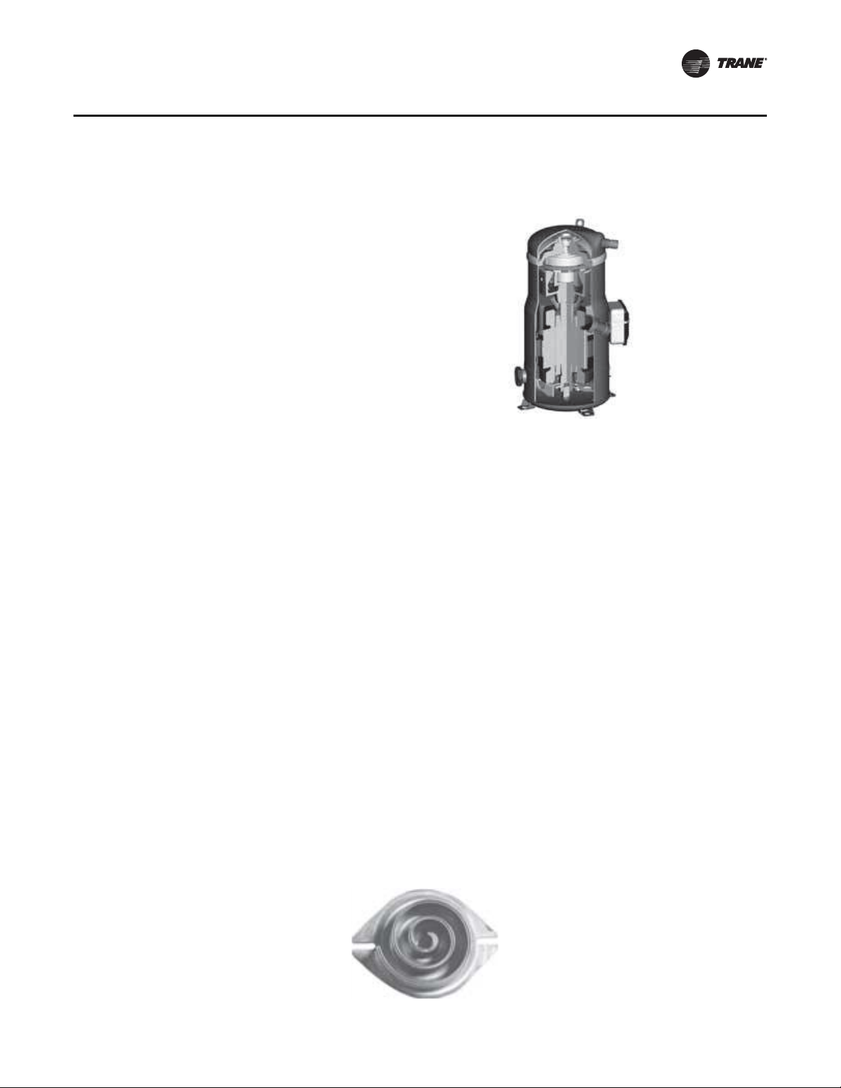
Trane R-410A 3-D™ Scroll Compressor
The R-410A Trane 3-D™ Scroll provides
important reliability and efficiency benefits
inherent in its design. The 3-D™ Scroll allows
the orbiting scrolls to touch in all three
dimensions, forming a completely enclosed
compression chamber which leads to increased
efficiency. In addition, the orbiting scrolls only
touch with enough force to create a seal,
eliminating wear between the scroll involutes.
The fixed and orbiting scrolls are made of high
strength cast iron which results in less thermal
distortion and minimal leakage. In addition,
improved part isolation provides reduced
compressor sound levels compared to previous
designs.
Features listed below optimize the compressor design and performance:
• Optimized scroll profile
• Heat shield protection to reduce heat transfer between discharge and suction gas
• Improved sealing between high side and low side
Additional features are incorporated in the compressor design for greater reliability:
• Patented design motor cap for improved motor cooling
• Improved bearing alignment
• Improved resistance to dry start-up
• Oil sight glass for evaluating proper oil levels
Features and Benefits
Low Torque Variation
The 3-D™ Scroll has a very smooth compression cycle, imposing very little stress on the motor and
resulting in greater reliability. Low torque variation reduces noise and vibration.
Suction Gas Cooled Motor
Compressor motor efficiency and reliability is further optimized with the latest scroll design. The
patented motor cap directs suction gas over the motor, resulting in cooler motor temperatures for
longer life and better efficiency.
Proven Design through Testing and Research
The new R-410A 3-D™ Scroll compressor is the next generation of reliable Trane 3-D™ Scroll
compressors provided by Trane, the leader in scroll compressor technology.
Figure 1. One of two matched scroll plates - the distinguishing feature of the scroll compressor
PKG-PRC002U-EN 9
Application Considerations
Elevator
Elevator
Supply
Air
Supply Air
Mechanical
Room
Self
Contained
Unit
Bathroom
Stairwell
Return Air
Self-Contained Acoustical Recommendations
Successful acoustical results are dependent on many system design factors.
Following are general acoustical recommendations. For more information, or if there is concern
about a particular installation, contact a professional acoustical consultant.
Location and Orientation of the Mechanical Equipment Room
Locate the equipment room adjacent to stairwells, utility rooms, electrical closets, and rest rooms
if possible (See figure below). This minimizes the acoustic effects and risk of workmanship or
installation errors. Place the discharge and return air ductwork over these less acoustically
sensitive areas, using vertical or horizontal fresh air shafts. Consult code requirements for fresh air
and smoke purge constraints.
Return Air Ductwork
Duct the return air into the mechanical equipment room. Connect ductwork to the unit if local code
dictates. The return air ductwork must have an elbow inside the equipment room. This elbow will
reduce sound transmissions through the return duct. Extend the ductwork from the elbow far
enough to block the “line of sight” to the exterior of the equipment room. Use a minimum ductwork
length of 15 feet to the equipment room exterior. Line the duct with two-inch, three-pound density
insulation. Use multiple, small return ducts for better acoustical performance to the occupied
space.
Supply Air Ductwork
Insulate the supply air duct with two-inch, three-pound density insulation. Extend this lining at least
15 feet out from the equipment room wall, keeping the duct aspect ratio as small as possible.
Minimize large flat panels since they transmit sound. In addition, small aspect ratios will minimize
potential “oil canning” of the duct due to flow turbulence.
The flexible horizontal discharge plenum option helps avoid complicated ductwork transitions.
Ductwork turning vanes typically improve pressure drop but degrade acoustical performance.
Recommended Maximum Air Velocities
The maximum recommended velocity for the discharge air duct is 2,000 fpm. The maximum
recommended velocity for the return air duct is 1,000 fpm. Limit air velocities below these
operating points to minimize the risk of flow turbulence that causes regenerated noise. Using
round supply duct and static regain allows maximum discharge air velocities up to 3,000 fpm.
Lining round supply duct also substantially lowers frequency noise attenuation. However, flow
regenerated noise potential increases dramatically at air velocities over 3000 fpm.
Figure 2. Equipment room location and orientation
10 PKG-PRC002U-EN

Application Considerations
Equipment Room Construction Options
The preferred equipment room wall construction is
concrete block. If this is not feasible then a double
stud offset wall is suggested (See figure). This
removes physical contact that would transmit sound
through the equipment room wall to the occupied
space. Interweave fiberglass insulation between the
wall studs. Use two layers of sheetrock on each side
of the wall.
Workmanship details are critical to acoustical
performance. Seal all wall and floor penetrations by
the ductwork, water piping, and equipment room
access doors with a flexible material such as caulk
and/or gasketing to stop noise and air leaks.
Locate the equipment room door away from acoustically sensitive areas like conference rooms.
The door should swing out of the equipment room, if possible, so that the low pressure in the
equipment room pulls the door in to help maintain a tight seal.
Equipment Options
The flexible horizontal discharge plenum allows multiple tested outlet options. This minimizes the
risk of acoustic and/or pressure drop problems by avoiding complex transitions close to the fan
discharge.
Static Pressure Versus Acoustics
Design the system to minimize the total static pressure required from the self-contained unit fan.
Typically a change in static pressure of only 0.5 inches can reduce NC level by approximately 2 or
3 in the occupied space.
Isolation Recommendations
Unit
The Signature Series unit fan and compressors are internally isolated. Therefore, external isolation
is not required. Consult a vibration specialist before considering external or double vibration
isolation.
Ductwork
Design duct connections to the unit using a flexible material. Consult local codes for approved
flexible duct material to prevent fire hazard potential.
Piping Connections
Rubber isolator connectors are recommended for condenser piping to prevent vibration
transmission to or from the building plumbing. The Signature Series self-contained unit is
internally isolated and does not require additional isolation. However, ensure proper system
vibration isolation design prevents vibration transmission from the building plumbing to the unit.
Also be sure to properly isolate the drain line.
Condenser Water Piping
Piping Location and Arrangement
Provide at least 24 inches of clearance between the piping and the unit for service. Place the risers
away from the side of the unit if possible. Be sure to allow sufficient space for valves and unions
between the piping and the self-contained unit. Lay out condenser piping in reverse returns to help
balance the system. This is accomplished by equalizing the supply and return pipe length. Multi-
PKG-PRC002U-EN 11

Application Considerations
story buildings may use a direct return system with balancing valves at each floor. Install all heat
exchangers and most cooling tower piping below the sump operating water level to prevent
overflow during unit and/or system shut down.
Recommended Pump Location
Locate pump downstream of the cooling tower and upstream of the self-contained unit. This
provides smoother and more stable unit operation.
When the tower and pump are both roof mounted, be sure to provide the necessary net positive
suction head pressure to prevent cavitation. Raise the tower or submerge the pump in a sump to
provide positive suction. To prevent an on-line pump failure, use a standby pump to avoid a
complete system shutdown.
Several partial capacity pumps or variable speed pumps may be used. Review the economics of
these alternate pumping options.
Strainers and Water Treatment
Water strainers are required at the unit inlet to eliminate potential unit damage from dirty water.
Specify a water basket-type strainer to avoid an incorrect stream strainer application. Untreated or
poorly treated water may result in equipment damage. Consult a water treatment specialist for
treatment recommendations.
Isolation Valves
Install isolation valves at each unit before the strainer and after the condenser. This allows periodic
servicing of the unit or strainer while allowing other units in the system to remain in operation.
Pressure Gauges
Install pressure gauges on the inlet and outlet of the self-contained unit. Select the gauge’s scale
so that the unit design operating point is approximately mid-scale.
Thermometers
Install thermometers on the condenser water inlet and outlet lines to each unit for system analysis.
Trane Company recommends using a thermometer temperature range of 40 to 140°F, using a 2°F
temperature increment.
Drains
The unit condensate drain is internally trapped to offset the pressure differential that exists during
fan operation. Install a trapped drain in the low point of the mechanical equipment room floor to
collect water from cleaning operations.
Condensing Pressure Control (Water-Cooled condensers)
Often cold condensing water applications between 35°F and 54°F require a condensing pressure
control valve. Any unit with variable-flow waterside valves can modulate water flow to maintain
a user defined condensing temperature. However, to utilize this feature, the building water system
must be capable of operating at reduced water flow rates through the self-contained units. It is
imperative to install variable volume pumps or an external bypass in the water distribution system.
12 PKG-PRC002U-EN
Waterside Economizer Flow
Control
Units equipped with waterside
economizer control valves can be set
up for variable or constant water flow.
Use constant water flow setup on
water systems that are not capable of
unloading water supply to the unit.
The economizer and condenser
valves will operate in complement to
one another to provide continuous
water flow.
Use variable water flow setup with
water flow systems that can take
advantage of pump unloading for
energy savings. Since non-cooling
operation restricts water flow during
part load economizing or condensing
temperature control, it is imperative
to install variable volume pumps or an
external bypass in the water
distribution system.
Application Considerations
Free Cooling Opportunities and Alternatives
Free cooling is available with either the airside or waterside economizer options.
Waterside Economizer
The waterside economizer substantially reduces the compressor energy requirements because it
uses the cooling water before it enters the condensers. Additional equipment room space is not
required since the coils are contained within the overall unit dimensions.
Disadvantages include higher airside pressure drop and a higher head on condenser water pumps.
The coils may be mechanically cleanable (optional) for ease in maintenance versus expensive and
difficult chemical cleaning methods.
Airside Economizer
The airside economizer substantially reduces compressor, cooling tower, and condenser water
pump energy requirements using outside air for free cooling. It also reduces tower make up water
needs and related water treatment.
Disadvantages include building requirements that locate the mechanical room and self-contained
unit toward an exterior wall to minimize ductwork, building barometric control, or additional air
shafts. Also, airside economizers require additional mechanical room space.
Unit Operating Limits
Airflow
The minimum recommended airflow for proper VAV system staging and temperature control is 35
percent of nominal design airflow. Adjusting VAV boxes with the appropriate minimum settings
will prevent the self-contained unit from operating in a surge condition at airflows below this point.
Continuous operation in a surge condition can cause fan failure. Reference General Data Tables on
Table 1, p. 20 for minimum airflow conditions.
PKG-PRC002U-EN 13

Application Considerations
Signature Series self-contained units use fixed pitch sheaves. Adjust air balancing by obtaining
alternate fixed pitch sheave selections from the local Trane sales office.
Water Flow
Use 3 gpm/ton for optimum unit capacity and efficiency. Use 2.5 or 2 gpm/ton to reduce pump
energy, cooling tower and piping costs. However, these reduced water flows may impact unit
capacity and efficiency by one or two percent. Consult General Data Tables on pages 17-20 for unit
specific water flow ranges.
Remote Air-Cooled Condenser
Unit Location
Unobstructed condenser airflow is essential to maintaining capacity and operating efficiency.
When determining unit placement, give careful consideration to assure sufficient airflow across the
condenser coils. Avoid these two detrimental conditions: warm air recirculation and coil starvation.
Both warm air recirculation and coil starvation cause reductions in unit efficiency and capacity
because of the higher head pressure associated with them. In more severe cases, nuisance unit
shutdowns will result from excessive head pressures.
Clearance
Ensure vertical condenser air discharge is unobstructed. While it is difficult to predict the degree
of warm air recirculation, a unit installed with a ceiling or other obstruction above it will experience
a capacity reduction that will reduce the maximum ambient operation limit. Nuisance high head
pressure trips may also occur.
The coil inlet must also be unobstructed. A unit installed closer than the minimum recommended
distance to a wall or other vertical riser will experience a combination of coil starvation and warm
air recirculation. This may result in unit capacity and efficiency reductions, as well as possible
excessive head pressures. Reference the service clearance section on page 111 for recommended
lateral distances.
Ambient Limitations
Standard ambient control allows operation down to 45°F with cycling of condenser fans. Units with
the low ambient option are capable of starting and operating in ambient temperatures down to 0°F.
Optional low ambient units use a condenser fan damper arrangement that controls condenser
capacity by modulating damper airflow in response to saturated condenser temperature.
Maximum ambient operating temperature of a standard condenser is 115°F. Operation at design
ambient above 115°F can result in excessive head pressures. For applications above 115°F, contact
the local Trane sales office.
14 PKG-PRC002U-EN

Selection Procedure
Following is a sample selection for a standard applied water-cooled self-contained at particular
operating conditions. Use Trane Official Product Selection System, TOPSS™, for making all final
selections or contact your local Trane representative.
Unit Capacities
1. Determine entering air temperature dry bulb and wet bulb and entering water temperature.
2. See chapter “Performance Data,” p. 27 to find gross total and sensible capacity that best meets
capacity requirements.
3. Apply the cfm correction factors from the capacity correction factor Ta bl e 13, p. 37 to determine
gross total and gross sensible capacities at desired cfm.
4. Multiply condenser water delta T by the total capacity cfm correction factor to determine new
condenser water delta T.
5. Using design cfm, determine static air pressure drops for accessories from the air pressure
drop Charts
external supply and return static air pressure drops. Use the total air pressure drop to determine
rpm and brake horsepower requirements from the appropriate fan curve. Note: The fan curves
include refrigerant coil and internal cabinet static loses.
6. Calculate supply fan motor heat by using the following equation:
Fan motor heat (MBh) = 2.8 x fan motor brake horsepower
7. Determine net total capacity and net sensible capacity by subtracting fan motor heat from gross
total capacity and gross sensible capacity.
8. Refer to Trane psychometric chart to determine leaving air temperatures.
Figure 1, p. 27 through Figure 21, p. 33. Add accessory static pressure drops to
Waterside Economizer Capacity
After determining that the unit will meet the required mechanical cooling capacity, determine the
waterside economizer capacity by referring to the appropriate two-row (low capacity) or four-row
(high capacity) waterside economizer capacity found in one of Table 15, p. 38 through Ta b le 48 ,
p. 72.
9. Determine entering air temperature dry bulb and wet bulb, condenser water flow (gpm), and
economizer entering water temperature.
10. Refer to the appropriate waterside economizer table to find gross total and sensible capacity
and the leaving water temperature.
11. Apply the cfm correction factor for the waterside economizer from the appropriate table to
determine the gross total and sensible capacities at the desired cfm.
12. Multiply the condenser water delta T by the total capacity cfm correction factor to determine
the new delta T.
13. Calculate supply fan motor heat by using the following equation:
Fan motor heat (MBh) = 2.8 x fan motor brake horsepower
14. Determine net total and sensible capacity by subtracting fan motor heat from gross total and
sensible capacity.
15. Refer to the Trane psychometric chart to determine leaving air temperatures.
Selection Example
Design Conditions
Total gross capacity required = 420 MBh = 35.2 Tons
Total sensible capacity required = 315 MBh
Entering air temperature = 80/67°F
PKG-PRC002U-EN 15

Selection Procedure
Unit includes:
Unit Selection
Tentatively select a 35 ton unit: Model SCWF 35.
Refer to Table 26, p. 49 to obtain gross total and sensible unit capacities, and gpm at the design
conditions:
Since the design cfm is greater than the nominal cfm, adjust the capacities and condenser water
delta T to reflect the higher cfm: design cfm 14840 = +6% of nom. Cfm nominal 14000 cfm
Refer to Tab l e 1 3 , p. 37 to obtain the capacity correction factors for +6% of nominal cfm:
Multiply the capacities by the correction factors:
The SCWF 35 meets the total and sensible design requirements.
Multiply the delta T of 10.1°F by the cooling capacity correction factor of 1.009 to obtain new delta
T of 10.19°F and add this to the entering water temperature to obtain the actual leaving water
temperature of 95.19°F.
Entering water temperature = 85°F
Water flow rate = 105 gpm
Airflow = 14840 cfm at 2.5-inch duct static pressure
• Constant Volume
• Waterside economizer
• Medium velocity throwaway filters
Total capacity = 432.0 MBh
Sensible capacity = 329.0 MBh
Leaving water temperature = 95.1°F
Cooling capacity multiplier = 1.009
Sensible capacity multiplier = 1.027
• 432 MBh x 1.009 = 435.89 MBh
• 329 MBh x 1.027 = 337.88 MBh
16 PKG-PRC002U-EN

Model Number Descriptions
Self-Contained
Digit 1 - Unit Model
S = Self Contained
Digit 2 - Unit Type
C = Commercial
I = Industrial
Digit 3 - Condenser Medium
W = Water-cooled
R = Air-cooled
Digit 4 - Development Sequence
F = Signature Series
Digit 5 - Refrigerant Circuit
Configuration
U = Standard Capacity
V = High Capacity
Digit 6, 7 - Unit Nominal
Capacity
20 = 20 tons (water or air)
22 = 22 tons (water only)
25 = 25 tons (water or air)
29 = 29 tons (water or air)
30 = 30 tons (air only)
32 = 32 tons (water only)
35 = 35 tons (water or air)
38 = 38 tons (water only)
40 = 40 tons (air only)
42 = 42 tons (water only)
46 = 46 tons (water only)
50 = 50 tons (air only)
52 = 52 tons (water only)
58 = 58 tons (water only)
60 = 60 tons (air only)
65 = 65 tons (water only)
72 = 72 tons (water only)
80 = 80 tons (water only)
90 = 90 tons (water only)
C0 =100 tons (water only)
C1 =110 tons (water only)
Digit 8 - Unit Voltage
6 = 200 volt/60 hz/3 ph
4 = 460 volt/60 hz/3 ph
5 = 575 volt/60 hz/3 ph
Digit 9 - Air Volume/Temp
Control
2 = VFD and supply air temp ctrl
3 = VFD w/ bypass and supply
air temp ctrl
4 = Constant volume, zone temp cool
only
5 = Constant volume, w/ zone temp
heat/cool
6 = Constant volume and supply air
temp ctrl
Digit 10, 11 - Design Sequence
** = Factory Assigned
Digit 12 - Unit Construction
A = Vertical Discharge
B = Vertical Discharge With Double Wall
Digit 13 - Flexible Horizontal
Discharge Plenum Type
B = STD plenum w/ factory-cut holes
C = Low plenum w/ factory-cut holes
E = Std plenum w/ field-cut holes
F = Low plenum w/ field-cut holes
H = STD plenum double wall w/ field-cut
holes
J = Low plenum double wall w/ field-cut
holes
K = Extended height plenum w/factory-cut
holes, ship separate
L = STD plenum w/factory-cut holes, ship
separate
M =Low plenum w/factory-cut holes, ship
separate
N = Extended height plenum w/field-cut
holes, ship separate
P = STD plenum w/field-cut holes, ship
separate
R = Low plenum w/field-cut holes, ship
separate
T = Extended height double-wall plenum
w/ field-cut holes, ship separate
U = STD double-wall plenum w/field-cut
holes, ship separate
V = Low double-wall plenum w/field-cut
holes, ship separate
W =STD double-wall (perf) plenum
w/field-cut holes (90-110 ton only)
X = Low double-wall (perf) plenum
w/field-cut holes (90-110 ton only)
Y = Extended height double-wall (perf)
plenum w/field-cut holes, ship
separate (90-110 ton only)
0 = None
Digit 14 - Motor Type
2 = ODP motor
3 = TEFC motor
Digit 15, 16 - Motor HP
05 = 5 hp
07 = 7.5 hp
10 = 10 hp
15 = 15 hp
20 = 20 hp
25 = 25 hp
30 = 30 hp
40 = 40 hp
50 = 50 hp (400V, 460V, 575V only)
60 = 60 hp (90-110 ton only)
Digit 17, 18, 19 - Fan rpm
040 = 400 rpm
045 = 450 rpm
050 = 500 rpm
052 = 525 rpm
055 = 550 rpm
057 = 575 rpm
060 = 600 rpm
065 = 650 rpm
070 = 700 rpm
075 = 750 rpm
080 = 800 rpm
085 = 850 rpm
090 = 900 rpm
095 = 950 rpm
100 = 1000 rpm
105 = 10 50 rpm
110 = 11 0 0 r pm
115 = 1150 rpm
120 = 1200 rpm
125 = 1250 rpm
130 = 1300 rpm
135 = 1350 rpm
Digit 20 - Heating Type
A = Steam coil
B = Hot water coil
C = Electric heat, 1 stage
D = Electric Heat (2 Stage)
F = Hydronic heat ctrl interface
G = Elec. heat ctrl interface, 1 stage
H = Elec. heat ctrl interface, 2-stage (90-
110 ton only)
J = Elec. heat ctrl interface, 3 stage (90-1
10 ton only)
K = Steam coil ship separate, LH
L = Hot water coil ship separate, LH
T = Hot water coil, high capacity, LH
U = Hot water coil, high capacity, LH, ship
separate
0 = None
Digit 21 - Unit Isolators
A = Isopads
B = Spring isolators
0 = None
Digit 22 - Unit Finish
1 = Paint - slate gray
2 = Protective coating
3 = Protective coating w/ finish coat
Digit 23 - Supply Fan Options
0 = Standard fan
1 = Low CFM fan
Digit 24 - Unit Connection
1 = Disconnect switch
2 = Terminal block
3 = Dual point power (2 blocks)
PKG-PRC002U-EN 17

Model Number Descriptions
Digit 25 - Industrial Options
A = Protective coating evaporator coil
B = Silver solder
C = Stainless steel screws
D = A and B
E = A and C
F = B and C
G = A, B, and C
0 = none
Digit 26 - Drain Pan Type
A = Galvanized sloped
B = Stainless steel sloped
Digit 27 - Waterside Economizer
A = Mechanical clean full capacity (4-row)
B = Mechanical clean low capacity (2-row)
C = Chemical clean full capacity (4-row)
D = Chemical clean low capacity (2-row)
0 = None
Digit 28 - Ventilation Control
B = Airside econ w/ Traq damper, top O/A
C = Airside econ w/ std damper, top O/A
E = Airside econ w/ Traq damper &
comparative enthalpy, top O/A
F = Airside econ w/ std damper &
comparative enthalpy, top O/A
H = 2-position damper ventilation
interface
J = Airside economizer interface
K = Airside economizer interface w/
comparative enthalpy
Digit 29 - Water Piping
D = Left hand basic piping
F = Left hand Intermediate piping
K = Left hand basic w/ flow switch
M = Left hand intermediate w/ flow switch
0 = None
Digit 30 - Condenser Tube Type
A = Standard condenser tubes
B = 90/10 CuNi condenser tubes
0 = None (air-cooled only)
Digit 31 - Compressor Service
Valves
1 = With service valves
0 = None
Digit 32 - Miscellaneous System
Control
1 = Timeclock
2 = Interface For remote HI (IPCB)
3 = Dirty filter switch
4 = 1 and 2
5 = 1 and 3
6 = 2 and 3
7 = 1, 2 and 3
0 = None
G = GBAS and VOM
H = GBAS and RHI
J = VOM and RHI
M =GBAS, VOM, and RHI
N = BACnet Communications Interface
(BCI)
P = BCI and GBAS
Q = BCI and VOM
R = BCI and RHI
T = BCI and GBAS and VOM
U = BCI and GBAS and RHI
V = BCI and VOM and RHI
W= BCI and GBAS and VOM and RHI
0 = None
1 = Lontalk Comm5 Interface (LCI)
2 = LCI and GBAS
3 = LCI and VOM
4 = LCI and RHI
5 = LCI and GBAS and VOM
6 = LCI and GBAS and RHI
7 = LCI and VOM and RHI
8 = LCI and GBAS and VOM and RHI
Digit 34 - Agency
T = UL agency listing
0 = None
Digit 35 - Filter Type
1 = 2” T/A w/ 2” rack
2 = 2” med. eff. T/A w/ 2” rack
3 = 4” bolt-on rack w/ 2” med eff. filter
4 = 6” rack w/ 2” construction T/A
pre-filter & 4” filter space
5 = 6” rack w/ 2” med. eff. T/A pre-filter &
4”filter space
Digit 36 - Miscellaneous Control
Option
A = Low entering air temp. protect device
(LEATPD)
B = High duct temp t-stat, ship separate
C = Plenum high static switch, ship
separate
E = A and B
F = A and C
H = B and C
L = A, B, and C
0 = None
Digit 33 - Control Interface
Options
A = Generic BAS Module; 0-5 VDC (GBAS)
B = Ventilation Override Module (VOM)
D = Remote Human Interface (RHI)
18 PKG-PRC002U-EN

Model Number Descriptions
Self-Contained ShipWith Accessory
Model Number
Digit 1 - Parts/Accessories
P = parts/accessories
Digit 2 - Unit Model
S=self-contained
Digit 3 - Shipment
W = with unit
Digit 4 - Development Sequence
F = signature series
G = modular series
Digit 5 - Sensors and Other
Accessories
S = sensors
Digit 6 - Sensors and
Thermostats (Field Installed)
A = BAYSENS077 - zone temp only
(CV and VAV)
B = BAYSENS073- zone temp with
timed override button (CV and
VAV)
C = BAYSENS074 - zone temp with
timed override button, setpoint
dial (CV and VAV)
E = BAYSENS108 - CV zone sensor
-dual setpoint, man/auto
changeover
F = BAYSENS110 - CV zone sensor-
dual setpoint, man/auto
changeover w, indicastor lights
G = BAYSENS119 - CV/VAV program-
mable night setback Sensor
H = BAYSENS021 - VAV zone sensor
with indicator lights
L = outside air temperature sensor kit
M = outside air humidity sensor kit
0 = none
Digit 7 - Mixed Air Temperature
Protection Kit (Field Installed)
1 = mixed air temperature protection
kit
0 = none
Digit 8 - Carbon Dioxide Sensor
(Field Installed)
1 = carbon dioxide sensor kit
0 = none
Digit 9 - Future Option
0 = none
Digits 10, 11 - Design Sequence
** = Factory Assigned
Remote Air-Cooled Condenser Model Number Description
Digit 1 - Unit Model
C = Condenser
Digit 2 - Unit Type
C = Commercial
I = Industrial
Digit 3 - Condenser Medium
R = Remote
Digit 4 - Development Sequence
C = C
Digit 5, 6, 7 - Nominal Capacity
020 = 20 tons
029 = 29 tons
035 = 35 tons
040 = 40 tons
050 = 50 tons
060 = 60 tons
Digit 8 - Unit Voltage
4 = 460 volt/60 hz/3 ph
5 = 575 volt/60 hz/3 ph
6 = 200 volt/60 hz/3 ph
Digit 9 - Control Option
0 = No low ambient damper, I-Pak.
A = No low ambient damper, t-stat.
B = Low ambient, I-Pak.
C = Low ambient, t-stat.
Digit 10, 11 - Design Sequence
** = Factory Assigned
Digit 12 - Unit Finish
1 = Paint, slate gray
2 = Protective coating
3 = Protective coating with
finish coat
Digit 13 - Coil Options
A = Non-coated aluminum
C = Protective coating aluminum
Digit 14 - Unit Isolators
0 = None
A = Spring isolators
B = Isopads
Digit 15 - Panels
1 = Louvered panels
Digit 16 - Agency Listing
0 = None
U = With UL listing
PKG-PRC002U-EN 19
General Data
Table 1. SCWF/SIWF Water-cooled self-contained, 20 to 42 tons
Unit Size 20 22 25 29 32 35 38 42
Compressor Data
Quantity 2 2 2 1/1 1/1 3 3 2/1
Nominal Ton/comp 10 10 10 15/10 15/10 10 10 10/15
Circuits 222223 33
Evaporator Coil Data
Rows 2 2 3 or 6 2 4 or 6 3 4 or 6 3
Sq. Ft. 21.81 21.81 21.81 29.98 29.98 31.35 31.35 38.57
Fpf 144 144 144 144 144 144 144 144
Condenser Data
Minimum Gpm W/o Econ 36 36 36 46 46 54 54 64
Minimum Gpm W/ Econ 41 41 41 60 60 65 65 64
Maximum Gpm 80 80 80 102 102 119 119 142
Evaporator Fan Data
Quantity 11111111
Diameter 18” 18” 18” 18” 18” 20" 20" 25”
Minimum Hp 55555557. 5
Minimum Kw (3.73) (3.73) (3.73) (3.73) (3.73) (3.73) (3.73) (5.39)
Maximum Hp 20 20 20 20 20 25 25 30
Maximum Kw (14.91) (14.91) (14.91) (18.64) (18.64) (18.64) (18.64) (22.37)
Minimum Design Cfm 6325 6325 6500 8700 8700 9100 9880 11200
Maximum Design Cfm 8500 9350 10625 12325 13600 14875 16150 17850
High Capacity Option
Rows — — 6 — 6 — 6 —
Optional Low Flow Fan
Diameter — — — — 18” —
Min/max Design Cfm — — — — 6000/10625 —
General Data R-410A
EER 14.0 14.0 14.0 14.0 14.3 14.0 14.2 14.2
IEER (CV) 15.3 15.3 15.0 15.6 15.2 15.2 14.9 15.6
IEER (VAV) 17.4 17.4 17.5 18.1 18.8 18.0 18.5 18.3
Refrigerant Charge, lbs. R-410A
Circuit A 19.5 19.5 21.5 22.0 28.5 21.5 23.5 22.0
Circuit B 19.5 19.5 21.5 19.5 23.5 21.5 23.5 22.0
Circuit C – – – – – 21.5 23.5 22.0
Capacity Steps - % 100/53/0 100/53/0 100/53/0 100/62/39/0 100/59/39/0 100/65/31/0 100/65/30/0
Notes:
1. Compressors are Trane 3-D™ scroll.
2. EER and IEER are rated in accordance to AHRI Standard 340/360-2010. Based on 80/67° F (26.7/19.4 °C) to evaporator coil, nominal airflow and
85-95 °F (29.4/35 °C) condenser water.
3. All units operate with R-410A. Units ships with full operating charge.
4. Maximum cfm limits are set to prevent moisture carryover on the evaporator coil.
5. Minimum cfm limits are set to ensure stable thermal expansion valve operation at low load conditions.
6. Optional low flow fan (unit model number digit 23 = 1) is available ONLY when High Capacity option is selected (unit model number digit 5 = V).
6
100/71/
43/26/0
20 PKG-PRC002U-EN

General Data
Table 2. SCWF/SIWF Water-cooled self-contained, 46-110 tons
Unit Size 46 52 58 65 72 80 90 100 110
Compressor Data
Quantity 2/1 3 3 3/1 3/1 4 5 2/4 6
Nominal Ton/Comp 10/15 15 15 15/10 15/10 15 15 10/15 15
Circuits 3 33444566
Evaporator Coil Data
Rows 4 or 6 2 4 or 6 3 4 or 6 6 6 6 6
Sq. Ft. 38.57 49.09 49.09 49.09 49.09 49.09 56.81 56.81 56.81
FPF 144 144 144 144 144 144 144 144 144
Condenser Data
Min GPM w/o Econ 64 84 84 102 102 112 140 168 168
Min GPM w/ Econ 64 84 84 102 102 112
Maximum GPM 142 186 186 226 226 248 300 350 350
Evaporator Fan Data
Quantity 1 11111111
Size (Dia.) 25” 25” 25” 27.5” 27.5” 27.5” 27.5” 27.5” 27.5”
Minimum HP 7.5 10 10 10 10 10 15 15 15
Minimum kW (5.59) (7.46) (7.46) (7.46) (7.46) (7.46) (11.19) (11.19) (11.19)
Maximum HP 30 50 50 50 50 50 60 60 60
Maximum kW (22.37) (37.29) (37.29) (37.29) (37.29) (37.29) (44.74 ) (44.74) (44.74)
Min Design CFM 11960 14250 15080 16900 18700 20800 17500 17500 17500
Max Design CFM 19550 22100 24650 27625 29800 29800 35000 35000 35000
High Capacity Option
Rows 6—6—6—888
Optional Low Flow Fan
Size (Dia.) 18” 18” 20”
Min./Max Design CFM 7700/13600 —
General Data R-410A
EER 14.3 14.0 14.3 14.0 14.0 14.0 14.1 14.1 14.0
IEER (CV) 15.2 15.7 15.3 15.4 14.9 14.6 16.3 16.3 16.3
IEER (VFD) 18.8 17.9 18.9 18.2 18.5 19.3 18.6 18.5 18.1
Refrigerant Charge — lbs. R-410A
Circuit A 24.5 21.0 26.5 22.0 24.5 28.0 24.5 24.5 24.5
Circuit B 24.5 21.0 26.5 22.0 24.5 28.0 24.5 24.5 24.5
Circuit C 24.5 21.0 26.5 22.0 24.5 28.0 24.5 24.5 24.5
Circuit D – – – 21.0 22.0 28.0 24.5 24.5 24.5
Circuit E – – – – – – 24.5 24.5 24.5
Circuit F – – – – – – – 24.5 24.5
Capacity Steps - % 100/70/41/30/0
Notes:
1. Compressors are Trane 3-D™ scroll.
2. EER and IEER are rated in accordance to ARI Standard 340/360-2 007. Based on 80/6 7° F (26.7/19.4 ° C) to ev apor ator coil, no minal airflow and 85-
95 °F (29.4/35 °C) condenser water.
3. All units operate with R-410A. Units ships with full operating charge.
4. Maximum cfm limits are set to prevent moisture carryover on the evaporator coil.
5. Minimum cfm limits are set to ensure stable thermal expansion valve operation at low load conditions.
100/65/
32/0
8900/
13600
100/65/
30/0
—
100/71/
44/24/0
10700/
16150
100/71/43/
23/0
—
100/73/46/
20/0
100/80/40/
20/0
100/75/38/
19/0
100/66/33/
17/0
PKG-PRC002U-EN 21

General Data
Table 3. SCRF/SIRF Air-cooled self-contained
Unit Size 20 25 29 30 35 40 50 60
Compressor Data
Quantity 21/11/13 32/13 4
Nominal Ton/Comp 10 15/10 15/10 10 10 10/15 15 15
Circuits 22222222
Evaporator Coil Data
Rows 32434446
Sq. Ft. 21.81 29.98 29.98 31.35 31.35 38.57 49.09 49.09
FPF 144 144 144 120 144 144 144 144
Evaporator Fan Data
Quantity 11111111
Size (Dia.) 18” 18” 18” 20” 20” 25” 25” 27.5”
Minimum HP 555557.51010
Minimum kW (3.73) (3.73) (3.73) (3.73) (3.73) (5.59) (7.46) (7.46)
Maximum HP 20 20 20 25 25 30 40 50
Maximum kW (14.91) (18.64) (18.64) (18.64) (18.64) (22.37) (37.29) (37.29)
Minimum Design CFM 6500 8700 8700 9100 9880 11960 15080 20800
Maximum Design CFM 10625 12325 13600 14875 16150 19550 24650 29800
General Data
EER 10.0 10.0 10.5 10.4 10.6 10.7 10.5 10.3
IEER (CV) 10.8 11.6 12.2 12.5 12.0 12.7 12.1 11.2
IEER (VAV) 11.9 12.8 13.7 13.5 13.9 14.4 13.7 14.1
Refrigerant Charge See Note 6
Capacity Steps - % 100/53/0 100/62/39/0 100/59/39/0 100/65/31/0 100/65/30/0
CCRC/CIRC Unit Match 20 29 29 35 35 40 50 60
Notes:
1. Compressors are Trane 3-D™ scroll.
2. EER and IEER are rated in accordance to ARI Standard 340/360-2007. Based on 80/67° F (26.7/19.4 °C) to evaporator coil, nominal airflow and 85-
95 °F (29.4/35 °C) condenser water.
3. All units operate with R-410A. Units ship with a dry nitrogen holding charge. Field refrigerant system charge required. Refer to Table 5, p. 23 for
amounts required.
4. Maximum cfm limits are set to prevent moisture carryover on the evaporator coil.
5. Minimum cfm limits are set to ensure stable thermal expansion valve operation at low load conditions.
100/70/41/
30/0
100/65/30/0
100/73/46/
20/0
22 PKG-PRC002U-EN

General Data
Table 4. CCRC/CIRC Remote air-cooled condenser
Unit Size 20 29 35 40 50 60
Condenser Fan Data
Number/Type/Drive 4/Prop/Direct 4/Prop/Direct 6/Prop/Direct 6/Prop/Direct 8/Prop/Direct 8/Prop/Direct
Size (inches) 26 26 26 26 26 26
Size (mm) (660.4) (660.4) (660.4) (660.4) (660.4) (660.4)
HP ea. 111111
Nominal CFM 18,800 21,200 35,600 39,800 46,200 56,400
Nominal (liters / sec) (8873) (10005) (16801) (18784) (21804) (26618)
Condenser Coil Data
Circuit 1 Size (in.) 1/46x71 1/64x71 2/46x71 2/46x71 2/64x71 2/64x71
Circuit 1 Size (mm) (1/1168x1803) (1/1626x1803) (2/1168x1803) (2/1168x1803) (2/1626x1803) (2/1626x1803)
Circuit 2 No./Size (in.) 1/46x71 1/46x71 1/46x71 1/64x71 1/64x71 2/64x71
Circuit 2 No./Size (mm) (1/1168x1803) (1/1168x1803) (1/1168x1803) (1/1626x1803) (1/1626x1803) (2/1626x1803)
Face Area (sq. ft.) 45.4 54.2 68 76.9 94.7 126.2
Face Area (sq.m) (4.2) (5) (6.3) (7.1) (8.8) (11.7)
Rows/fpf 4/144 4/144 4/144 4/144 4/144 4/144
Ambient Temperature Operating Range
Standard Ambient (F) 50-115 50-115 50-115 50-115 50-115 50-115
Standard Ambient (C) (10 - 46.1) (10 - 46.1) (10 - 46.1) (10 - 46.1) (10 - 46.1) (10 - 46.1)
Low Ambient Option (F) 0-115 0-115 0-115 0-115 0-115 0-115
Low Ambient Option (C) (-17.8 - 46.1) (-17.8 - 46.1) (-17.8 - 46.1) (-17.8 - 46.1) (-17.8 - 46.1) (-17.8 - 46.1)
Note: Units ship with dry nitrogen charge. field refrigerant system charge required. See Table 5 for amounts required.
Table 5. SCRF/SIRF Air–cooled self–contained and CCRC/CIRC remote air-cooled condenser refrigerant data
SCRF/SIRF & CCRC/CIRC
Unit Size 20/20 25/29 29/29 30/35 35/35 40/40 50/50 60/60
No. of Refrigerant Circuits 22222222
Operating Charge - lbs. R-410A 35.5/35.5 44.5/33.5 51/37.5 71/35.5 75/37.5 86.5/39.5 98/50 101.5/101.5
Operating Charge - kg R-410A 16.1/16.1 20.2/15.2 23.1/17 32.2/16.1 34/17 39.2/17.9 44.5/22.7 46/46
Cond. Storage Cap. - lbs. R-410A 37/37 51/37 51/37 74/37 74/37 74/51 102/51 102/102
Cond. Storage Cap. - kg R-410A 16.8/16.8 23.1/16.8 23.1/16.8 33.6/16.8 33.6/16.8 33.6/23.1 46.3/23.1 46.3/46.3
Notes:
1. Refrigerant charges are listed as circuit 1 circuit 2 and provide only an estimate. Final charge requires sound field charging practice.
2. Operating charge is for entire system, which includes the air–cooled self–contained, remote air–cooled condenser, and 25 feet of interconnecting
refrigerant piping.
3. At conditions of 95° F (35° C), condenser storage capacity is 95% full.
4. To determine the correct amount of refrigerant needed for a particular application, reference the Trane Reciprocating Refrigeration Manual.
Table 6. SCWF/SIWF water flow volumes
Water Volume in U.S. Gallons / Liters
Unit
Size
W/o Economizer
Gallons Liters Gallons Liters Gallons Liters
20 9.0 34.1 17.4 65.9 16.9 64.0
22 9.0 34.1 17.4 65.9 16.9 64.0
25 9.0 34.1 17.4 65.9 16.9 64.0
With Mech. Cleanable
Econ
With Chem.
Cleanable Econ
PKG-PRC002U-EN 23
General Data
Table 6. SCWF/SIWF water flow volumes (continued)
Water Volume in U.S. Gallons / Liters
Unit
Size
100 23.0 87.1 50.6 191.5 N/A N/A
110 24.0 90.8 51.6 195.3 N/A N/A
W/o Economizer
29 9.0 34.1 20.5 77.6 18.8 71.2
32 9.0 34.1 20.5 77.6 18.8 71.2
35 10.0 37.9 21.9 82.9 20.2 76.5
38 10.0 37.9 21.9 82.9 20.2 76.5
42 15.0 56.8 32.2 121.9 31.4 118.9
46 15.0 56.8 32.2 121.9 31.4 118.9
52 15.0 56.8 36.9 139.7 35.9 135.9
58 15.0 56.8 36.9 139.7 35.9 135.9
65 16.0 60.6 37.9 143.5 36.9 139.7
72 16.0 60.6 37.9 143.5 36.9 139.7
80 16.0 60.6 37.9 143.5 36.9 139.7
90 22.5 85.2 50.1 189.6 N/A N/A
With Mech. Cleanable
Econ
With Chem.
Cleanable Econ
Table 7. SCWF/SIWF Refrigerant circuits, number of compressors by circuit
Circuit
Unit Size 1 2 3 4 5 6
20/22/25 Ton 1- 10T 1- 10T
29/32 Ton 1- 15T 1- 10T
35/38 Ton 1- 10T 1- 10T 1- 10T
42/46 Ton 1- 15T 1- 10T 1- 10T
52/58 Ton 1- 15T 1- 15T 1- 15T
60/72 Ton 1- 15T 1- 15T 1- 15T 1- 10T
80 Ton 1- 15T 1- 15T 1- 15T 1- 15T
90 Ton 1- 15T 1- 15T 1- 15T 1- 15T 1- 15T
100 Ton 1-15T 1-15T 1-15T 1-15T 1-10T 1-10T
110 Ton 1- 15T 1- 15T 1- 15T 1- 15T 1- 15T 1- 15T
Note: This table depicts compressor location in unit, plan view from left corner.
Table 8. SCRF/SIRF Refrigerant circuits, number of compressors by circuit
Circuit 1 2
Unit Size
20 Ton 1-10T 1- 10T
25/29 Ton 1-15T 1-10T
30/35 Ton 2-10T 1-10T
40 Ton 1-10T, 1-15T 1-10T
50 Ton 2-15T 1-15T
60 Ton 2-15T 2-15T
Note: This table depicts compressor location in
unit, plan view from left corner.
24 PKG-PRC002U-EN

Table 9. Filter data, water-cooled units models SCWF & SIWF
Unit Size 20- 38 tons 40-85 tons 90-110 tons
Number - Size (In.) 8 - 20x18 12 - 25 x 20 15 - 24 x 24
4 - 20 x 20 6 - 20 x 20 3 - 24 x 12
Units With Hot Water Or Steam
Number - Size (In.) 4 - 16x20 4 - 25 x 20
4 - 20 x 20 2 - 20 x 20
4 - 18 x 20 8 - 25 x 16
4 - 20 x 16
n/a
Table 10. Filter data, air-cooled units models SCRF & SIRF
Unit size 20- 35 tons 40-60 tons
Number - Size (in.) 8 - 20x18 12 - 25 x 20
4 - 20 x 20 6 - 20 x 20
Units With Hot Water Or Steam
Number - Size (in.) 4 - 16x20 4 - 25 x 20
4 - 20 x 20 2 - 20 x 20
4 - 18 x 20 8 - 25 x 16
4 - 20 x 16
General Data
Table 11. Self-Contained Heating Coil
Unit Size SCWF 20 - 38 SCWF 42 - 80 SCRF 20 - 35 SCRF 40 - 60
Steam Coil
Coil Type NS NS NS NS
Rows 1111
No./Size (inches) ((2) 24x58) ((2) 30x81) ((2) 24x58) ((2) 30x81)
No./Size (mm) ((2) 609.6x1473.2) ((2) 762x2057.4) ((2) 609.6x1473.2) ((2) 762x2057.4)
FPF 42424242
Hot Water Coil
Coil Type 5W 5W 5W 5W
Rows 1 or 2
No./Size (inches) (2) 24x58 (2) 30x81 (2) 24x58 (2) 30x81
No./Size (mm) ((2) 609.6x1473.2) ((2) 762x2057.4) ((2) 609.6x1473.2) ((2) 762x2057.4)
FPF 80 or 108 80 or 108 8 0 or 108 80 or 108
Notes:
1. Hot water and steam heating coils have Prima-Flo® fins without turbulators.
2. For coil capacities, use TOPSS™ (Trane Official Product Selection Program).
3. Full capacity coils consist of two coils stacked and piped in parallel.
PKG-PRC002U-EN 25
General Data
Table 12. Waterside Economizer Coil Physical Data
Model Unit Size Type Rows FPF
Height
SCXF 20, 22 & 25 Chemically Cleanable 2 108 40 78.5
SCXF 20, 22 & 25 Mechanical Cleanable 2 108 40 78.5
SCXF 20, 22 & 25 Chemically Cleanable 4 108 40 78.5
SCXF 20, 22 & 25 Mechanical Cleanable 4 108 40 78.5
SCXF 29 & 32 Chemically Cleanable 2 108 55 78.5
SCXF 29 & 32 Mechanical Cleanable 2 108 55 78.5
SCXF 29 & 32 Mechanical Cleanable 4 108 55 78.5
SCXF 29 & 32 Chemically Cleanable 4 108 55 78.5
SCXF 35 & 38 Chemically Cleanable 2 108 57.5 78.5
SCXF 35 & 38 Mechanical Cleanable 2 108 57.5 78.5
SCXF 35 & 38 Chemically Cleanable 4 108 57.5 78.5
SCXF 35 & 38 Mechanical Cleanable 4 108 57.5 78.5
SCXF 42 & 46 Chemically Cleanable 2 144 55 101
SCXF 42 & 46 Mechanical Cleanable 2 144 70 101
SCXF 42 & 46 Chemically Cleanable 4 144 55 101
SCXF 42 & 46 Mechanical Cleanable 4 144 70 101
SCXF 52, 58, 65, 72, 80, 85 Chemically Cleanable 2 144 70 101
SCXF 52, 58, 65, 72, 80, 85 Mechanical Cleanable 2 144 70 101
SCXF 52, 58, 65, 72, 80, 85 Chemically Cleanable 4 144 70 101
SCXF 52, 58, 65, 72, 80, 85 Mechanical Cleanable 4 144 70 101
SCXF 90, 100 & 110 Mechanical Cleanable 4 144 70 119.3
(in)
Length
(in)
26 PKG-PRC002U-EN
Performance Data
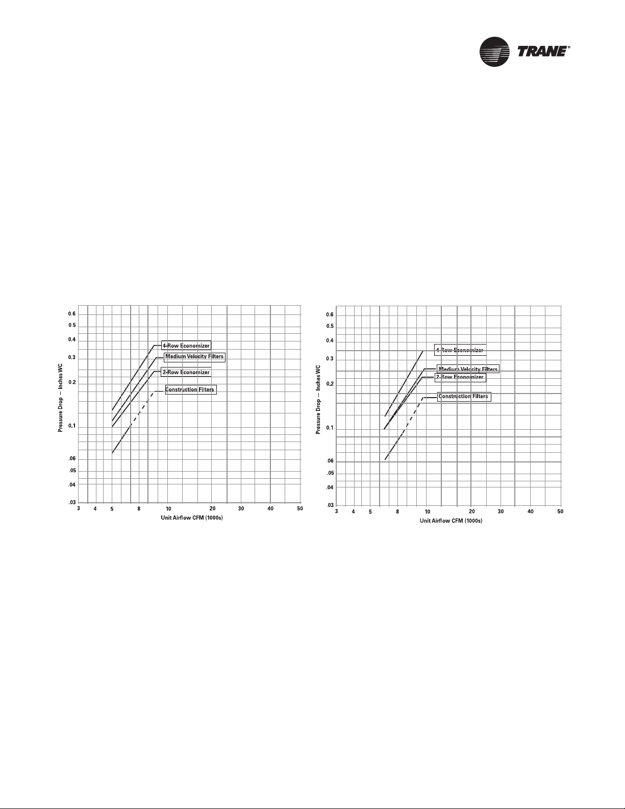
Figure 1. Airside Pressure Drop SCWF/SIWF 20, 22, 25
and SCRF/SIRF 20
Figure 2. Airside Pressure Drop SCWF/SIWF 29, 32 and
SCRF/SIRF 25, 29
Airside Pressure Drops
The dotted line on construction filters indicates cfm where face velocity exceeds manufacturer’s
recommended maximum of 300 fpm. After startup, construction filters must be replaced with
medium velocity or high velocity filters.
Air pressure drops through electric heat is 0.5 inches WC.
See “Discharge Plenum,” p. 30 for pressure drop through flexible horizontal discharge plenum and
“Heating Coils,” p. 29 for pressure drop through heating coils.
For 4-inch cartridge filters, air pressure drops must be added to the external static pressure design
point.
PKG-PRC002U-EN 27
Performance Data
Figure 3. Airside Pressure Drop SCWF/SIWF 35, 38 and
SCRF/SIRF 30, 35
Figure 4. Airside Pressure Drop SCWF/SIWF 42, 46 and
SCRF/SIRF 40
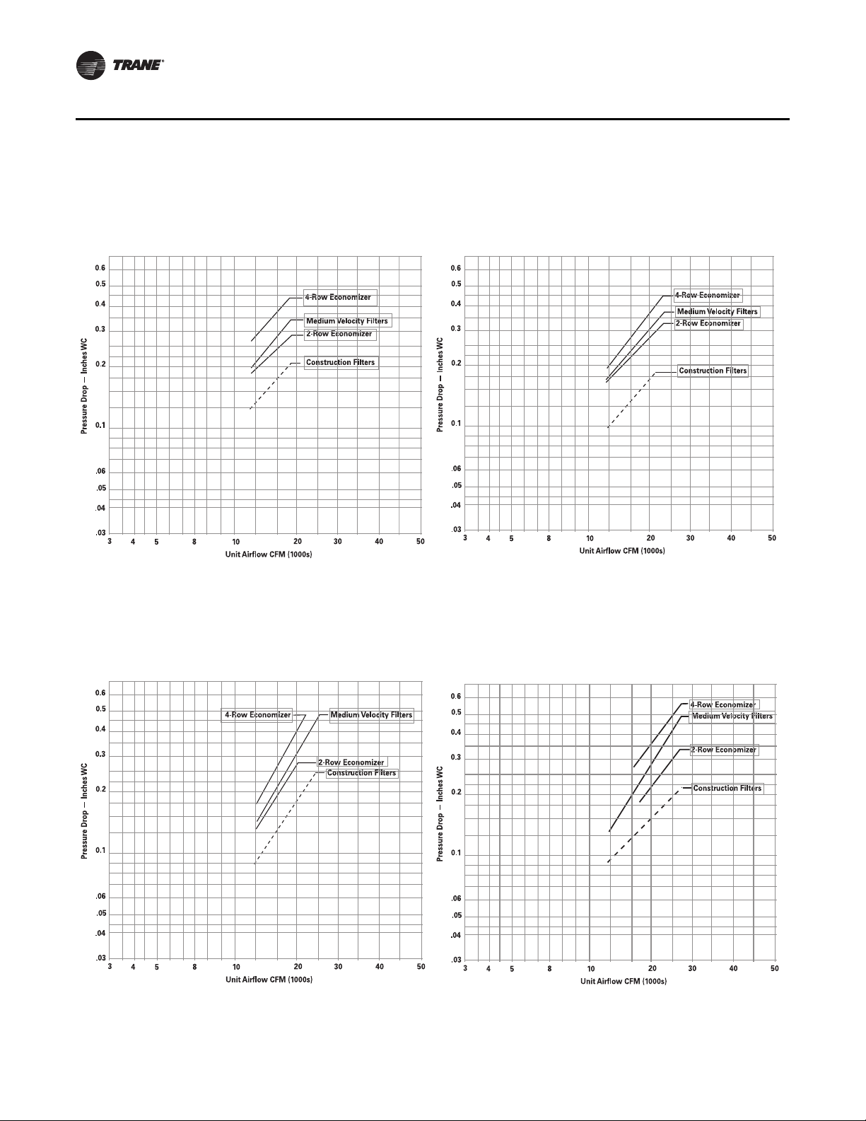
Figure 5. Airside Pressure Drop SCWF/SIWF 52, 58 and
SCRF/SIRF 50
Figure 6. Airside Pressure Drop SCWF/SIWF 65, SCWF/
SIWF 72, SCWF/SIWF 80 and SCRF/SIRF 60
28 PKG-PRC002U-EN
Performance Data
Figure 7. Airside Pressure Drop SCWF/SIWF 90-110
4 Row Economizer
2 Inch Med Eff Filter
Airflow - CFMAirflow - CFMAirflow - CFM
Air Pressure Drop - Inches of WaterAir Pressure Drop - Inches of Water
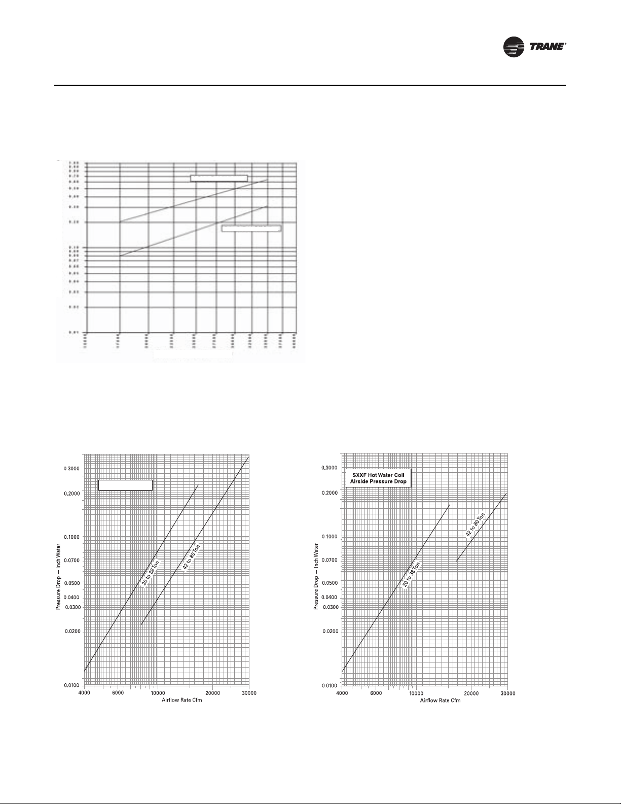
Figure 8. Airside Pressure Drop Steam Coil 20 to 80-Ton
Units
For NS Coils
Figure 9. Airside Pressure Drop Hot Water Coil 20 to 80-
Ton Units
Heating Coils
PKG-PRC002U-EN 29
Performance Data
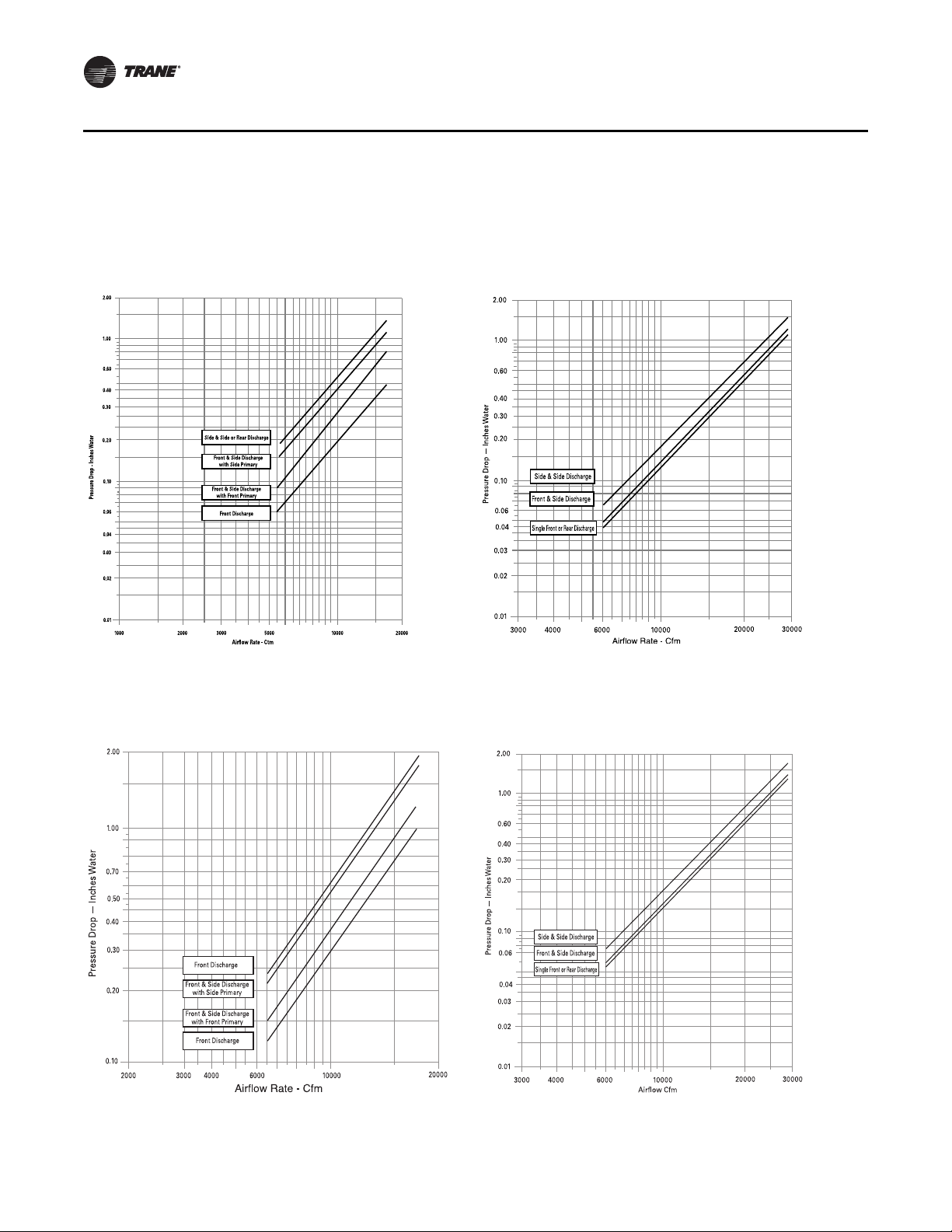
Figure 10. Airside Pressure Drop, Standard Height
Discharge Plenum 20 to 38 Ton Unit
Figure 11. Airside Pressure Drop, Standard Height
Discharge Plenum 42 to 80 Ton Unit
Figure 12. Airside Pressure Drop, Low Height Discharge
Plenum 20 to 38 Ton Unit
Figure 13. Airside Pressure Drop, Low Height Discharge
Plenum 42 to 80 Ton Unit
Discharge Plenum
30 PKG-PRC002U-EN
Loading...