


PKG-PRC002-EN
Table of contents
 Loading...
Commercial Self-Contained
IntelliPak® Signature Series
20-80 Ton Water-Cooled Air Conditioners
20-60 Ton Air-Cooled Air Conditioners
Remote Air-Cooled Condensers
December 2001 PKG-PRC002-EN
Introduction
Affordable Self-Contained Value from Trane…
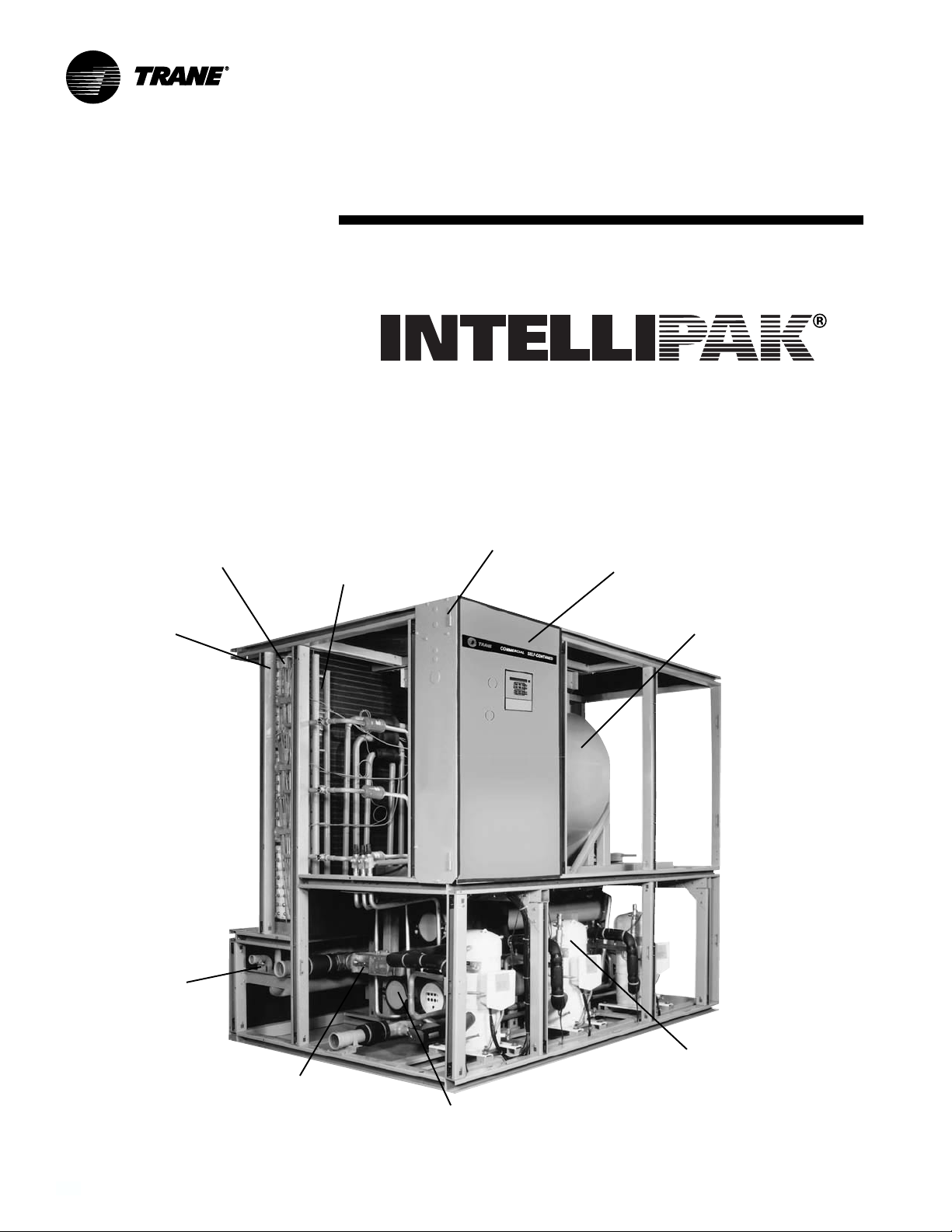
Signature Series Self-Contained Units
Trane’s advanced technology brings unmatched reliability, high performance, and affordable cost!
Hinged and removable control
Waterside economizer
(cleanable option shown)
2-inch flat filter
box inside unit
casing
Sight glasses with
ports for viewing
while unit is running
panel door for easy access
Unit mounted microprocessor
control with easy-to-read human
interface panel
Energy saving single fan
with inlet guide vanes or
variable frequency drive
Internally trapped
drain for low cost
installation
©2001 American Standard Inc.
Waterside valve
package option to
enhance system
efficiency
Two-bolt connection on cleanable
condenser for quick, easy
maintenance
®
Trane 3-D
for reliability, efficiency and
quiet operation
Scroll Compressor
PKG-PRC002-EN2
Contents
Introduction 2
Features and Benefits 4
Application Considerations 8
Selection Procedure 12
Model Number Description 14
General Data 17
Performance Data 22
Airside Pressure Drops 22
Waterside Pressure Drops 29
Water-Cooled Units 31
Air-Cooled Units 60
Heating Coils 68
Controls 69
Electrical Data 79
Dimensions and Weights 81
Mechanical Specifications 95
Options 97
PKG-PRC002-EN 3

Features and Benefits
Why consider the
Signature Series
self-contained floor-by-floor
systems?
Improved Cash Management
• Factory-installed and tested options
reduce field labor and installation risk,
while improving system reliability
• Requires less sophisticated
maintenance than built-up systems
Tenant Satisfaction
• Complete HVAC system on each floor
minimizes tenant inconvenience during
routine maintenance
• Tenants can control system after hours
to increase productivity and minimize
expense
Low First Cost
• Reduce field labor, installation time, and
cost with factory packaged controls and
piping
• Reduce installed tonnage up to 20
percent by taking advantage of building
diversity and VAV flexibility
• Flexible air discharge arrangement
matches most building configurations
Lower Installed Cost
• Single point power connection
• Single point water connection
• Factory commissioned and tested
controls
• Factory installed options
• Internally trapped drain connection
Economical Operation
• Free cooling with waterside or airside
economizer
• Energy savings with floor-by-floor
system since only units on floors
requiring cooling need to operate
• Significant annual energy consumption
reduction due to partial occupancy
after-hours, when compared to a
central chilled water system
• Simple heating alternatives include
perimeter radiation and fan-powered
VAV
• Energy savings from the integrated
water valve control using pump
unloading
Assured Acoustical Performance
• Flexible, horizontal discharge plenum
provides smooth airflow, reducing static
pressure losses for optimum acoustical
performance
• Multiple compressor design reduces
acoustical levels. Scroll compressor
design smooths gas flow for quieter
operation
Indoor Air Quality (IAQ) Features
• Sloped drain pan
• Stainless steel sloped drain pan option
• Internally trapped drain connection
• Double wall construction option
• Matt-faced fiberglass insulation
• High efficiency throwaway filter option
• Easily cleanable evaporator,
condensers, and waterside
economizers
• Filter access door allows easy removal
to encourage frequent filter changing
• Airside economizer with Traq™ damper
allows direct measurement and control
of outdoor air
Enhanced Serviceability
• Self-supporting removable panels
• Quick access service panel fasteners
• Eye level control/service center
• Refrigerant line sight glasses in view
during operation
PKG-PRC002-EN4

Features and
Benefits
Standard Features
• 20 through 80 ton industrial/commercial
water-cooled self-contained units
• 20 through 60 ton industrial/commercial
remote air-cooled self-contained units
• Fully integrated, factory-installed, and
commissioned microelectronic controls
• Unit mounted human interface panel
with a two line x 40 character clear
language (English, Spanish, or French)
display and a 16-function keypad that
includes custom, diagnostics, and
service test mode menu keys
• Improved Trane 3-D
• Compressor lead/lag
• CV or VAV system control
• Low ambient compressor lockout
adjustable control input
• FROSTAT
units
• Daytime warmup (occupied mode) on
units with heat and morning warmup
operation on all units
• Supply air static overpressurization
protection on units with inlet guide
vanes or variable frequency drives
(VFD’s)
• Supply airflow proving
• Supply air tempering control with
heating option
• Supply air heating control on VAV with
hydronic heating option
• Emergency stop input
• Mappable sensors and setpoint sources
• Occupied/unoccupied switching
• Timed override activation
• Refrigeration circuits are completely
factory piped and tested on watercooled units
• Factory piped and tested, mechanically
cleanable water-cooled condensers
• Two-bolt removable condenser
waterboxes for quick and easy cleaning
• Sloped drain pans to ensure complete
condensate removal for IAQ
• Internally trapped drain connection with
cleanout
• Internally isolated centrifugal supply fan
• 14-gauge galvanized steel framework
with easily removable painted exterior
panels of 18-gauge galvanized steel
• UL listing on standard options
• Fan belts and grease lines are easily
accessible
• Access panels and clearance provided
to clean both evaporator and waterside
economizer coil fins
™
coil frost protection on all
®
scroll compressor
• Condensing pressure control on all
variable water flow systems with valves
• Programmable water purge during
unoccupied mode
• High entering air temperature limit
• Low entering air temperature limit with
waterside economizer or hydronic heat
Optional Features
• Trane communication interface module:
ICS interface control module
• Generic BAS interface
• Comparative enthalpy control
• Ventilation override from up to five
external inputs
• Remote human interface controls up to
four units
• Fully integrated, factory-installed/
commissioned variable frequency drive
control with or without optional
integrated bypass
• Fully integrated, factory-installed and
commissioned inlet guide vanes on FC
supply fan
• Waterside economizer with factory
installed piping and controls
• Waterside modulating condensing
temperature control valves include
factory installed piping and control
wiring
• Removable cast iron headers on
cleanable waterside economizer
• Flexible horizontal discharge plenum
with or without factory cut holes
• Heating options include hot water,
steam, and electric
• Refrigerant suction discharge line
service (shut-off) valves
• Protective coatings for the unit and/or
evaporator coils
• Double wall construction
• Stainless steel sloped drain pan
• Medium efficiency throwaway filters
• Through-the-door non-fused disconnect
switch
• Trane’s air quality Traq
airside economizer mixing box
• High duct temperature thermostat
• Dual electrical power connection
reset input
•CO
2
™
damper in
FC Fans With Inlet Guide Vanes
Trane’s forward-curved fans with inlet
guide vanes pre-rotate the air in the
direction of the fan wheel. This decreases
static pressure and horsepower. The
unloading characteristics of a Trane FC
fan with inlet guide vanes results in
superior part load performance.
Variable Frequency Drives (VFD)
Variable frequency drives are factory
installed, wired, and tested to provide
supply fan motor speed modulation.
VFD’s are quieter and more efficient than
inlet quide vanes and may even be
eligible for utility rebates. The VFD’s are
available with and without a manual
integrated bypass option, controlled
through the human interface (HI) panel.
Bypass control provides full nominal
airflow control to CV zone setpoints in the
unlikely event of a drive failure by
manually placing the drive in the bypass
mode.
Field Installed Accessories
• Airside economizer control with or
without mixing box
• Programmable sensors with or without
night set back for CV and VAV systems
• ICS zone sensors used with Tracer
system for zone control
• Field installed module kits available for
field upgrade of controls
• Ultra low leak dampers for 0-100
percent modulating fresh air
economizer
®
PKG-PRC002-EN 5
Features and
Benefits
Integrated Self-Contained
Systems
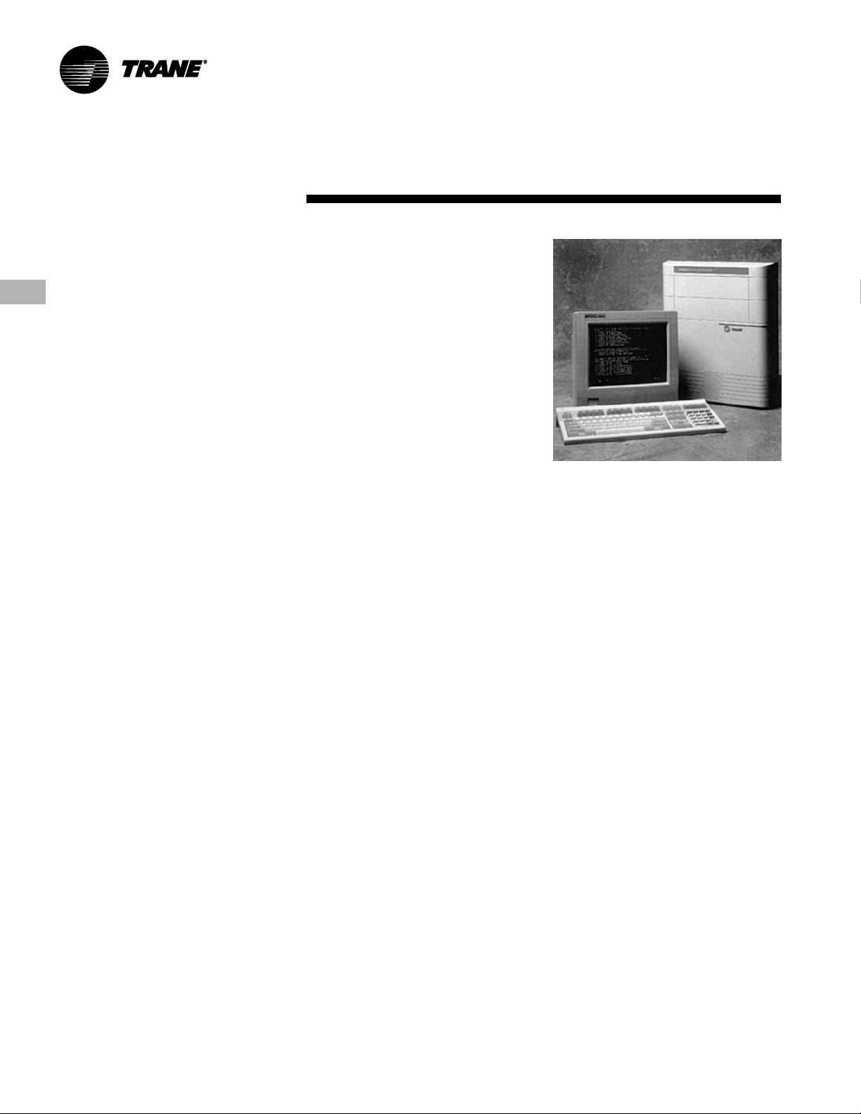
Integrated Comfort™ System (ICS)
Trane’s Integrated Comfort
(ICS) increases job control by combining
IntelliPak
®
Signature Series selfcontained units and a Tracer
management system. This integrated
system provides total building comfort
and control. Building owners and
managers not only save energy when
using ICS—they have the ability to
automate their facilities and the
convenience of a control system
interface.
Simplifying The Comfort System
Trane’s designers combined new
technology and innovation to bring you
more system capabilities and flexibility.
Our Integrated Comfort
with HVAC equipment is easy to use,
install, commission, and service.
Everything you need to know about your
self-contained VAV system is available
using Tracer
®
, Trane’s family of building
automation products. Tracer
software package that minimizes custom
programming requirements and allows
easy system setup and control using
your personal computer. Operating data
from all system components is readily
available for evaluation. You can control,
monitor, and service your facility—all
from your personal computer.
®
The IntelliPak
self-contained unit, as
part of Trane ICS, provides powerful
maintenance monitoring, control, and
reporting capabilities. Tracer
self-contained unit in the appropriate
operating mode for: system on/off, night
setback, demand limiting, setpoint
adjustment based on outside
parameters and much more. You can
monitor unit diagnostic conditions
through Tracer such as: sensor failures,
loss of supply airflow, and an inoperative
refrigerant circuit.
™
system
®
building
™
system (ICS)
®
is a
®
places the
®
IntelliPak
contained monitoring points available
using Tracer
Signature Series self-
®
• Compressor on/off status
• Ventilation status
• Condenser water flow status
• Heat status
• Supply air pressure
• Supply air temperature
• Suction temperature of each circuit
• Entering economizer water
temperature
• Zone temperature
• Entering condenser water temperature
• Supply air temperature reset signal
• Morning warmup sensor temperature
• Entering air temperature
Tracer control points for IntelliPak
®
Signature Series Self-Contained Units
• Cooling and heating setpoints
• VAV discharge air temperature
setpoints
• Supply air pressure setpoint
• Cooling and heating enable/disable
• Air economizer enable/disable
• Airside economizer minimum position
• Unit priority shutdown
Commissioning, control, efficiency, and
information…it simply all adds up to one
reliable source…Trane.
PKG-PRC002-EN6

Trane 3-D® Scroll Compressor
Simple Design with 70% Fewer Parts
Fewer parts than an equal capacity
reciprocating compressor means
significant reliability and efficiency
benefits. The single orbiting scroll
eliminates the need for pistons,
connecting rods, wrist pins, and valves.
Fewer parts lead to increased reliability.
Fewer moving parts, less rotating mass,
and less internal friction means greater
efficiency than reciprocating compressors.
Patented 3-D Scroll Compliance
Trane 3-D scroll compliance provides
important reliability and efficiency
benefits. 3-D compliance allows the
orbiting scrolls to touch in all three
dimensions, forming a completely
enclosed compression chamber that leads
to increased efficiency. In addition, 3-D
compliance means the orbiting scrolls only
touch with enough force to create a seal—
so there is no wear between the scroll
plates. The fixed and orbiting scrolls are
made of high strength cast iron—resulting
in less thermal distortion, less leakage,
and higher efficiencies. The most
outstanding feature of the scroll
compressor 3-D compliance is that
slugging will not cause failure. In a
reciprocating compressor, however, liquid
or dirt can cause serious damage.
Low Torque Variation
The 3-D scroll compressor has a very
smooth compression cycle with torque
variations that are only 30 percent of that
produced by a reciprocating compressor.
This means the scroll compressor
imposes very little stress on the motor for
greater reliability. Low torque variation
means reduced noise and vibration.
Suction Gas Cooled Motor
Compressor motor efficiency and
reliability are further optimized with this
design. Cool suction gas keeps the motor
cooler for longer life and better efficiency.
Proven Design Through Testing and
Research
With over twenty years of development
and testing, Trane 3-D scroll compressors
have undergone more than 400,000 hours
of laboratory testing and field operation.
This work combined with over 25 patents
makes Trane the worldwide leader in air
conditioning scroll compressor technology.
Features and
Benefits
One of two matched scroll plates — the
distinguishing feature of the scroll
compressor.
The Chart above illustrates low torque
variation of 3-D Scroll compressors as
compared to a reciprocating compressor.
PKG-PRC002-EN 7
Application
Self-Contained Acoustical
Recommendations
Successful acoustical results are
dependent on many system design
factors.
Following are general acoustical
recommendations. For more information,
or if there is concern about a particular
installation, contact a professional
acoustical consultant.
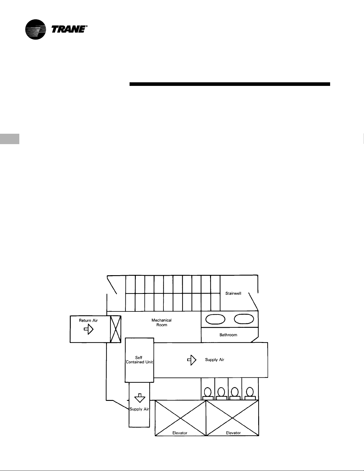
Location and Orientation of the
Mechanical Equipment Room
Locate the equipment room adjacent to
stairwells, utility rooms, electrical closets,
and rest rooms if possible (See figure
below). This minimizes the acoustic
effects and risk of workmanship or
installation errors. Place the discharge
and return air ductwork over these less
acoustically sensitive areas, using vertical
or horizontal fresh air shafts. Consult code
requirements for fresh air and smoke
purge constraints.
Considerations
Return Air Ductwork
Duct the return air into the mechanical
equipment room. Connect ductwork to
the unit if local code dictates. The return
air ductwork must have an elbow inside
the equipment room. This elbow will
reduce sound transmissions through the
return duct. Extend the ductwork from
the elbow far enough to block the “line of
sight” to the exterior of the equipment
room. Use a minimum ductwork length
of 15 feet to the equipment room
exterior. Line the duct with two-inch,
three-pound density insulation. Use
multiple, small return ducts for better
acoustical performance to the occupied
space.
Supply Air Ductwork
Insulate the supply air duct with two-inch,
three-pound density insulation. Extend
this lining at least 15 feet out from the
equipment room wall, keeping the duct
aspect ratio as small as possible.
Minimize large flat panels since they
Self-Contained
transmit sound. In addition, small aspect
ratios will minimize potential “oil canning”
of the duct due to flow turbulence.
The flexible horizontal discharge plenum
option helps avoid complicated ductwork
transitions. Ductwork turning vanes
typically improve pressure drop but
degrade acoustical performance.
Recommended Maximum Air Velocities
The maximum recommended velocity
for the discharge air duct is 2,000 fpm.
The maximum recommended velocity
for the return air duct is 1,000 fpm. Limit
air velocities below these operating
points to minimize the risk of flow
turbulence that causes regenerated
noise. Using round supply duct and static
regain allows maximum discharge air
velocities up to 3,000 fpm. Lining round
supply duct also substantially lowers
frequency noise attenuation. However,
flow regenerated noise potential
increases dramatically at air velocities
over 3000 fpm.
Equipment Room Location and Orientation
PKG-PRC002-EN8
Application
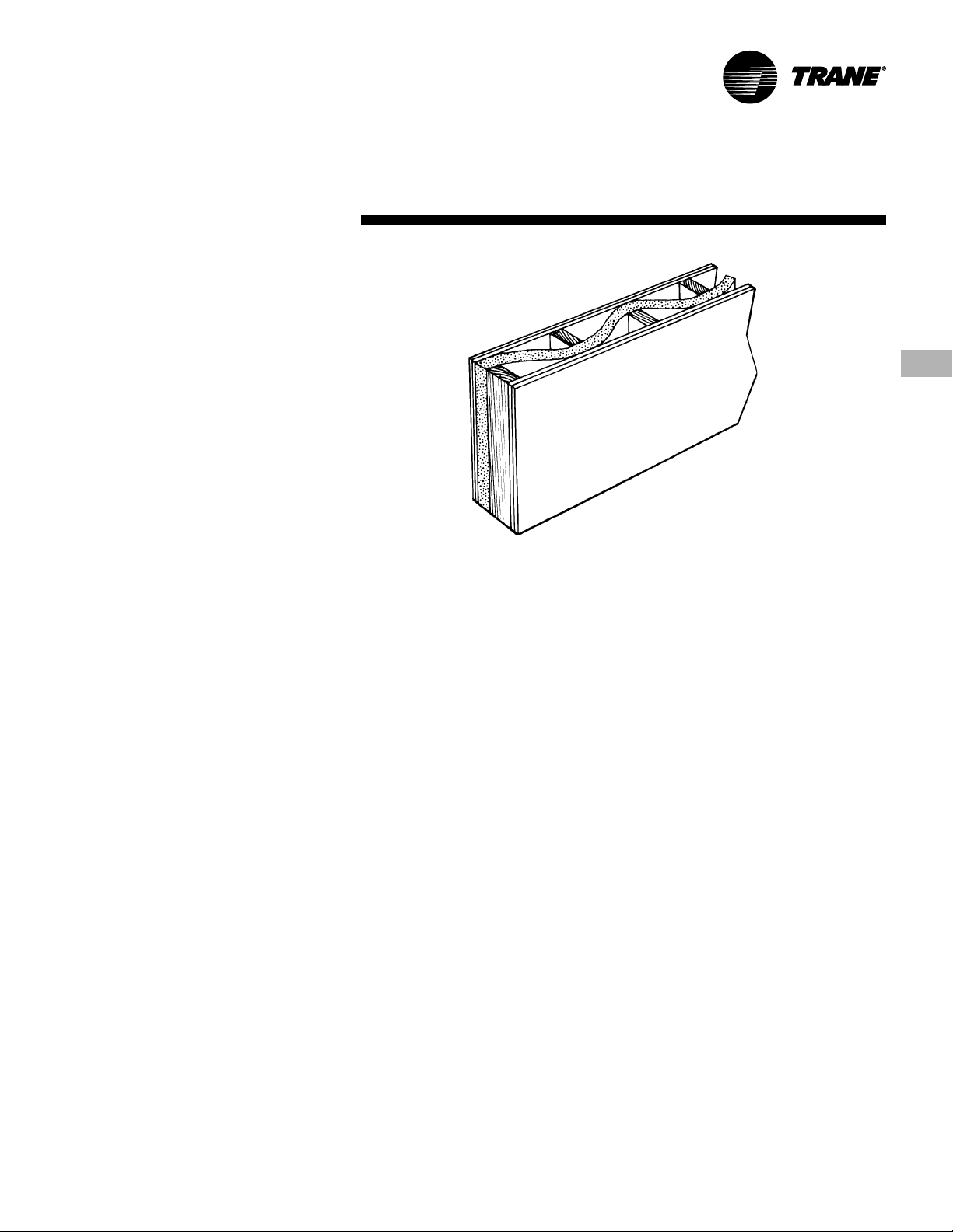
Equipment Room Construction Options
The preferred equipment room wall
construction is concrete block. If this is not
feasible then a double stud offset wall is
suggested (See figure). This removes
physical contact that would transmit
sound through the equipment room wall
to the occupied space. Interweave
fiberglass insulation between the wall
studs. Use two layers of sheetrock on
each side of the wall.
Workmanship details are critical to
acoustical performance. Seal all wall and
floor penetrations by the ductwork, water
piping, and equipment room access
doors with a flexible material such as
caulk and/or gasketing to stop noise and
air leaks.
Locate the equipment room door away
from acoustically sensitive areas like
conference rooms. The door should
swing out of the equipment room, if
possible, so that the low pressure in the
equipment room pulls the door in to help
maintain a tight seal.
Equipment Options
The flexible horizontal discharge plenum
allows multiple tested outlet options. This
minimizes the risk of acoustic and/or
pressure drop problems by avoiding
complex transitions close to the fan
discharge.
Static Pressure Versus Acoustics
Design the system to minimize the total
static pressure required from the selfcontained unit fan. Typically a change in
static pressure of only 0.5 inches can
reduce NC level by approximately 2 or 3
in the occupied space.
Isolation Recommendations
Unit
The Signature Series unit fan and
compressors are internally isolated.
Therefore, external isolation is not
required. Consult a vibration specialist
before considering external or double
vibration isolation.
Ductwork
Design duct connections to the unit using
a flexible material. Consult local codes for
approved flexible duct material to
prevent fire hazard potential.
Considerations
Double Stud Offset Wall with Interwoven Insulation
Piping Connections
Rubber isolator connectors are
recommended for condenser piping to
prevent vibration transmission to or from
the building plumbing. The Signature
Series self-contained unit is internally
isolated and does not require additional
isolation. However, ensure proper
system vibration isolation design
prevents vibration transmission from the
building plumbing to the unit. Also be sure
to properly isolate the drain line.
Condenser Water Piping
Piping Location and Arrangement
Provide at least 24 inches of clearance
between the piping and the unit for
service. Place the risers away from the
side of the unit if possible. Be sure to
allow sufficient space for valves and
unions between the piping and the selfcontained unit. Lay out condenser piping
in reverse returns to help balance the
system. This is accomplished by
equalizing the supply and return pipe
length. Multi-story buildings may use a
direct return system with balancing
valves at each floor. Install all heat
exchangers and most cooling tower
piping below the sump operating water
level to prevent overflow during unit and/
or system shut down.
Self-Contained
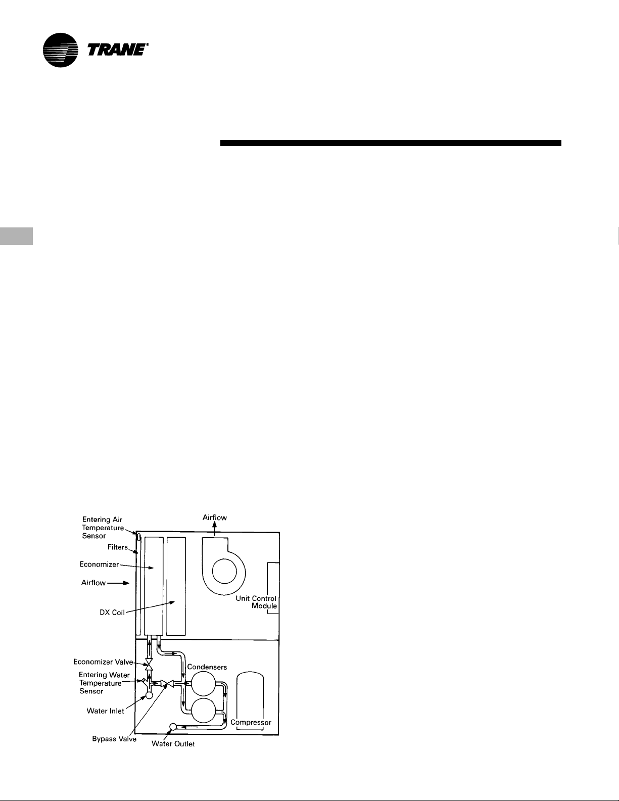
Free Cooling Opportunities
and Alternatives
Free cooling is available with either the
airside or waterside economizer options.
Waterside Economizer
The waterside economizer substantially
reduces the compressor energy
requirements because it uses the cooling
water before it enters the condensers.
Additional equipment room space is not
required since the coils are contained
within the overall unit dimensions.
Disadvantages include higher airside
pressure drop and a higher head on
condenser water pumps.
The coils may be mechanically cleanable
(optional) for ease in maintenance versus
expensive and difficult chemical cleaning
methods.
Airside Economizer
The airside economizer substantially
reduces compressor, cooling tower, and
condenser water pump energy
requirements using outside air for free
cooling. It also reduces tower make up
water needs and related water
treatment.
Disadvantages include building
requirements that locate the mechanical
room and self-contained unit toward an
exterior wall to minimize ductwork ,
building barometric control, or additional
air shafts. Also, airside economizers
require additional mechanical room
space.
PKG-PRC002-EN 9
Application
Recommended Pump Location
Locate pump downstream of the cooling
tower and upstream of the self-contained
unit. This provides smoother and more
stable unit operation.
When the tower and pump are both roof
mounted, be sure to provide the
necessary net positive suction head
pressure to prevent cavitation. Raise the
tower or submerge the pump in a sump
to provide positive suction. To prevent an
on-line pump failure, use a standby pump
to avoid a complete system shutdown.
Several partial capacity pumps or
variable speed pumps may be used.
Review the economics of these alternate
pumping options.
Strainers and Water Treatment
Water strainers are required at the unit
inlet to eliminate potential unit damage
from dirty water. Specify a water baskettype strainer to avoid an incorrect
stream strainer application. Untreated or
poorly treated water may result in
equipment damage. Consult a water
treatment specialist for treatment
recommendations.
Isolation Valves
Install isolation valves at each unit before
the strainer and after the condenser. This
allows periodic servicing of the unit or
Waterside Economizer Piping
Considerations
strainer while allowing other units in the
system to remain in operation.
Pressure Gauges
Install pressure gauges on the inlet and
outlet of the self-contained unit. Select
the gauge’s scale so that the unit design
operating point is approximately midscale.
Thermometers
Install thermometers on the condenser
water inlet and outlet lines to each unit for
system analysis. Trane Company
recommends using a thermometer
temperature range of 40 to 140 F, using
a 2 F temperature increment.
Drains
The unit condensate drain is internally
trapped to offset the pressure differential
that exists during fan operation. Install a
trapped drain in the low point of the
mechanical equipment room floor to
collect water from cleaning operations.
Condensing Pressure Control
(Water-Cooled condensers)
Often cold condensing water applications
between 35 F (1.7 C) and 54 F (12.2 C)
require a condensing pressure control
valve. Any unit with variable-flow
waterside valves can modulate water
flow to maintain a user defined
condensing temperature. However, to
Self-Contained
utilize this feature, the building water
system must be capable of operating at
reduced water flow rates through the
self-contained units. It is imperative to
install variable volume pumps or an
external bypass in the water distribution
system.
Waterside Economizer Flow Control
Units equipped with waterside
economizer control valves can be set up
for variable or constant water flow.
Use constant water flow
systems that are not capable of
unloading water supply to the unit. The
economizer and condenser valves will
operate in complement to one another to
provide continuous water flow.
Use variable water flow
flow systems that can take advantage of
pump unloading for energy savings.
Since non-cooling operation restricts
water flow during part load economizing
or condensing temperature control, it is
imperative to install variable volume
pumps or an external bypass in the water
distribution system.
Unit Operating Limits
Airflow
The minimum recommended airflow for
proper VAV system staging and
temperature control is 35 percent of
nominal design airflow. Adjusting VAV
boxes with the appropriate minimum
settings will prevent the self-contained
unit from operating in a surge condition at
airflows below this point. Continuous
operation in a surge condition can cause
fan failure. Reference General Data
Tables on pages 17-20 for minimum
airflow conditions.
Signature Series self-contained units use
fixed pitch sheaves. Adjust air balancing
by obtaining alternate fixed pitch sheave
selections from the local Trane sales
office.
Waterflow
Use 3 gpm/ton for optimum unit capacity
and efficiency. Use 2.5 or 2 gpm/ton to
reduce pump energy, cooling tower and
piping costs. However, these reduced
waterflows may impact unit capacity and
efficiency by one or two percent. Consult
General Data Tables on pages 17-20 for
unit specific waterflow ranges.
setup on water
setup with water
PKG-PRC002-EN10

Application
Air Cooled
Remote Air-Cooled Condenser
Unit Location
Unobstructed condenser airflow is
essential to maintaining capacity and
operating efficiency. When determining
unit placement, give careful
consideration to assure sufficient airflow
across the condenser coils. Avoid these
two detrimental conditions: warm air
recirculation and coil starvation.
Both warm air recirculation and coil
starvation cause reductions in unit
efficiency and capacity because of the
higher head pressure associated with
them. In more severe cases, nuisance
unit shutdowns will result from excessive
head pressures.
Considerations
Clearance
Ensure vertical condenser air discharge
is unobstructed. While it is difficult to
predict the degree of warm air
recirculation, a unit installed with a ceiling
or other obstruction above it will
experience a capacity reduction that will
reduce the maximum ambient operation
limit. Nuisance high head pressure
tripouts may also occur.
The coil inlet must also be unobstructed.
A unit installed closer than the minimum
recommended distance to a wall or other
vertical riser will experience a
combination of coil starvation and warm
air recirculation. This may result in unit
capacity and efficiency reductions, as
well as possible excessive head
pressures. Reference the service
clearance section on page 93 for
recommended lateral distances.
Condenser
Ambient Limitations
Standard ambient control allows
operation down to 45 F (7.2 C) with
cycling of condenser fans. Units with the
low ambient option are capable of
starting and operating in ambient
temperatures down to 0 F (-17.8 C).
Optional low ambient units use a
condenser fan damper arrangement that
controls condenser capacity by
modulating damper airflow in response
to saturated condenser temperature.
Maximum ambient temperature
operation of a standard condenser is 115
F (46.1 C). Operation at design ambient
above 115 F can result in excessive head
pressures. For applications above 115 F,
contact the local Trane sales office.
PKG-PRC002-EN 11

Selection Procedure
Following is a sample selection for a
standard applied water-cooled selfcontained at particular operating
conditions. Use Trane Official Product
Selection System, TOPSS
all final selections or contact your local
Trane representative.
Unit Capacities
1
Determine entering air temperature dry
bulb and wet bulb and entering water
temperature.
2
Refer to the Performance Data section
beginning on page 32 to find gross total
and sensible capacity that best meets
capacity requirements.
3
Apply the cfm correction factors from the
capacity correction factor Table
PD-1 on page 31 to determine gross total
and gross sensible capacities at desired
cfm.
4
Multiply condenser water delta T by
the total capacity cfm correction factor to
determine new condenser water delta T.
5
Using design cfm, determine static air
pressure drops for accessories from the
air pressure drop Charts PD-1 through
PD-18. Add accessory static pressure
drops to external supply and return static
air pressure drops. Use the total air
pressure drop to determine rpm and
brake horsepower requirements from the
appropriate fan curve. Note: The fan
curves include refrigerant coil and internal
cabinet static loses.
6
Calculate supply fan motor heat by using
the following equation:
Fan motor heat (MBh) = 2.8 x fan motor
brake horsepower
7
Determine net total capacity and net
sensible capacity by subtracting fan
motor heat from gross total capacity and
gross sensible capacity.
™
, for making
Self-Contained
8
Refer to Trane psychometric chart to
determine leaving air temperatures.
Waterside Economizer Capacity
1
After determining that the unit will meet
the required mechanical cooling capacity,
determine the waterside economizer
capacity by referring to the appropriate
two-row (low capacity) or four-row (high
capacity) waterside economizer capacity
tables on pages 32-58.
2
Determine entering air temperature dry
bulb and wet bulb, condenser water flow
(gpm), and economizer entering water
temperature.
3
Refer to the appropriate waterside
economizer table to find gross total and
sensible capacity and the leaving water
temperature.
4
Apply the cfm correction factor for the
waterside economizer from the
appropriate table to determine the gross
total and sensible capacities at the desired
cfm.
5
Multiply the condenser water delta T by
the total capacity cfm correction factor to
determine the new delta T.
6
Calculate supply fan motor heat by using
the following equation:
Fan motor heat (MBh) = 2.8 x fan motor
brake horsepower
7
Determine net total and sensible capacity
by subtracting fan motor heat from gross
total and sensible capacity.
8
Refer to the Trane psychometric chart to
determine leaving air temperatures.
PKG-PRC002-EN12

Selection
Selection Example
Design Conditions
Total gross capacity required =
420 MBh = 35.2 Tons
Total sensible capacity required =
315 MBh
Entering air temperature = 80/67
Entering water temperature = 85
Water flowrate = 105 gpm
Airflow = 14840 cfm at 2.5-inch
duct static pressure
Unit includes:
Inlet guide vanes
Waterside economizer
Medium velocity throwaway filters
Unit Selection
Tentatively select a 35 ton unit
Model SCWF 35.
Refer to Table PD-19 on page 43 to obtain
gross total and sensible unit capacities,
and gpm at the design conditions:
Total capacity = 419.0 MBh
Sensible capacity = 309.0 MBh
Leaving water temperature = 94.7 F
Since the design cfm is greater than the
nominal cfm, adjust the capacities and
condenser water delta T to reflect the
higher cfm:
design cfm 14840 = +6% of nom. cfm
nominal 14000
cfm
Procedure
Refer to Table PD-1 on page 31 to obtain
the capacity correction factors for +6% of
nominal cfm:
Cooling capacity multiplier = 1.009
Sensible capacity multiplier = 1.027
Multiply the capacities by the correction
factors:
419 MBh x 1.009 = 422.8 MBh
309 MBh x 1.027 = 317.3 MBh
The SCWF 35 meets the total and
sensible design requirements.
Multiply the delta T of 9.7 F, by the cooling
capacity correction factor of 1.009 to
obtain new delta T of 9.79 and add this to
the entering water temperature to obtain
the actual leaving water temperature of
94.79 F.
Determine static air pressure drops
through the accessories at the design cfm
from Chart PD-3 on page 22:
4-row waterside economizer = 0.37 in.
Medium velocity filters = 0.28 in.
add this to the 2.5 inch duct static
pressure for a total external static
pressure of 3.15 inches.
Refer to the fan curve with inlet guide
vanes, Chart PD-38 on page 43, to
determine approximate brake
horsepower and fan rpm:
Fan brake horsepower = 16 bhp
Fan rpm = 1020 rpm
Self-Contained
Determine net capacities by subtracting
fan motor heat from gross capacities:
2.8 x 16 bhp = 44.8 MBh
Net total capacity = 422.8 MBh -
44.8 MBh = 378.0 MBh
Net sensible capacity = 317.3 MBh -
44.8 MBh = 272.5 MBh
Determine waterside economizer
capacity by referring to Table PD-17 on
page 42. Use entering air of 80/67 and
entering water temperature of 55 deg F
at 105 gpm. The table provides a gross
total capacity of 282.1 MBh and gross
sensible capacity of 277.2 MBh and
60.4 deg F leaving water temperature at
nominal cfm.
Determine gross capacities at design cfm
by applying the cfm correction factors
from waterside economizer from Table
PD-1 on page 31. Use the following
correction factors:
282.1 MBh x 1.009 = 284.6 MBh
277.2 MBh x 1.027 = 284.7 MBh
Apply the cooling correction factor to
water delta T to determine new delta T of
5.45 F.
Determine net capacities by subtracting
fan motor heat for net total capacity of
239.8 MBh and net sensible capacities of
239.9 MBh.
PKG-PRC002-EN 13

Selection
Model Number
Procedure
Description
Self-Contained Model Number Description
S C W F N 20 4 2 BO A B 2 10 065 B A 1 0 1 0 A A C F A 1 1 0 T 2 0
1 2 3 4 5 6 7 8 9 10 11 12 13 14 15 16 17 18 19 20 21 22 23 24 25 26 27 28 29 30 31 32 33 34 35 36
Digit 1 - Unit Model
S = Self Contained
Digit 2 - Unit Type
C = Commercial
I = Industrial
Digit 3 - Condenser Medium
W = Water-Cooled
R = Air-Cooled
Digit 4 - Development Sequence
F = Signature Series
Digit 5 - Refrigerant Circuit Configuration
N = Independent (Water-Cooled)
M = Manifolded (30, 35, 40, 50, 60-Ton AirCooled Only)
Digit 6, 7 - Unit Nominal Capacity
20 = 20 Tons (Water or Air)
22 = 22 Tons (Water Only)
25 = 25 Tons (Water or Air)
29 = 29 Tons (Water or Air)
30 = 30 Tons (Air Only)
32 = 32 Tons (Water Only)
35 = 35 Tons (Water or Air)
38 = 38 Tons (Water Only)
40 = 40 Tons (Air Only)
42 = 42 Tons (Water Only)
46 = 46 Tons (Water Only)
50 = 50 Tons (Air Only)
52 = 52 Tons (Water Only)
58 = 58 Tons (Water Only)
60 = 60 Tons (Air Only)
65 = 65 Tons (Water Only)
72 = 72 Tons (Water Only)
80 = 80 Tons (Water Only)
Digit 8 - Unit Voltage
6 = 200 Volt/60 Hz/3 ph
4 = 460 Volt/60 Hz/3 ph
5 = 575 Volt/60 Hz/3 ph
Digit 9 - Air Volume/Temp Control
1 = IGV and Supply Air Temp Ctrl
2 = VFD and Supply Air Temp Ctrl
3 = VFD w/ Bypass and Supply
Air Temp Ctrl
4 = w/o Vol. CTRL, w/ Zone Temp Cool
5 = w/o Vol. CTRL, w/ Zone Temp
Heat/Cool
6 = w/o Vol. CTRL and Supply Air
Temp Ctrl
Digit 10, 11 - Design Sequence
BO = “B” Design
Digit 12 - Unit Construction
A = Vertical Discharge
B = Vertical Discharge with Double Wall
Digit 13 - Flexible Horizontal Discharge
Plenum Type
B = Std Plenum w/ Factory Cut Holes
C = Low Plenum w/ Factory Cut Holes
E = Std Plenum w/ Field Cut Holes
F = Low Plenum w/ Field Cut Holes
H = Std Plenum Double wall
w/ Field Cut Holes
J = Low Plenum Double wall
w/ Field Cut Holes
K = 45” Plenum w/Factory Cut Holes,
Ship Separate
L = Std Plenum w/Factory Cut Holes,
Ship Separate
M = Low Plenum w/Factory Cut Holes,
Ship Separate
N = 45” Plenum w/Field ut Holes, Ship
Separate
P = Std Plenum w/Field Cut Holes, Ship
Separate
R = Low Plenum w/Field Cut Holes, Ship
Separate
T = 45” Double Wall Plenum w/Field Cut
Holes, Ship Separate
U = Std Double Wall Plenum w/Field Cut
Holes, Ship Separate
V = Low Double Wall Plenum w/Field
Cut Holes, Ship Separate
0 = None
Digit 14 - Motor Type
1 = Std Eff. ODP Motor
2 = Premium Eff. ODP Motor
3 = Totally Enclosed Motor
Digit 15, 16 - Motor HP
05 = 5 HP Motor
07 = 7.5 HP Motor
10 = 10 HP Motor
15 = 15 HP Motor
20 = 20 HP Motor
25 = 25 HP Motor
30 = 30 HP Motor
40 = 40 HP Motor
50 = 50 HP Motor (460V & 575V Only)
Digit 17, 18, 19 - Fan RPM
040 = 400 rpm
045 = 450 rpm
050 = 500 rpm
055 = 550 rpm
060 = 600 rpm
065 = 650 rpm
070 = 700 rpm
075 = 750 rpm
080 = 800 rpm
085 = 850 rpm
090 = 900 rpm
095 = 950 rpm
100 = 1000 rpm
105 = 1050 rpm
110 = 1100 rpm
115 = 1150 rpm
120 = 1200 rpm
125 = 1250 rpm
130 = 1300 rpm
135 = 1350 rpm
140 = 1400 rpm
145 = 1450 rpm
150 = 1500 rpm
Digit 20 - Heating Type
A = Steam Coil
B = Hot Water Coil
C = Electric Heat (1 Stage)
F = Hydronic Heat Ctrl Interface
G = Elec. Heat Ctrl Interface (1 stage)
K = Steam Coil Ship Separate
L = Hot Water Coil Ship Separate
0 = Without Heat
Digit 21 - Unit Isolators
A = Isopads
B = Spring Isolators
0 = None
Digit 22 - Unit Finish
1 = Paint - Executive Beige
2 = Protective Coating
3 = Protective Coating w/ Finish Coat
Digit 23 - Future Use
0 = None
Digit 24 - Unit Connection
1 = Disconnect Switch
2 = Terminal Block
3 = Dual Point Power (2 Blocks)
PKG-PRC002-EN14

Selection
Model Number
Self-Contained Model Number Continued —
Digit 25 - Industrial Options
A = Protective Coating Evaporator Coil
B = Silver Solder
C = Stainless Steel Screws
D = A and B
E = A and C
F = B and C
G = A, B, and C
0 = None
Digit 26 - Drain Pan Type
A = Galvanized Sloped
B = Stainless Steel Sloped
Digit 27 - Waterside Economizer
A = Mechanical Clean Full Capacity (4-row)
B = Mechanical Clean Low Capacity (2-row)
C = Chemical Clean Full Capacity (4-row)
D = Chemical Clean Low Capacity (2-row)
0 = None
Digit 28 - Ventilation Control
B = Airside Econ w/ Traq
(Top O/A)
C = Airside Econ w/ Standard
Damper (Top O/A)
E = Airside Econ w/ Traq
Comparative Enthalpy
(Top O/A)
F = Airside Econ w/ Standard Damper and
Comparative Enthalpy (Top O/A)
H = None, 2-Position Damper Ventilation
Interface
J = Airside Economizer Interface
K = Airside Economizer Interface w/
Comparative Enthalpy
™
Damper
™
Damper and
Procedure
Digit 29 - Water Piping
D = Left Hand Basic Piping
F = Left Hand Intermediate Piping
K = Left Hand Basic w/ Flow Switch
M = Left Hand Intermediate
w/ Flow Switch
0 = None
Digit 30 - Condenser Tube Type
A = Standard Condenser Tubes
B = 90/10 CuNi Condenser Tubes
0 = None (Air-cooled Only)
Digit 31 - Compressor Service Valves
1 = With Service Valves
0 = None
Digit 32 - Miscellaneous System Control
1 = Timeclock
2 = Interface for Remote HI (IPCB)
3 = Dirty Filter Switch
4 = 1 and 2
5 = 1 and 3
6 = 2 and 3
7 = 1, 2 and 3
0 = None
Digit 33 - Control Interface Options
A = Generic BAS Module (GBAS)
B = Ventilation Override Module
(VOM)
C = Tracer Comm. Interface Module
(TCI)
D = Remote Human Interface (RHI)
E = GBAS and TCI
F = VOM and TCI
G = GBAS and VOM
Description
H = GBAS and RHI
J = VOM and RHI
K = TCI and RHI
L = GBAS, VOM, and TCI
M = GBAS, VOM, and RHI
N = GBAS, TCI, and RHI
P = VOM, TCI, and RHI
R = GBAS, VOM, TCI, and RHI
0 = None
Digit 34 - Agency
T = UL Agency Listing
0 = None
Digit 35 - Filter Type
1 = Construction Throwaway
2 = Med Eff. Throwaway
Digit 36 - Miscellaneous Control Option
A = Low Entering Air Temp. Protect
Device (LEATPD)
B = High Duct Temp T-Stat
(Ship Separate)
C = Plenum High Static Switch
(Ship Separate)
E = A and B
F = A and C
H = B and C
L = A, B, and C
0 = None
Self-Contained Accessory Model Number Description
P S W F S A 1 1 0 AO
1 2 3 4 5 6 7 8 9 10 11
Digit 1 - Parts/Accessories
P = Parts/Accessories
Digit 2 - Unit Model
S= Self-Contained
Digit 3 - Shipment
W = With Unit
Digit 4 - Development Sequence
F = Signature Series
G = Modular Series
Digit 5 - Sensors and Other Accessories
S = Sensors
Digit 6 - Sensors (Field Installed)
A = BAYSENS017 - Zone Temp Only (CV
and VAV)
B = BAYSENS013 - Zone Temp with
Timed Override Button (CV and VAV)
PKG-PRC002-EN 15
C = BAYSENS014 - Zone Temp with
Timed Override Button, Setpoint Dial
(CV and VAV)
E = BAYSENS008 - CV Zone Sensor
F = BAYSENS010 - CV Zone Sensor with
Indicator Lights
G = BAYSENS019 - CV Programmable
Night Setback Sensor
H = BAYSENS021 - VAV Zone Sensor
with Indicator Lights
J = BAYSENS020 - VAV Programmable
Night Setback Sensor
K = Remote Sensor Kit
L = Outside Air Temperature Sensor Kit
M = Outside Air Humidity Sensor Kit
0 = None
Digit 7 - Low Entering Air Temperature
Protection Device (Field Installed)
1 = Low Entering Air Tempeature
Protection Device
0 = None
Digit 8 - Carbon Dioxide Sensor (field
installed)
1 = Carbon Dioxide Sensor Kit
0 = None
Digit 9 - Not Used
0 = None
Digit 10, 11 - Design Sequence
A0 = A Design
Selection
Model Number
Procedure
Description
Remote Air-Cooled Condenser Model Number Description
C C R C 020 4 A AO 1 A 0 0 T
1 2 3 4 5 6 7 8 9 10 11 12 13 14 1 5 16
Digit 1 - Unit Model
C = Condenser
Digit 2 - Unit Type
C = Commercial
I = Industrial
Digit 3 - Condenser Medium
R = Remote
Digit 4 - Development Sequence
C = C
Digit 5, 6, 7 - Nominal Capacity
020 = 20 Tons
029 = 29 Tons
035 = 35 Tons
040 = 40 Tons
050 = 50 Tons
060 = 60 Tons
Digit 8 - Unit Voltage
4 = 460 Volt/60 Hz/3 ph
5 = 575 Volt/60 Hz/3 ph
6 = 200 Volt/60 Hz/3 ph
Digit 9 - Control Option
0 = No Low Ambient Damper, I-Pak.
A = No Low Ambient Damper, T-Stat.
B = Low Ambient, I-Pak.
C = Low Ambient, T-Stat.
Digit 10, 11 - Design Sequence
AO = “A” Design Sequence
Digit 12 - Unit Finish
1 = Paint (Executive Beige)
2 = Protective Coating
3 = Protective Coating with
Finish Coat
Digit 13 - Coil Options
A = Non-Coated Aluminum
C = Protective Coating Aluminum
Digit 14 - Unit Isolators
0 = None
A = Spring Isolators
B = Isopads
Digit 15 - Panels
0 = None
1 = Louvered Panels
Digit 16 - Agency Listing
0 = None
U = With UL Listing
PKG-PRC002-EN16

SCWF/SIWF
General Data
20-38 Tons
Table GD-1. SCWF/SIWF Water-Cooled Self-Contained, 20-38 Tons
Unit Size 2 0 2 2 2 5 2 9 3 2 3 5 3 8
Compressor Data
Quantity 2 2 2 1/1 1/1 3 3
NominalTon/Comp 10 10 10 15/10 15/10 10 10
Circuits 2 222233
Evaporator Coil Data
Rows 2 232434
Sq. Ft. 21.81 21.81 21.81 29.98 29.98 31.35 31.35
Sq. m (2.03) (2.03) (2.03) (2.79) (2.79) (2.91) (2.91)
FPF 144 144 144 144 144 120 144
Condenser Data
Minimum GPM w/o Econ 3 6 36 36 46 46 54 54
Minimum liters / sec. w/o Econ (2.27) (2.27) (2.27) (2.9) (2.9) (3.41) (3.41)
Minimum GPM w/ Econ 41 41 41 60 60 65 65
Minimum liters / sec. w/ Econ (2.59) (2.59) (2.59) (3.79) (3.79) (4.1) (4.1)
Maximum GPM 80 8 0 80 102 102 119 119
Maximum liters / sec. (5.05) (5.05) (5.05) (6.44) (6.44) (7.51) (7.51)
Evaporator Fan Data
Quantity 1 111111
Size (Dia. - inches) 16.5" 16.5" 16.5" 18.25" 18.25" 20" 20"
Size (Dia. - mm) (419.1) (419.1) (419.1) (463.6) (463.6) (508) (508)
Minimum HP 5 555555
Minimum kW (3.73) (3.73) (3.73) (3.73) (3.73) (3.73) (3.73)
Maximum HP 20 20 20 25 25 2 5 25
Maximum kW (14.91) (14.91) (14.91) (18.64) (18.64) (18.64) (18.64)
Minimum Design CFM 6325 6325 6500 8700 8700 9100 9880
Minimum Design liter / sec. (2985) (2985) (3068) (4106) (4106) (4295) (4663)
Maximum Design CFM 8500 9350 10625 12325 13600 14875 16150
Maximum Design liter / sec. (4012) (4413) (5014) (5817) (6418) (7020) (7622)
General Data
EER 12.9 12.6 13.4 14.1 13.6 13.3 13.4
IPLV 13.6 12.9 13.6 14.5 13.0 12.8 12.4
Refrigerant Charge - lbs. R-22
Circuit A 24 24 24 28 30 24 25
Circuit B 24 24 24 24 25 24 25
Circuit C - ----2425
Refrigerant Charge - kg R-22
Circuit A (10.9) (10.9) (10.9) (12.7) (13.6) (10.9) (11.3)
Circuit B (10.9) (10.9) (10.9) (10.9) (11.3) (10.9) (11.3)
Circuit C - ----(10.9) (11.3)
Capacity Steps - % 100/53/0 100/53/0 100/53/0 100/62/39/0 100/59/39/0 100/65/31/0 100/65/30/0
Filter Data
Quantity 8 888888
Size (inches ) 20x18x2 20x18x2 20x18x2 20x18x2 20x18x2 20x18x2 20x18x2
Size (mm) (508 X 457 X 51) (508 X 457 X 51) (508 X 457 X 51) (508 X 457 X 51) (508 X 457 X 51) (508 X 457 X 51) (508 X 457 X 51)
Quantity 4 444444
Size (inches ) 20x20x2 20x20x2 20x20x2 20x20x2 20x20x2 20x20x2 20x20x2
Size (mm) (508 X 508 X 51) (508 X 508 X 51) (508 X 508 X 51) (508 X 508 X 51) (508 X 508 X 51) (508 X 508 X 51) (508 X 508 X 51)
Notes:
1. Compressors are Trane 3D® scroll.
2. EER and IPV are rated in accordance to the ARI Standard 340/360-93. Based on 80/67 F (26.7/19.4 C) to the evaporator coil,
nominal airflow and 85-95 F (29.4/35 C) condenser water.
3. All units operate with R-22. Units ships with full operating charge.
4. Maximum cfm limits are set to prevent moisture carryover on the evaporator coil.
5. Minimum cfm limits are set to ensure stable thermal expansion valve operation at low load conditions.
6. Filter sizes are for units without hot water or steam heating coils.
PKG-PRC002-EN 17
Table GD-2. SCWF/SIWF Refrigerant Circuits,
Number of Compressors by Circuit
Unit Size
20/22/25 Ton 1- 10T 1- 10T
29/32 Ton 1- 15T 1- 10T
35/38 Ton 1- 10T 1- 10T 1- 10T
42/46 Ton 1- 15T 1- 10T 1- 10T
52/58 Ton 1- 15T 1- 15T 1- 15T
60/72 Ton 1- 15T 1- 15T 1- 15T 1- 10T
80 Ton 1- 15T 1- 15T 1- 15T 1- 15T
Note: This table depicts compressor location in unit, plan
view from left corner.
Circuit 1 2 3 4
SCWF/SIWF
General Data
42-80 Tons
Table GD-3. SCWF/SIWF Water-Cooled Self-Contained, 42-80 Tons
Unit Size 4 2 4 6 5 2 5 8 6 5 7 2 8 0
Compressor Data
Quantity 2/1 2/1 3 3 3/1 3/1 4
NominalTon/Comp 10/15 10/15 15 15 15/10 15/10 15
Circuits 3 333444
Evaporator Coil Data
Rows 3 424346
Sq. Ft. 38.57 38.57 49.09 49.09 49.09 49.09 49.09
Sq. m (3.58) (3.58) (4.56) (4.56) (4.56) (4.56) (4.56)
FPF 144 144 144 144 144 144 144
Condenser Data
Minium GPM w/o Econ 64 64 84 84 102 102 112
Minium liters / sec. w/o Econ (4.04) (4.04) (5.3) (5.3) (6.43) (6.43) (7.07)
Minimum GPM w/ Econ 64 64 84 84 102 102 112
Minium liters / sec. w/ Econ (4.04) (4.04) (5.3) (5.3) (6.43) (6.43) (7.07)
Maximum GPM 142 142 186 186 226 226 248
Maximum liters / sec. (8.96) (8.96) (11.73) (11.73) (14.26) (14.26) (15.65)
Evaporator Fan Data
Quantity 1 111111
Size (Dia. - inches) 25" 25" 25" 25" 27.5" 27.5" 27.5"
Size (Dia. - mm) (635) (635) (635) (635) (698.5) (698.5) (698.5)
Minimum HP 7.5 7. 5 1 0 10 10 10 1 0
Minimum kW (5.59) (5.59) (7.46) (7.46) (7.46) (7.46) (7.46)
Maximum HP 30 30 50 50 50 5 0 50
Maximum kW (22.37) (22.37) (37.29) (37.29) (37.29) (37.29) (37.29)
Minimum Design CFM 11200 11960 14250 15080 16900 18700 20800
Minimum Design liter / sec. (5286) (5645) (6725) (7117) (7976) (8825) (9817)
Maximum Design CFM 17850 19550 22100 24650 27625 29800 29800
Maximum Design liter / sec. (8424) (9227) (10430) (11634) (13038) (14064) (14064)
General Data
EER 14.1 14.2 13.1 13.5 13.1 13.0 13.0
IPLV 13.9 13.6 12.9 12.5 12.4 11.8 11.4
Refrigerant Charge - lbs. R-22
Circuit A 28 30 28 30 28 30 32
Circuit B 24 25 28 30 28 30 32
Circuit C 24 25 28 30 28 30 32
Circuit D - - - - 24 25 32
Refrigerant Charge - kg R-22
Circuit A (12.7) (13.6) (12.7) (13.6) (12.7) (13.6) (14.5)
Circuit B (10.9) (11.3) (12.7) (13.6) (12.7) (13.6) (14.5)
Circuit C (10.9) (11.3) (12.7) (13.6) (12.7) (13.6) (14.5)
Circuit D - - - - (10.9) (11.3) (14.5)
Capacity Steps - % 100/71/43/26/0 100/70/41/30/0 100/65/32/0 100/65/30/0 100/71/44/24/0 100/71/43/23/0 100/73/46/20/0
Filter Data
Quantity 4 444444
Size (inches ) 16x20x2 16x20x2 16x20x2 16x20x2 16x20x2 16x20x2 16x20x2
Size (mm) (406 X 508 X 51) (406 X 508 X 51) (406 X 508 X 51) (406 X 508 X 51) (406 X 508 X 51) (406 X 508 X 51) (406 X 508 X 51)
Quantity 8 888888
Size (inches ) 16x25x2 16x25x2 16x25x2 16x25x2 16x25x2 16x25x2 16x25x2
Size (mm) (406 X 635 X 51) (406 X 635 X 51) (406 X 635 X 51) (406 X 635 X 51) (406 X 635 X 51) (406 X 635 X 51) (406 X 635 X 51)
Quantity 2 222222
Size 20x20x2 20x20x2 20x20x2 20x20x2 20x20x2 20x20x2 20x20x2
Size (mm) (508 X 508 X 51) (508 X 508 X 51) (508 X 508 X 51) (508 X 508 X 51) (508 X 508 X 51) (508 X 508 X 51) (508 X 508 X 51)
Quantity 4 444444
Size 20x25x2 20x25x2 20x25x2 20x25x2 20x25x2 20x25x2 20x25x2
Size (mm) (508 X 635 X 51) (508 X 635 X 51) (508 X 635 X 51) (508 X 635 X 51) (508 X 635 X 51) (508 X 635 X 51) (508 X 635 X 51)
Notes:
1. Compressors are Trane 3D® scroll.
2. EER and IPV are rated in accordance to the ARI Standard 340/360-93. Based on 80/67 F (26.7/19.4 C) to the evaporator coil, nominal airflow and 85-95 F (29.4/35 C) condenser
water.
3. All units operate with R-22. Units ships with full operating charge.
4. Maximum cfm limits are set to prevent moisture carryover on the evaporator coil.
5. Minimum cfm limits are set to ensure stable thermal expansion valve operation at low load conditions.
6. Filter sizes are for units without hot water or steam heating coils
PKG-PRC002-EN18
SCRF/SIRF
General Data
20-60 Tons
Table GD-4. SCRF/SIRF Air-Cooled Self-Contained
Unit Size 2 0 2 5 2 9 30 35 40 50 60
Compressor Data
Quantity 2 1/1 1/1 3 3 2/1 3 4
NominalTon/Comp 10 15/10 15/10 10 10 10/15 15 15
Circuits 2 2 2 2 2 2 2 2
Evaporator Coil Data
Rows 3 2 4 3 4 4 4 6
Sq. Ft. 21.81 29.98 29.98 31.35 31.35 38.57 49.09 49.09
Sq. m (2.03) (2.79) (2.79) (2.91) (2.91) (3.58) (4.56) (4.56)
FPF 144 144 144 120 144 144 144 144
Evaporator Fan Data
Quantity 1 1 1 1 1 1 1 1
Size (Dia. - inches) 16.5" 18.25" 18.25" 20" 20" 25" 25" 27.5"
Size (Dia. - mm) (419.1) (463.6) (463.6) (508) (508) (635) (635) (698.5)
Minimum HP 5 5 5 5 5 7 .5 10 10
Minimum kW (3.73) (3.73) (3.73) (3.73) (3.73) (5.59) (7.46) (7.46)
Maximum HP 20 25 25 25 25 40 40 50
Maximum kW (14.91) (18.64) (18.64) (18.64) (18.64) (22.37) (37.29) (37.29)
Minimum Design CFM 6500 8700 8700 9100 9880 11960 15080 20800
Minimum Design liters / sec. (3068) (4106) (4106) (4295) (4663) (5645) (7117) (9817)
Maximum Design CFM 10625 12325 13600 14875 16150 19550 24650 29800
Maximum Design liters / sec. (5014) (5817) (6418) (7020) (7622) (9227) (11634) (14064)
General Data
EER 10.8 10.8 10.8 11.0 11.2 11.3 10.8 9.9
IPLV 11.8 12.1 11.4 12.8 12.6 12.5 12.0 10.0
Refrigerant Charge - lbs. R-22 57.2 66.7 72 57 57.2 66.7 7 2 72
Refrigerant Charge - kg R-22 (25.9) (30.3) (32.7) (25.9) (25.9) (30.3) (32.7) (32.7)
Capacity Steps - % 100/53/0 100/62/39/0 100/59/39/0 100/65/31/0 100/65/30/0 100/70/41/30/0 100/65/30/0 100/73/46/20/0
Filter Data
Quantity 8 8 8 8 8 4 4 4
Size (inches ) 20x18x2 20x18x2 20x18x2 20x18x2 20x18x2 16x20x2 16x20x2 16x20x2
Size (mm) (508x457x51) (508x457x51) (508x457x51) (508x457x51) (508x457x51) (406x508x51) (406x508x51) (406x508x51)
Quantity 4 4 4 4 4 8 8 8
Size (inches ) 20x20x2 20x20x2 20x20x2 20x20x2 20x20x2 16x25x2 16x25x2 16x25x2
Size (mm) (508x508x51) (508x508x51) (508x508x51) (508x508x51) (508x508x51) (406x635x51) (406x635x51) (406x635x51)
Quantity 222
Size (inches) 20x20x2 20x20x2 20x20x2
Size (mm) (508x508x51) (508x508x51) (508x508x51)
Quantity 444
Size 20x25x2 20x25x2 20x25x2
Size (mm) (508x635x51) (508x635x51) (508x635x51)
CCRC/CIRC Unit Match 20 29 29 35 35 40 50 60
Notes:
1. Compressors are Trane 3D® scroll.
2. EER and IPLV are rated in accordance to the ARI Standard 340/360-93. Based on 80/67 F (26.7/19.4 C) to the evaporator coil, nominal airflow and 95 F (35 C) ambient.
3. All units operate with R-22. Units ships with a dry nitrogen holding charge.
4. Maximum cfm limits are set to prevent moisture carryover on the evaporator coil.
5. Minimum cfm limits are set to ensure stable thermal expansion valve operation at low load conditions.
6. Filter sizes are for units without hot water or steam heating coils
Table GD-5. SCRF/SIRF Refrigerant Circuits,
Number of Compressors by Circuit
Unit Size
20 Ton 1-10T 1- 10T
25/29 Ton 1-15T 1-10T
30/35 Ton 2-10T 1-10T
40 Ton 1- 10T, 1- 15T 1-15T
50 Ton 2-15T 1-15T
60 Ton 2-15T 2-15T
Note: This table depicts compressor location in unit, plan
view from left corner
PKG-PRC002-EN 19
Circuit 1 2
General Data
CCRC/CIRC
Table GD-6. CCRC/CIRC Remote Air-Cooled Condenser
Unit Size 2 0 2 9 3 5 4 0 5 0 6 0
Gross Heat Rejection (MBH) 493 53 8 640 725 1040 1122
Gross Heat Rejection (kW) (144.5) (157.7) (187.6) (212.5) (304.8) (328.8)
Condenser Fan Data
Number/Type 4/Prop 4/Prop 6/Prop 6/Prop 8/Prop 8/Prop
Size (inches) 26 26 26 26 26 26
Size (mm) (660.4) (660.4) (660.4) (660.4) (660.4) (660.4)
Fan Drive Direct Direct Direct Direct Direct Direct
No. of Motors/HP ea. 4/1 4/1 6/1 6/1 8/1 8/1
Nominal CFM 18,800 21,200 35,600 39,800 46,200 56,400
Nominal (liters / sec) (8873) (10005) (16801) (18784) (21804) (26618)
Condenser Coil Data
Circuit 1 Size (in.) 1/46x71 1/64x71 2/46x71 2/46x71 2/64x71 2/64x71
Circuit 1 Size (mm) (1/1168x1803) (1/1626x1803) (2/1168x1803) (2/1168x1803) (2/1626x1803) (2/1626x1803)
Circuit 2 No./Size (in.) 1/46x71 1/46x71 1/46x71 1/64x71 1/64x71 2/64x71
Circuit 2 No./Size (mm) (1/1168x1803) (1/1168x1803) (1/1168x1803) (1/1626x1803) (1/1626x1803) (2/1626x1803)
Face Area (sq. ft.) 45.4 54.2 68 76.9 94.7 126.2
Face Area (sq.m) (4.2) (5) (6.3) (7.1) (8.8) (11.7)
Rows/fpf 4/144 4/144 4/144 4/144 4/144 4/144
Ambient Temperature Operating Range
Standard Ambient (F) 50-115 50-115 50-115 50-115 50-115 50-115
Standard Ambient (C) (10 - 46.1) (10 - 46.1) (10 - 46.1) (10 - 46.1) (10 - 46.1) (10 - 46.1)
Low Ambient Option (F) 0-115 0-115 0-115 0-115 0-115 0-115
Low Ambient Option (C) (-17.8 - 46.1) (-17.8 - 46.1) (-17.8 - 46.1) (-17.8 - 46.1) (-17.8 - 46.1) (-17.8 - 46.1)
Notes:
1. Gross Heat Rejection is at a 20 F (-6.7 C) ITD (Initial Temperature Difference) between condensing temperature and ambient air entering condenser (includes the effect of
subcooling).
2. Operating charge is for entire unit, including 100 feet of interconnecting piping.
3. At conditions of 95 F (35 C), condenser is 95 percent full.
Table GD-7. SCRF/SIRF Air–Cooled Self–Contained and CCRC/CIRC Remote Air-Cooled Condenser
Unit Size 2 0 2 9 3 5 4 0 5 0 6 0
Refrigerant Circuit General Data
No. of Refrigerant Circuits 2 2 2 2 2 2
Operating Charge - lbs. R-22 36/36 58/36 72/36 94/36 115/58 115/115
Operating Charge - kg R-22 (16.3/16.3) (26.3/16.3) (32.7/16.3) (42.6/16.3) (52.2/26.3) (52.2/56.7)
Cond. Storage Cap. - lbs. R-22 44/44 61/44 88/44 105/44 122/122 122/122
Cond. Storage Cap. - kg R-22 (20/20) (27.7/20) (39.9/20) (47.6/20) (55.3/55.3) (55.3/55.3)
Notes:
1. Gross heat rejection is at a 20 F (-6.7 C) ITD (initial temperature difference) between condensing temperature and ambient air entering condenser (includes the effect of
subcooling).
2. Operating charge is for entire system, which includes the air–cooled self–contained, remote air–cooled condenser, and 25 feet of interconnecting refrigerant piping.
3. At conditions of 95 F (35 C), condenser storage capacity is 95% full.
4. To determine the correct amount of refrigerant needed for a particuliar application, reference the
Trane Reciprocating Refrigeration Manual
.
PKG-PRC002-EN20

General Data
Heating Coil
Table GD-7. Self-Contained Heating Coil
Unit Size SCWF 20 - 38 SCWF 42 - 80 SCRF 20 - 35 SCRF 40 - 60
Steam Coil
Coil Type NS NS NS NS
Rows Rows 1 1 1 1
No./Size (inches) ((2) 24x58) ((2) 30x81) ((2) 24x58) ((2) 30x81)
No./Size (mm) ((2) 609.6x1473.2) ((2) 762x2057.4) ((2) 609.6x1473.2) ((2) 762x2057.4)
FPF 42 42 42 42
Hot Water Coil
Coil Type WC WC WC WC
Rows 1 1 1 1
No./Size (inches) (2) 24x58 (2) 30x81 (2) 24x58 (2) 30x81
No./Size (mm) ((2) 609.6x1473.2) ((2) 762x2057.4) ((2) 609.6x1473.2) ((2) 762x2057.4)
FPF 80 80 80 80
Filter Data
Quantity 4 4 4 4
Size (inches) 20x18x2 16x20x2 20x18x2 16x20x2
Size (mm) (508x457x51) (406x508x51) (508x457x51) (406x508x51)
Quantity 8 8 8 8
Size (inches) 20x20x2 16x25x2 20x20x2 16x25x2
Size (mm) (508x508x51) (406x635x51) (508x508x51) (406x635x51)
Quantity 2 2
Size (inches) 20x20x2 20x20x2
Size (mm) (508x508x51) (508x508x51)
Quantity 4 4
Size (inches) 20x25x2 20x25x2
Size (mm) (508x635x51) (508x635x51)
Notes:
1. Hot water and steam heating coils have Prima-Flo® fins without turbulators.
2. For coil capacites, use TOPSS™ (Trane Official Product Selection Program).
3. Full capacity coils consist of two coils stacked and piped in parallel.
PKG-PRC002-EN 21
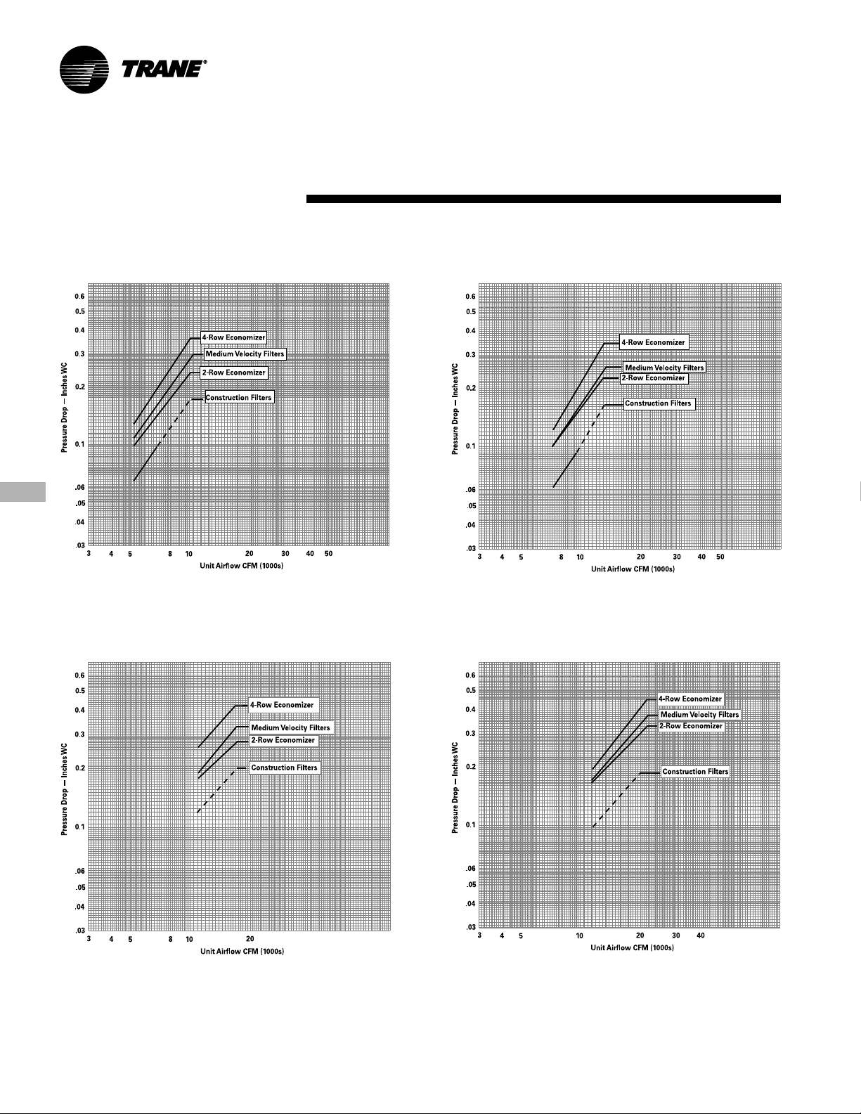
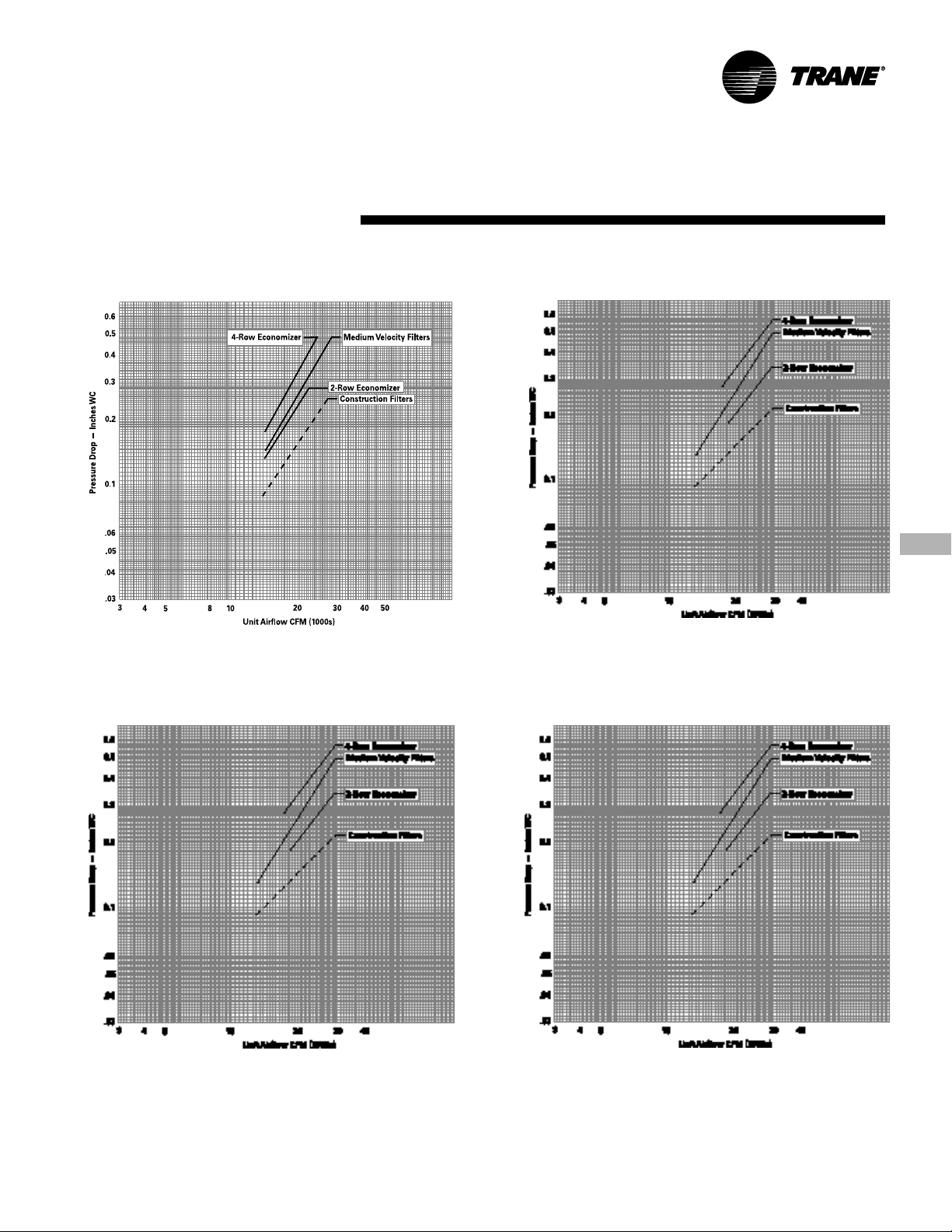
Performance Airside Pressure
Data Drops
Chart PD-1. Airside Pressure Drop
SCWF/SIWF 20, 22, 25 and SCRF/SIRF 20
Chart PD-3. Airside Pressure Drop
SCWF/SIWF 35, 38 and SCRF/SIRF 30, 35
Chart PD-2. Airside Pressure Drop
SCWF/SIWF 29, 32 and SCRF/SIRF 25, 29
Chart PD-4. Airside Pressure Drop
SCWF/SIWF 42, 46 and SCRF/SIRF 40
Notes:
1. Dotted line on construction filters indicates cfm where face velocity exceeds manufacturer’s recommended maximum of 300 fpm. After startup, construction filters must be
replaced with medium velocity or high velocity filters.
2. Air pressure drop through electric heat is 0.5 inches WC.
3. Refer to Page 25-26 for pressure drop through flexible horizontal discharge plenum.
4. Refer to Page 24 for pressure drop through heating coils.
PKG-PRC002-EN22
Performance Airside Pressure
Data Drops
Chart PD-5. Airside Pressure Drop
SCWF/SIWF 52, 58 and SCRF/SIRF 50
Chart PD-7. Airside Pressure Drop
SCWF/SIWF 72
Chart PD-6. Airside Pressure Drop
SCWF/SIWF 65
Chart PD-8. Airside Pressure Drop
SCWF/SIWF 80 and SCRF/SIRF 60
Notes:
1. Dotted line on construction filters indicates cfm where face velocity exceeds manufacturer’s recommended maximum of 300 fpm. After startup, construction filters must be
replaced with medium velocity or high velocity filters.
2. Air pressure drop through electric heat is 0.5 inches WC.
3. Refer to Page 25-26 for pressure drop through flexible horizontal discharge plenum.
4. Refer to Page 24 for pressure drop through heating coils.
PKG-PRC002-EN 23
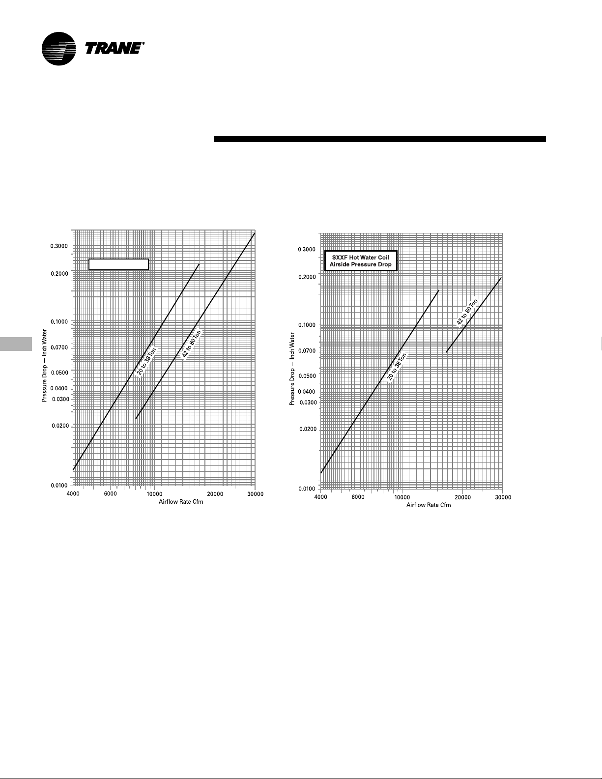
Heating Coils
Chart PD-9. Airside Pressure Drop
Steam Coil
20 to 80-Ton Units
For NS Coils
Performance Airside Pressure
Data Drops
Chart PD-10. Airside Pressure Drop
Hot Water Coil
20 to 80-Ton Units
PKG-PRC002-EN24
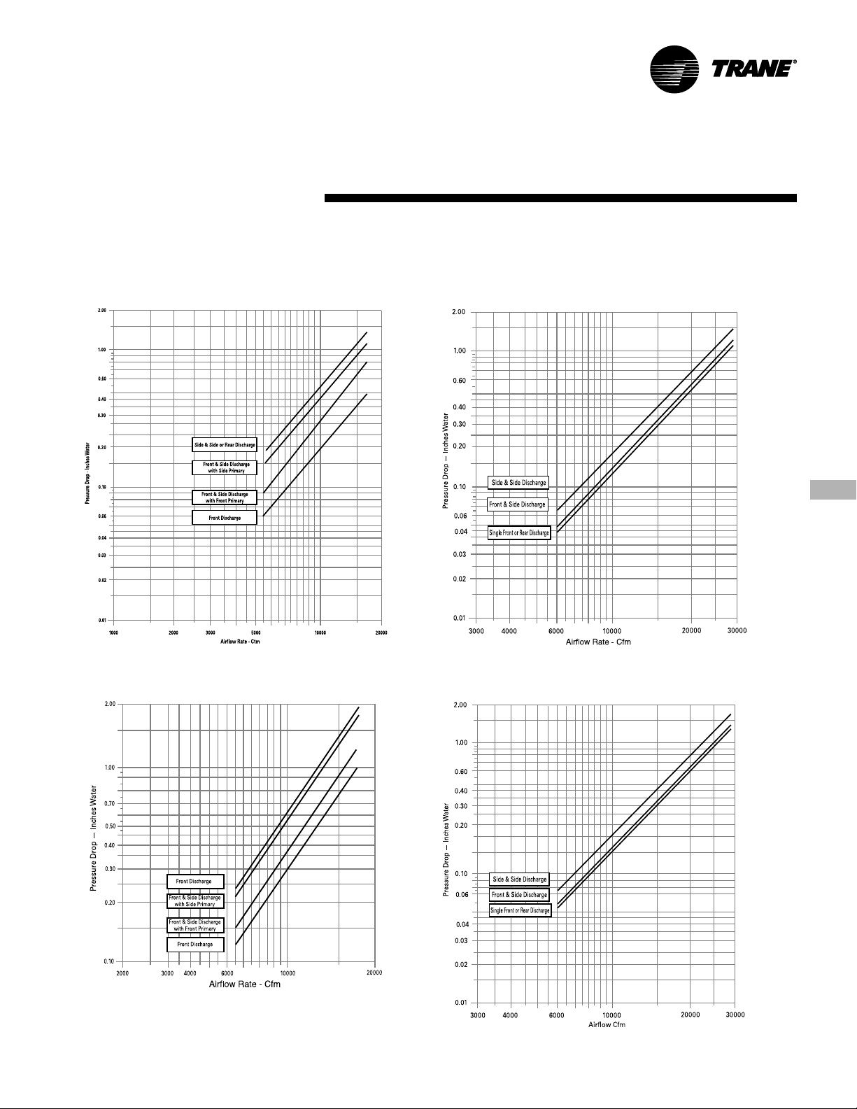
Discharge Plenum
Chart PD-10. Airside Pressure Drop,
Standard Height Discharge Plenum
20 to 38 Ton Unit
Performance Airside Pressure
Data Drops
Chart PD-11. Airside Pressure Drop
Standard Height Discharge Plenum
42 to 80 Ton Unit
Chart PD-12. Airside Pressure Drop
Low Height Discharge Plenum
20 to 38 Ton Unit
Note:
“Primary” refers to the side where the static pressure drop was measured. This value
must be added to the unit external static pressure for proper fan horsepower
determination.
Chart PD-13. Airside Pressure Drop
Low Height Discharge Plenum
42 to 80 Ton Unit
PKG-PRC002-EN 25

Performance Airside Pressure
Data Drops
Discharge Plenum
Chart PD-14. Airside Pressure Drop
Extended Height Discharge Plenum
20 to 38-Ton Unit
Chart PD-15. Airside Pressure Drop
Extended Height Discharge Plenum
42 to 80-Ton Unit
PKG-PRC002-EN26
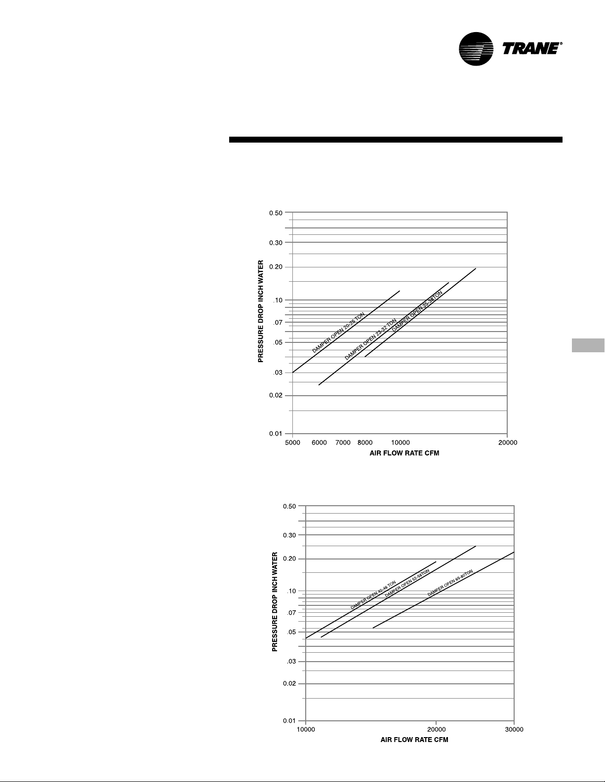
Performance Airside Pressure
Data Drops
Airside Economizer with
Standard Damper
Chart PD-16. Airside Pressure Drop
Airside Economizer with Standard Damper
20 to 38-Ton Unit
Chart PD-17. Airside Pressure Drop
Airside Economizer with Standard Damper
42 to 80-Ton Unit
PKG-PRC002-EN 27

Performance Airside Pressure
Data Drops
Airside Economizer with
Traq™ Damper
Chart PD-18. Airside Pressure Drop
Airside Economizer with Traq™ Damper
Air Flow Rate CFM
PKG-PRC002-EN28
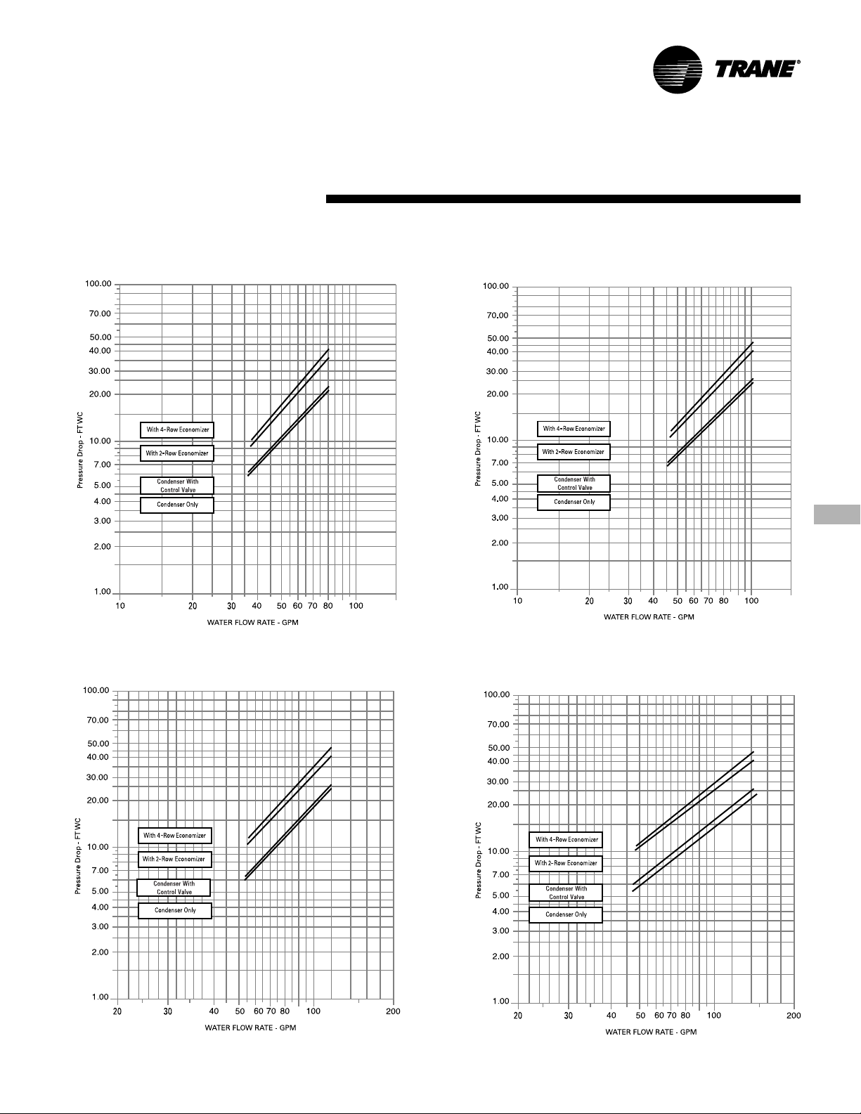
Performance Waterside
Data Pressure Drop
Chart PD-19. Waterside Pressure Drop
SCWF/SIWF 20, 22, 25
Chart PD-21. Waterside Pressure Drop
SCWF/SIWF 35, 38
Chart PD-20. Waterside Pressure Drop
SCWF/SIWF 29, 32
Chart PD-22. Waterside Pressure Drop
SCWF/SIWF 42, 46
Note: Each curve provides total water pressure drop through the entire unit including all accessories and internal valves and piping. Do not add curves together.
PKG-PRC002-EN 29
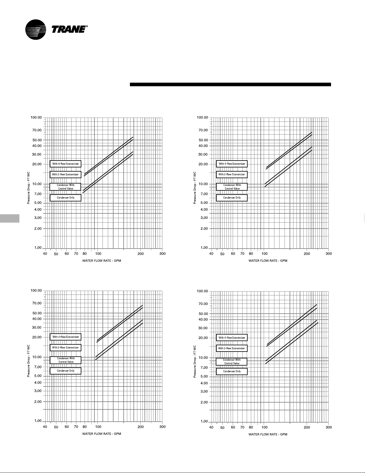
Performance Waterside
Data Pressure Drop
Chart PD-23. Waterside Pressure Drop
SCWF/SIWF 52, 58
Chart PD-25. Waterside Pressure Drop
SCWF/SIWF 72
Chart PD-24. Waterside Pressure Drop
SCWF/SIWF 65
Chart PD-26. Waterside Pressure Drop
SCWF/SIWF 80
Note: Each curve provides total water pressure drop through the entire unit including all accessories and internal valves and piping. Do not add curves together.
PKG-PRC002-EN30
Loading...