


TCD330B
Trane TCD330B, TCD360B, TCD420B, TCD480B, TCD600B Installation And Maintenance Manual
...
Installation, Operation,
and Maintenance
Voyager™ Commercial
27.5 to 50 Ton 60 Hz
22.9 to 41.7 Ton 50 Hz
CV, VAV, or SZ VAV Rooftop Air Conditioners
with ReliaTel™ Controls, R-410A Refrigerant
Model Numbers
“B” and later design sequence
TC*, TE*, YC*330B, 360B, 420B, 480B, 600B (60 Hz/3 phase)
TC*, TE*, YC*275B, 305B, 350B, 400B, 500B (50 Hz/3 phase)
Only qualified personnel should install and service the equipment. The installation, starting up, and
servicing of heating, ventilating, and air-conditioning equipment can be hazardous and requires specific
knowledge and training. Improperly installed, adjusted or altered equipment by an unqualified person could
result in death or serious injury. When working on the equipment, observe all precautions in the literature
and on the tags, stickers, and labels that are attached to the equipment.
August 2012 RT-SVX34F-EN
SAFETY WARNING
Warnings, Cautions and Notices
Warnings, Cautions and Notices. Note that warnings,
cautions and notices appear at appropriate intervals
throughout this manual. Warnings are provided to alert
installing contractors to potential hazards that could result
in personal injury or death. Cautions are designed to alert
personnel to hazardous situations that could result in
personal injury, while notices indicate a situation that could
result in equipment or property-damage-only accidents.
Your personal safety and the proper operation of this
machine depend upon the strict observance of these
precautions.
ATT EN TI ON : Warnings, Cautions and Notices appear at
appropriate sections throughout this literature. Read these
carefully:
WARNING
CAUTIONs
NOTICE:
Indicates a potentially hazardous
situation which, if not avoided, could
result in death or serious injury.
Indicates a potentially hazardous
situation which, if not avoided, could
result in minor or moderate injury. It
could also be used to alert against
unsafe practices.
Indicates a situation that could result in
equipment or property-damage only
Personal Protective Equipment (PPE)
Required!
Installing/servicing this unit could result in exposure to
electrical, mechanical and chemical hazards.
• Before installing/servicing this unit, technicians
MUST put on all Personal Protective Equipment (PPE)
recommended for the work being undertaken.
ALWAYS refer to appropriate MSDS sheets and OSHA
guidelines for proper PPE.
• When working with or around hazardous chemicals,
ALWAYS refer to the appropriate MSDS sheets and
OSHA guidelines for information on allowable
personal exposure levels, proper respiratory
protection and handling recommendations.
• If there is a risk of arc or flash, technicians MUST put
on all Personal Protective Equipment (PPE) in
accordance with NFPA 70E or other country-specific
requirements for arc flash protection, PRIOR to
servicing the unit.
Failure to follow recommendations could result in death
or serious injury.
WARNI NG
Important
Environmental Concerns!
Scientific research has shown that certain man-made
chemicals can affect the earth’s naturally occurring
stratospheric ozone layer when released to the
atmosphere. In particular, several of the identified
chemicals that may affect the ozone layer are refrigerants
that contain Chlorine, Fluorine and Carbon (CFCs) and
those containing Hydrogen, Chlorine, Fluorine and Carbon
(HCFCs). Not all refrigerants containing these compounds
have the same potential impact to the environment. Trane
advocates the responsible handling of all refrigerantsincluding industry replacements for CFCs such as HCFCs
and HFCs.
Responsible Refrigerant Practices!
Trane believes that responsible refrigerant practices are
important to the environment, our customers, and the air
conditioning industry. All technicians who handle
refrigerants must be certified. The Federal Clean Air Act
(Section 608) sets forth the requirements for handling,
reclaiming, recovering and recycling of certain refrigerants
and the equipment that is used in these service procedures.
In addition, some states or municipalities may have
additional requirements that must also be adhered to for
responsible management of refrigerants. Know the
applicable laws and follow them.
WARNI NG
Proper Field Wiring and Grounding
Required!
All field wiring MUST be performed by qualified
personnel. Improperly installed and grounded field
wiring poses FIRE and ELECTROCUTION hazards. To
avoid these hazards, you MUST follow requirements for
field wiring installation and grounding as described in
NEC and your local/state electrical codes. Failure to
follow code could result in death or serious injury.
Overview of Manual
One copy of the appropriate service literature ships inside
the control panel of each unit. The procedures discussed in
this manual should only be performed by qualified,
experienced HVAC technicians.
Note: Do not release refrigerant to the atmosphere! If
adding or removing refrigerant is required, the
service technician must comply with all federal,
state, and local laws.
This booklet describes the proper installation, startup,
operation, and maintenance procedures for TC_, TE_, and
YC_22.9 to 50 Ton CV (Constant Volume), VAV (Variable Air
Volume), and SZ VAV (Single Zone Variable Air Volume)
applications. Refer to the table of contents for a listing of
specific topics. Refer to “Diagnostics,” p. 104 for
troubleshooting information.
© 2012 Trane All rights reserved RT-SVX34F-EN
By carefully reviewing the information within this manual
and following the instructions, the risk of improper
operation and/or component damage will be minimized.
It is important that periodic maintenance be performed to
help assure trouble free operation. A maintenance
schedule is provided at the end of this manual. Should
equipment failure occur, contact a qualified service
organization with qualified, experienced HVAC technicians
to properly diagnose and repair this equipment.
Revision History
RT-SVX34F-EN (10 August 2012)
• Motors with Internal Shaft Grounding Ring
• Updated Model Number Description, Installation
Electrical, Unit Wiring Diagrams
Warnings, Cautions and Notices
60 Hz units with standard options are certified by
Underwriters Laboratory.
RT-SVX34F-EN 3

Table of Contents
Model Number Description . . . . . . . . . . . . . . . 7
60 Hz Description . . . . . . . . . . . . . . . . . . . . . . 7
50 Hz Description . . . . . . . . . . . . . . . . . . . . . . 9
General Information . . . . . . . . . . . . . . . . . . . . 11
Commonly Used Acronyms and Abbrevia-
tions . . . . . . . . . . . . . . . . . . . . . . . . . . . . . . 11
About the Unit . . . . . . . . . . . . . . . . . . . . . 11
Precautionary Measures . . . . . . . . . . . . . 12
Unit Inspection . . . . . . . . . . . . . . . . . . . . . 12
Storage . . . . . . . . . . . . . . . . . . . . . . . . . . . 12
Unit Dimensions and Weights . . . . . . . . . . . 13
Recommended Clearances . . . . . . . . . . . . . 13
Roof Curb and Ductwork . . . . . . . . . . . . . . . 13
Horizontal Ductwork . . . . . . . . . . . . . . . . . 13
Unit Rigging and Placement . . . . . . . . . . . 19
Installation General Requirements . . . . . . . 21
Condensate Drain Connection . . . . . . . . . . 21
O/A Sensor & Tubing Installation . . . . . . . 21
Units with Statitrac™ . . . . . . . . . . . . . . . . . 21
Installation Electrical . . . . . . . . . . . . . . . . . . . . 23
Disconnect Switch External Handle (Factory
Mounted Option)
. . . . . . . . . . . . . . . . . . . . . 23
Main Power Wiring . . . . . . . . . . . . . . . . . . . 23
Through-the-Base Electrical (Optional Acces-
sory) . . . . . . . . . . . . . . . . . . . . . . . . . . . . . . 24
Electrical Wire Sizing and Protection Device
Equations
Low Voltage Wiring . . . . . . . . . . . . . . . . . 28
Control Power Transformer . . . . . . . . . . . 28
Field Installed AC Control Wiring . . . . . . 28
Field Installed DC Control Wiring . . . . . . 29
. . . . . . . . . . . . . . . . . . . . . . . . . . . . 27
Remote Panels and Sensors . . . . . . . . . . . 32
Constant Volume and Single Zone VAV Con-
trol Options . . . . . . . . . . . . . . . . . . . . . . . . 32
Variable Air Volume (non-SZ VAV) Control
Options . . . . . . . . . . . . . . . . . . . . . . . . . . . 32
Installation Piping . . . . . . . . . . . . . . . . . . . . . . 36
General Requirements . . . . . . . . . . . . . . . . 36
Connecting the Gas Supply Line to the Fur-
nace Gas Train . . . . . . . . . . . . . . . . . . . . . 36
Startup . . . . . . . . . . . . . . . . . . . . . . . . . . . . . . . . .38
Unit Control Modules . . . . . . . . . . . . . . . . . .38
RTRM - ReliaTel Refrigeration Module . . .38
ECA - Economizer Actuator (Optional) . . .38
PEA - Power Exhaust Actuator (Optional) 38
RTAM - ReliaTel Air Handler Module (Stan-
dard with Traditional VAV) . . . . . . . . . . . .38
Conventional Thermostat Connections
(Available Only with CV) . . . . . . . . . . . . . .39
TCI - Trane Communication Interface (Option-
al) . . . . . . . . . . . . . . . . . . . . . . . . . . . . . . . . .39
LCI - LonTalk® Communication Interface (Op-
tional) . . . . . . . . . . . . . . . . . . . . . . . . . . . . .40
BCI - BACnet® Communication Interface (Op-
tional) . . . . . . . . . . . . . . . . . . . . . . . . . . . . .40
Manual Motor Protectors (380V Through
575V Only) . . . . . . . . . . . . . . . . . . . . . . . . .40
System Operation . . . . . . . . . . . . . . . . . . . . .40
Economizer Operation with a Conventional
Thermostat (CV Only) . . . . . . . . . . . . . . . .40
Microelectronic Control Features . . . . . . .40
Economizer Operation with CV Controls .41
Modulating Power Exhaust . . . . . . . . . . . .41
Mechanical Cooling without an Economizer
(CV and SZ VAV) . . . . . . . . . . . . . . . . . . . . 42
Zone Temperature - Occupied Cooling (CV
and SZ VAV) . . . . . . . . . . . . . . . . . . . . . . . .42
Zone Temperature - Occupied Heating (CV
and SZ VAV) . . . . . . . . . . . . . . . . . . . . . . . .42
Supply Fan (CV and SZ VAV) . . . . . . . . . .42
Supply Air Tempering (CV and SZ VAV) .42
Variable Air Volume Applications (Single
Zone VAV)
Supply Fan Output Control . . . . . . . . . . . .43
Minimum Supply Fan Output . . . . . . . . . .43
Supply Fan Mode Operation . . . . . . . . . . .43
Setpoint Arbitration . . . . . . . . . . . . . . . . . .44
Ventilation Control . . . . . . . . . . . . . . . . . . .44
Space Pressure Control . . . . . . . . . . . . . . .46
Supply Air Temperature Control - Heating
and Cooling . . . . . . . . . . . . . . . . . . . . . . . . 46
. . . . . . . . . . . . . . . . . . . . . . . . . . . .43
4 RT-SVX34F-EN

Table of Contents
Variable Air Volume Applications (Traditional
VAV)
. . . . . . . . . . . . . . . . . . . . . . . . . . . . . . . . 47
Supply Air Temperature Control - Occupied
Cooling and Heating . . . . . . . . . . . . . . . . 47
Supply Air Temperature Control with an
Economizer . . . . . . . . . . . . . . . . . . . . . . . . 47
VHR Relay Output . . . . . . . . . . . . . . . . . . . 47
Zone Temperature Control without a
Night Setback Panel or ICS - Unoccupied
Cooling . . . . . . . . . . . . . . . . . . . . . . . . . . . 47
Zone Temperature Control without a
Night Setback Panel or ICS - Unoccupied
Heating . . . . . . . . . . . . . . . . . . . . . . . . . . . 47
Morning Warm-up (MWU) Control . . . . . 47
Daytime Warm-up (DWU) Control . . . . . 47
Supply Duct Static Pressure Control . . . 48
Supply Air Temperature Reset . . . . . . . . 48
VAV Supply Air Tempering (Only Available
with Modulating Gas Heat) . . . . . . . . . . . 48
Constant Volume or Variable Air Volume Applications (Single Zone or Traditional)
Off Mode . . . . . . . . . . . . . . . . . . . . . . . . . . 49
Zone Temperature - Unoccupied Cooling (CV
or SZ VAV Only) . . . . . . . . . . . . . . . . . . . . 49
Zone Temperature - Unoccupied Heating 49
Mechanical Cooling with an Economizer 49
Gas Heat Control . . . . . . . . . . . . . . . . . . . 49
Electric Heat Control . . . . . . . . . . . . . . . . 50
Clogged Filter Option . . . . . . . . . . . . . . . . 50
Ventilation Override . . . . . . . . . . . . . . . . . 50
Emergency Stop . . . . . . . . . . . . . . . . . . . . 50
Phase Monitor . . . . . . . . . . . . . . . . . . . . . 50
Low Pressure Control . . . . . . . . . . . . . . . . 51
Dehumidification Low Pressure Control . 51
High Pressure Cutout and Temperature Dis-
charge Limit . . . . . . . . . . . . . . . . . . . . . . . 51
Power Exhaust Control (Standard) . . . . . 51
Space Pressure Control - Statitrac . . . . . 51
Power Exhaust Control (Tracking) . . . . . 52
Lead/Lag Control . . . . . . . . . . . . . . . . . . . 52
Coil Frost Protection . . . . . . . . . . . . . . . . . 52
Dehumidification Frost Protection . . . . . 52
VFD Programming Parameters . . . . . . . . 52
. . . 49
Condenser Fan Sequencing Control . . . . .52
Preparing the Unit for Operation . . . . . . . .53
Electrical Phasing . . . . . . . . . . . . . . . . . . . .54
Voltage Supply and Voltage Imbalance . .54
Starting the Unit . . . . . . . . . . . . . . . . . . . . . . .55
Test Modes . . . . . . . . . . . . . . . . . . . . . . . . .55
Verifying Proper Fan Rotation . . . . . . . . . .59
Verifying Proper Air Flow (CFM) -
CV or VFD's . . . . . . . . . . . . . . . . . . . . . . . . .59
Exhaust Fan Operation . . . . . . . . . . . . . . .72
Economizer Damper Adjustment . . . . . . . .74
Economizer (O/A) Dampers . . . . . . . . . . . .74
Manual Fresh Air Damper . . . . . . . . . . . . .75
Starting the Compressor . . . . . . . . . . . . . . .76
Starting 27.5 to 35 Ton Units . . . . . . . . . . 76
Starting 40 to 50 Ton Units . . . . . . . . . . . . 76
Compressor Oil . . . . . . . . . . . . . . . . . . . . .77
Scroll Compressor Operational Noises . .85
Compressor Crankcase Heaters . . . . . . . .85
Charging by Subcooling . . . . . . . . . . . . . .85
Measuring Subcooling . . . . . . . . . . . . . . .85
Gas Heat Units . . . . . . . . . . . . . . . . . . . . . . . . 85
Electric Heat Units . . . . . . . . . . . . . . . . . . . . .86
Final Unit Checkout . . . . . . . . . . . . . . . . . . . .86
For Constant Volume Units . . . . . . . . . . . .86
For Variable Air Volume Units . . . . . . . . .86
For Single Zone Variable Air Volume
Units . . . . . . . . . . . . . . . . . . . . . . . . . . . . . .87
Pre-Installation . . . . . . . . . . . . . . . . . . . . . . . . . .88
General Unit Requirements . . . . . . . . . . . . .88
Downflow/Upflow Models: . . . . . . . . . . . .88
All Units: . . . . . . . . . . . . . . . . . . . . . . . . . . .88
Electrical Requirements . . . . . . . . . . . . . . . .88
Field Installed Control Wiring . . . . . . . . . . 88
Gas Heat Requirements . . . . . . . . . . . . . . . .88
Sequence of Operation . . . . . . . . . . . . . . . . . . .89
Mechanical Cooling Sequence
Of Operation
Units Without an Economizer . . . . . . . . . .89
Economizer Operation Based on Dry Bulb 89
. . . . . . . . . . . . . . . . . . . . . . . . . .89
RT-SVX34F-EN 5

Table of Contents
Economizer Operation Based on Reference
Enthalpy . . . . . . . . . . . . . . . . . . . . . . . . . . 90
Economizer Operation Based on Compara-
tive Enthalpy . . . . . . . . . . . . . . . . . . . . . . . 90
Dehumidification (Modulating Hot Gas Reheat) Sequence of Operation
. . . . . . . . . . . 90
Gas Heat Sequence Of Operation . . . . . . . 91
Constant Volume (CV) Unit Fan Operation 91
Variable Air Volume (VAV) Unit Fan Operation (2 Stage and Modulating Gas Heat) 91
Variable Air Volume (VAV) Unit Fan Opera-
tion (Modulating Gas Heat Only) . . . . . . 92
Ignition Control Module . . . . . . . . . . . . . . 92
High Temperature Limit Operation and Loca-
tion . . . . . . . . . . . . . . . . . . . . . . . . . . . . . . . 92
Electric Heat Sequence Of Operation . . . . 92
Constant Volume (CV) . . . . . . . . . . . . . . . 92
Variable Air Volume (VAV) . . . . . . . . . . . 92
Variable Air Volume Applications (Single
Zone VAV) Sequence of Operation
Occupied Cooling Operation . . . . . . . . . . 92
Occupied Heating Operation . . . . . . . . . . 93
Unoccupied Cooling and
Heating Operation . . . . . . . . . . . . . . . . . . 94
Dehumidification Operation . . . . . . . . . . 94
Failure and Overriding Conditions . . . . . 95
. . . . . . 92
Low Pressure Control (LPC) Sequence of Operation (ReliaTel Control)
. . . . . . . . . . . . . . 95
High Pressure Control and Temperature Discharge Limit (ReliaTel Control)
. . . . . . . . . 95
Electrical Phasing . . . . . . . . . . . . . . . . . . .102
Precision Suction Restrictor . . . . . . . . . .102
Diagnostics . . . . . . . . . . . . . . . . . . . . . . . . . . . .104
System Status/Diagnostics . . . . . . . . . . . .104
Terminal locations . . . . . . . . . . . . . . . . . . 104
System Status / Diagnostics checkout proce-
dure (DC volt meter required) . . . . . . . . . 104
Diagnostics (CV and SZ VAV Units Only) 105
Diagnostics (VAV only) . . . . . . . . . . . . . .105
Resetting Cooling and Ignition Lockouts 106
Zone Temperature Sensor (ZSM) Service In-
dicator . . . . . . . . . . . . . . . . . . . . . . . . . . . .106
RTRM Zone Sensor Module (ZSM) Tests 107
Programmable & Digital Zone Sensor
Test . . . . . . . . . . . . . . . . . . . . . . . . . . . . . . 107
ReliaTel Refrigeration Module (RTRM) .108
Economizer Actuator (ECA)
Test Procedures . . . . . . . . . . . . . . . . . . . .108
ReliaTel Air Module (RTAM) Tests . . . . .109
ReliaTel Air Module (RTOM) Tests . . . . .110
Compressor—Blink Codes . . . . . . . . . . . .110
Troubleshooting . . . . . . . . . . . . . . . . . . . . . .111
TR-200 VFD Programming Parameters . .116
Unit Wiring Diagram Numbers . . . . . . . . . . .118
Warranty and Liability Clause . . . . . . . . . . . .122
COMMERCIAL EQUIPMENT - 20 TONS AND
LARGER AND RELATED ACCESSORIES
.122
Maintenance . . . . . . . . . . . . . . . . . . . . . . . . . . . 96
Fan Belt Adjustment . . . . . . . . . . . . . . . . . . 96
Monthly Maintenance . . . . . . . . . . . . . . . . . 98
Filters . . . . . . . . . . . . . . . . . . . . . . . . . . . . . 98
Cooling Season . . . . . . . . . . . . . . . . . . . . 98
Heating Season . . . . . . . . . . . . . . . . . . . . 99
Coil Cleaning . . . . . . . . . . . . . . . . . . . . . . 100
Fall Restraint . . . . . . . . . . . . . . . . . . . . . . . . 100
Refrigeration System . . . . . . . . . . . . . . . . . 101
Refrigerant Evacuation and Charging . 101
Charge Storage . . . . . . . . . . . . . . . . . . . . 101
Compressor Oil . . . . . . . . . . . . . . . . . . . . 101
Compressor Replacements . . . . . . . . . . . 102
6 RT-SVX34F-EN

Model Number Description
YCD 330 B E L A 0 A1
123 456 7 8 9 10 11 1213
60 Hz Description
Digit 1, 2 — Unit Function
TC = DX Cooling, No Heat
TE = DX Cooling, Electric Heat
YC = DX Cooling, Natural Gas Heat
Digit 3 — Unit Airflow Design
D = Downflow Supply and Return
H = Horizontal Supply and Return
F = Horizontal Supply and Upflow
Return
R = Downflow Supply and Horizontal
Return
Digit 4, 5, 6 — Nominal Cooling
Capacity
330 = 27½ Tons
360 = 30 Tons
420 = 35 Tons
480 = 40 Tons
600 = 50 Tons
Digit 7 — Major Development
Sequence
B = R-410A Refrigerant
Digit 8 — Power Supply
E = 208/60/3
F = 230/60/3
4 = 460/60/3
5 = 575/60/3
Digit 9 — Heating Capacity
0 = No Heat (TC only)
Note: The following digits apply to YC
units only.
L = Low Heat (YC only)
H = High Heat (YC only)
J = Low Heat-Stainless Steel Gas
Heat Exchanger (YC only)
K = High Heat-Stainless Steel Gas
Heat Exchangers (YC only)
M = Low Heat-Stainless Steel Gas
Heat Exchanger w/
Modulating control
(27.5-35 ton YC only)
P = High Heat-Stainless Steel Gas
Heat Exchangers w/
Modulating control
(27.5-35 ton YC only)
R = Low Heat-Stainless Steel Gas
Heat Exchanger w/
Modulating control
(40-50 ton YC only)
T = High Heat-Stainless Steel Gas
Heat Exchangers w/
Modulating control
(40-50 ton YC only)
1
4
Note: The following digits apply to TE
A = 36 kW (27 kW for 208v)
B = 54 kW (41 kW for 208v)
C = 72 kW
D = 90 kW
E = 108 kW
units only.
Digit 10 — Design Sequence
A = First
Digit 11 — Exhaust
0= None
1 = Barometric Relief (Available
w/ Economizer only)
2 = 100% Power Exhaust Fan
(Available w/ Economizer only)
3 = 50% Power Exhaust Fan
(Available w/ Economizer only)
4 = 100% Fresh Air Tracking Power
Exhaust Fan (Available
w/ Economizer only)
5 = 50% Fresh Air Tracking Power
Exhaust Fan (Available
w/ Economizer only)
6 = 100% Power Exhaust w/
Statitrac™
6
Digit 12 — Filter
A = 2” MERV 4, Std Eff, Throwaway
B = 2” MERV 8, High Eff, Throwaway
C = 4” MERV 8, High Eff, Throwaway
D = 4” MERV 14, High Eff, Throwaway
Filters
Filters
Filters
Filters
Digit 13 — Supply Fan Motor, HP
1= 7.5 Hp
2=10 Hp
3= 15 Hp
4 = 20 Hp
Digit 14 — Supply Air Fan Drive
3
Selections
A = 550 RPM H = 500 RPM
B = 600 RPM J = 525 RPM
C = 650 RPM K = 575 RPM
D = 700 RPM L = 625 RPM
E = 750 RPM M = 675 RPM
F = 790 RPM N = 725 RPM
G = 800 RPM
Digit 15 — Fresh Air Selection
A= No Fresh Air
B = 0-25% Manual Damper
C = 0-100% Economizer, Dry Bulb
Control
D = 0-100% Economizer,
Reference Enthalpy Control
E = 0-100% Economizer,
Differential Enthalpy Control
F = “C” Option and Low Leak
Fresh Air Damper
G = “D” Option and Low Leak
Fresh Air Damper
H = “E” Option and Low Leak
Fresh Air Damper
Digit 16 — System Control
1 = Constant Volume w/Zone
Temperature Control
2 = Constant Volume w/ Discharge Air
Control
4 = VAV Supply Air Temperature
Control w/Variable Frequency
Drive w/o Bypass
5 = VAV Supply Air Temperature
Control w/Variable Frequency
Drive and Bypass
6 = Single Zone VAV w/VFD w/o
Bypass
7 = Single Zone VAV w/VFD w/
Bypass
A = VAV Supply Air Temperature
Control w/VFD w/o Bypass w/
Motor Shaft Grounding Ring
B = VAV Supply Air Temperature
Control w/VFD w/Bypass w/Motor
Shaft Grounding Ring
C = Single Zone VAV w/VFD w/o
Bypass w/ Motor Shaft Grounding
Ring
D = Single Zone VAV w/VFD w/
Bypass w/Motor Shaft Grounding
Ring
Note: Zone sensors are not included
with option and must be ordered
as a separate accessory.
Miscellaneous Options
Digit 17
A = Service Valves
2
Digit 18
B = Through the Base Electrical
Provision
Digit 19
C = Non-Fused Disconnect Switch
w/External Handle
RT-SVX34F-EN 7

Model Number Description
Digit 20
D = Factory-Powered 15A GFI
Convenience Outlet and
Non-Fused Disconnect Switch
w/External Handle
Digit 21
E = Field-Powered 15A GFI
Convenience Outlet
Digit 22
F = Trane Communication
Interface (TCI)
Digit 23
G = Ventilation Override
Digit 24
H = Hinged Service Access
Digit 25
H = Tool-less Condenser Hail Guards
J = Condenser Coil Guards
Digit 26
K = LCI (LonTalk)
B = BACnet Communications
Interface (BCI)
Digit 27
*=Unused Digit
Digit 28
M = Stainless Steel Drain Pans
Digit 29 — Condenser Coil
Options
0 = Standard Efficiency
Condenser Coil
J = Corrosion Protected Condenser
Coil
Digit 30-31 — Miscellaneous
Options
P = Discharge Temperature
Sensor
R = Clogged Filter Switch
Digit 32 — Dehumidification
Option
T = Modulating Hot Gas Reheat
Model Number Notes
1. All voltages are across the line
starting only.
2. Option includes Liquid, Discharge,
Suction Valves.
3. Supply air fan drives A thru G are
used with 27½-35 ton units only and
drives H thru N are used with 40 & 50
ton units only.
4. Electric Heat KW ratings are based
upon voltage ratings of 208/240/480/
600 V. For a 240 V heater derated to
208 V, the resulting kW rating
decreases from 36 kW to 27 kW, and
from 54 kW to 41 kW. Voltage
offerings are as follows: (see Tab l e 17,
p. 46 for additional information):
Electric
Heater
Rated
Tons
Voltage
27½
to 35
40
and
50
5. The service digit for each model
number contains 32 digits; all 32
digits must be referenced.
6. Ventilation override exhaust mode is
not available for the exhaust fan with
fresh air tracking power exhaust. VOM
is available for the exhaust fan
without fresh air tracking power
exhaust.
27/3641/
208 x x
240 x x
480 xxxx
600 x x x
208 x
240 x
480 x x x x
600 x x x x
KW
54 72 90 108
8 RT-SVX34F-EN

Model Number Description
YCD 275 B C L A 0 A1
123 456 7 8 9 10 11 1213
50 Hz Description
Digits 1, 2 – Unit Function
TC = DX Cooling, No Heat
TE = DX Cooling, Electric Heat
YC = DX Cooling, Natural Gas Heat
Digit 3 – Unit Airflow Design
D = Downflow Supply and Return
H = Horizontal Supply and Return
F = Horizontal Supply and Upflow
Return
R = Downflow Supply and Horizontal
Return
Digits 4, 5, 6 – Nominal Cooling
Capacity
275 = 22.9 Tons (82 kW)
305 = 25.4 Tons (89 kW)
350 = 29.2 Tons (105 kW)
400 = 33.3 Tons (120 kW)
500 = 41.7 Tons (148 kW)
Digit 7 – Major Development
Sequence
B = R-410A Refrigerant
Digit 8 – Power Supply
C = 380/50/3
D = 415/50/3
Digit 9 – Heating Capacity
0 = No Heat (TC only)
L = Low Heat (YC only)
H = High Heat (YC only)
Note: When second digit is “E” for
Electric Heat, the following values
apply in the ninth digit.
380V / 415V
A = 23 kW / 27 kW
B = 34 kW / 40 kW
C = 45 kW / 54 kW
D = 56 kW / 67 kW
E = 68 kW / 81 kW
Digit 10 – Design Sequence
A= First
Digit 11 – Exhaust6
0= None
1 = Barometric Relief (Available
w/Economizer only)
2 = 100% Power Exhaust Fan
(Available w/ Economizer only)
3 = 50% Power Exhaust Fan
(Available w/ Economizer only)
4 = 100% Fresh Air Tracking Power
Exhaust Fan (Available
w/Economizer only)
5 = 50% Fresh Air Tracking Power
Exhaust Fan (Available
w/ Economizer only)
6 = 100% Power Exhaust w/
Statitrac™
1
4
Digit 12 – Filter
A = 2” (51 MM) MERV 4, Std Eff,
B = 2” (51 MM) MERV 8, High Eff,
C = 4” (102 MM) MERV 8, High Eff,
D = 4” (102 MM) MERV 14, High Eff,
Throwaway Filters
Throwaway Filters
Throwaway Filters
Throwaway Filters
Digit 13 – Supply Fan Motor, HP
1 = 7.5 Hp (5.6 kW)
2 = 10 Hp (7.5 kW)
3=15 Hp (10 kW)
4 = 20 Hp (15 kW)
Digit 14 – Supply Air Fan Drive
Selections
A = 458 RPM H = 417 RPM
B = 500 RPM J = 437 RPM
C = 541 RPM K = 479 RPM
D = 583 RPM L = 521 RPM
E = 625 RPM M = 562 RPM
F = 658 RPM N = 604 RPM
G = 664 RPM
3
Digit 15 – Fresh Air Selection
A= No Fresh Air
B = 0-25% Manual Damper
C = 0-100% Economizer, Dry Bulb
D = 0-100% Economizer,
E = 0-100% Economizer,
F = “C” Option and Low Leak
G = “D” Option and Low Leak
H = “E” Option and Low Leak
Control
Reference Enthalpy Control
Differential Enthalpy Control
Fresh Air Damper
Fresh Air Damper
Fresh Air Damper
Digit 16 – System Control
1 = Constant Volume w/ Zone
2 = Constant Volume w/ Discharge Air
4 = VAV Supply Air Temperature
5 = VAV Supply Air Temperature
6 = Single Zone VAV w/VFD w/o
7 = Single Zone VAV w/VFD w/
A = VAV Supply Air Temperature
B = VAV Supply Air Temperature
Temperature Control
Control
Control w/Variable Frequency
Drive w/o Bypass
Control w/Variable Frequency
Drive and Bypass
Bypass
Bypass
Control w/VFD w/o Bypass w/
Motor Shaft Grounding Ring
Control w/VFD w/Bypass w/Motor
Shaft Grounding Ring
C = Single Zone VAV w/VFD w/o
Bypass w/ Motor Shaft Grounding
Ring
D = Single Zone VAV w/VFD w/
Bypass w/Motor Shaft Grounding
Ring
Note: Zone sensors are not included
with option and must be ordered
as a separate accessory.
Miscellaneous Options
Digit 17
A = Service Valves
2
Digit 18
B = Through the Base Electrical
Provision
Digit 19
C = Non-Fused Disconnect Switch
with External Handle
Digit 20
D= Factory-Powered 15A GFI
Convenience Outlet and
Non-Fused Disconnect Switch
with External Handle
Digit 21
E = Field-Powered 15A GFI
Convenience Outlet
Digit 22
F = Trane Communication
Interface (TCI)
Digit 23
G = Ventilation Override
Digit 24
H = Hinged Service Access
Digit 25
H = Tool-less Condenser Hail Guards
J = Condenser Coil Guards
Digit 26
K = LCI (LonTalk)
B = BACnet Communications
Interface (BCI)
Digit 27
* = Unused Digit
Digit 28
M = Stainless Steel Drain Pans
Digit 29 — Condenser Coil
Options
0 = Standard Efficiency
Condenser Coil
J = Corrosion Protected Condenser
Coil
RT-SVX34F-EN 9

Model Number Description
Digit 30-31 — Miscellaneous
Options
P = Discharge Temperature Sensor
R = Clogged Filter Switch
Digit 32 — Dehumidification
Option
T = Modulating Hot Gas Reheat
Model Number Notes
1. All voltages are across-the-line
starting only.
2. Option includes Liquid, Discharge,
Suction Valves.
3. Supply air fan drives A thru G are
used with 22.9-29.2 ton (82-105 kW)
units only and drives H through N are
used with 33.3 and 41.7 ton (120-148
kW) units only.
4. Electric Heat kW ratings are based
upon voltage ratings of 380/415 V.
Heaters A, B, C, D are used with 22.9-
29.2 ton (82-105 kW) units only and
heaters B, C, D, E are used with 33.3-
41.7 ton (120-148 kW) units only.
5. The service digit for each model
number contains 32 digits; all 32
digits must be referenced.
6. Ventilation override exhaust mode is
not available for the exhaust fan with
fresh air tracking power exhaust. VOM
is available for the exhaust fan
without fresh air tracking power
exhaust.
10 RT-SVX34F-EN

General Information
Commonly Used Acronyms and
Abbreviations
BAS = Building Automation System PGA = Power Exhaust Actuator
CFM = Cubic Feet per Minute PSIG = Pounds Per Square Inch Gauge pressure
CLV = Cooling Valve (Reheat only) PHM = Phase monitor
COMM = Module Designation for TCI/LCI R/A = Return Air
CV = Constant Volume RAH = Return Air Humidity
CW = Clockwise RAT = Return Air Temperature sensor
CCW = Counterclockwise RH = Right Hand
DSP = Direct Space Pressure control RHP = Reheat Pumpout Solenoid
DTS = Discharge Air Sensor RHV = Reheat Valve
DWU = Daytime Warm-up RLP = Reheat Low Pressure Cutout
E/A = Exhaust Air RPM = Revolutions Per Minute
ECA = Economizer Actuator RTAM = ReliaTel Air Handler Module
EET = Entering Evaporator Temperature Sensor RTDM = ReliaTel Dehumidification Module
F/A = Fresh Air RTVM = ReliaTel Ventilation Module
FFS = Fan Failure Switch RTOM = ReliaTel Options Module
ICS = Integrated Comfort System (See BAS) RTRM = ReliaTel Refrigeration Module
IDM = Indoor Fan Motor S/A = Supply Air
I/O = Input/Output SPC = Space Pressure Calibration Solenoid
IOM =
LCI = LonTalk® Communication Interface SPT = Static Pressure Transducer
LCI-R = LonTalk Communication Interface with ReliaTel SZVAV = Single Zone Variable Air Volume
LH = Left Hand TCI = Trane Communication Interface
MAS = Mixed Air Sensor TCO = Temperature Cutout
MAT = Mixed Air Temperature TDL = Temperature Discharge Limit
MCHE Microchannel VAV = Variable Air Volume
MWU = Morning Warm Up VFD = Variable Frequency Drive
NSB = Night Setback (programmable ZSM BAYSENS119*) VHR = Ventilation Heat Relay (VAV box relay)
O/A = Outside Air W.C. = Water Column
OAH = Outside Air Humidity XFSP = Exhaust Fan Setpoint
OAT = Outside Air Temperature ZSM = Sensor, Zone Sensor, Zone Sensor Module, Zone Panel
Installation, Operation and Maintenance manual (Ships
with each unit)
SPP = Space Pressure Transducer
About the Unit
Overall unit dimensional data is illustrated in Figure 1,
p. 13 to Figure 9, p. 17. Each package rooftop unit ships
fully assembled and charged with the proper refrigerant
quantity from the factory. They are controlled by a
microelectronic unit control processor. Several solid state
modules are grouped to form the “Control System”. The
number of modules within any given control system will
be dependent upon the options and accessories ordered
with the unit. Acronyms are used extensively throughout
this manual when referring to the “Control System”.
RT-SVX34F-EN 11
Basic unit components include:
• Scroll compressors
• One (1) Intertwined Evaporator Coil
• One (1) Supply Fan
• Three (3) to Four (4) Condenser Fans
• One (1) Microchannel Condenser Coil
• Filters (type is dependent on option selection)
General Information
Precautionary Measures
WARN ING
Fiberglass Wool!
Product contains fiberglass wool. Disturbing the
insulation in this product during installation,
maintenance or repair will expose you to airborne
particles of glass wool fibers and ceramic fibers known
to the state of California to cause cancer through
inhalation. You MUST wear all necessary Personal
Protective Equipment (PPE) including gloves, eye
protection, mask, long sleeves and pants when working
with products containing fiberglass wool. Exposition to
glass wool fibers without all necessary PPE equipment
could result in cancer, respiratory, skin or eye irritation,
which could result in death or serious injury.
- Avoid breathing fiberglass dust.
- Use a NIOSH approved dust/mist respirator.
- Avoid contact with the skin or eyes. Wear long-sleeved,
loose-fitting clothing, gloves, and eye protection.
- Wash clothes separately from other clothing: rinse
washer thoroughly.
- Operations such as sawing, blowing, tear-out, and
spraying may generate fiber concentrations requiring
additional respiratory protection. Use the appropriate
NIOSH approved respiration in these situations.
First Aid Measures
Eye Contact - Flush eyes with water to remove dust. If
symptoms persist, seek medical attention.
Skin Contact - Wash affected areas gently with soap and
warm water after handling.
An optional roof curb, specifically designed for the Voyager
commercial rooftop units is available from Trane. The roof
curb kit must be field assembled and installed according to
the latest edition of the curb installation guide.
Unit Inspection
As soon as the unit arrives at the job site:
• Verify that the nameplate data corresponds to the sales
order and bill of lading (including electrical data).
• Visually inspect the exterior of the unit, including the
roof, for physical signs of shipping damage.
• Check for material shortages. Figure 11 , p. 18 illustrates
where “ship with” items are placed inside the unit.
If the job site inspection reveals damage or material
shortages, file a claim with the carrier immediately. Specify
the type and extent of the damage on the “bill of lading”
before signing. Do not install a damaged unit without the
Appropriate Trane sales representative's approval!
• Visually check the internal components for shipping
damage as soon as possible after delivery and before it
is stored. Do not walk on the sheet metal base pans.
WARNI NG
No Step Surface!
Do not walk on the sheet metal drain pan. Walking on
the drain pan could cause the supporting metal to
collapse, resulting in the operator/technician to fall.
Failure to follow this recommendation could result in
death or serious injury.
Bridging between the unit's main supports may consist of
multiple 2 by 12 boards or sheet metal grating.
• If concealed damage is discovered, notify the carrier's
terminal office immediately by phone and by mail.
Concealed damage must be reported within 15 days.
• Request an immediate joint inspection of the damage
by the carrier and the consignee. Do not remove the
damaged material from the receiving location. Take
photos of the damage, if possible. The owner must
provide reasonable evidence that the damage did not
occur after delivery.
Storage
Take precautions to prevent condensate formation inside
the unit electrical components and motors when:
a. The unit is stored before it is installed; or,
b. The unit is set on the roof curb and temporary
auxiliary heat is provided in the building.
Isolate all side panel service entrances and base pan
openings (e.g., conduit holes, S/A and R/A openings, and
flue openings) to minimize ambient air from entering the
unit until it is ready for startup.
Do not use the unit heater as temporary heat without
completing the startup procedures detailed under
“Startup,” p. 38.
Trane will not assume responsibility for equipment
damage resulting from accumulation of condensate on the
unit electrical components.
12 RT-SVX34F-EN
Unit Dimensions and Weights
Recommended Clearances
Adequate clearance around and above each Voyager
Commercial unit is required to ensure proper operation
and to allow sufficient access for servicing.
If the unit installation is higher than the typical curb
elevation, a field constructed catwalk around the unit is
recommended to provide safe, easy access for
maintenance and servicing. Table 1, p. 19 lists the
recommended clearances for single and multiple unit
installation. These clearances are necessary to assure
adequate serviceability, cataloged capacities, and peak
operating efficiency.
If the clearances available on the job site appear to be
inadequate, review them with your Trane sales
representative.
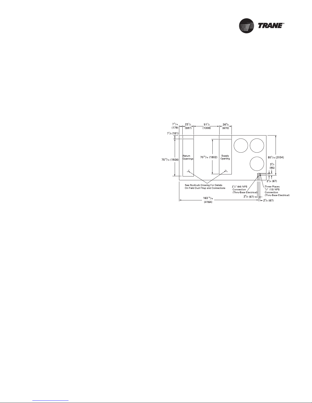
Roof Curb and Ductwork
The curbs for the 27.5 to 50 Ton commercial rooftop units
enclose the entire unit base area. They are referred to as
“full perimeter” type curbs.
Step-by-step instructions for the curb assembly and
installation with curb dimensions and curb configuration
for “A”, “B”, and “C” cabinets ship with each Trane
accessory roof curb kit. (See the latest edition of the curb
installation guide) Follow the instructions carefully to
assure proper fit when the unit is set into place.
The S/A and R/A ductwork adjoining the roof curb must be
fabricated and installed by the installing contractor before
the unit is set into place. Trane curbs include flanges
around the openings to accommodate duct attachment.
Ductwork installation recommendations are included in
the instruction booklet that ships with each Trane
accessory roof curb kit.
Note: For sound consideration, cut only the holes in the
roof deck for the supply and return duct
penetration. Do Not remove the roof decking from
the inside perimeter of the curb.
the unit into the ductwork. Refer to figures beginning on
page 13 for the S/A and R/A opening dimensions.
All outdoor ductwork between the unit and the structure
should be weather proofed after installation is completed.
If optional power exhaust is selected, an access door must
be field-installed on the horizontal return ductwork to
provide access to exhaust fan motors.
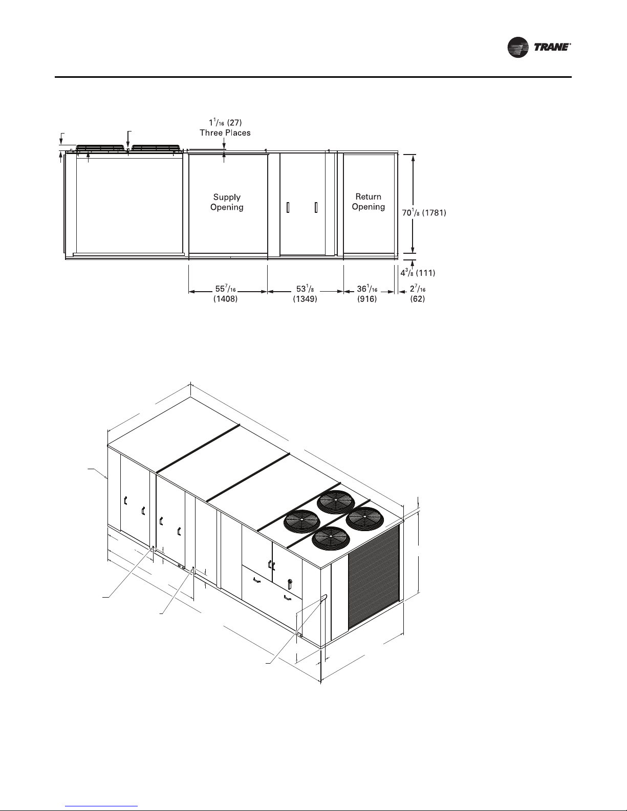
Figure 1. 60 Hz 27½-35, 50 Hz 23-29 Tons (TCD, TED,
YCD l ow heat)
If a Trane curb accessory kit is not used:
a. The ductwork can be attached directly to the S/A
and R/A openings. Be sure to use a flexible duct
connector at the unit.
b. For “built-up” curbs supplied by others, gaskets
must be installed around the curb perimeter flange,
Supply Air opening, and Return Air openings.
c. Insulation must be installed on the bottom of the
condenser section of the unit.
Horizontal Ductwork
When attaching the ductwork to a horizontal supply or
horizontal return unit, provide a water tight flexible
connector at the unit to prevent noise transmission from
RT-SVX34F-EN 13
Unit Dimensions and Weights
1 1/4
(32)
3 1/4
(81)
NOTES:
1. SEE DETAIL HOOD DRAWING FOR HORIZONTAL /
DOWNFLOW UNITS FOR ADDITIONAL DIMENSION
AND LOCATION.
179 3/4"
4565.65mm
42"
1066.8mm
83 13/16"
2128.8mm
90 1/16"
2287.5mm
180 5/16"
4579.9mm
90 3/8"
2295.5mm
5 3/8"
136.5mm
7 9/16"
192.1mm
3.25 [82.55mm] TO TOP OF FAN GRILLE
70 7/16"
1789.1mm
40 3/16"
1020.7mm
6 7/8"
174.6mm
1 1/4" [31.7mm]
FEMALE
PVC PIPE
3/4" [19.0mm] NPT
GAS INLET
SEE NOTE 2
CUSTOMER
CONNECTION POINT
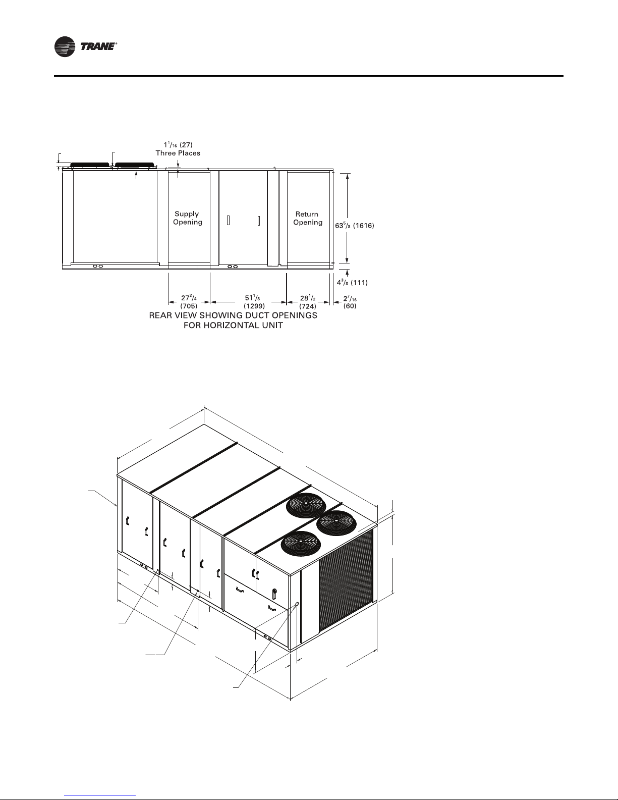
Figure 2. Rear view showing duct openings for horizontal supply and return, 60 Hz 27½-35, 50 Hz 23-29 Tons (TCH,
TEH, YCH low heat)
Notes:
• For combination of horizontal and downflow openings
• On horizontal units, the VFD is located between the
supply and return ductwork, which makes access
limited.
Figure 3. 60 Hz 27½-35, 50 Hz 23-29 Tons (TC, TE, YC low heat)
(digit 3 = F or R) see Figure 1, p. 13 for appropriate
downflow/upflow dimensions and Figure 2, p. 14 for
appropriate horizontal dimensions.
Note: Dimensions in ( ) are mm, 1”= 25.4 mm.
14 RT-SVX34F-EN
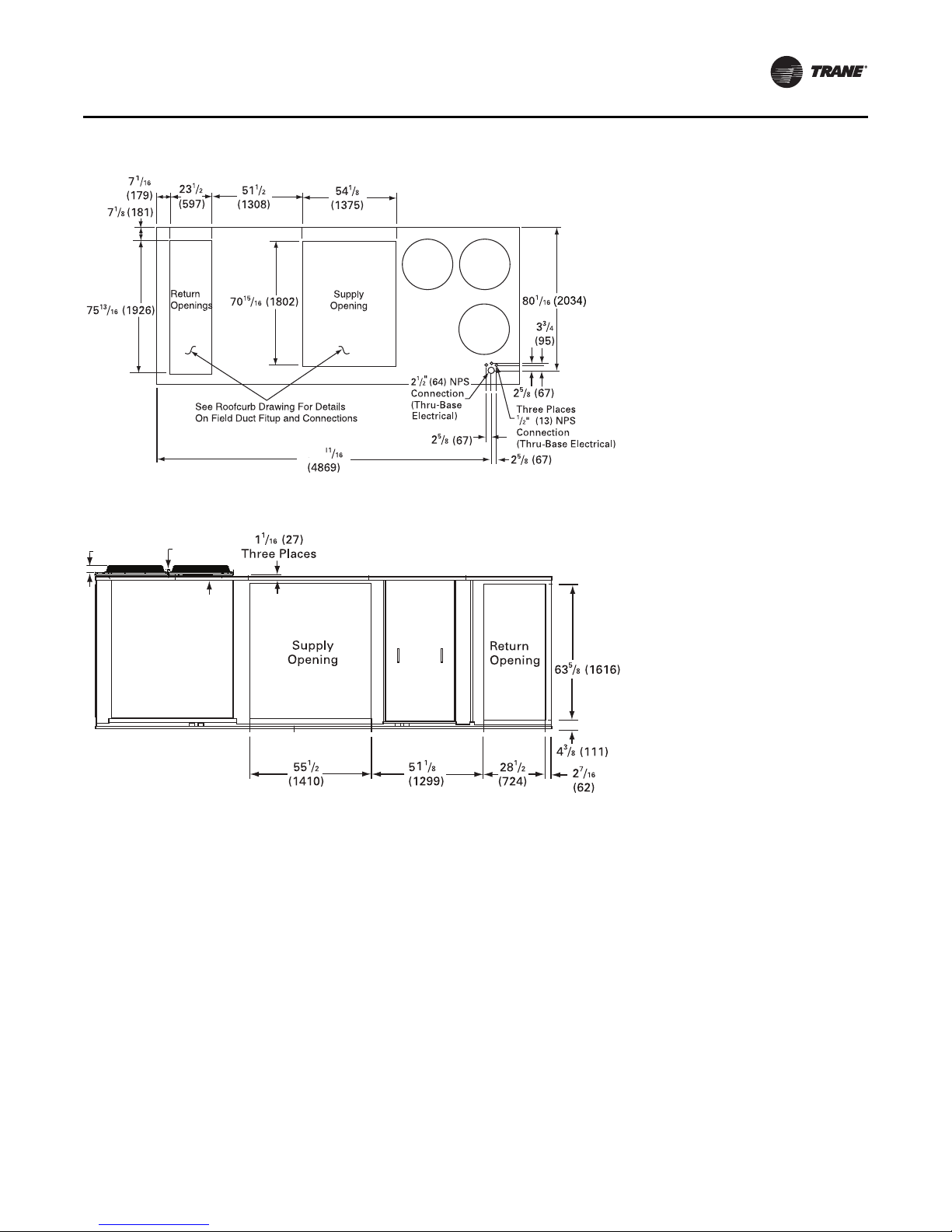
Figure 4. 60 Hz 27½-35, 50 Hz 23-29 Tons (YD high heat)
1 1/4
(32)
3 1/4
(81)
191
Figure 5. Duct openings, 60 Hz 27½-35, 50 Hz 23-29 Tons (YH high heat)
Unit Dimensions and Weights
Notes:
• On horizontal units, the VFD is located between the
supply and return ductwork, which makes access
limited.
• For combination of horizontal and downflow openings
(digit 3 = F or R) see Figure 4, p. 15 for appropriate
downflow/upflow dimensions and Figure 5, p. 15 for
appropriate horizontal dimensions.
RT-SVX34F-EN 15
Unit Dimensions and Weights
5270.5mm
207 1/2"
42"
5 3/8"
83 13/16"
2128.8mm
7 9/16"
208 1/16"
5284.7mm
90 5/8"
2301.8mm
90 1/16"
70 7/16"
40 3/16"
6 15/16"
PVC PIPE FEMALE
1" [25.4MM] NPT
GAS INLET
NOTES:
1. SEE ROOFCURB DRAWING FOR DETAILS
ON FIELD DUCT FITUP AND CONNECTIONS
2. SEE DETAIL HOOD DRAWING FOR HORIZONTAL /
DOWNFLOW UNITS FOR ADDITIONAL DIMENSION
AND LOCATION.
SEE NOTE 2
CUSTOMER
CONNECTION POINT
1066.8mm
2287.5mm
136.5m
192.1m
3.25 [82.55mm] TO
TOP OF FAN GRILLE
1789.1mm
1020.7mm
174.6mm
1 1/4" [31.7mm]
Figure 6. 60 Hz 27½-35, 50 Hz 23-29 Tons (YC high heat)
Note: Dimensions in ( ) are mm, 1”= 25.4 mm.
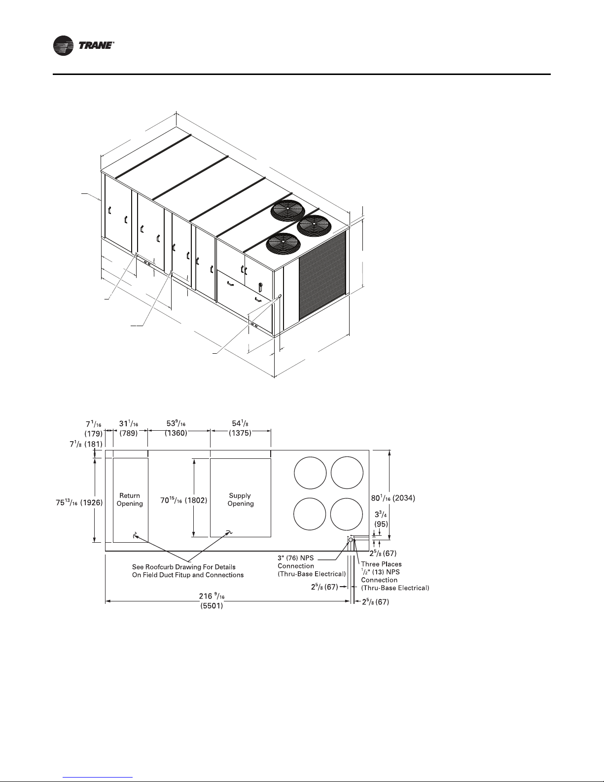
Figure 7. 60 Hz 40-50, 50 Hz 33-42 Tons (TD, TD, YD low and high heat)
16 RT-SVX34F-EN
Unit Dimensions and Weights
1 1/4
(32)
3 1/4
(81)
7 9/16"
232 3/8"
5902.3mm
232 3/4"
5911.8mm
90 5/8"
49 9/16"
1258.8mm
93 3/8"
2371.7mm
5 5/16"
90 1/16"
77"
1955.8mm
46 15/16"
1192.2mm
4 3/4"
120.6mm
NOTES:
1. SEE ROOFCURB DRAWING FOR DETAILS
ON FIELD DUCT FITUP AND CONNECTIONS
2. SEE DETAIL HOOD DRAWING FOR HORIZONTAL /
DOWNFLOW UNITS FOR ADDITIONAL DIMENSION
AND LOCATION.
SEE NOTE 2
CUSTOMER
CONNECTION POINT
2301.8mm
PVC PIPE FEMALE
1" [25.4MM] NPT
HIGH HEAT GAS INLET
2287.5mm
136.5m
192.1m
3.25 [82.55mm] TO
TOP OF FAN GRILLE
1 1/4" [31.7mm]
3/4" [19MM] NPT
LOW HEAT GAS INLET
Figure 8. Duct openings, 60 Hz 40-50, 50 Hz 33-42 Tons (TH, TH, YH low and high heat)
Notes:
• On horizontal units, the VFD is located between the
supply and return ductwork, which makes access
limited.
• For combination of horizontal and downflow openings
(digit 3 = F or R) see Figure 7, p. 16 for appropriate
downflow/upflow dimensions and Figure 8, p. 17 for
appropriate horizontal dimensions.
Figure 9. 60 Hz 40-50, 50 Hz 33-42 Tons (TC, TE, YC low and high heat)
Note: Dimensions in ( ) are mm, 1”= 25.4 mm.
RT-SVX34F-EN 17
Unit Dimensions and Weights
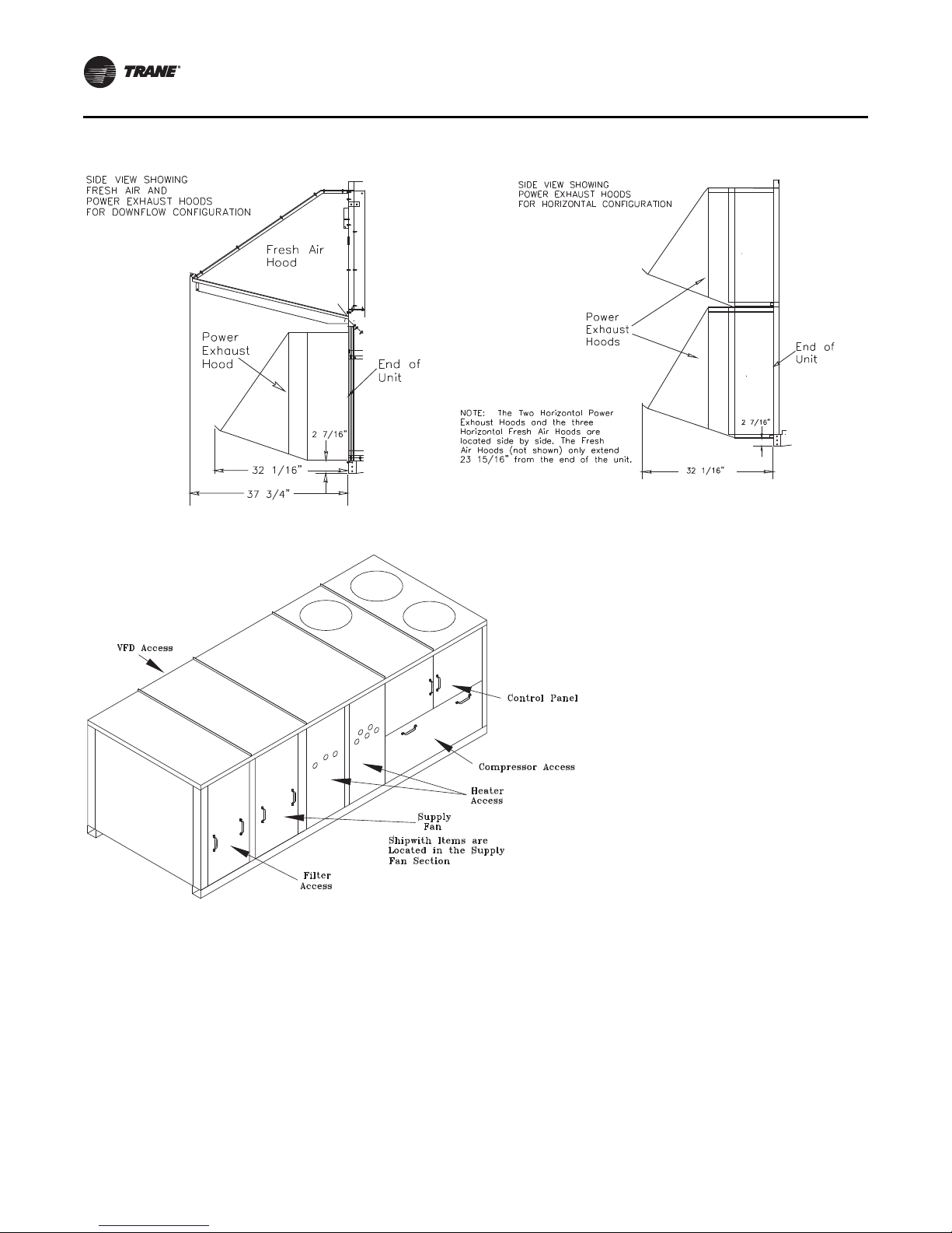
Figure 10. Fresh air and power exhaust dimensions for TC*, TE*, and YC* units
Figure 11. Location of “Ship With” items for TC*, TE*, and YC* units
18 RT-SVX34F-EN
Unit Dimensions and Weights
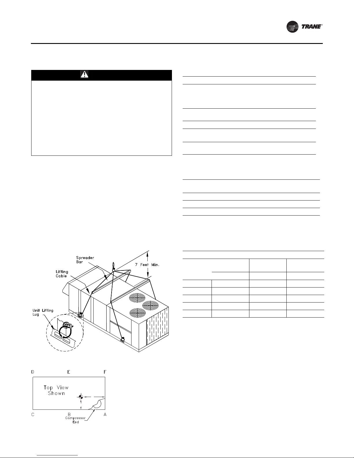
Unit Rigging and Placement
WARN ING
Heavy Objects!
Ensure that all the lifting equipment used is properly
rated for the weight of the unit being lifted. Each of the
cables (chains or slings), hooks, and shackles used to
lift the unit must be capable of supporting the entire
weight of the unit. Lifting cables (chains or slings) may
not be of the same length. Adjust as necessary for even
unit lift. Other lifting arrangements could cause
equipment or property damage. Failure to follow
instructions above or properly lift unit could result in
unit dropping and possibly crushing operator/
technician which could result in death or serious injury.
Use spreader bars as shown in the diagram. Refer to the
Installation manual or nameplate for unit weight. Refer to
the Installation instructions located inside the control
panel for further rigging information.
1. Verify that the roof curb has the proper gaskets
installed and is level and square to assure an adequate
curb-to-unit seal.
The units must be as level as possible in order to
assure proper condensate flow out of the unit. The
maximum side-to-side and end-to-end slope allowable
in any application is listed in Table 2, p. 19.
Table 1. Minimum operating clearances installation
(horizontal, downflow, and mixed airflow
configurations)
Recommended Clearances
Condenser
(a)
Coil
Single Unit
TC*, TE*, YC*
27.5 to 50 Tons
Multiple Unit
TC*, TE*, YC*
27.5 to 50 Tons
(a) Condenser coil is located at the end and side of the unit.
Economizer/
Exhaust End
6 Feet 8 Feet 4 Feet
Distance Between Units
Economizer/
Exhaust End End/Side
12 Feet 16 Feet 8 Feet
Orientation
End/Side
Service Side
Access
Service Side
Access
Table 2. Maximum slope
Cabinet
“A” (27.5 - 35 Ton Low Heat) 3 1/2 1 5/8
“B” (27.5 - 35 Ton High Heat) 4 1 5/8
“C” (All 40 and 50 Ton Units) 4 1/2 1 5/8
Note: Do not exceed these allowances. Correct the improper slope by
building up the curb base. The material used to raise the base must
be adequate to support both the curb and the unit weight.
End to End
(inches)
Side to Side
(inches)
Figure 12. Unit rigging
Figure 13. Center of gravity
Y
Z (see note 2)
X
Table 3. Center of gravity
Center-of-Gravity (inches)
YC Low Heat
Dimension
Unit Model
***330/275* 41 76 33 41 84 33 42 76 33
***360/305* 43 77 33 43 85 33 44 77 33
***420/350* 42 78 33 42 86 33 43 78 33
***480/400* 42 111 35 42 111 35 42 111 35
***600/500* 43 108 35 43 108 35 43 108 35
Note: Center-of-gravity dimensions are approximate, and are based on the
unit equipped with: standard efficiency coils, standard efficiency
motors, economizer, and throwaway filters.
Note: Z dimension is upward from the base of the unit.
Example:
Locating the center-of-gravity for a YC-360 MBH High Heat unit with 100%
exhaust.
X = 43 inches inward from the control panel side
Y = 85 inches inward from the compressor end
Z = 33 inches upward from the base
XY ZXY ZXY Z
YC High Heat
Dimension
TC/TE
Dimension
RT-SVX34F-EN 19
Unit Dimensions and Weights
DE F
TOP VIEW
OF UNIT
COMPRS
CBA
Table 4. Approximate units operating weights — lbs./
Unit
Model
**D330/275 3750 1701 4130 1873 3620 1642 3640 1651
**H330/275 3790 1719 4220 1914 3660 1660 3680 1669
**D360/305 3845 1744 4225 1916 3715 1685 3735 1694
**H360/305 3885 1762 4315 1957 3755 1703 3775 1712
**D420/350 3970 1801 4350 1973 3840 1742 3860 1751
**H420/350 4010 1819 4440 2014 3880 1760 3900 1769
**D480/400 4764 2161 4884 2215 4539 2059 4564 2070
**H480/400 4859 2204 4984 2261 4599 2091 4634 2102
**D600/500 5174 2347 5294 2401 4949 2245 4974 2256
**D600/500 5269 2390 5394 2447 5019 2277 5044 2288
Notes:
1. Basic unit weight includes minimum horsepower supply fan
motor.
1
kg
Basic Unit Weights
1
YC
Low HeatYCHigh Heat TC TE
Table 5. Point loading average weight
1,2
— lbs./kg
Model A B C D E F
**D330/275 846 384 688 313 743 337 745 338 604 275 503 228
**H330/275 867 393 707 321 767 348 753 342 613 279 513 233
**D360/305 836 379 680 309 779 353 741 336 621 285 568 258
**H360/305 897 407 696 316 766 348 729 330 590 268 636 288
**D420/350 892 405 692 314 779 353 765 347 633 288 590 268
**H420/350 867 393 869 395 690 313 758 344 601 273 654 297
**D480/400 820 372 856 388 937 425 742 336 762 346 769 349
**H480/400 841 381 876 397 957 434 754 342 775 352 782 355
**D600/500 894 406 955 428 970 440 756 343 862 391 866 393
**H600/500 915 415 966 438 990 449 768 348 875 397 879 399
Notes:
1. Point Loading is identified with corner A being the corner with the
compressors. As you move clockwise around the unit as viewed
from the top, mid-point B, corner C, corner D, mid-point E and
corner F.
2. Point load calculations provided are based on the unit weight for YC
high heat gas models.
Table 6. Approximate operating weights1— optional components — lbs./kg
Unit
Model
**D330/275 110/50 165/74 50/23 260/117 85/39 115/52 18/8 6/3 30/14 85/38 310/141 330/150
**H330/300 145/65 200/90 50/23 285/128 85/39 115/52 18/8 6/3 30/14 85/38 310/141 330/150
**D360/305 110/50 165/74 50/23 260/117 85/39 115/52 18/8 6/3 30/14 85/38 310/141 330/150
**H330/305 145/65 200/90 50/23 285/128 85/39 115/52 18/8 6/3 30/14 85/38 310/141 330/150
**D420/350 110/50 165/74 50/23 260/117 85/39 115/52 18/8 6/3 30/14 85/38 310/141 330/150
**H420/350 145/65 200/90 50/23 285/128 85/39 115/52 18/8 6/3 30/14 85/38 310/141 330/150
**D480/400 110/50 165/74 50/23 290/131 115/52 150/68 18/8 6/3 30/14 85/38 365/169 365/169
**H480/400 145/65 200/90 50/23 300/135 115/52 150/68 18/8 6/3 30/14 85/38 365/169 365/169
**D600/500 110/50 165/74 50/23 290/131 115/52 150/68 18/8 6/3 30/14 85/38 365/169 365/169
**H600/500 145/65 200/90 50/23 300/135 115/52 150/68 18/8 6/3 30/14 85/38 365/169 365/169
Note:
1. Basic unit weight includes minimum horsepower supply fan motor.
Baro.
Relief
Power
Exhaust
0-25%
Man
Damper Econ.
20 RT-SVX34F-EN
Var. Freq.
Drives (VFD’s)
Bypass Lo Hi
Valves
Serv
Through-
the
base
Elec.
Non-
Fused
Discon.
Switch
Factory.
GFI with
Discon.
Switch
Roof CurbW/O With
Installation General Requirements
Condensate Drain Connection
Each commercial rooftop unit is equipped with one (1) 11/4 inch Female PVC condensate drain connection.
Refer to Figure 11, p. 18 for the location of the connector.
A condensate trap must be installed due to the drain
connection being on the “negative pressure” side of the
fan. Install a P-Trap at the unit using the guidelines in
Figure 14, p. 21.
Pitch the drain line at least 1/2 inch for every 10 feet of
horizontal run to assure proper condensate flow.
Ensure that all condensate drain line installations comply
with applicable building and waste disposal codes.
Figure 14. Condensate trap installation
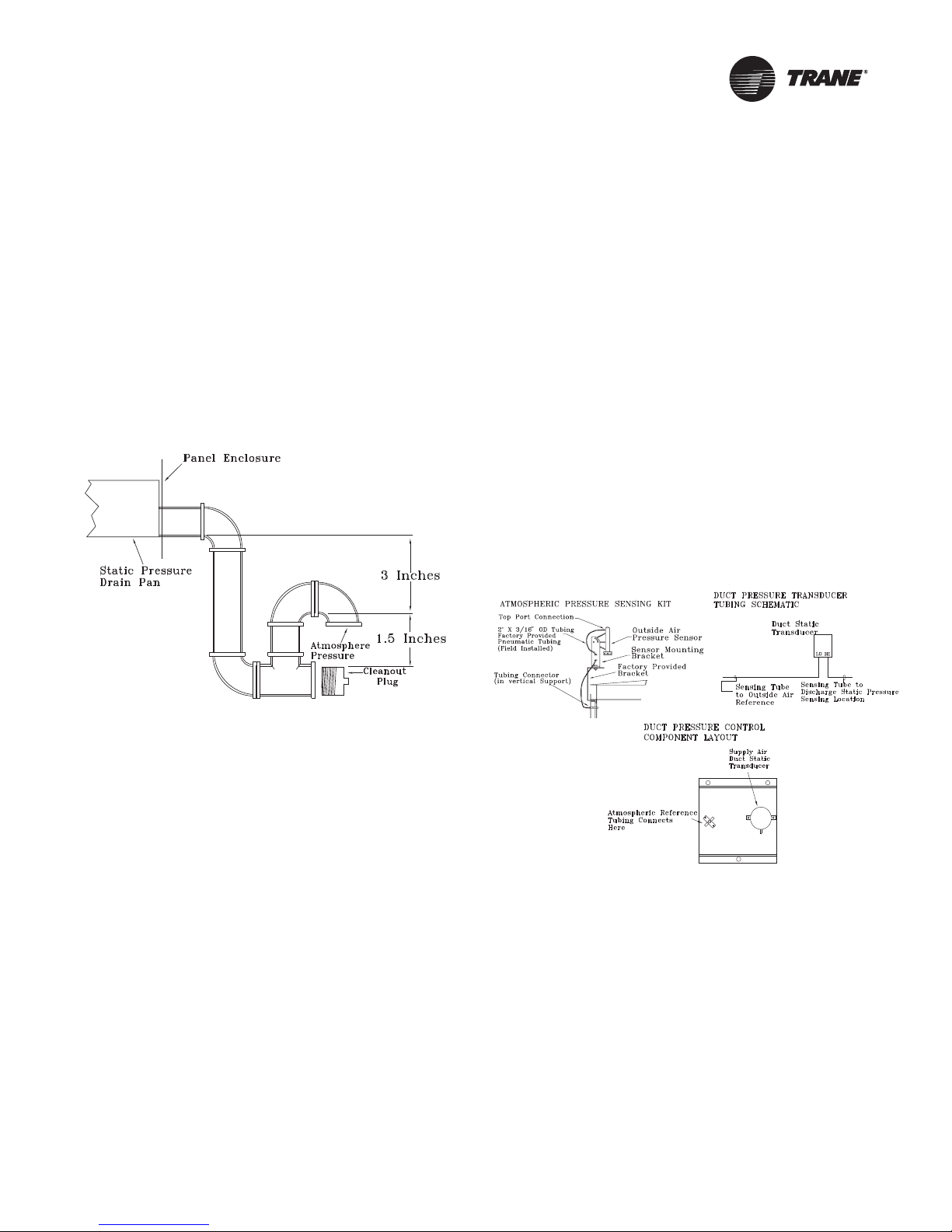
4. Remove the dust cap from the tubing connector
located below the sensor in the vertical support.
5. Attach one end of the 50' x 3/16” O.D. factory provided
pneumatic tubing to the sensor's top port, and the
other end of the tubing to the connector in the vertical
support. Discard any excess tubing.
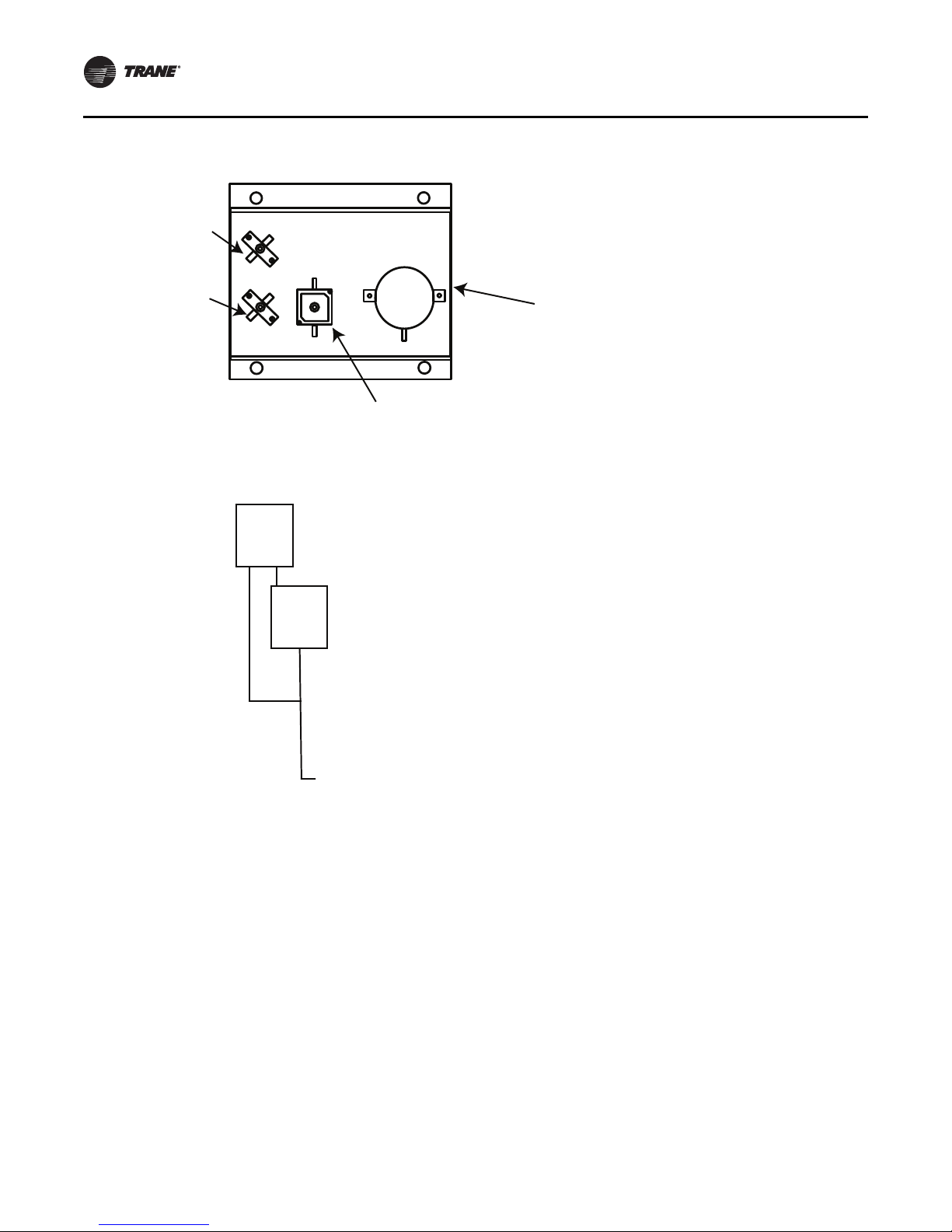
Units with Statitrac™
1. Open the filter access door, and locate the Statitrac
Transducer Assembly illustrated in Figure 16, p. 22.
There are two tube connectors mounted on the left of
the solenoid and transducers. Connect one end of the
field provided 1/4” (length 50-100 ft.) or 3/8” (length
greater than 100 ft.) O.D. pneumatic tubing for the
space pressurization control to the fitting indicated in
the illustration.
2. Route the opposite end of the tubing to a suitable
location inside the building. This location should be
the largest open area that will not be affected by
sudden static pressure changes.
Figure 15. Pressure tubing
O/A Sensor & Tubing Installation
An Outside Air Pressure Sensor is shipped with all units
designed to operate on traditional variable air volume
applications (non-SZ VAV) and units with Statitrac™.
A duct pressure transducer and the outside air sensor is
used to control the discharge duct static pressure to within
a customer-specified controlband. Refer to the illustration
in Figure 15, p. 21 and the following steps to install the
sensor and the pneumatic tubing.
1. Remove the O/A pressure sensor kit located inside the
fan section. The kit contains the following items;
• an O/A static pressure sensor
• a sensor mounting bracket
• 50’ of 3/16” O.D. pneumatic tubing
• mounting hardware
2. Using two #10-32 x 1-3/4” screws provided, install the
sensor's mounting bracket to the factory provided
bracket (near the fan section).
3. Using the #10-32 x 1/2” screws provided, install the O/
A static pressure sensor vertically to the sensor
bracket.
RT-SVX34F-EN 21
Installation General Requirements
Static Reference
Tubing Connects
Here (O/A Sensor)
Space Pressure
Sensing Tube
Connects Here
Space Pressure
Calibration
Solenoid
Space Pressure
Transducer
LO
HI
CNO
NC
Sensing Tube
to Outside Air
Reference
Space Pressure
Transducer
Sensing Tube
to Space
Pressure
Figure 16. Statitrac transducer assembly
22 RT-SVX34F-EN
Installation Electrical
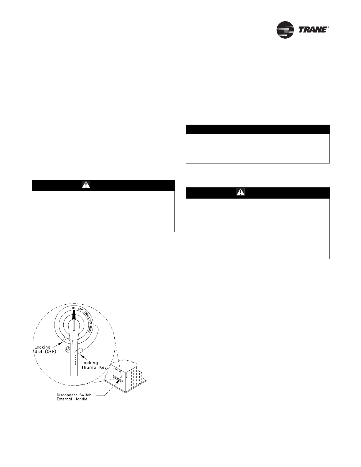
Disconnect Switch External
Handle (Factory Mounted Option)
Units ordered with the factory mounted disconnect switch
come equipped with an externally mounted handle. This
allows the operator to disconnect power from the unit
without having to open the control panel door. The handle
location and its three positions are shown below;
ON - Indicates that the disconnect switch is closed,
allowing the main power supply to be applied at the unit.
OFF - Indicates that the disconnect switch is open,
interrupting the main power supply at the unit.
OPEN COVER/RESET - Turning the handle to this position
releases the handle from the disconnect switch, allowing
the control panel door to be opened.
WARNI NG
Hazardous Voltage!
Disconnect all electric power, including remote
disconnects before servicing. Follow proper lockout/
tagout procedures to ensure the power can not be
inadvertently energized. Failure to disconnect power
before servicing could result in death or serious injury.
Once the door has been opened, it can be closed with the
handle in any one of the three positions outlined above,
provided it matches the disconnect switch position. The
handle can be locked in the “OFF” position. While holding
the handle in the “OFF” position, push the spring loaded
thumb key, attached to the handle, into the base slot. Place
the lock shackle between the handle and the thumb key.
This will prevent it from springing out of position.
Figure 17. Disconnect switch
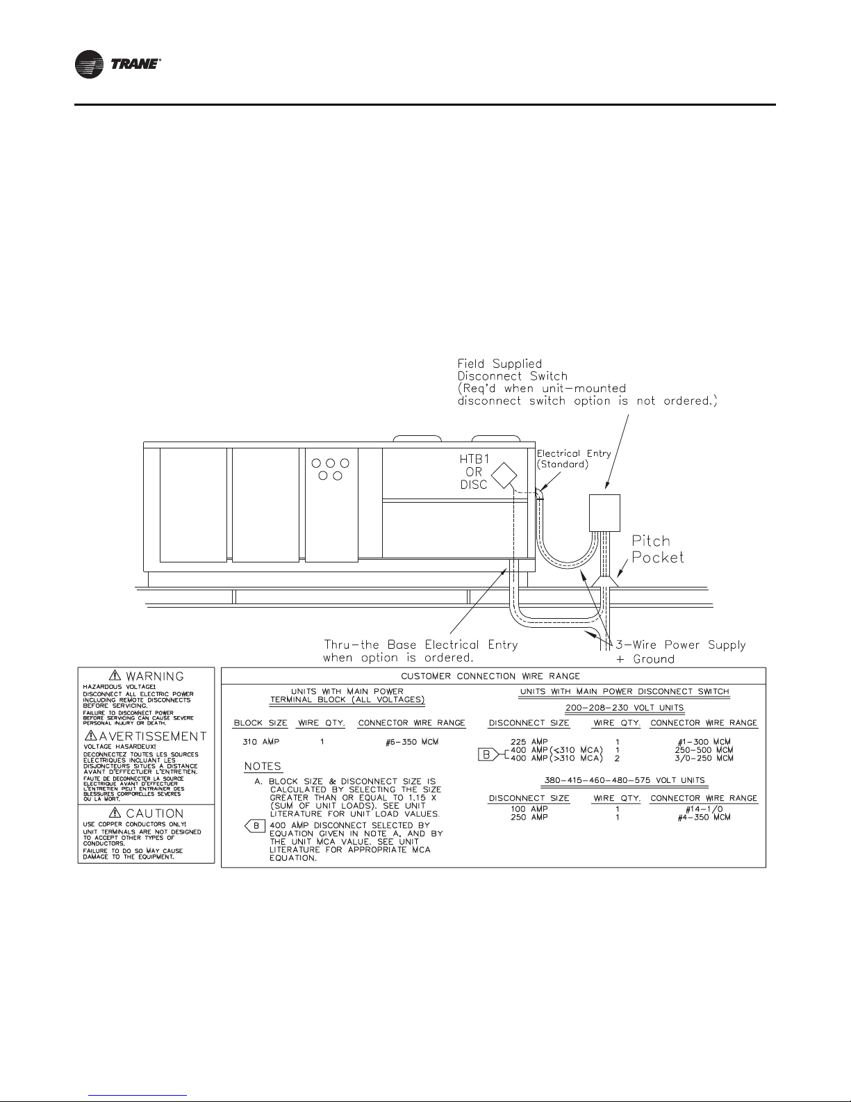
An overall layout of the field required power wiring is
illustrated in Figure 18, p. 24. To insure that the unit supply
power wiring is properly sized and installed, follow the
guidelines outlined below.
Note: All field installed wiring must conform to NEC
guidelines as well as State and Local codes.
Verify that the power supply available is compatible with
the unit's name plate ratings for all components. The
available power supply must be within 10% of the rated
voltage stamped on the nameplate. Use only copper
conductors to connect the 3-phase power supply to the
unit.
NOTICE:
Use Copper Conductors Only!
Unit terminals are not designed to accept other types of
conductors. Failure to use copper conductors could
result in equipment damage.
Main Power Wiring
WARNI NG
Proper Field Wiring and Grounding
Required!
All field wiring MUST be performed by qualified
personnel. Improperly installed and grounded field
wiring poses FIRE and ELECTROCUTION hazards. To
avoid these hazards, you MUST follow requirements for
field wiring installation and grounding as described in
NEC and your local/state electrical codes. Failure to
follow code could result in death or serious injury.
1. Table 7, p. 25 and Ta b le 10 , p . 2 6 list the electrical
service sizing data. The electrical service must be
protected from over current and short circuit
conditions in accordance with NEC requirements.
Protection devices must be sized according to the
electrical data on the nameplate. Refer to “Electrical
Wire Sizing and Protection Device Equations” on
page 27 for determining:
a. The appropriate electrical service wire size based
on “Minimum Circuit Ampacity” (MCA),
b. The “Maximum Over current Protection” (MOP)
device.
c. The “Recommended Dual Element fuse size” (RDE).
2. If the unit is not equipped with an optional factory
installed Nonfused disconnect switch, a field supplied
disconnect switch must be installed at or near the unit
in accordance with the National Electrical Code (NEC
latest edition). Refer to DSS calculations
Wire Sizing and Protection Device Equations” on
page 27 for determining correct size.
Location for the electrical service entrance is shown in
the unit dimensional drawings beginning with
Figure 1, p. 13. Complete the unit's power wiring
connections onto either the main terminal block HTB1,
“Electrical
RT-SVX34F-EN 23
Installation Electrical
or the factory mounted nonfused disconnect switch
inside the unit control panel.
Note: When the factory installed through-the-base
option is not used, the installing contractor is
required to seal any holes made in the base of the
unit to prevent water from leaking into the building.
3. Provide proper grounding for the unit in accordance
with local and national codes.
Figure 18. Typical field power wiring
Through-the-Base Electrical (Optional
Accessory)
Liquid-tight conduit couplings are secured to the base of
the unit for both power and control wiring. Liquid-tight
conduit must be field installed between the couplings and
the unit control box to prevent water leaks into the
building.
Note: If the unit is set on the roof curb and temporary
auxiliary heat is provided in the building, it is
recommended that the electrical and control wiring
conduit opening in the control box be temporarily
sealed to provide a vapor barrier.
24 RT-SVX34F-EN
Installation Electrical
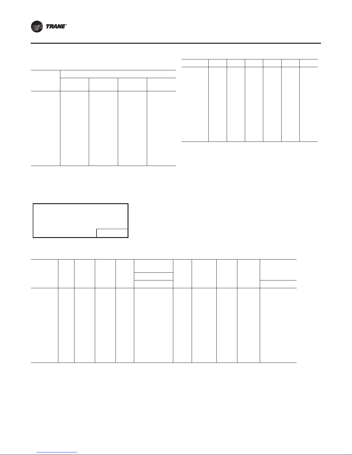
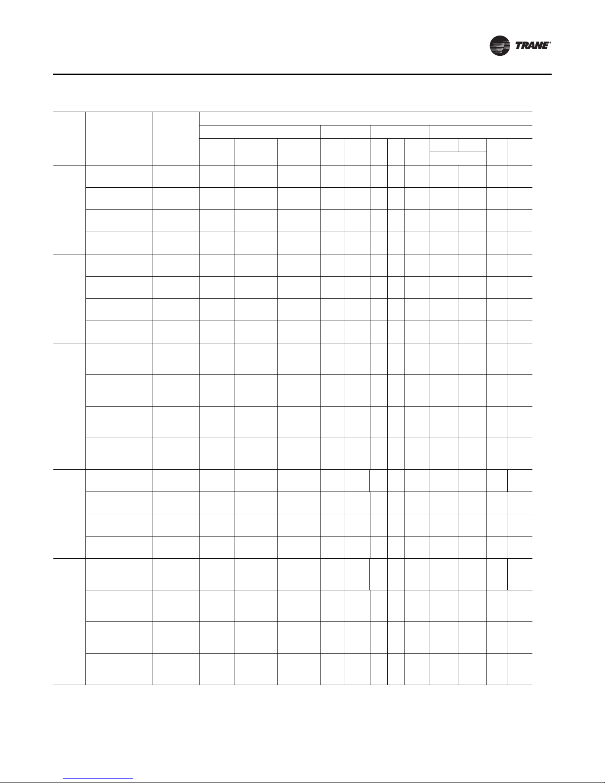
Table 7. 27½-50 ton electrical service sizing data—60Hz
1
Fan Motors
Model
TC/TE/
YC*330
TC/TE/
YC*360
TC/TE/
YC*420
TC/TE/
YC*480
TC/TE/
YC*600
Notes:
1. All customer wiring and devices must be installed in accordance with local and national electrical codes.
2. 100% Power Exhaust is with or without Statitrac™.
Characteristics
208/60/3 187-229
230/60/3 207-253
460/60/3 414-506
575/60/3 517-633
208/60/3 187-229 2/13 50.5 315/315
230/60/3 207-253 2/13 50.5 315/315
460/60/3 414-506 2/13 23.0 158/158
575/60/3 517-633 2/13 19.0 136/136
208/60/3 187-229
230/60/3 207-253
460/60/3 414-506
575/60/3 517-633
208/60/3 187-229
230/60/3 207-253
460/60/3 414-506
575/60/3 517-633
208/60/3 187-229
230/60/3 207-253
460/60/3 414-506
575/60/3 517-633
Electrical
Voltage
Range
No/Ton RLA (Ea.) LRA (Ea.) HP FLA No HP
1/12,1/
1/12,1/
1/12,1/
1/12,1/
1/13,1/
1/13,1/
1/13,1/
1/13,1/
1/13,1/
1/13,1/
1/13,1/
1/13,1/
2/13,1/
2/13,1/
2/13,1/
2/13,1/
Allowable
Compressor Supply Condenser Exhaust
7.5
44.0/50.5 304/315
13
44.0/50.5 304/315
13
21.0/23.0 147/158
13
17.5/19.0 122/136
13
50.5/56.0 315/351
15
50.5/56.0 315/351
15
15
23.0/27.5 158/197
15
19.0/23.0 136/146
50.5/83.9 315/485
20
50.5/83.9 315/485
20
23.0/34.0 158/215
20
19.0/27.3 136/175
20
50.5/56.0 315/351
15
50.5/56.0 315/351
15
23.0/27.5 158/197
15
19.0/23.0 136/146
15
10.0
7.5
10.0
7.5
10.0
7.5
10.0
7.5
10.0
7.5
10.0
7.5
10.0
7.5
10.0
7.5
10.0
15.0
7.5
10.0
15.0
7.5
10.0
15.0
7.5
10.0
15.0
10.0
15.0
10.0
15.0
10.0
15.0
10.0
15.0
10.0
15.0
20.0
10.0
15.0
20.0
10.0
15.0
20.0
10.0
15.0
20.0
22.2
3 1.1 7.0 1 2 1.0 4.1
29.5
18.8
3 1.1 7.0 1 2 1.0 4.1
25.2
9.4
3 1.1 3.5 1 2 1.0 1.8
12.6
7.8
3 1.1 2.8 1 2 1.0 1.4
10.1
22.2
3 1.1 7.0 1 2 1.0 4.1
29.5
18.8
3 1.1 7.0 1 2 1.0 4.1
25.2
9.4
3 1.1 3.5 1 2 1.0 1.8
12.6
7.8
3 1.1 2.8 1 2 1.0 1.4
10.1
22.2
29.5
3 1.1 7.0 1 2 1.0 4.1
40.7
18.8
25.2
3 1.1 7.0 1 2 1.0 4.1
35.4
9.4
12.6
3 1.1 3.5 1 2 1.0 1.8
17.7
7.8
10.1
3 1.1 2.8 1 2 1.0 1.4
15.1
29.5
4 1.1 7.0 1 2 1.5 5.4
40.7
25.2
4 1.1 7.0 1 2 1.5 5.4
35.4
12.6
4 1.1 3.5 1 2 1.5 2.7
17.7
10.1
4 1.1 2.8 1 2 1.5 2.2
15.1
29.5
40.7
4 1.1 7.0 1 2 1.5 5.4
56.1
25.2
35.4
4 1.1 7.0 1 2 1.5 5.4
49.4
12.6
17.7
4 1.1 3.5 1 2 1.5 2.7
24.7
10.1
15.1
4 1.1 2.8 1 2 1.5 2.2
19.6
FLA
(Ea.)
50% 100%
HP
FLA
(Ea.)No.
RT-SVX34F-EN 25
Installation Electrical
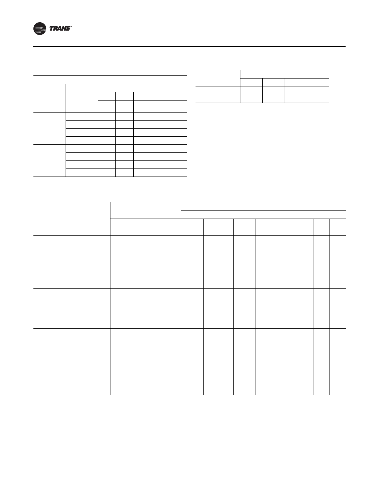
Table 8. Electrical service sizing data — electric heat
module (electric heat only) — 60 Hz
Models: TE(D,H,F,R) 330—600 Electric Heat FLA
KW Heater
Nominal
Unit Size
(Tons)
27½-35
40- 50
Note: All FLA in this table are based on heater operating at 208, 240, 480,
and 600 volts.
Nominal
36 54 72 90 108
Unit
Voltage
208 74.9 112.4 — — —
230 86.6 129.9 — — —
460 43.3 65.0 86.6 108.3 —
575 — 52.0 69.3 86.6 —
208 — 112.4 — — —
230 — 129.9 — — —
460 — 65.0 86.6 108.3 129.9
575 — 52.0 69.3 86.6 103.9
FLA FLA FLA FLA FLA
Table 9. Electrical service sizing data — crankcase
heaters (heating mode only) — 60Hz
Nominal
Unit Size (Tons)
27½ - 35 1111
40, 50 2211
FLA Add Unit Voltage
200 230 460 575
Table 10. Electrical service sizing data — 50Hz
Fan Motors
Compressor
Model
TC/TE/YC*275 380-415/50/3 1/10, 1/11 21.0/23.0 147/ 158 7.5 (5.6)
TC/TE/YC*305 380-415/50/3 2/11 23.0 158 7.5 (5.6)
TC/TE/YC*350 380-415/50/3 1/11, 1/12 23.0/27.5 158/ 197 7.5 (5.6)
TC/TE/YC*400 380-415/50/3 1/11, 1/17 23.0/34.0 158/ 215 10 (6.8)
TC/TE/YC*500 380-415/50/3 2/11, 1/12 23.0/27.5 158/ 197 10 (6.8)
Notes:
1. All condenser fan motors are single phase.
2. All customer wiring and devices must be installed in accordance with local and national electrical codes.
3. Allowable voltage range for the 380V unit is 342-418V, allowable voltage range for the 415V unit is 373-456.
4. 100% Power Exhaust is with or without Statitrac.
Characteristics
No/Ton
Electrical
RLA
(Ea.)
LRA
(Ea.) HP(kW) FLA No. HP(kW)
Supply Condenser
10 (6.8)
10 (6.8)
10 (6.8)
15 (10.5)
15 (10.5)
15 (10.5)
20 (12.8)
13.6/
16.0/
13.6/
16.0/
13.6/
16.0/
24.0/
16.0/
24.0/
16.0/
24.0/
29.0/
3 .75 (.56) 4.4 1 2
14.1
15.5
3
14.1
15.5
3
14.1
15.5
26.0
4
15.5
26.0
4
15.5
26.0
28.0
0.75
(0.56)
0.75
(0.56)
0.75
(0.56)
0.75
(0.56)
1
50% 100%
FLA
(Ea.)
4.4 1 2
4.4 1 2
4.4 1 2
4.4 1 2
Exhaust
4
(kW)
(0.56)
(0.56)
(0.56)
(0.75)
(0.75)
HP
0.75
0.75
0.75
1.0
1.0
FLA
(Ea.)No.
1.7
1.7
1.7
2.5
2.5
26 RT-SVX34F-EN
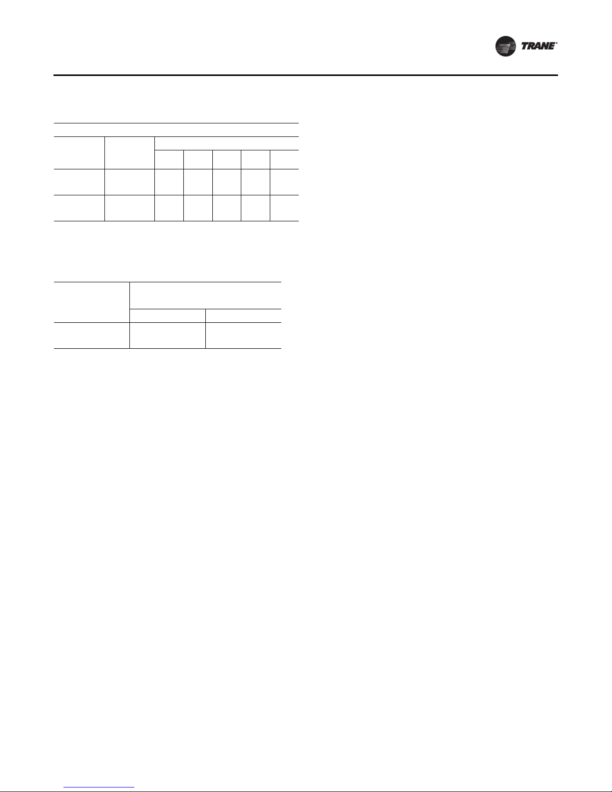
Table 11. Electrical service sizing data – electric heat
module (electric heat units only)—50Hz
Models: TE(D,H,F,R) 275 through 500 Electric Heat FLA
Nominal
Unit Size
(Tons)
23-29
33, 42
Note: All FLA in this table are based on heater operating at 380 or 415 volts
as shown above.
Nominal
Unit
Voltage
380 34.5 51.1 68.9 85.5 –
415 37.6 55.6 – – –
380 – 51.1 68.9 85.5 103.4
415 – 55.6 75.1 93.2 112.7
KW Heater (380/415V)
23/27 34/40 45/54 56/67 68/81
Table 12. Electrical service sizing data — crankcase
heaters (heating mode only) — 50Hz
FLA Add
Nominal Unit Size
(Tons)
23 - 29 1 1
33 - 42 1 1
Unit Voltage
380 415
Electrical Wire Sizing and
Protection Device Equations
To correctly size the main power wiring based on MCA
(Minimum Circuit Ampacity), use the appropriate
equation listed below. Read the definitions that follow and
then use Calculation #1 for determining MCA (Minimum
Circuit Ampacity), MOP (Maximum Over current
Protection), and RDE (Recommended Dual Element fuse
size) for TC (Cooling Only) units and YC (Cooling with Gas
Heat) units. Use Calculation #2 for TE (Cooling with Electric
Heat) units.
Load Definitions:
• LOAD 1 = CURRENT OF THE LARGEST MOTOR
(Compressor or Fan Motor)
• LOAD 2 = SUM OF THE CURRENTS OF ALL
REMAINING MOTORS
• LOAD 3 = FLA (Full Load Amps) OF THE ELECTRIC
HEATER
• LOAD 4 = ANY OTHER LOAD RATED AT 1 AMP OR
MORE
• CRANKCASE HEATERS FOR HEATING MODE ONLY:
• 208/230 VOLT
– 27.5 - 35 Ton Units, Add 1 Amp
– 40 - 50 Ton Units, Add 2 Amps
• 460/575 VOLT
– 27.5 - 35 Tons Units, Add 1 Amp
– 40 - 50 Ton Units, Add 1 Amp
Installation Electrical
Calculation #1 - TC*, YC*-27.5 to 50 Ton Units
MCA = (1.25 x Load 1) + Load 2 + Load 4
MOP = (2.25 x Load 1) + Load 2 + Load 4 (See Note 1)
RDE = (1.5 x Load 1) + Load 2 + Load 4 (See Note 2)
Calculation # 2 - TE*-27.5 to 50 Ton Units
A. Single Source Power (all voltages)
To calculate the correct MCA (Minimum Circuit Ampacity),
MOP (Maximum Over current Protection), and RDE
(Recommended Dual Element fuse size), two (2) sets of
calculations must be performed;
1. Calculate the MCA, MOP and/or RDE values using the
above equation as if the unit is operating in the cooling
mode.
2. Calculate the MCA, MOP and/or RDE values as if the
unit is operating in the heating mode, as follows:
Note: When determining loads, the compressors and
condenser fan motors do not operate during the
heating cycle.
Units with less than 50 KW Heaters
MCA = 1.25 x (Load 1 + Load 2 + Load 4) + (1.25 x Load 3)
Units with 50 KW or Larger Heaters
MCA = 1.25 x (Load 1 + Load 2 + Load 4) + Load 3
The MCA value stamped on the nameplate is the largest of
the two calculated values.
MOP = (2.25 x Load 1) + Load 2 + Load 3 + Load 4 (See Note
1)
The MOP value stamped on the nameplate is the largest of
the two calculated values.
RDE = (1.5 x Load 1) + Load 2 + Load 3 + Load 4 (See Note 2)
Note: Select an over current protection device equal to
the MOP value. If the calculated MOP value does
not equal a standard size protection device listed in
NEC 240-6, select the next lower over current
protection device. If the calculated MOP value is
less than the MCA value, select the lowest over
current protection device which is equal to or larger
than the MCA, providing the selected over current
device does not exceed 800 amps.
Note: Select a Dual Element Fuse equal to the RDE value.
If the calculated RDE value does not equal a
standard dual element fuse size listed in NEC 2406, select the next higher fuse size. If the calculated
RDE value is greater than the MOP value, select a
Dual Element fuse equal to the calculated MOP
(Maximum Over current Protection) value
RT-SVX34F-EN 27

Installation Electrical
Disconnect Switch Sizing (DSS)
Calculation A. - YC*, TC*, and TE* Units:
DSS = 1.15 X (LOAD1 + LOAD2 + LOAD4)
For TE* units, use calculations A and B.
Calculation B. - TE* Units:
DSS = 1.15 X (LOAD3 + Supply Fan FLA + Exhaust
Fan FLA).
Use the larger value of calculations A or B to size the
electrical disconnect switch.
Low Voltage Wiring
An overall layout of the various control options available
for a Constant Volume application is illustrated in
Figure 19, p. 30 and Figure 20, p. 31 illustrates the various
control options for a Variable Air Volume application. The
required number of conductors for each control device are
listed in the illustration.
A typical field connection diagram for the sensors and
other options are shown in the following section “Remote
Panels and Sensors”. These diagrams are representative of
standard applications and are provided for general
reference only. Always refer to the wiring diagram that
shipped with the unit for specific electrical schematic and
connection information.
Note: All field wiring must conform to NEC guidelines as
well as state and local codes.
Control Power Transformer
WARN ING
Hazardous Voltage!
Disconnect all electric power, including remote
disconnects before servicing. Follow proper lockout/
tagout procedures to ensure the power can not be
inadvertently energized. Failure to disconnect power
before servicing could result in death or serious injury.
The 24 volt control power transformers are equipped with
internal circuit breakers. They are to be used only with the
accessories called out in this manual. If a circuit breaker
trips, be sure to turn off all power to the unit before
attempting to reset it.
On units equipped with the VFD option, an additional
control power transformer is used. The secondary is
protected with fuses. Should the fuse blow, be sure to turn
off all power to the unit before attempting to replace it.
Field Installed AC Control Wiring
WARNI NG
Proper Field Wiring and Grounding
Required!
All field wiring MUST be performed by qualified
personnel. Improperly installed and grounded field
wiring poses FIRE and ELECTROCUTION hazards. To
avoid these hazards, you MUST follow requirements for
field wiring installation and grounding as described in
NEC and your local/state electrical codes. Failure to
follow code could result in death or serious injury.
NOTICE:
Use Copper Conductors Only!
Unit terminals are not designed to accept other types of
conductors. Failure to use copper conductors could
result in equipment damage.
Before installing any connecting wiring, refer to Tab l e 13 ,
p. 28 for conductor sizing guidelines and;
• Use copper conductors unless otherwise specified.
• Ensure that the AC control voltage wiring between
the controls and the unit's termination point does
not exceed three (3) ohms/conductor for the length
of the run.
Note: Resistance in excess of 3 ohms per conductor may
cause component failure due to insufficient AC
voltage supply.
• Refer to dimensional information beginning with
Figure 1, p. 13 for the electrical access locations
provided on the unit.
• Do not run the AC low voltage wiring in the same
conduit with the high voltage power supply wiring.
Be sure to check all loads and conductors for grounds,
shorts, and miswiring. After correcting any discrepancies,
reset the circuit breakers by pressing the black button
located on the left side of the transformer.
Table 13. AC conductors
Distance from unit to control Recommended wire size
000-460 feet 18 gauge
461-732 feet 16 gauge
733-1000 feet 14 gauge
28 RT-SVX34F-EN
Installation Electrical
Field Installed DC Control Wiring
WARN ING
Proper Field Wiring and Grounding
Required!
All field wiring MUST be performed by qualified
personnel. Improperly installed and grounded field
wiring poses FIRE and ELECTROCUTION hazards. To
avoid these hazards, you MUST follow requirements for
field wiring installation and grounding as described in
NEC and your local/state electrical codes. Failure to
follow code could result in death or serious injury.
NOTICE:
Use Copper Conductors Only!
Unit terminals are not designed to accept other types
of conductors. Failure to use copper conductors could
result in equipment damage.
Before installing the connecting wiring between the
components utilizing a DC analog output/input signal and
the unit, refer to Table 14, p. 29 for conductor sizing
guidelines and;
• Use standard copper conductor thermostat wire
unless otherwise specified.
• Ensure that the wiring between the controls and the
unit's termination point does not exceed two and a
half (2-1/2) ohms/conductor for the length of the
run.
Note: Resistance in excess of 21/2 ohms per conductor
can cause deviations in the accuracy of the
controls.
• Refer to dimensional drawings beginning with
Figure 1, p. 13 for the electrical access locations
provided on the unit.
• Do not run the electrical wires transporting DC
signals in or around conduit housing high voltage
wires.
• Must not pass between buildings.
Table 14. DC conductors
Distance from unit to control Recommended wire size
000-150 feet 22 gauge
151-240 feet 20 gauge
241-385 feet 18 gauge
386-610 feet 16 gauge
611-970 feet 14 gauge
Units equipped with the Trane Communication Interface
(TCI) option, which utilizes a serial communication link;
• Must be 18 AWG shielded twisted pair cable Belden
8760 or equivalent).
• Must not exceed 5,000 feet maximum for each link.
RT-SVX34F-EN 29
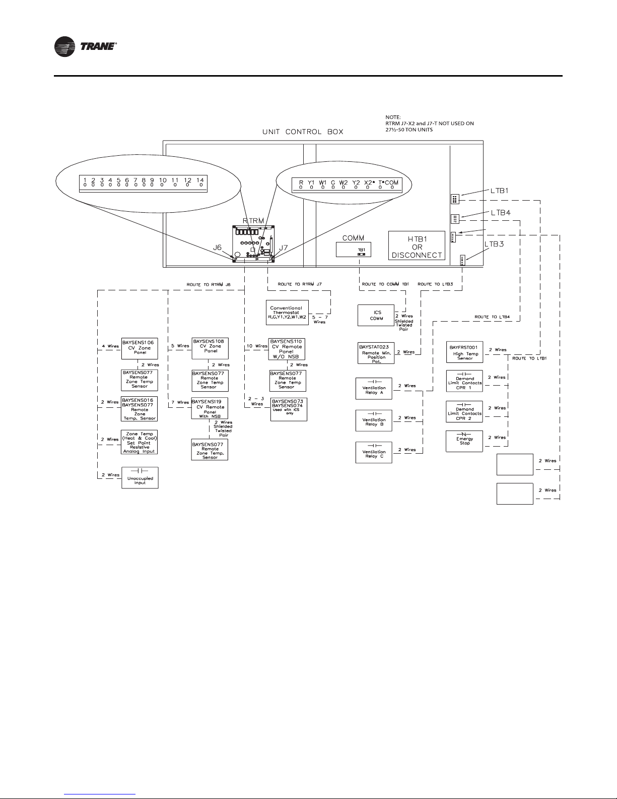
Installation Electrical
LT B6
Space
Humidity
Sensor
Space
Humidistat
RTRM J7 Thermostat Inputs N/A for SZ VAV
Figure 19. Typical field wiring requirements for CV and SZ VAV control options
30 RT-SVX34F-EN
 Loading...