


 Loading...
Applications
Engineering Manual
Chiller System Design and
Control
May 2009
SYS-APM001-EN

Chiller System Design
and Control
Susanna Hanson, applications engineer
Mick Schwedler, applications manager
Beth Bakkum, information designer

Preface
This manual examines chilled-water-system components, configurations, options, and control strategies. The goal is to provide system designers with options they can use to satisfy the building owners’ desires, but this manual is not intended to be a complete chiller-system design manual.
System designers may get the most use from this manual by familiarizing themselves with chilled-water-system basics and understanding the benefits of various options. Thereafter, when a specific job will benefit from these advantages, consult appropriate sections of the manual in detail.
The Engineers Newsletters that are referenced in this manual are available at: www.trane.com/commercial/library/newsletters.asp
Trane, in proposing these system design and application concepts, assumes no responsibility for the performance or desirability of any resulting system design. Design of the HVAC system is the prerogative and responsibility of the engineering professional.
“Trane” and the Trane logo are registered trademarks, and TRACE, System Analyzer and TAP are trademarks of Trane, a business of Ingersoll-Rand.
© 2009 Trane All rights reserved |
Chiller System Design and Control |
SYS-APM001-EN |

Contents
Preface .................................................................................................. |
i |
Primary System Components ................................................... |
1 |
Chiller ............................................................................................... |
1 |
Loads ................................................................................................ |
7 |
Chilled-Water Distribution System .................................................. |
10 |
Condenser-Water System ................................................................ |
13 |
Unit-Level Controls .......................................................................... |
15 |
Application Considerations ...................................................... |
18 |
Small Chilled-Water Systems (1-2 chillers) ...................................... |
18 |
Mid-Sized Chilled-Water Systems (3-5 Chillers) ............................. |
21 |
Large Chilled-Water Systems (6+ Chillers, District Cooling) .......... |
22 |
Chiller Plant System Performance ................................................. |
24 |
System Design Options ............................................................ |
27 |
Condenser-Water Temperatures ..................................................... |
29 |
Chilledand Condenser-Water Flow Rates ..................................... |
29 |
Cost Implications ............................................................................ |
38 |
Misconceptions about Low-Flow Rates ......................................... |
39 |
System Configurations .............................................................. |
42 |
Parallel Chillers ............................................................................... |
42 |
Series Chillers ................................................................................ |
44 |
Primary–Secondary (Decoupled) Systems ..................................... |
45 |
Variable-Primary-Flow Systems ...................................................... |
55 |
Chilled-Water System Variations ........................................... |
70 |
Heat Recovery ................................................................................ |
70 |
Condenser “Free Cooling” or Water Economizer .......................... |
70 |
Preferential Loading ........................................................................ |
73 |
Series–Counterflow Application ..................................................... |
77 |
Unequal Chiller Sizing ..................................................................... |
78 |
System Issues and Challenges ............................................... |
79 |
Low T Syndrome .......................................................................... |
79 |
Amount of Fluid in the Loop ........................................................... |
79 |
Contingency ................................................................................... |
81 |
Alternative Energy Sources ............................................................ |
82 |
Plant Expansion .............................................................................. |
83 |
Retrofit Opportunities ..................................................................... |
84 |
Applications Outside the Chiller’s Range ....................................... |
84 |
SYS-APM001-EN |
Chiller System Design and Control |
iii |

System Controls ........................................................................... |
87 |
Chilled-Water System Control ........................................................ |
87 |
Condenser-Water System Control .................................................. |
89 |
Failure Recovery ............................................................................. |
95 |
Conclusion ...................................................................................... |
96 |
Glossary ........................................................................................... |
97 |
References ..................................................................................... |
100 |
Index ................................................................................................ |
103 |
iv |
Chiller System Design and Control |
SYS-APM001-EN |

For more details on the basic operation and components of a chilled-water system, consult another Trane publication, Chilled-Water Systems, part of the Air Conditioning Clinic Systems Series (TRG-TRC016-EN).
Primary System Components
Chilled-water systems consist of these functional parts:
•Chillers that cool the water or fluid
•Loads, often satisfied by coils, that transfer heat from air to water
•Chilled-water distribution pumps and pipes that send chilled water to the loads
•Condenser-water pumps, pipes, and cooling towers or condenser fans that reject heat from the chiller to ambient air
•Controls that coordinate the operation of the mechanical components together as a system
In most cases, the chiller’s purpose is to make water colder. Some chillers cool a mixture of water and other chemicals, most commonly added to prevent freezing in low-temperature applications. Other additives may be used to modify the properties of the fluid, thereby making it more suitable for its intended application. For the purposes of this manual, the term water can be understood to be any such acceptable fluid, with recognition of the diverse applications in which chillers are used.
The chiller rejects the heat extracted from the chilled water, plus the heat of compression (in the vapor-compression cycle), or the heat of absorption (in the case of an absorption chiller) to either the ambient air (air-cooled) or to another circuit of water (water-cooled). If the compressor-motor is refrigerant cooled, the chiller also rejects heat generated by motor inefficiency. Air-cooled condensers use fans to facilitate cooling by the ambient air. Water-cooled condensers typically use an evaporative cooling tower.
After the water has been chilled, it is distributed via pumps, pipes, and valves (the distribution system) to the loads, where a heat exchanger—for example, a cooling coil in an air-handler—transfers heat from the air to the chilled water, which is returned to the chiller.
Each component of the chilled-water system is explained in more detail in the following sections.
Specific application considerations for absorption chillers are addressed in another Trane publication, Absorption Chiller System Design (SYS-AM-13).
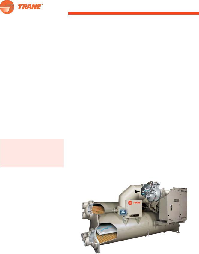
Chiller
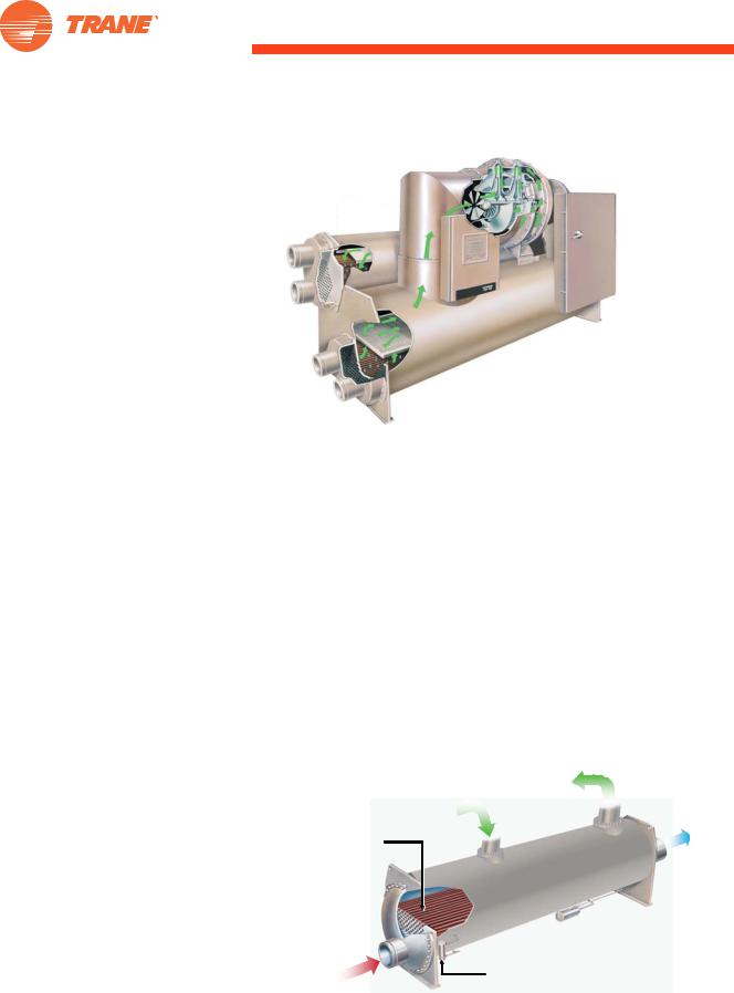
There are a variety of water chiller types. Most commonly, they are absorption, centrifugal, helical rotary, and scroll. Some reciprocating chillers are also available. Chillers can be either airor water-cooled. Major vapor-compression chiller components include an evaporator, compressor(s), condenser, and expansion device(s) (Figure 1). This manual discusses the chiller’s evaporator and condenser and their relationship to the chilled-water system.
SYS-APM001-EN |
Chiller System Design and Control |
1 |
Primary System Components
Figure 1. Typical vapor-compression chiller
Compressor
Condenser
Evaporator
Water-cooled chillers are typically installed indoors; air-cooled chillers are typically installed outdoors—either on the roof or next to the building. In cold climates, air-cooled chillers may have a remote evaporator inside the building for freeze protection.
Chiller evaporator
The evaporator section of a water chiller is a shell-and-tube, refrigerant-to- water heat exchanger. Depending on the chiller’s design, either the refrigerant or the water is contained within the tubes.
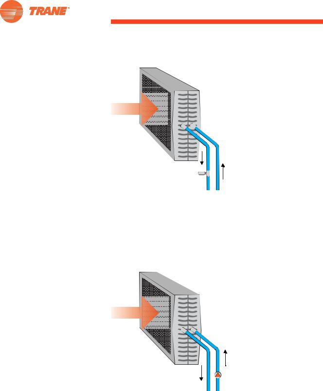
•In a flooded shell-and-tube evaporator (Figure 2), cool, liquid refrigerant at low pressure enters the distribution system inside the shell and moves uniformly over the tubes, absorbing heat from warmer water that flows through the tubes.
Figure 2. Flooded evaporator cut-away |
|
|
|
Refrigerant |
|
|
Vapor |
|
Liquid |
Chilled |
|
Refrigerant |
||
Water |
||
Tube Bundle |
||
Supply |
Chilled |
Liquid Level |
|
Water |
||
Sensor |
||
Return |
||
|
2 |
Chiller System Design and Control |
SYS-APM001-EN |
Primary System Components
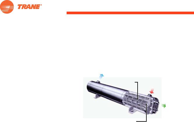
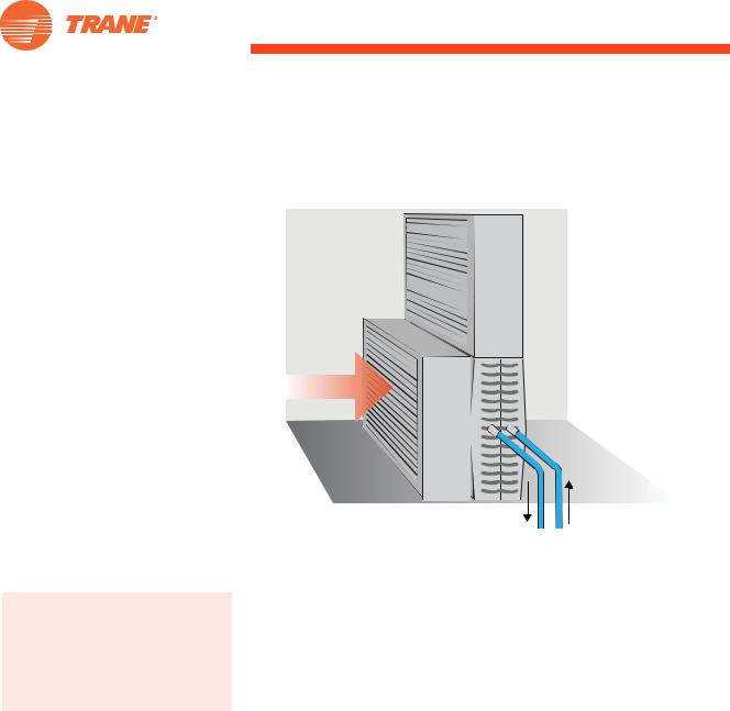
•In a direct-expansion (DX) shell-and-tube evaporator (Figure 3), warmer water fills the shell while the cool, lower-pressure liquid refrigerant flows through the tubes.
Figure 3. Direct-expansion evaporator cut-away
Chilled Water
Supply
Chilled
Baffles Water
Return
Refrigerant
Vapor
 Liquid
Refrigerant
Tube Bundle
In either design, there is an approach temperature, which is the temperature difference between the refrigerant and exit water stream temperatures. The approach temperature is a measure of the heat transfer efficiency of the evaporator.
Effect of chilled-water temperature
For a given chiller, as the leaving chilled-water temperature drops, the refrigerant temperature and pressure must also drop. Conversely, as the leaving chilled-water temperature rises, so do the refrigerant temperature and pressure. When the leaving chilled-water temperature changes, the work a compressor must do also changes. The effect of leaving chilled-water temperature change on power consumption can be 1.0 to 2.2 percent per degree Fahrenheit [1.8 to 4.0 percent per degree Celsius]. Always consider the energy consumption of the entire system—not only the chiller. It is important to remember that although reducing leaving chilled-water temperature penalizes the chiller, it may reduce the overall system energy because less water is pumped through the system. System interactions are covered in more detail in “System Design Options” on page 27.
Effect of chilled-water flow rate and variation
The evaporator is sensitive to the water flow rate. Excessive flow may result in high water velocity, erosion, vibration, or noise. Insufficient flow reduces heat-transfer efficiency and causes poor chiller performance, which might cause the chiller controls to invoke safeties. Some designers have concerns over low flow rates causing fouling. Generally, as Webb and Li1 noted, these concerns are unwarranted since the chilled-water loop is a closed system, thus reducing the chances of materials entering the system and causing fouling. Chilled-water flow through the evaporator must be kept within specific minimum and maximum limits. Contact the manufacturer for these limits.
SYS-APM001-EN Chiller System Design and Control 3

Primary System Components
Some chiller controls can accommodate very little flow variation during machine operation.2 Other, more sophisticated, chiller controls allow some flow variation. Some chillers can tolerate flow-rate variations—as much as 50 percent per minute or greater—while others can only tolerate up to 2 percent per minute. It is important that chiller capabilities are matched to system requirements. Contact the chiller manufacturer to determine the allowable rate of flow variation before varying the flow through the evaporator in a chiller. Flow variation is discussed in detail in the section “Variable-Primary- Flow Systems” on page 55.
Water-cooled condenser
To cool a building or process, the transferred heat must ultimately be rejected outdoors or to another system (heat recovery). The total amount of heat rejected includes the sum of the evaporator load, the compressor work, and the motor inefficiency. In a hermetic chiller, where the motor and compressor are in the same housing, these loads are all rejected through the condenser. In an open chiller, where the motor is separate from the compressor and connected by a shaft, the motor heat is rejected directly to the surrounding air. The evaporator load and the compressor work are rejected through the condenser, and the motor heat must be taken care of by the equipment room’s air-conditioning system.
Effect of condenser-water temperature
For a given chiller, as the leaving condenser-water temperature rises, refrigerant temperature and pressure also rise. Conversely, as the leaving condenser-water temperature drops, so do refrigerant temperature and pressure. As the refrigerant pressure and temperature changes, the work a compressor must do also changes. The effect of leaving-condenser-water temperature change on power consumption can be 1.0 to 2.2 percent per degree Fahrenheit [1.8 to 4.0 percent per degree Celsius]. Always consider the energy consumption of the entire system—not just the chiller. It is important to remember that although raising the leaving condenser-water temperature penalizes the chiller energy, it may reduce the energy used by the condenser pumps and cooling tower through the use of reduced flow rates and higher thermal driving-forces on the tower. System interactions are covered in more detail in “System Design Options” beginning on page 27.
Effect of condenser-water flow rate
The condenser is sensitive to the water flow rate. Excessive flow may result in high water velocity, erosion, vibration, or noise, while insufficient flow reduces heat transfer efficiency and causes poor chiller performance. Therefore, condenser-water flow through the chiller should be kept within a specific range of limits, except during transient startup conditions. Contact the manufacturer for these limits. Some chillers may allow extended operation below the selected flow rates.
If water velocity through the condenser tubes is too low for significant periods of time and the water is extremely hard, long-term fouling of the tubes may also occur. Webb and Li1 tested a number of internally-enhanced condenser tubes at low velocity (3.51 ft/s [1.07 m/s]) and high water hardness.
4 Chiller System Design and Control SYS-APM001-EN
Primary System Components
Packaged or Split System?
A number of different options are available for packaging and splitting the components of an air-cooled chiller. There is an excellent discussion in Chilled-Water Systems, part of the Air Conditioning Clinic Systems Series (TRG-TRC016-EN).
While they found that some of the internally-enhanced tubes fouled in the long term, they concluded:
Because of the high hardness and low water velocity used in these tests, we do not believe that the fouling experienced is typical of that expected in commercial installations. With use of good maintenance practices and water quality control, all of the tubes tested are probably suitable for long-term-fouling applications.
It is important to remember that a chiller selected for low flow does not necessarily have low velocity through its tubes, as discussed in the chapter “System Design Options” on page 27. If tube fouling is a major concern, consider the use of smooth, rather than internally-enhanced, tubes in the condenser for ease of cleaning.
Air-cooled condenser
Air-cooled chillers do not use condenser-water, since they reject their heat by passing ambient air across refrigerant-to-air heat exchangers. In packaged air-cooled chillers, the manufacturers improve performance by staging fans in response to chiller load and ambient, dry-bulb temperature. Air-cooled chillers can also be split apart. One technique is to use an indoor remote evaporator with a packaged air-cooled condensing unit outdoors. Another technique is to locate the compressor(s) and the evaporator indoors (also known as a condenserless chiller) with an air-cooled condenser outdoors. It is also possible to have an indoor air-cooled condenser.
Air-cooled versus water-cooled condensers
One of the most distinctive differences in chiller heat exchangers continues to be the type of condenser selected—air-cooled versus water-cooled. When comparing air-cooled and water-cooled chillers, available capacity is the first distinguishing characteristic. Air-cooled condensers are typically available in packaged chillers ranging from 7.5 to 500 tons [25 to 1,580 kW]. Packaged water-cooled chillers are typically available from 10 to nearly 4,000 tons [35 to 14,000 kW].
Maintenance
A major advantage of using an air-cooled chiller is the elimination of the cooling tower. This eliminates the concerns and maintenance requirements associated with water treatment, chiller condenser-tube cleaning, tower mechanical maintenance, freeze protection, and the availability and quality of makeup water. This reduced maintenance requirement is particularly attractive to building owners because it can substantially reduce operating costs. However, see “Energy efficiency” below.
Systems that use an open cooling tower must have a water treatment program. Lack of tower-water treatment results in contaminants such as bacteria and algae. Fouled or corroded tubes can reduce chiller efficiency and lead to premature equipment failure.
SYS-APM001-EN |
Chiller System Design and Control |
5 |

Primary System Components
Low-ambient operation
Air-cooled chillers are often selected for use in systems with year-round cooling requirements that cannot be met with an airside economizer. Aircooled condensers have the ability to operate in below-freezing weather, and can do so without the problems associated with operating the cooling tower in these conditions. Cooling towers may require special control sequences, basin heaters, or an indoor sump for safe operation in freezing weather.
For process applications, such as computer centers that require cooling yearround, this ability alone often dictates the use of air-cooled chillers.
Energy efficiency
Water-cooled chillers are typically more energy efficient than air-cooled chillers. The refrigerant condensing temperature in an air-cooled chiller is dependent on the ambient dry-bulb temperature. The condensing temperature in a water-cooled chiller is dependent on the condenser-water temperature, which is dependent on the ambient wet-bulb temperature. Since the design wet-bulb temperature is often significantly lower than the dry-bulb temperature, the refrigerant condensing temperature (and pressure) in a water-cooled chiller can be lower than in an air-cooled chiller. For example, at an outdoor design condition of 95°F [35°C] dry-bulb temperature, 78°F [25.6°C] wet-bulb temperature, a cooling tower delivers 85°F [29.4°C] water to the water-cooled condenser. This results in a refrigerant condensing temperature of approximately 100°F [37.8°C]. At these same outdoor conditions, the refrigerant condensing temperature in an air-cooled condenser is approximately 125°F [51.7°C]. A lower condensing temperature, and therefore a lower condensing pressure, means that the compressor needs to do less work and consumes less energy.
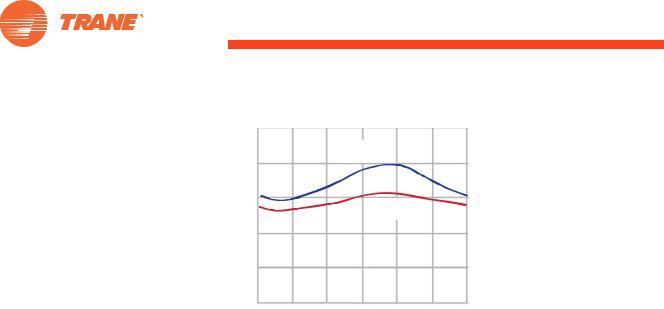
This efficiency advantage may lessen at part-load conditions because the drybulb temperature tends to drop faster than the wet-bulb temperature (see Figure 4). As a result, the air-cooled chiller may benefit from greater condenser relief. Additionally, the efficiency advantage of a water-cooled chiller is much less when the additional cooling tower and condenser pump energy costs are considered. Performing a comprehensive energy analysis is the best method of estimating the operating-cost difference between aircooled and water-cooled systems.
6 |
Chiller System Design and Control |
SYS-APM001-EN |
Primary System Components
Figure 4. Air-cooled or water-cooled efficiency
Outdoor Temperature
1212 Midnight
midnight
Dry Bulb
dry bulb
wetWetbulbBulb
12 |
12 |
12 |
12 |
Noon |
Midnight |
|
midnight |
Another advantage of an air-cooled chiller is its delivery as a “packaged system.” Reduced design time, simplified installation, higher reliability, and single-source responsibility are all factors that make the factory packaging of the condenser, compressor, and evaporator a major benefit. A water-cooled chiller has the additional requirements of condenser-water piping, pump, cooling tower, and associated controls.
Water-cooled chillers typically last longer than air-cooled chillers. This difference is due to the fact that the air-cooled chiller is installed outdoors, whereas the water-cooled chiller is installed indoors. Also, using water as the condensing fluid allows the water-cooled chiller to operate at lower pressures than the air-cooled chiller. In general, air-cooled chillers last 15 to 20 years, while water-cooled chillers last 20 to 30 years.
To summarize the comparison of air-cooled and water-cooled chillers, aircooled chiller advantages include lower maintenance costs, a pre-packaged system for easier design and installation, and better low-ambient operation. Water-cooled chiller advantages include greater energy efficiency (at least at design conditions) and longer equipment life.
Loads
In comfort-cooling applications, cooling loads are often satisfied by air handlers equipped with coils to transfer heat from the conditioned space air to circulating chilled-water. Air is cooled and dehumidified as it passes across the finned surface of the cooling coils. Since the psychrometric process of conditioning air takes place at the coils, selection of the optimum coil size and type from the wide variety available is important for proper system performance.
Some specialized process loads do not involve cooling air. Instead, they may involve heat transfer directly within a piece of process equipment, such as the cooling jacket of an injection-molding machine.
SYS-APM001-EN |
Chiller System Design and Control |
7 |
Primary System Components
Heat transferred from the loads can be controlled in a number of ways:
•Three-way valve
•Two-way valve
•Variable-speed pump
•Face-and-bypass dampers
Three-way valve load control
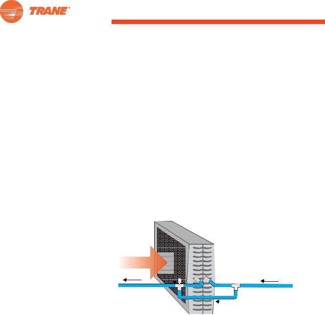
A three-way control valve (Figure 5) regulates the amount of water passing through a coil in response to loads. The valve bypasses unused water around the coil and requires a constant flow of water in the system, regardless of load. A drawback of this bypass is that the temperature of the water leaving the three-way valve is reduced at part-load conditions. This can be a major contributor to so-called “low T syndrome” discussed on page 79. Three-way valves are used in many existing systems, especially in those with constantvolume pumping.
Figure 5. Three-way valve
Airflow
Three-Way |
|
Bypass |
Modulating |
|
|
|
Pipe |
|
Valve |
|
|
|
|
Two-way valve load control
A two-way, water modulating valve (Figure 6) at the coil performs the same water throttling function as the three-way valve. The coil sees no difference between these two methods. The chilled-water system, however, sees a great difference. In the case of the two-way valve, all flow in the coil circuit is throttled. No water is bypassed. Consequently, a system using two-way valves is a variable-flow chilled-water system. The temperature of the water leaving the coil is not diluted by bypass water so at part-load conditions, the system return-water temperature is higher than with three-way valve control.
8 |
Chiller System Design and Control |
SYS-APM001-EN |
Primary System Components
Figure 6. Two-way valve
Airflow
Two-Way
Modulating
Valve
Variable-speed pump load control
By using a pump for each coil (Figure 7), the flow may be controlled by varying the pump speed. In such systems, there may be no control valves at the coil. This can reduce both the valve and the valve installation costs, but increases coil pump and maintenance costs.
Figure 7. Variable-speed pump load control
Airflow
Variable
Speed Pump
Face-and-bypass dampers
Figure 8 shows a control variation using an uncontrolled or “wild” coil. In this system, control of the conditioned air supply is executed by face-and- bypass dampers that permit a portion of the air to bypass the coil surface. Advantages of this strategy are the elimination of control valves and improved part-load dehumidification. A disadvantage is that all the water is
SYS-APM001-EN |
Chiller System Design and Control |
9 |
Primary System Components
pumped all the time; however, in systems with very small water pressure drops, this system arrangement may work economically.
Figure 8. Uncontrolled water flow with bypass damper
Bypass
Damper
Airflow
Face
Damper
Additional reference information on the components of a chilled-water distribution system is available in the
2008 ASHRAE HVAC Systems and Equipment Handbook, chapter 12, “Hydronic Heating and Cooling System Design.” 3
Chilled-Water Distribution System
Chilled water is circulated through fixed piping—most commonly steel, copper, or plastic—that connects the chiller with various load terminals. Piping is sized to meet pressure loss, water velocity, and construction cost parameters.
Chilled-water pump
The chilled-water pump creates pressure to circulate chilled water within the loop. Generally, the pump must overcome the frictional pressure losses caused by the piping, coils, and chiller and the pressure differential across open control valves in the system. The pump, while working at the system static pressure, does not need to overcome this static pressure. For example, in a forty-story building, the pump need not overcome the static pressure due to those forty stories.
The chilled-water pump is typically located upstream of the chiller; however, it may be anywhere in the system, provided that the pump:
•meets the minimum pump net positive suction-head requirements. That is, the system pressure at the pump inlet must be both positive and high enough to allow the pump to operate properly;
•maintains the minimum dynamic pressure head at critical system components (usually the chiller). If the dynamic pressure head is not high enough at these components, proper flow will not be established through them;
10 |
Chiller System Design and Control |
SYS-APM001-EN |
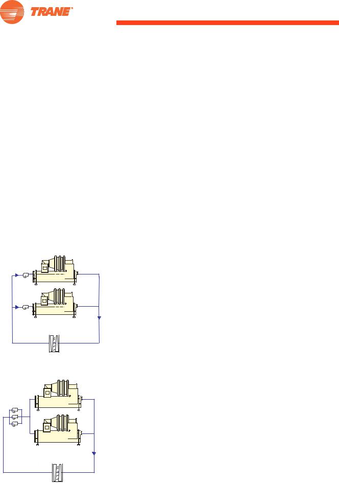
Figure 9. Pump per chiller
Pump
Pump
Load
Figure 10. Manifolded pumps
Manifolded |
Pumps |
Load
SYS-APM001-EN
Primary System Components
•accommodates the total pressure (static head plus dynamic head) on system components such as the chiller’s evaporator, valves, etc.
Note that the pump heat is added to the water and must be absorbed by the chiller. Generally, this represents a very small temperature increase.
Multiple pumps are often used for redundancy. Depending on the terminal control devices and system configurations, the chilled-water pumps may be either constantor variable-flow.
As previously stated, pumps may be either on the inlet or the outlet of the chiller, as long as the inlet of the pump experiences an adequate, positive suction pressure. In applications where there is a significant liquid column head (for example, a high-rise building), the pump is often located at the chiller’s outlet so that the evaporator bundle is subject only to the static head (rather than the static head plus the dynamic head added by the pump). The need for high-pressure water boxes on the chiller can be eliminated.
Conversely, an advantage of locating the pump at the chiller’s inlet is that if the pump motor rejects its heat to the water, the heat can be removed directly by the chiller. The chiller does not need to compensate for the pump heat by making colder water.
Pump per chiller
In either a primary–secondary or variable-primary-flow system, using one pump per chiller simplifies system hydraulics (Figure 9). The pump can be selected to produce the flow and pressure drop necessary for the specific chiller. Bringing on additional pumps changes system hydraulics, but only minimally. One drawback of such a system is a lack of redundancy, since the pump and chiller are dedicated to one another. This may be overcome by using a spare pump, pipes, and valves so that the spare pump could work with any chiller during emergency conditions.
Manifolded pumps
In an effort to resolve the redundancy consideration, some designers prefer to manifold pumps and provide n+1 pumps, where n is the number of chillers (Figure 10). Such an arrangement allows any pump to be used with any chiller. However, system hydraulics become more complicated. Unless all piping runs and evaporator pressure drops are equal, the amount of water flowing to each chiller will differ. As discussed in “Moderate ’low T syndrome’" on page 68, manifolded pumps present a control opportunity when low T is experienced.
Either pump configuration can be successful; one pump per chiller simplifies the hydraulics, while manifolded pumps allow redundancy.
Distribution piping
By itself, the distribution system is easy to understand. Figure 11 shows a simplified distribution system consisting of multiple cooling coils, each controlled by a thermostat that regulates the flow in its respective coil. The
Chiller System Design and Control |
11 |
Primary System Components
valves may be either three-way or two-way. As previously discussed, threeway valves require constant water flow, while two-way valves allow the water flow in the system to vary. As flow varies, the pump may simply ride its curve or use a method of flow control such as a variable-speed drive. Refer to the chapter “System Configurations” on page 42 for a detailed discussion of distribution-system options.
Figure 11. Simplified distribution system
Expansion
Tank
Pump
Chiller
Distribution
Piping
Loads
Figure 12. Constant flow system
CV
Pump
Chillers
Three-Way
Control
Valve
Load
The distribution system may contain other components, such as an expansion tank, control valves, balancing valves, check valves, and an air separator, to name a few. The density, and therefore the volume, of the water in a “closed” chilled-water distribution system varies as it undergoes changes in temperature. The expansion tank allows for this expansion and contraction of water volume.
Pumping arrangements
Variations on three basic pumping arrangements are common. They are referred to as constant flow, primary-secondary (decoupled) flow, and variable-primary flow (VPF). The implications and nuances of each of these is discussed in greater detail in “System Configurations” on page 42.
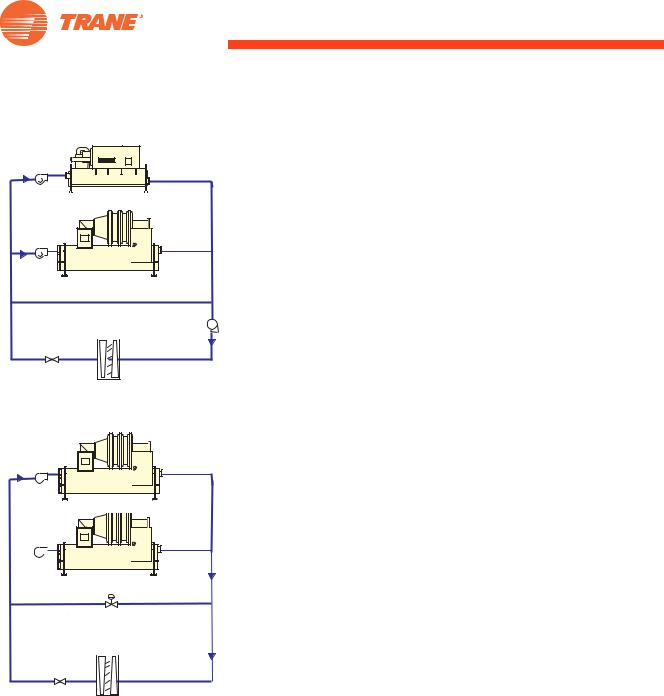
Constant flow system
When a chiller is on, a constant speed pump dedicated to it is on, and there need not be any other pumps operated in the system (Figure 12). This is a simple system and makes the most sense when there will only be one chiller operated at a time in the system. Challenges with this system arise at part load when chillers are in the parallel arrangement (refer to “Parallel Chillers” on page 42). To solve some of these problems, the chillers can be placed in
12 |
Chiller System Design and Control |
SYS-APM001-EN |
Primary System Components
Figure 13. Primary-secondary system
CV
Pump
the series, or another pumping arrangement can be considered. Reducing the flow rate affects this system type’s energy use all the time, so careful attention to flow rates and temperature is critical (refer to “System Design Options” on page 27).
Chillers |
|
CV |
|
Pump |
|
Bypass (Decoupler) |
|
Two-Way |
VV |
Control |
Pump |
Valve |
|
Load |
|
~
Primary-secondary system
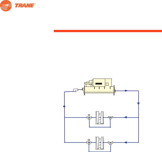
In this configuration (Figure 13), the distribution piping is decoupled from the chiller piping and is known as the primary-secondary or decoupled system. There is constant primary flow through the operating chiller(s) and variable secondary flow through the loads. A bypass pipe between the two balances the primary flow with the secondary flow. Because there are more pumps and a bypass, this system costs more than a constant flow system to install. Details on this system type are in “Primary–Secondary (Decoupled) Systems” on page 45.
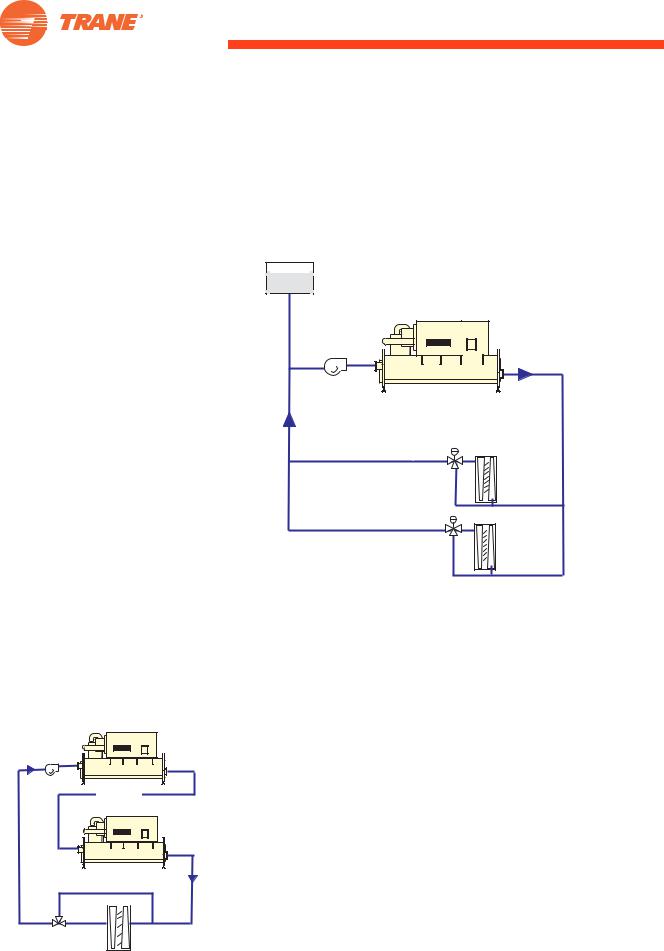
Variable-primary system
Figure 14. Variable-primary system
VV |
Pump |
~ |
Chillers |
VV Pump
 ~
~
This pumping arrangement (Figure 14) was made possible in recent years by advanced chiller controls that permit varying the flow through the chillers. Like a constant flow system, the distribution piping is directly connected to the chiller piping. Flow is varied through at least most of the loads and the chillers. A smaller bypass (compared to the primary-secondary system) ensures chiller minimum flow rates are avoided. Fewer pumps and smaller bypass lead to lower first costs compared to the primary-secondary system. Operation costs can also be lower, but the plant is controlled differently than in other pumping arrangements and operator training is essential. This system type is covered in detail in “Variable-Primary-Flow Systems” on page 55.
Minimum Flow Bypass Valve
Two-Way
Control
Valve
Load
SYS-APM001-EN
Condenser-Water System
As in chilled-water distribution systems, condenser-water system piping— most commonly steel, copper, or plastic—is sized to meet a project’s operating pressure, pressure loss, water velocity, and construction cost parameters. Pressure drop through piping and the chiller’s condenser, plus the cooling tower static lift, is overcome by use of a condenser-water pump.
To ensure optimum heat transfer performance, the condenser-heat transfer surfaces must be kept free of scale and sludge. Even a thin deposit of scale can substantially reduce heat transfer capacity and chiller efficiency. Specifics of cooling-tower-water treatment are not discussed in this manual. Engage the services of a qualified water treatment specialist to determine the level of water treatment required to remove contaminants from the cooling tower water.
Cooling tower
To reject heat, water is passed through a cooling tower where a portion of it evaporates, thus cooling the remaining water. A particular cooling tower’s effectiveness at transferring heat depends on water flow rate, water temperature, and ambient wet bulb. The temperature difference between the
Chiller System Design and Control |
13 |
Primary System Components
Figure 15. Manifolded condenserwater pumps
Cooling
Towers
Manifolded
Pumps
Chillers
water entering and leaving the cooling tower is the range. The temperature difference between the leaving water temperature and the entering wet-bulb temperature is the approach.
Effect of load on cooling tower performance
As the building load—or heat rejection—decreases, range and approach also decrease. This means that when the building is at part load, the cooling tower can provide colder water at the same ambient wet-bulb temperature.
Effect of ambient conditions on cooling tower performance
As ambient wet-bulb temperature drops, the approach—at a constant load— increases. This is counter-intuitive to many, and it must be considered when cooling-tower-control strategies are developed. Detailed descriptions of these conditions appear in “Chiller–tower energy balance” on page 91. For additional information, refer to 2008 ASHRAE HVAC Systems and Equipment Handbook, chapter 39, “Cooling Towers.” 3
Condenser-water pumping arrangements
Water-cooled chillers require condenser-water-system variations to be considered. For a discussion of condenser-water temperatures and flow rates, refer to “System Design Options” on page 27. Since air-cooled-chiller condenser controls are part of the chiller design, they are not discussed in this manual.
Most important, the inlet to the pump must have sufficient net positive head. This often means locating the pump below the cooling-tower sump.
Single tower per chiller
In some applications each chiller has a dedicated cooling tower. This is most likely to occur when chillers, and their accompanying towers, are purchased at different times during the facility’s life—such as when additions are made.
Manifolded pumps
A much-used pumping arrangement has a single cooling-tower sump with manifolded pumps, one condenser water line, and separate, smaller, pipes for each chiller as shown in Figure 15. This provides a number of advantages:
•Pumping redundancy
•If cooling towers cells can be isolated, any cooling-tower cell can run with any chiller.
•Hydraulics are generally less problematic than on the chilled-water side.
•Cooling towers can be located remotely from chillers, with only a single supply and return pipe to connect them.
14 |
Chiller System Design and Control |
SYS-APM001-EN |
Primary System Components
Unit-Level Controls
The chilled-water supply temperature is usually controlled by the chiller. Most commonly, supply water temperature is used as the sensed variable to permit control of chiller capacity to meet system load demand. Supplytemperature control strategies may be used on either constantor variableflow systems. As previously discussed, flow control is executed at the load terminals using three-way or two-way valves, or separate pumps for each coil. Control capabilities run the gamut from slow-acting pneumatic controls, to electromechanical controls, to sophisticated digital controls that use "feedforward" algorithms tuned to give superior performance.
Chiller control
Today’s chiller controls are capable of doing more than simply turning the chiller on and off. At a minimum, these controls should monitor:
•Safety points, such as bearing temperatures and electrical points, that may cause motor failure when out of range.
•Data points that may cause operational problems if corrective action is not taken. An example is low chilled-water or refrigerant temperature, which may result in freezing in or around the evaporator tubes.
•General points to ensure proper chiller performance and refrigerant containment.
Table 1. Recommended chiller-monitoring points per ASHRAE Standard 1474
|
Flow |
|
|
|
|
|
Inlet Pressure |
|
Chilled Water (or other |
|
|
Inlet Temperature |
||
secondary coolant) |
|
|
Outlet Pressure |
||
|
||
|
|
|
|
Outlet Temperature |
|
|
|
|
Evaporator |
Refrigerant Pressure |
|
|
||
Refrigerant Temp. |
||
|
||
|
|
|
|
Level |
|
|
|
|
Oil |
Pressure |
|
|
||
|
Temperature |
|
|
|
|
|
Addition of |
|
|
|
|
Vibration Levels |
|
|
|
|
|
|
Exhaust Time |
|
Purge |
|
|
Discharge Count |
||
|
||
|
|
|
|
Dry Bulb |
|
Ambient Temperatures |
|
|
Wet Bulb |
||
|
|
Flow |
|
|
|
|
|
Inlet Pressure |
|
Condenser |
|
|
Inlet Temperature |
||
Water |
|
|
Outlet Pressure |
||
|
||
|
|
|
|
Outlet Temperature |
|
|
|
|
Condenser |
Refrigerant Pressure |
|
|
||
Refrigerant Temp. |
||
|
||
|
|
|
|
Level |
|
|
|
|
|
Compressor Discharge Temp. |
|
Refrigerant |
|
|
Compressor Suction Temp. |
||
|
|
|
|
Addition of (in Refrigerant Log) |
|
|
|
|
|
PPM Refrigerant Monitor Level |
|
|
|
|
|
Date and Time Data |
|
Logs |
|
|
Signature of Reviewer |
||
|
||
|
|
|
|
Amperes Per Phase |
|
Motor |
|
|
Volts Per Phase |
||
|
SYS-APM001-EN |
Chiller System Design and Control |
15 |
Primary System Components
For more information about chillers, Trane Air Conditioning Clinics are available for centrifugal (TRG-TRC010- EN), absorption (TRG-TRC011-EN) and helical-rotary (TRG-TRC012-EN) chiller types.
In addition to monitoring data, it is vital that the chiller controls alert operators to possible problems. Diagnostic messages are necessary for the operator to respond to safety issues and data points that are outside normal operating ranges. While communicating these diagnostic messages is a requirement, some chiller controls include factory-installed programming that responds to the issue causing the diagnostic messages. For example, when the chilled-water temperature nears freezing, the chiller sends a diagnostic message and adapts its operation by reducing the compressor capacity, raising the chilled-water temperature to a safer condition.
Finally, the chiller controls should communicate with a system-level controller. There are many system aspects that are outside the chiller’s direct control, such as condenser-water temperature and the amount of fluid flowing through the evaporator and condenser. To minimize the system energy costs, the system controls must coordinate chiller, pump, coolingtower, and terminal-unit controls. This can only be done if adequate information is communicated from each system component to the systemlevel controls. System-level control is discussed in detail in “System Controls” beginning on page 87.
Centrifugal chiller capacity control
The capacity of a centrifugal chiller can be modulated using inlet guide vanes (IGV) or a combination of IGV and a variable-speed drive (adjustablefrequency drive, AFD)(Figure 16). Variable-speed drives are widely used with fans and pumps, and as a result of the advancement of microprocessor-based controls for chillers, they are being applied to centrifugal water chillers.
Figure 16. Centrifugal chiller with AFD |
|
||
|
Compressor |
|
|
Inlet Guide Vanes |
|
|
|
|
|
||
Condenser |
Adjustable |
||
|
|
|
|
|
|
|
Frequency |
|
|
|
Drive |
Evaporator
ASHRAE 90.1 requires a chiller to meet both full and part-load efficiency requirements. Using an AFD with a centrifugal chiller degrades the chiller’s full-load efficiency. This causes an increase in electricity demand or real-time pricing charges. At the time of peak cooling, such charges can be ten (or more) times the non-peak charges. In return, an AFD can offer energy savings
16 Chiller System Design and Control SYS-APM001-EN
Primary System Components
by reducing motor speed at “low-lift” conditions, when cooler condenser water is available.
Certain system characteristics favor the application of an AFD, including:
•A substantial number of part-load operating hours (for example, when an airor water-economizer is not installed in the system)
•The availability of cooler condenser water (condenser-water reset)
•Chilled-water reset control
Chiller savings using condenserand chilled-water-temperature reset, however, should be balanced against the increase in pumping and coolingtower energy. Performing a comprehensive energy analysis is the best method of determining whether an AFD is desirable. It is important to use actual utility costs, not a “combined” cost, for demand and consumption charges. It is also important to include drive maintenance and replacement costs, since the drive life is shorter than the chiller life. See “Energy and economic analysis of alternatives” on page 26.
Depending on the application, it may make sense to use the additional money that would be needed to purchase an AFD to purchase a more efficient chiller instead. This is especially true if demand charges are significant, or if the condenser water is close to its design temperature most of the time (e.g., in a hot and humid climate such as Miami).
Consider the following analysis of an 800-ton office building with two chillers. The analysis compares equally priced high efficiency or AFDequipped chillers, as one or both of the chillers. Utility costs for the combined or “blended” rate are $0.10 per kWh and for the actual rate are $12 per kW and $0.06 per kWh.
Simple paybacks using the combined rate analysis show almost no difference between the two options (Table 2). However, when utility costs with an actual consumption and demand component are used, the difference between the alternatives is much more pronounced. The conclusion is that using actual energy rates matters a great deal.
Table 2. Analysis of high-efficiency chiller options with combined vs actual rates
Simple paybacks, humid climate |
Combined rate |
Actual rate |
|
|
|
AFD on both chillers |
7.2 |
12.7 |
|
|
|
High efficiency on both chillers |
7.1 |
8.3 |
|
|
|
AFD on one chiller |
6.1 |
10.8 |
|
|
|
High efficiency on one chiller |
6.3 |
7.7 |
|
|
|
SYS-APM001-EN |
Chiller System Design and Control |
17 |
Application Considerations
Chiller system size affects design and control considerations. Each size comes with its own set of advantages and challenges.
Small Chilled-Water Systems (1-2 chillers)
Figure 17. Small chilled-water system schematic
Pump
Air-Cooled Chiller
Control |
Load |
Valve |
|
A common design goal for the small chilled-water system with one or two chillers (Figure 17) is to minimize complexity while balancing energy consumption goals. Smaller chilled-water systems may have smaller budgets allotted for operation and maintenance and may run unattended more often than larger systems. Keeping it simple, while capitalizing on chilled water advantages, is the hallmark of a successful project.
The first cost of a small system is a common hurdle faced by a building owner. There are ways to minimize first costs without sacrificing operating costs. For example, a wider design T reduces flow rates, which in turn reduces pipe and pump sizes. In addition to reducing pump and pricing costs, this may also allow the designer to avoid installing a storage tank to meet the required chiller “loop times.” (See “Amount of Fluid in the Loop” on page 79.) On a system with multiple chillers, using a variable-primary-flow design (“Variable-Primary-Flow Systems” on page 55) can reduce the number of pumps, starters, electrical equipment, and space required.
18 |
Chiller System Design and Control |
SYS-APM001-EN |

Application Considerations
Constant flow
Constant flow is simple and often applied to small systems up to 200 tons— as long as the system pressure drop is fairly low and a wider T is applied to reduce the system flow rate. In constant flow systems, appropriate chilledwater reset reduces chiller energy. These two strategies for saving energy (reducing flow rates and/or chilled-water temperature reset) can be used successfully in the constant flow designs more common in small chilledwater systems. These two strategies are covered in “Selecting Chilledand Condenser-Water Temperatures and Flow Rates” on page 27 and “Chilled water reset—raising and lowering” on page 87.
Constant flow systems use either a balancing or pressure-reducing valve or, in a few cases, trim the pump impeller to set the system design flow. Pressure-reducing valves waste pump energy. Another option designers use to reduce pumping energy and increase system flexibility is to install a variable frequency drive on the pump motor and set it at a constant speed during system commissioning.
If, instead, system flow is balanced by trimming the pump impeller, flow adjustment is much more difficult. Using a variable frequency drive at a set speed allows the flow to be decreased or increased in the future if necessary. This approach is more cost effective because the cost of variable frequency drives has dropped. Any incremental cost will be offset by the elimination of the balancing valves and pump starter.
Variable flow
Although a variable-primary-flow system may cost more than a constant flow system, it is growing in popularity because it is less expensive than installing a decoupled system. Another reason for its increased popularity is that pump energy is reduced.
Some owners are concerned that the controls are more complex, but variable flow systems can work very simply in the small chilled-water system when there is only one chiller or when two chillers are piped in series. Key control issues for variable flow systems are discussed in “Variable-Primary-Flow Systems” on page 55, and variable flow with series chillers in “Series Chillers” on page 44.
Condensing method
Many small chilled-water systems use air-cooled chillers because of the lower maintenance requirements of the condensing circuit. Water-cooled systems are generally more energy efficient and have more options for features such as heat recovery, though some air-cooled chillers have partial heat recovery options.
To help the owner decide on the system selection, a comprehensive energy analysis is the best method of estimating the life cycle cost difference between air-cooled and water-cooled systems. Energy analysis is likely required for many facilities seeking LEED certification, so it may already be
SYS-APM001-EN Chiller System Design and Control 19

Application Considerations
part of those jobs. See “Energy and economic analysis of alternatives” on page 26.
Number of chillers
The number of chillers to install is a function of redundancy requirements and first cost. In general, the more chillers installed, the higher the initial cost. Therefore, many small systems only use one chiller. Most chillers in the 20 through 200 ton range use multiple compressors with multiple refrigeration circuits and provide a reasonable level of cooling redundancy. The only system controls installed on a single chiller installation may be a clock and ambient lockout switch to enable and disable the chilled-water system. If only one chiller is used, a system that varies the flow rate through the chiller can be quite simple to operate. Minimum and maximum flows and maximum rate of change for the flow would still need to be addressed (see “Variable- Primary-Flow Systems” on page 55).
As systems get larger, the owner may require more redundancy, leading them to install multiple chillers. Some designers use 200 tons as the maximum job size for a single chiller.
When there is more than one chiller, there are many more system control decisions to be made including:
• enabling the second chiller,
• turning the second chiller off, and
• failure recovery.
Two-chiller plants require higher system control intelligence than single chiller plants. Sequencing logic, discussed in “System Configurations” on page 42, varies based on system configuration, and failure recovery is discussed on page 95.
Parallel or series
Parallel configurations are more common than series configurations. (See “Parallel Chillers” on page 42.) In chiller systems with an even number of chillers, there are advantages to putting them into a series configuration, especially if low or variable water flow is desired. This offers the benefits of better system efficiency and higher capacity because the upstream chiller produces water at a warmer temperature. Series chillers should not be applied with low system Ts, because the maximum flow through the chillers may be reached. Efforts to eliminate the so-called “Low T syndrome” (page 79) must be addressed for both configurations. The energy and control requirements of series chillers are covered in “Series Chillers” on page 44.
Part load system operation
For small chilled-water systems, especially those with only one chiller, part load system energy use may be dominated by ancillary equipment, especially in a constant flow system. At low loads, constant speed pumps and tower fans constitute a much larger portion of the chiller plant energy
20 Chiller System Design and Control SYS-APM001-EN
Application Considerations
than at full load. Variable frequency drives for unloading tower fans and chilled-water pumps may provide benefits, depending on the costs, system operating hours, system type, and outdoor air conditions. (See “System Controls” on page 87.)
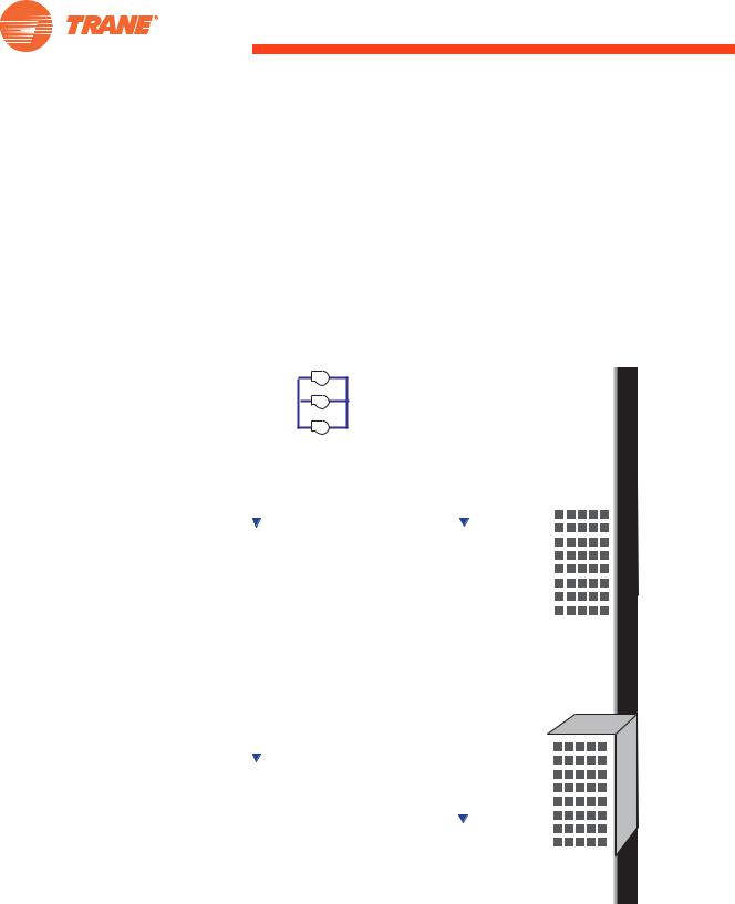
Mid-Sized Chilled-Water Systems
(3-5 Chillers)
Figure 18. Mid-sized chilled-water system schematic
Distribution Pumps
Loads
In addition to the design decisions faced by the small chilled-water system designer, the following objectives may be encountered by the mid-sized system designer.
Managing control complexity
As chilled-water systems get larger (Figure 18), control system design and execution become more critical and more complex. There are simply more combinations of equipment and operating scenarios. On the other hand, systems this size generally have more highly-skilled operators who can understand proper operation and maintenance. To help operators understand expected system operation, chiller plant controls are usually more customized and sophisticated.
Preferential vs. equalized loading and run-time
With more chillers, sequencing options might include preferentially loading the most efficient chiller or equalizing the run time of chillers. The decision hinges on how different these chillers are and the preferred maintenance routine. For example, a chiller plant with one quite old—though still reliable— chiller may periodically enable that chiller to ensure it continues to function,
SYS-APM001-EN |
Chiller System Design and Control |
21 |
Application Considerations
but use it sparingly due to its lower efficiency. Or, a chiller may have a different fuel source, used as a hedge against either high demand or high energy consumption charges for other energy sources. (See “Alternative Energy Sources” on page 82.) Some chilled-water systems have unequally sized chillers, allowing fewer chillers to operate. (See “Unequal Chiller Sizing” on page 78.)
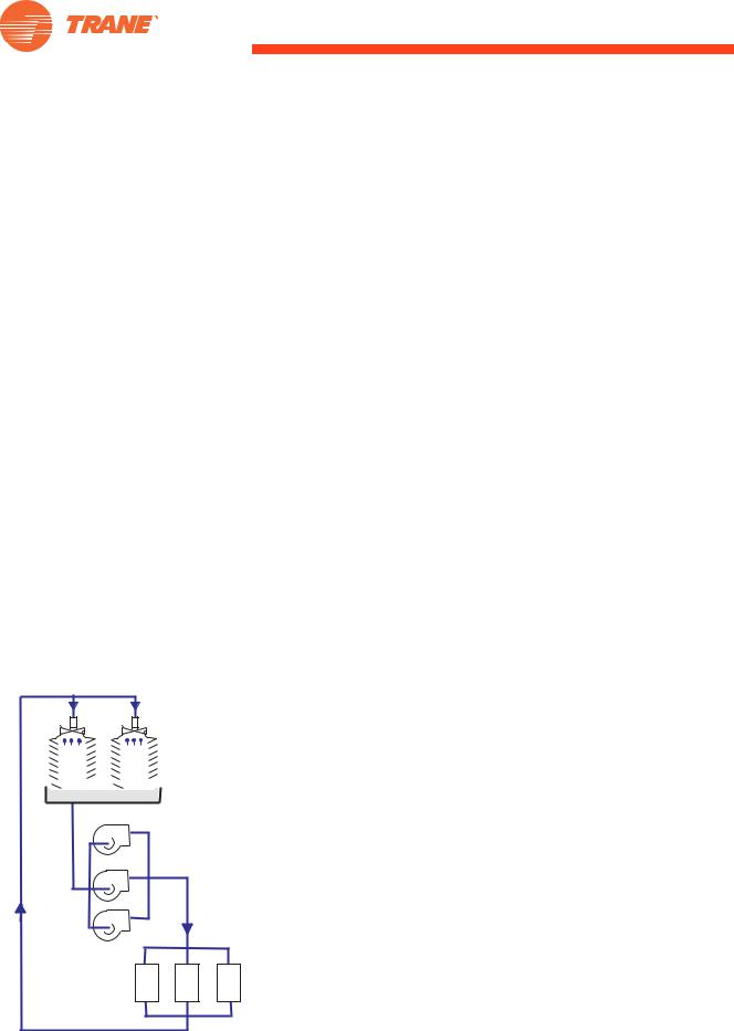
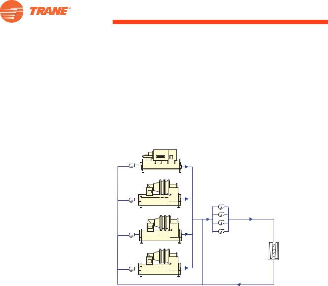
Large Chilled-Water Systems
(6+ Chillers, District Cooling)
Figure 19. Large chilled-water system schematic
~ |
~ |
~ |
~ |
~ |
Large chilled-water systems with six or more chillers (Figure 19) have different challenges than smaller systems. Examples of these types of systems are commonly found on campuses with multiple buildings, downtown districts, and mixed-use residential and commercial developments.
22 |
Chiller System Design and Control |
SYS-APM001-EN |

Application Considerations
Creating one centralized chilled-water system takes significant foresight, initial investment, and building development with a multi-year master plan. If the initial plant is built to accommodate many future buildings or loads, the early challenge is operating the system efficiently with much lower loads than it will experience when the project is complete. The system may need to blend parallel and series configurations (“Series–Counterflow Application” on page 77) to accommodate the wide range of loads the plant experiences during phased construction.
Another type of large chilled-water system could actually start out as more than one chilled water-system. An existing set of buildings can be gradually added to the central system, or two geographically distant chilled-water systems can be connected. “Plant Expansion” on page 83 discusses the unique control and hydraulic challenges of “double-ended” chilled-water systems.
Operating large chilled-water systems can be different as well. As system load drops, chillers are turned off. Individual chiller unloading characteristics are not as important, because operating chillers are more heavily loaded.
Pipe size
Practical pipe size limitations start to affect the maximum size of a chilledwater system. As the systems get larger, it becomes more difficult to accommodate the increasing pipe sizes, both in cost and in space. Large Ts can help reduce flow and required pipe size. (See “Selecting Chilledand Condenser-Water Temperatures and Flow Rates” on page 27.) In general, the larger the system, the higher the T should be.
Water
Large systems are almost always water-cooled. Both chilled water (a closed loop) and condenser water (usually an open loop) pipes will have to be filled with water. In some locations, it is difficult to find enough fresh water to fill a very large system with water, especially if the chilled-water system is quite distant from the loads. Cooling towers consume water, which can be significant and difficult to obtain in some locations. The search for both locally available make-up water and energy savings can lead to the exploration of alternative condensing sources like lake, river, or well water. (See “Well, river, or lake water” on page 72.) In rare instances, salt water or brackish water can be applied if the system uses an intermediate heat exchanger, or if the chiller is constructed with special tubes.
Power
Large chilled-water systems can be challenged by site power availability. Transformer size may be dictated by local regulations. On-site power generation may be part of the project, leading to using higher voltages inside the chilled-water system to avoid transformer losses and costs. Alternative fuels for some or all of the chillers may be attractive (“Alternative Energy Sources” on page 82).
SYS-APM001-EN |
Chiller System Design and Control |
23 |

Application Considerations
For more information about chiller plant controls, consult the Trane applications guide, Tracer Summit™ Chiller Plant Control Program (BAS-APG004-EN).
24
To minimize power, large systems must be very efficient. The upside of a large system is the amplification of energy savings. A relatively small percentage of energy saved becomes more valuable. For this reason, the highly efficient series-counterflow arrangement is popular for large systems. (See “Series–Counterflow Application” on page 77.)
Controls
The designers of medium and large chilled-water systems are more likely to consider the pros and cons of direct-digital controls (DDC) versus programmable-logic controls (PLC). These platforms deliver similar results, depending on proper design, programming, commissioning, and operation.
One way to think of PLC is “fast, centralized control with redundancy.” PLC has a faster processing speed, with some hot-redundancy features—such as an entirely redundant system processor that is ready to take over if the main system processor fails.
Conversely, DDC can be considered “steady, distributed control with reliability.” DDC controls feature easy programming and user-friendly operation. In the DDC environment, a failure of the system processor results in the lower-level processors defaulting to a pre-determined operating mode.
The speed of the PLC system can be one of its challenges. Controls that are steady and do not overreact to minor changes work very well, even in large chilled-water systems.
Chiller Plant System Performance
Chiller performance testing
All major chiller manufacturers have chiller performance test facilities in the factory, in a laboratory, or both. A chiller performance test in accordance with the test procedures in ARI Standard 550/5905 can be performed at the factory under controlled conditions, with industrial grade instrumentation and computerized data collection devices. This test ensures that the chiller meets its promised performance criteria. If it does not, corrections are made before it leaves the factory.
Limitations of field performance testing
After the chiller is installed at the job site, the system conditions will be less controllable than in a test facility, and therefore unsuitable for chiller acceptance testing. While measuring the performance of the entire chiller plant is more difficult, it can help identify operating problems or evaluate the effectiveness of system control methods and setpoints.
The goal is to operate as efficiently as possible and to sustain a high level of individual equipment and coordinated operation. A proper energy management system can help trend and diagnose problems or changes over time.
Chiller System Design and Control |
SYS-APM001-EN |
Loading...