


Installation
Operation
Maintenance
Custom
Climate Changer™
Air Handlers
Part No. X39640745010
|
|
July 2005 |
CAH-SVX01A-EN |
NOTICE:
Warnings and Cautions appear at appropriate sections throughout this manual. Read these carefully.
WARNING
...indicates a potentially hazardous situation which, if not avoided, could result in death or serious injury.
CAUTION
...indicates a potentially hazardous situation which, if not avoided, may result in minor or moderate injury. It may also be used to alert against unsafe practices.
CAUTION
...indicates a situation that may result in equipment or property-damage-only accidents.
© 2005 American Standard All rights reserved |
CAH-SVX01A-EN |

Introduction
Use this manual to install, startup, operate, and maintain the Custom Climate Changer™ air handler.
Carefully review the procedures discussed in this manual to minimize installation and startup difficulties.
Unit Description
Custom Climate Changer™ air handlers are designed for a variety of controlled-air applications. The basic unit consists of a fan, heating and/or cooling coils, filters, and dampers. See the unit submittal drawings for detailed descriptions.
Each unit is provided with a nameplate. This nameplate includes unit model number, serial number and electrical data.
The fans are internally isolated. To insure fan stability, the unit ships with a minimum of four lock-down devices that prevent the fan from shifting during shipment and installation. These spacers must be removed prior to fan operation to assure proper vibration isolation. Retain these spacers for use in adjusting fan isolators if required.
The units are available with factory mounted controls for climate and humidity control. These can be use as stand-alone devices or operate with a complete controls system. End devices include factory-mounted starters and variable speed drives.
Custom Climate Changer™ air handlers ship as complete assemblies or in sections. Some jobsite assembly is required when the units ship in sections.
Protecting the
Environment
World environmental scientists have concluded, based on the best currently available evidence, that ozone in our upper atmosphere is being reduced due to the release of CFC (chlorofluorocarbon) fully halogenated compounds.
Trane urges that all HVAC servicers working on Trane equipment, or any manufacturer’s products, make every effort to eliminate, if possible, or vigorously reduce the emission of CFC, HCFC (halocarbon that contains fluorine, chlorine, carbon, and hydrogen), and HFC (halocarbon that contains only fluorine, carbon, and hydrogen) refrigerants to the atmosphere resulting from installation, operation, routine maintenance, or major service on this equipment. Always act in a responsible manner to conserve refrigerants for continued use even when acceptable alternatives are available.
Refrigerant used in any type of airconditioning or refrigerating equipment should be recovered for reuse, recovered and/or recycled for reuse, reprocessed (reclaimed), or properly destroyed, whenever it is removed from equipment. Never release it to the atmosphere!
CAH-SVX01A-EN |
3 |

Contents |
|
Introduction ......................................................................... |
3 |
Unit Description .................................................................................. |
3 |
Protecting the Environment ................................................................ |
3 |
Contents ............................................................................... |
4 |
General Information ............................................................ |
5 |
Operating Environment ....................................................................... |
5 |
Controls ............................................................................................... |
5 |
Ultraviolet (UV) Germicidal Irradiation Lights (optional) ....................... |
6 |
Pre-Installation Requirements ........................................... |
7 |
Receiving Checklist ............................................................................. |
7 |
Resolving Shipping Damage ............................................................... |
7 |
Job Site Storage Recommendations ................................................... |
7 |
Preparing the Unit Site ........................................................................ |
8 |
Roof Curb Installation .......................................................................... |
9 |
Installation ......................................................................... |
10 |
Lifting and Rigging ............................................................................. |
10 |
Unit Assembly .................................................................................... |
11 |
TCP Model Assembly Instructions .................................................... |
12 |
TCC Model Assembly Instructions ..................................................... |
17 |
Duct Connections ............................................................................. |
24 |
Component Installation Requirements ............................................. |
24 |
Coil Piping and Connections ............................................................. |
28 |
Wiring ................................................................................................ |
41 |
External Insulating Requirements ..................................................... |
42 |
Startup ............................................................................... |
43 |
Pre-Startup Checklist ......................................................................... |
43 |
Unit Operation................................................................................... |
44 |
Determine Fan Speed ....................................................................... |
47 |
Sheave Alignment ............................................................................. |
47 |
Multibelt Check ................................................................................. |
47 |
Routine Maintenance ........................................................ |
48 |
Air Filters ........................................................................................... |
49 |
Drain Pans ......................................................................................... |
50 |
Fans ................................................................................................... |
50 |
Coils .................................................................................................. |
52 |
Moisture Purge Cycle ........................................................................ |
53 |
Internal Insulation .............................................................................. |
54 |
Ultraviolet (UV) Germicidal Irradiation Lights ..................................... |
55 |
Troubleshooting ................................................................ |
56 |
4 |
CAH-SVX01A-EN |

General
Information
Operating
Environment
When considering the placement of the Custom Climate Changer air handler, it is important to consider the operating environment. The acceptable ambient temperature range for unit operation is -40ºF to 140ºF (-40ºC to 60ºC).
For heating applications, a special motor may be required to withstand the higher temperatures. Motors with Class B insulation are acceptable for ambient temperatures up to 104º F, while motors with Class F insulation can withstand ambient temperatures to +140º F (60º C).
For the units furnished with gas furnaces, the heating demands require a special motor to withstand the higher temperatures. These motors are furnished with Class “H” insulation to withstand this rigorous duty.
Note: The customer should provide adequate freeze protection for the coils.
Controls
Wiring Sizes and
Connections
As a standard, there are no penetrations into the Custom air handler for any field-provided wiring or device. Before installation, consider overall unit serviceability and accessibility before mounting, running wires (power), making cabinet penetrations, or mounting any components to the module cabinet.
Wiring to the unit must be provided by the installer and must comply with all national and local electrical codes. The fan motor nameplate includes a wiring diagram. If there are any questions concerning the wiring of the motor, be sure to write down the information from the motor nameplate and contact your local fan motor manufacturer representative for assistance.
Factory-Mounted Controls
Small items that cannot be factory mounted will ship inside the control enclosures. Larger items may ship inside the fan module.
Note: All control valves ship directly to the “ship-to address” from the vendor unless another address is given on the Trane sales order.
Depending on job requirements, the customer may need to provide
120 Vac control power. A dedicated
15-amp circuit is recommended.
Factory-mounted control systems ordered with factory-mounted starters or VFDs are supplied with line to 24 Vac control transformers. No additional power wiring is required.
For a more in-depth understanding of controls, refer to the following manuals:
•For factory-configured AH540/ AH541 controllers, CNT-SVX05B-EN
•For programmable MP580 controllers, CNT-SVP01A-EN
•For hardware installation, CNT-SVN01A-EN
•For Danfoss VFD, TR1-SVX10A-EN
•For universal programmable control modules (UPCMs):
–EMTX-PG-5
–EMTX-IN-22A
Custom air handlers and/or fieldinstalled accessories that must be stored for a period of time prior to being installed must be protected from the elements. All controllers and electrical/ electronic components should be stored in conditions of -20 to 120°F and 5- to 95-percent relative humidity noncondensing. Electrical components are not moisture-tolerant.
Note: The warranty will not cover damage to the unit or controls due to negligence during storage. A controlled indoor environment is recommended for proper storage. For further storage considerations, refer to “Job Site Storage Recommendations” on page 7.
CAH-SVX01A-EN |
5 |

General Information
Ultraviolet (UV) Germicidal Irradiation Lights (optional)
The United States Environmental Protection Agency (EPA) believes that molds and bacteria inside buildings have the potential to cause health problems in sensitive individuals(1). If specified, Trane provides ultraviolet lights (UV-C) as a factory-engineered and installed option in select commercial air handling products.
When UV lights are factory provided, polymer materials that are susceptible to deterioration by the UV-C light will be substituted or shielded from direct exposure to the light.
In addition, UV-C radiation can damage human tissue, namely eyes and skin. To reduce the potential for inadvertent exposure to the lights by operating and maintenance personnel, electrical interlocks that automatically disconnect power to the lights are provided at all unit entry points to equipment where lights are located.
1.United Sates Environmental Protection Agency; A Brief Guide to Mold, Moisture and your Home; Brochure EPA 402-K-02-003.
6
WARNING
Equipment Damage From
Ultraviolet (UV) Lights!
Trane does not recommend field installation of ultraviolet lights in its air handling equipment for the intended purpose of improving indoor air quality. High intensity C- band ultraviolet light is known to severely damage polymer (plastic) materials and poses a personal safety risk to anyone exposed to the light without proper personal protective equipment (can cause damage to eyes and skin). Polymer materials commonly found in HVAC equipment that may be susceptible include insulation on electrical wiring, fan belts, thermal insulation, various fasteners and bushings. Degradation of these materials can result in serious damage to the equipment.
Trane accepts no responsibility for the performance or operation of our air handling equipment in which ultraviolet devices were installed outside of the Trane factory.
CAH-SVX01A-EN

Pre-Installation
Requirements
Receiving Checklist
Based on customer requirements, Custom Climate Changer air handlers can ship as complete units or as individual sections to be field assembled.
Upon receipt of the unit(s) and prior to unloading, remove any shipping material and inspect the unit for damage and verify that the shipment is complete.
Note: Delivery cannot be refused. Trane is not responsible for shipping damage.
1Visually inspect components for any damage that may have occurred during shipment.
2Check all access doors to confirm that the latches and hinges are not damaged.
3Inspect the interior of each section for any internal damage.
Note: Concealed damage must be reported within 15 days of receipt.
4Inspect the coils for damage to the fin surface and/or coil connections.
5If the unit was ordered with factory-mounted controls, locate all sensors.
Note: Items that cannot be factorymounted should ship inside the control enclosures or should be packaged inside the fan module or mixing box module.
6Check all devices attached to the unit exterior and confirm that they are not damaged.
7Manually rotate the fan wheel to ensure free movement of the shaft, bearings, and drive. Inspect the fan housing for any foreign objects.
8Locate assembly hardware.
9Inspect and test all piping for possible shipping damage. Nipples may be installed on coils at the factory but should always be tightened and tested before any connections are made. Rough handling during shipping, in addition to other factors can cause pipe connections to become loose.
Note: Trane will not be responsible for any leak at the field connections. Coils have been factory pressure tested before shipping.
Resolving Shipping
Damage
Trane air handlers ship free on board (FOB), meaning that the unit belongs to the customer the moment the delivery truck leaves the factory. If damage has occurred to the unit during shipment, follow these instructions:
Note: Trane is not responsible for shipping damage.
1Make specific notation, describing the damage, on the freight bill. Take photos of the damaged material, if possible.
2Report all claims of shipping damage to the delivering carrier immediately and coordinate carrier inspection, if necessary.
Note: Do not attempt to repair the unit without consulting the delivering carrier.
3Notify your Trane sales representative of the damage and arrange for repair.
Note: Do not attempt to repair the unit without consulting the Trane sales representative.
4Keep the damaged material in the same location as it was received.
Note: It is the receiver's responsibility to provide reasonable evidence that concealed damage was not incurred after delivery.
Job Site Storage
Recommendations
Custom units and/or field-installed accessories that must be stored for a period of time before installation must be protected from the elements. A controlled indoor environment is recommended for proper storage.
Note: The warranty does not cover damage to the unit or controls due to negligence during storage.
CAUTION
Use Canvas Only!
Use only canvas tarps to cover air handlers. Plastic tarps cause condensation to form in and on the equipment, which can result in corrosion damage or wet storage stains.
CAH-SVX01A-EN |
7 |

Pre-Installation Requirements
General Storage
The unit controller and all other electrical/electronic components should be stored in conditions of -20ºF to 120°F and 5 to 95 percent relative humidity, non-condensing. Electrical components are not moisture-tolerant. Factory protective coverings should be removed prior to storage.
Long-Term Storage
For longer periods of storage, allow proper clearance around the unit to perform periodic inspection and maintenance of the equipment.
While the unit is in storage:
•Every two weeks, rotate the fan and motor shaft 30 revolutions by hand.
•Every six months, check fan shaft bearings and grease lines. Add grease using a manual grease gun following the lubrications recommendations in “Fan Bearing Lubrication” on page 51.
Outdoor Storage
Considerations
Outdoor storage is not recommended; however, when outdoor storage is necessary, several things must be done to prevent damage:
Note: Keep the equipment in the original shipping container for protection and ease of handling.
1Select a well-drained area, preferably a concrete pad or blacktop surface.
2Place the unit on a dry surface or raised off the ground to assure adequate air circulation beneath the unit and to assure no portion of the unit will contact standing water at any time.
3Loosen the belt tension on the drive belts.
4Cover the unit securely with a canvas tarp.
5Do not stack units.
6Do not pile other material on the unit.
Preparing the Unit
Site
1Ensure the installation site can support the total weight of the unit. The building roof must be able to support the entire weight of the unit, roof curb and accessories. Refer to the unit submittals for weights.
2Allow sufficient space to allow adequate free air and necessary service access. Refer to submittals for specific minimums.
3Allow room for supply and return piping, ductwork, electrical connections, and coil removal.
4Ensure there is adequate height for condensate drain requirements. See “Drain Pan Trapping” on page 29.
Note: Inadequate height may necessitate core-drilling the floor to attain proper trap height. Insufficient height could inhibit condensate drainage and result in flooding the unit and/or equipment room.
WARNING
Level Foundation!
The floor or foundation must be level and the condensate drain at the proper height for proper coil drainage and condensate flow. Standing water and wet surfaces inside air-handling units could result in microbial growth, which may cause unpleasant odors, serious health problems, or death.
5Confirm the foundation of the mounting platform is level and large enough to include the unit dimensions (refer to the unit submittals for specific dimensions).
6Provide adequate lighting for maintenance personnel to perform maintenance duties.
7Provide permanent power outlets in close proximity to the unit for installation and maintenance.
8Depending upon job requirements, the customer may need to provide 120 Vac power to the unit controller. Refer to submittals for more information. A dedicated 15-amp circuit is recommended.
9Wiring for Custom units must be provided by the installer and must comply with all national and local electrical codes.
10Rooftop curb mounted units must be sealed tightly to the curb. Use proper sealants and roof to curb sealing techniques to prevent water and air leakage.
Note: Preparation of the roof curb or pier mount and roof openings should be completed prior to lifting the unit to the roof.
8 |
CAH-SVX01A-EN |
Pre-Installation Requirements
Roof Curb
Installation
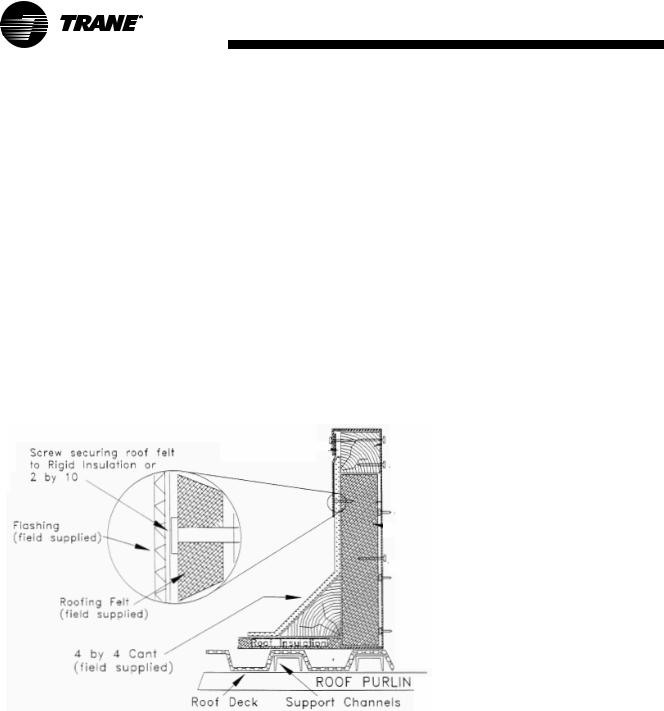
It is recommended that the curb be installed directly on the support members and fastened to the supports using tack welds or other equivalent methods. Properly supported decking should be installed inside the air handler section of the curb when this method is used. (See Figure 1)
Figure 1. Cross section of typical curb installation on new construction
CAH-SVX01A-EN
Typical Curb Installation
Checklist
•Verify that the roof structure can adequately support the combined weight of the unit and curb assembly.
•Ensure that the selected installation location provides sufficient service and operational clearances.
•Remove any twist within the curb due to roof supports and square the curb.
•Level the curb.
•Secure the curb to the roof support members.
•Install 2-inch thick boards or rigid insulation around the curb.
•Install cant strips around the curb.
•Bring field supplied roofing felt up to the top of the curb nailing strips. ail felt into place.
•Install field supplied flashing under the lip of the curb flanges and over the felt.
•Apply sealant to the four corners. Caulk all joints between the curb and the roof. Attach the gasket material to the curb’s top flanges (entire perimeter) and to the supply and return air duct opening panel flanges.
9
Installation
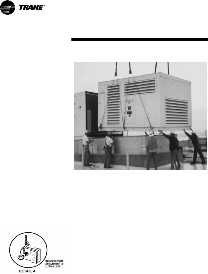
Lifting and Rigging
WARNING
Lifting and Rigging!
Do not lift, rig, or ceiling-suspend from the top of the unit. Lift from lifting lugs only, located at the bottom of the unit. Use all lifting lugs provided.
Do not use cables (chains or slings) except as shown. Each of the cables (chains or slings) used to lift the unit must be capable of supporting the entire weight of the unit. Lifting cables (chains or slings) may not be of the same length. Adjust as necessary for even unit lift.
Do not use a fork lift for handling units. This may result in equipment damage. Trane is not responsible for equipment damage resulting from improper forklifting practices.
Test lift unit approximately 24 inches to verify proper center of gravity lift point. To avoid dropping of unit, reposition lifting point if unit is not level.
Always place, assemble, and suspend sections one at a time.
Failure to follow instructions could result in death or serious injury or equipment damage.
Figure 2. Recommended attachment to lifting lugs.
Figure 3. Use proper lifting and rigging methods
Per job requirements, air handlers will ship as a complete assembly or in sections.
Trane recommends that the contractor use spreader bars and slings to rig units and subassemblies.
Before preparing the unit for lifting, estimate the approximate center of gravity for lifting safety. Because of the placement of internal components, the unit weight may be unevenly distributed, with more weight in the coil and fan areas. Refer to the unit submittals for section weights. Test the unit for proper balance and rigging before lifting.
General Lifting
Considerations
•Always rig subassemblies or sections as they ship from the factory. See the unit submittal drawings for correct placement of sections.
•Always assemble unit at the installation site. Never bolt sections together before rigging.
•Make the loop of the sling parallel to the direction of airflow, if possible.
•Each of the cables used to lift the unit must be capable of supporting the entire weight of the unit.
•When hoisting the unit into position, use the proper rigging method, such as straps, slings, spreader bars, or lifting lugs for protection and safety.
Note: Never lift units in windy conditions.
10 |
CAH-SVX01A-EN |
Installation
•Personnel should be positioned overhead and on the ground to guide the crane or helicopter operator in positioning the sections.
•The air handler is not designed to be lifted, rigged or ceiling suspended from the top of the unit.
•Never stack the pipe cabinet and inlet hoods on the unit as the unit is being lifted.
•Do not attach the intake/exhaust hoods to the unit prior to lifting the unit. Doing so may damage the equipment. Attach the hoods to the unit only after all sections are in place.
Unit Assembly
Note: If the unit is shipped as a complete assembly, go to “Coil Piping and Connections” on page 28.
Prior to unit assembly, refer to the unit submittal drawings and unit tagging for correct placement of sections. Failure to review the submittal drawings could result in performance or assembly problems. If there are any discrepancies, contact your local Trane sales representative before proceeding.
All shipping supports and crating on the face of the sections must be removed and discarded to permit proper fit-up and sealing of the surfaces.
Units may be mounted on the roof with a roof curb or pier mount. Units may be mounted indoors on housekeeping pads. Refer to submittals for unit dimensions and openings.
Note: For proper operation, the unit must be supported around the entire unit base perimeter. If the unit is shipped in sections, the entire section perimeter must be supported, as well as at the base channels of the unit splits.
Provide clearance around the unit to allow adequate free air and necessary service access. Also, allow room for supply and return piping, ductwork, electrical connections, and coil removal.
The building roof must be able to support the entire weight of the unit, roof curb and accessories. See submittals for approximate unit weights.
•Preparation of the roof curb or pier mount and roof openings should be completed prior to lifting the unit to the roof.
•Check that the gasketing or sealant on the roof curb is intact and provides an airtight seal with the unit base.
•Complete all ductwork, piping and electrical connections only after mounting the unit.
Assembly Hardware
Air handlers ship with all necessary assembly hardware and gasket material. This hardware is packaged in either a clear plastic envelope or cardboard box and can be found inside one of the sections. If space inside a section is not adequate, a crate or pallet will be loaded onto the bed of the truck. Check the Parts List on the Field Assembly drawing against the contents of the crate. Do not proceed with unit assembly until verification that all materials are present. The number of sections to be assembled often makes it necessary to use more than one section to ship the material. Please check all sections thoroughly before contacting your local Trane sales engineer to report missing hardware.
CAH-SVX01A-EN |
11 |
Installation
TCP Model
Assembly
Instructions
If your nameplate model number begins with TCP, use the assembly instructions below.
Joining Sections Edge-to-
Edge
Units must be installed level for proper drainage of condensate from the drain pan. In addition, each section in a multi-section unit must be properly supported.
Note: Leveling each section, beginning with the first, is critical. Failure to level and align the sections immediately creates greater misalignment or even structural damage afterward.
1Remove all crating and wrapping from the surfaces to be joined.
2Place one section of the air handler into the desired position. Verify each section is level and properly supported prior to proceeding with assembly. Each unit must be level side-to-side and front to back. Check squareness measuring the critical dimensions given.
3When the unit is positioned and squareness is assured within 1/8- inch, remove all lifting lugs located along the split plane.
4Install 4-inch x 1/4-inch neoprene gasket to all mating surfaces of the section, including the internal walls. This gasket must be applied to the full perimeter of the section split of both sections to be joined.
5Move the next mating section into alignment with the positioned section. Alignment of sections must be completed before gasket surfaces meet. The
two sections should be within 12 inches to reduce the amount of dragging required.
6Remove lifting lugs on mating section as required.
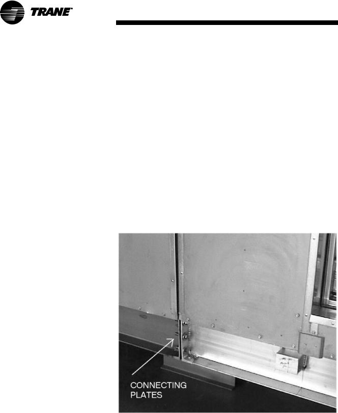
7Insert threaded rods through each hole of each mating connecting plate (see Figure 4). Bring each connecting surface together uniformly until gasketing is contacted.
Note: Use field provided threaded rods inserted in all holes of each connecting plate to prevent damage and distortion of the sections as they are joined. Tighten all rods in sequence. Do not try to join sections by tightening only some of the rods.
Note: Failure to compress the gasketing may result in air leakage.
8Secure the unit sections at the base using the field provided bolts, nuts and washers at the connecting plates.
9Once the sections are pulled together, install the assembly hardware as applicable for the walls, roof, and the base as demonstrated in the following assembly sections.
Figure 4. Insert threaded rods through each hole of mating connecting plate.
12 |
CAH-SVX01A-EN |
TCP Base Section
Assembly (Typical)
Note: Failure to completely compress the gasketing may result in air leakage.
1Join the two units and secure with field provided 5/8-inch flat washers and 5/8-inch X 2-1/2-inch grade 9 bolts though each of the six holes.
2Caulk the overlapping flange along the length of each split to maintain a seal.
Note: Use a polyurethane or equivalent caulk.
Installation
3Apply the 3-inch X 1/8-inch gasket evenly across the two joined edges of the splits.
4Before installing the pre-cut 4- inch 18 gauge joining strip over the gasket, pre-drill holes in the floor using the 4-inch strip as a guide with a 7/32-inch drill bit at 12 inch centers.
5Apply the 4-inch joining strip over the gasket and uniformly straddle the splits. Secure with number 14 sheet-metal screws at 12-inch centers.
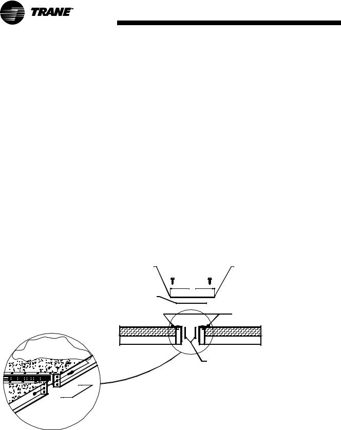
Figure 5. TCP base assembly
PREDRILL HOLES |
18 GAUGE JOINING STRIP |
|
WITH 7/32" |
DRILL BIT. |
SECURE W/#14 S.M. SCREWS |
|
|
@ 12" CTR'S. |
|
3" X 1/8" GASKET |
4" |
|
|
|
|
|
ADD CAULKING BEFORE |
|
|
ADDING JOINING STRIPS. |
JOIN WITH
5/8" FLAT WASHER 5/8" X 2 1/2" GRADE 9 BOLTS
A |
SPLIT |
SPLIT |
4" X 1/4" GASKET.
A
BASE ASSEMBLY.
CAH-SVX01A-EN |
13 |
Installation
TCP Wall Section Assembly (Typical)
1Apply the walls and join at the inside angles with number 14 sheet-metal screws on 12-inch centers along the length of the angles.
2Apply the 1/8-inch gasket evenly to the exterior of the walls across the two joined edges of the splits.
3Before installing the pre-cut joining strip over the gasket, predrill holes in the wall using the strip as a guide with a number 29 drill bit at 12-inch centers.
4Apply the joining strip over the gasket and uniformly straddling the splits. Secure with number 10 sheet metal screws.
5Fit the pre-cut hub cap over the joining strip the vertical height of the wall flush with the roof and secure it to the wall with number 8 sheet metal screws. Fill the top and bottom openings with caulk as moisture seal. Pre drill holes with a number 29 bit.
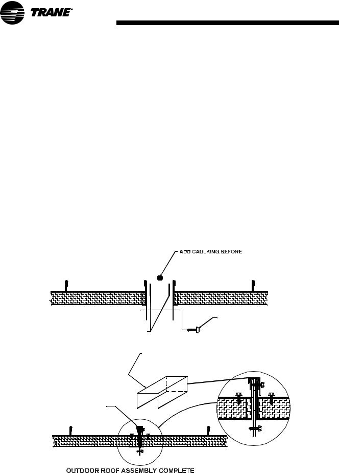
TCP Outdoor Roof Section
Assembly (Typical)
1Align the roof splits and join the interior section trim with number 14 sheet metal screws on 12 inch centers.
2Add a bead of caulk along the length of the roof seams. Install the pre-cut J-cap over the seam and secure with number 14 sheet metal screws on 12-inch centers.
Note: Use a polyurethane or equivalent caulk. It may be necessary to clamp the joint together or predrill to prevent separation when drilling with screws.
3Apply caulk to the end cap interior surface. Secure the end cap on the J-cap with one number 10 screw.
Figure 6. TCP outdoor roof assembly |
|
|
INSTALLING J-CAP |
SPLIT |
SPLIT |
SECTION TRIM ACTS AS
AS JOINING ANGLE
4" X 1/4" GASKET |
SECURE w/#14 S.M. |
@ 12" CENTERS.
APPLY CAULKING TO END CAPS
THEN SECURE END CAPS
TO THE ENDS OF J CAP.
|
J-CAP |
SECURE J-CAP |
END CAP |
W/#14 S.M. SCREWS. |
14 |
CAH-SVX01A-EN |
Installation
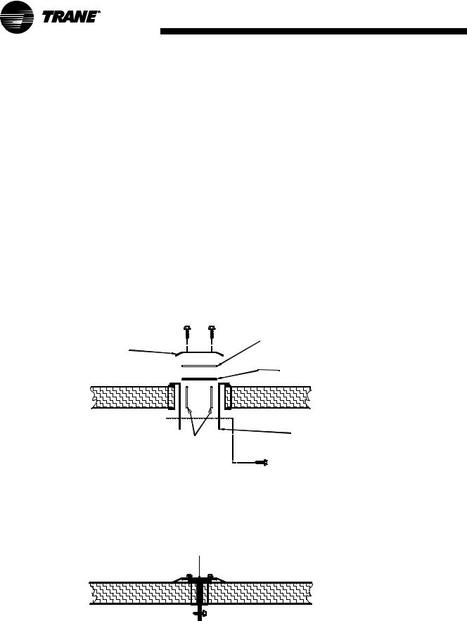
TCP Indoor Roof Section
Assembly (Typical)
1Align the walls and join the inside angles with number 14 sheet metal screws on 12-inch centers along the length of the angles.
2Apply a bead of caulk along the length of the roof seam joint.
3Apply the 1/8-inch gasket on the exterior of the roof evenly across the roof split.
4Before installing the pre-cut joining strip over the gasket, predrill holes in the roof using the strip as a guide with a number 29 drill bit at 12-inch centers.
5Apply the joining strip over the gasket and uniformly straddling the splits. Secure with #10 sheet metal screws.
6Fit the pre-cut hub cap and secure it to the roof with #8 sheet metal screws. Fill the end openings with caulk as moisture seal. Note: Pre drill the screw holes with a number 29 bit.
Figure 7. TCP indoor roof assembly
PREDRILL HOLES
WITH #29 DRILL BIT.
SECURE HUB CAP W/#8
S.M. SCREWS.
4" X 1/4" GASKET 
3" JOINING STRIP
SECURE WITH #10 S.M. SCREWS.
3" X 1/8" THICK GASKET |
(2) 1 1/4" X 6" GALVANIZED ANGLE |
SECURED W/ #14 S.M. SCREWS |
@ 12" CENTERS |
INDOOR ROOF ASSEMBLY COMPLETE
SPLIT
CAH-SVX01A-EN |
15 |
Installation
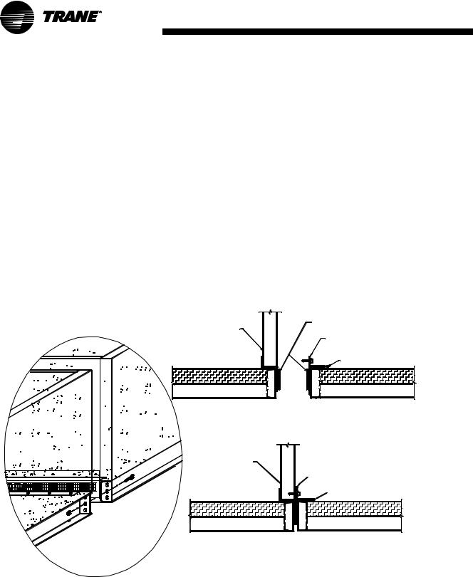
TCP Base to Interior Wall Section Assembly (Typical)
Note: Failure to completely compress the gasketing may result in air leakage.
1Join the two units and secure with field provided 5/8-inch flat washers and 5/8-inch X 2-1/2-inch grade 9 bolts though each of the six holes.
2Apply caulk the length of the base between the 2-inch X 2-inch angle on the one base section and the wall on the adjoining section. See Illustration below. Note: Use a polyurethane or equivalent caulk.
3Secure the 2-inch X 2-inch angle to the adjoining wall with number 14 sheet-metal crews on 12-inch centers along the length of the angle and wall.
Figure 8. TCP base to interior wall sections
INTERIOR |
WALL |
SPLIT |
4" X 1/4" GASKET
SECURE 2" X 2" ANGLE TO WALL W/#14 S.M. SCREWS @ 12" CTR'S
CAULK |
SPLIT |
INTERIOR |
|
WALL |
CAULK |
|
|
|
CAULK |
SPLIT |
SPLIT |
BASE TO WALL ASSEMBLY COMPLETE
16 |
CAH-SVX01A-EN |
TCC Model
Assembly
Instructions
If your nameplate model number begins with TCC, use the assembly instructions below.
Joining sections - Edge to Edge
Units must be installed level for proper drainage of condensate from the drain pan and for squareness of the sections during installation. In addition, each section in a multisection unit must be properly supported.
Note: Leveling each section, beginning with the first section, is critical. Failure to level and align the sections immediately creates greater misalignment or even structural damage afterward.
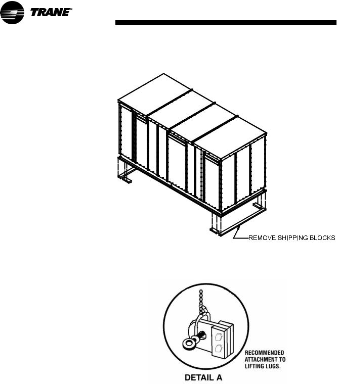
•Remove all wooden blocks under the unit and shipping protection from adjoining surfaces (see Figure 9).
•Place the first section of the air handler on the end of the roof curb or the housekeeping pad. The section must be level from side-to-side and front to back.
Section squareness should be within 1/8-inch. Remove the bottom bolts from lifting lugs located at the shipping split (see Figure 10).
CAH-SVX01A-EN
Installation
Figure 9. Remove shipping blocks
Figure 10. Remove lifting lug bolts
17

Installation
• Apply 1.25-inch x 0.33-inch |
• Move the next unit section as |
ribbed butyl tape to the shipping |
close as possible from the |
split channel and shipping split |
previous section. The two |
plates (see Figure 11). |
sections should be close enough |
• Verify the section is level prior to |
to reduce the amount of |
|
proceeding with the next section |
dragging required. This is |
|||
particularly important when |
||||
of the unit. |
||||
mounting on a roof curb to |
||||
|
|
|
||
|
|
|
minimize damage to the sealant |
|
|
|
|
on the roof curb. Alignment of |
|
|
|
|
sections must be completed |
|
|
|
|
before drawing sections |
|
|
|
|
together. |
|
|
|
|
• Remove the bottom bolts from |
|
|
|
|
the shipping split lifting lugs (see |
|
|
|
|
Figure 12). |
|
Figure 11. Apply butyl tape to shipping splits |
||||
|
|
|
|
|
18
Figure 12. Remove bottom bolts from lifting lugs
CAH-SVX01A-EN
 Loading...