


RT-DS-10
RT-DS-10
April 1999
Packaged
Rooftop
Air Conditioners
23 to 42 Ton (81-148 kW)
Voyager
Commercial 50 HZ
2
©American Standard Inc. 1999
Features
and
Benefits
Over the years the Voyager
product
line has developed into the most
complete line of commercial packaged
units available. We were first with the
Micro when we developed micro-
electronic unit controls and we move
ahead again with Voyager Commercial
products.
Five new sizes from 23-42 tons (81-148
kW) meet the needs of the changing
commercial rooftop marketplace.
Our customers demand units that will
have exceptional reliability, meet
stringent performance requirements,
and be competitively priced. These
same requirements drove the design of
the original light commercial Voyager
and have been carried forward into
Voyager Commercial.
Voyager Commercials features and
benefits are comprised of cutting edge
technologies like the reliable 3-D
Scroll compressor, Trane engineered
microprocessor controls, computer-
aided run testing, and Integrated
Comfort
systems. So, whether youre
the contractor, the engineer, or the
owner you can be certain that when
youve chosen Voyager Commercial,
youve chosenSimply the best value!
3
ContentsContents
Optional Features
Electric heat
Natural gas heat
LP gas heat (kit only)
Power exhaust
Barometric relief
High efficiency 2 (51 mm) throwaway
filters
High efficiency 4 (102 mm) throwaway
filters
High efficiency supply fan motors
Manual fresh air damper
Economizer with dry bulb control
Economizer with reference enthalpy
control
Economizer with differential
(comparative) enthalpy control
Inlet guide vanes on VAV units
Service valves
Through-the-base electrical provision
Factory mounted disconnect with
external handle (non-fused)
Integrated Comfort
system control
option
Ventilation override
Hinged service access
Factory installed condenser
coil guards
Standard Features
Factory installed and commissioned
microelectronic controls
Trane 3-D
Scroll compressors
Dedicated downflow or horizontal
configuration
CV or VAV control
FROSTAT
coil frost protection on all
units
Supply air overpressurization
protection on VAV units
Supply airflow proving
Emergency stop input
Compressor lead-lag
Occupied-unoccupied switching
Timed override activation
FC supply fans
Two-inch (51 mm) standard efficiency
filters
Finish exceeds salt spray requirements
of ASTM B117
Features and Benefits 2
Model Number Description 9
General Data 10
Application Considerations 13
Selection Procedure 15
Performance Adjustment Factors
17
Performance Data 18
Electrical Data 30
Controls 32
Dimensional Data 35
Weights 38
Field Installed Sensors 39
Mechanical Specifications 42
4
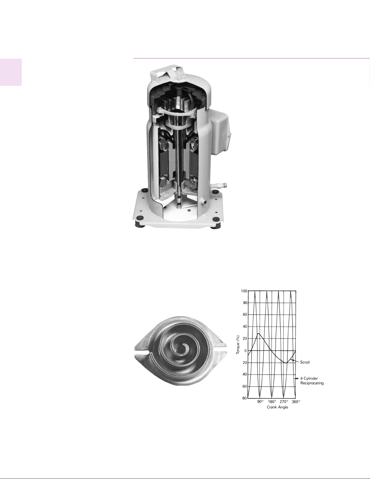
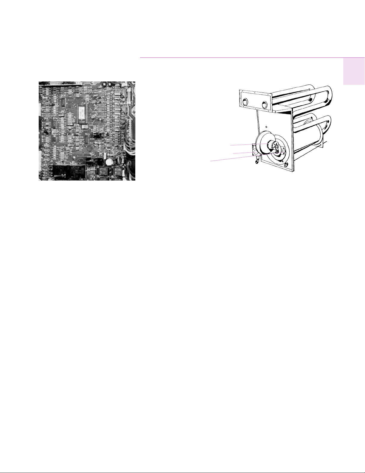
One of two matched scroll plates the
distinguishing feature of the scroll
compressor.
Chart illustrates low torque variation of
3-D Scroll compressors reciprocating
compressor.
Trane 3-D
®
Scroll Compressor
Simple Design with 70% Fewer Parts
Fewer parts than an equal capacity
reciprocating compressor means
significant reliability and efficiency
benefits. The single orbiting scroll
eliminates the need for pistons,
connecting rods, wrist pins and valves.
Fewer parts lead to increased reliability.
Fewer moving parts, less rotating mass
and less internal friction means greater
efficiency than reciprocating
compressors.
Patented 3-D Scroll Compliance
Trane 3-D Scroll compliance provides
important reliability and efficiency
benefits. 3-D compliance allows the
orbiting scrolls to touch in all three
dimensions, forming a completely
enclosed compression chamber which
leads to increased efficiency. In
addition, 3-D compliance means the
orbiting scrolls only touch with enough
force to create a seal so there is no
wear between the scroll plates. The
fixed and orbiting scrolls are made of
high strength cast iron which results in
less thermal distortion, less leakage,
and higher efficiencies. The most
outstanding feature of the scroll
compressor 3-D compliance is that the
slugging will not cause failure. In a
reciprocating compressor, however, the
liquid or dirt can cause serious
damage.
Low Torque Variation
The 3-D Scroll compressor has a very
smooth compression cycle with torque
variations that are only 30 percent of
that produced by a reciprocating
compressor. This means the scroll
compressor imposes very little stress
on the motor for greater reliability. Low
torque variation means reduced noise
and vibration.
Suction Gas Cooled Motor
Compressor motor efficiency and
reliability is further optimized with this
design. Cool suction gas keeps the
motor cooler for longer life and better
efficiency.
Proven Design Through Testing and
Research
With over twenty years of development
and testing, Trane 3-D Scroll
compressors have undergone more
than 400,000 hours of laboratory
testing and field operation. This work
combined with over 25 patents makes
Trane the worldwide leader in air
conditioning scroll compressor
technology.
Features
and
Benefits
5
Features
and
Benefits
Micro Controls
For over 10 years Trane has been
working with microprocessor controls
in the applied equipment markets.
These designs have provided the
technology that has been applied to the
Voyager units.
The Micro provides unit control for
heating, cooling and ventilating
utilizing input from sensors that
measure outdoor and indoor
temperature.
The Micro improves quality and
reliability through the use of time-
tested microprocessor controls and
logic. The Micro:
prevents the unit from short cycling,
considerably improving compressor
life.
ensures that the compressor will run
for a specific amount of time which
allows oil to return for better
lubrication, enhancing the reliability of
the commercial compressor.
The Voyager with the Micro reduces
the number of components required to
operate the unit, thereby reducing
possibilities for component failure.
Quality and Reliability
Drum and Tube Heat Exchanger
The drum and tube heat exchanger is
designed for increased efficiency and
reliability and has utilized improved
technology incorporated in the large
roof top commercial units for almost
20 years.
The heat exchanger is manufactured
using aluminized steel with stainless
steel components for maximum
durability. The requirement for cycle
testing of heat exchangers is 10,000
cycles by ANSI Z21.47. This is the
standard required by both UL* and
AGA* for cycle test requirements.
Trane requires the design to be tested
to 2
1
/2 times this current standard. The
drum and tube design has been tested
and passed over 150,000 cycles which
is over 15 times the current ANSI
cycling requirements.
*Apply to 60 HZ testing standards only.
The negative pressure gas valve will
not allow gas flow unless the
combustion blower is operating. This is
one of our unique safety features.
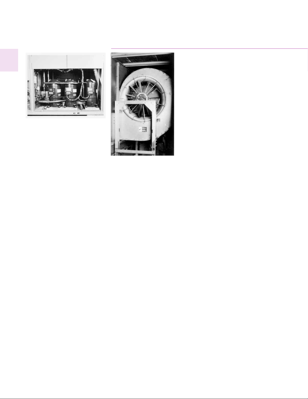
The forced combustion blower supplies
premixed fuel through a single
stainless steel burner screen into a
sealed drum where ignition takes place.
It is more reliable to operate and
maintain than a multiple burner
system.
The hot surface ignitor is a gas ignition
device which doubles as a safety
device utilizing a continuous test to
prove the flame. The design is cycle
tested at the factory for quality and
reliability.
Forced Combustion Blower
Negative Pressure Gas Valve
Hot Surface Ignitor
Drum and Tube Heat Exchanger
6
Features
and
Benefits
Excellent Part-Load Efficiency
The Scroll compressors unique design
allows it to be applied in a passive
parallel manifolded piping scheme,
something that a recip just doesnt
do very well.
When the unit begins stage back at part
load it still has the full area and circuitry
of its evaporator and condenser coils
available to transfer heat. In simple
terms this means superior part-load
efficiencies (IPLV) and lower unit
operating costs.
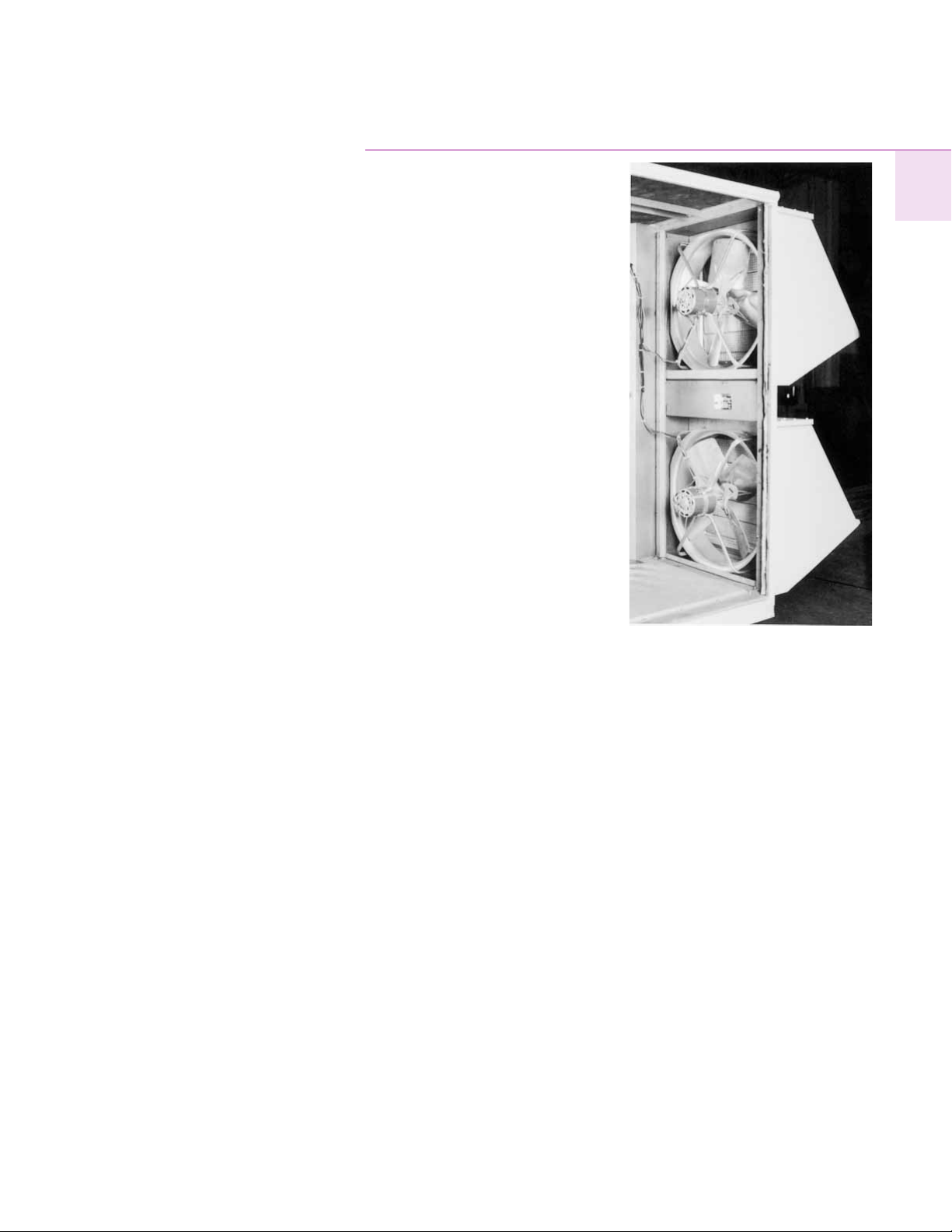
FC Fans with Inlet Guide Vanes
Tranes forward-curved fans with inlet
guide vanes pre-rotate the air in the
direction of the fan wheel, decreasing
static pressure and horsepower,
essentially unloading the fan wheel.
The unloading characteristics of a
Trane FC fan with inlet guide vanes
result in superior part load
performance.
Rigorous Testing
All of Voyagers designs were
rigorously rain tested at the factory to
ensure water integrity.
Actual shipping tests are performed to
determine packaging requirements.
Units are test shipped around the
country. Factory shake and drop tested
as part of the package design process
to help assure that the unit will arrive at
your job site in top condition.
Rigging tests include lifting a unit into
the air and letting it drop one foot,
assuring that the lifting lugs and rails
hold up under stress.
We perform a 100% coil leak test at the
factory. The evaporator and condenser
coils are leak tested at 200 psig and
pressure tested to 450 psig.
All parts are inspected at the point of
final assembly. Sub-standard parts are
identified and rejected immediately.
Every unit receives a 100% unit run test
before leaving the production line to
make sure it lives up to rigorous Trane
requirements.
Ease of Installation
Contractors look for lower installation
(jobsite) costs. Voyagers
conversionless units provide many
time and money saving features.
Conversionless Units
The dedicated design units (either
downflow or horizontal) require no
panel removal or alteration time to
convert in the field a major cost
savings during installation.
Improved Airflow
U-shaped airflow allows for improved
static capabilities. The need for high
static motor conversion is minimized
and time isnt spent changing to high
static oversized motors.
Single Point Power
A single electrical connection powers
the unit.
Micro
The function of the Micro replaces the
need for field installed anti-short-cycle
timer and time delay relays. The Micro
ensures that these controls are integral
to the unit. The contractor no longer
has to purchase these controls as
options and pay to install them.
The wiring of the low voltage
connections to the unit and the zone
sensors is as easy as 1-1, 2-2, and 3-3.
This simplified system makes it easier
for the installer to wire.
7
Features
and
Benefits
Serviceability
Todays owners are more conscious of
the cost of service and maintenance.
Voyager was designed with input from
service contractors. Their information
helped us design a unit that would get
the serviceman off the job quicker and
save the owner money. Here is why
Voyager can save money in service.
Voyagers Simpler Design
The Voyager design uses fewer parts
than previous units. Since it is simpler
in design, it is easier to diagnose.
Micro
The Micro requires no special tools to
run the Voyager unit through its paces.
Simply place a jumper between Test 1
and Test 2 terminals on the Low
Voltage Terminal Board and the unit
will walk through its operational steps
automatically.
The unit automatically returns control
to the zone sensor after stepping
through the test mode a single time,
even if the jumper is left on the unit.
As long as the unit has power and the
system on LED is lit, the Micro is
operational. The light indicates that the
Micro is functioning properly.
The Micro features expanded
diagnostic capabilities when utilized
with Tranes Integrated Comfort
Systems.
Some zone sensor options have central
control panel lights which indicate the
mode the unit is in and possible
diagnostic information (dirty filters for
example).
Easy Access Low Voltage
Terminal Board
Voyagers Low Voltage Terminal Board
is external to the electrical control
cabinet. It is extremely easy to locate
and attach the thermostat wire. This is
another cost and timesaving
installation feature.
Value
Low Ambient Cooling
All Voyager Commercial units have
cooling capabilities down to 0°F
(-17.8°C) as standard.
Power Exhaust Option
Provides exhaust of the return air when
using an economizer to maintain
proper building pressurization. Great
for relieving most building
overpressurization problems.
Micro Benefits
The Micro in the Voyager units has
built-in anti-short-cycle timer, time
delay relay and minimum on time
controls. These controls are functions
of the Micro and are factory tested to
assure proper operation.
The Micro softens electrical spikes by
staging on fans, compressors and
heaters.
The Intelligent Fallback or Adaptive
Control is a benefit to the building
occupant. If a component goes astray,
the unit will continue to operate at
predetermined temperature setpoint.
Intelligent Anticipation is a standard
feature of the Micro. It functions
constantly as the Micro and zone
sensor work together in harmony to
provide tighter comfort control than
conventional electromechanical
thermostats.

8
VariTrac
Tranes changeover VAV System for
light commercial applications is also
available. Coupled with Voyager
Commercial, it provides the latest in
technological advances for comfort
management systems and can allow
thermostat control in every zone served
by VariTrac
.
Downflow and Horizontal Economizers
The economizers come with three
options of controls (dry bulb, enthalpy
and differential enthalpy).
Trane Communication Interface or TCI
is available factory or field installed.
This module when applied with the
Micro easily interfaces with Tranes
Integrated Comfort
system.
Trane factory built roof curbs are
available for all units.
One of Our Finest Assets:
Trane Commercial Sales Engineers are
a Support group that can assist you
with:
Product
Application
Service
Training
Special Applications
Specifications
Computer Programs and more
Features
and
Benefits
VariTrac
CCP
9
Model
Number
Description
TC D 400 A C 0 A 1 A 4 F D 1 A
1,2 3 4,5,6 7 8 9 10 11 12 13 14 15 16 17
Note:
1. All voltages are across-the-line starting only.
2. Option includes Liquid, Discharge, Suction Valves.
3. Supply air fan drives A thru G are used with 22.9-29.2 ton (82-105 kW) units only and
drives H thru N are used with 33.3 and 41.7 ton (120-148 kW) units only.
4. Electric Heat kW ratings are based upon voltage ratings of 380/415 V. Heaters A, B, C, D
are used with 22.9-29.2 ton (82-105 kW) units only and heaters B, C, D, E are used with
33.3-41.7 ton (120-148 kW) units only.
Digits 1, 2 Unit Function
TC = DX Cooling, No Heat
TE = DX Cooling, Electric Heat
YC = DX Cooling, Natural Gas Heat
Digit 3 Unit Airflow Design
D = Downflow Configuration
H = Horizontal Configuration
Digits 4, 5, 6 Nominal Cooling Capacity
275 = 22.9 Tons (82 kW)
305 = 25.4 Tons (89 kW)
350 = 29.2 Tons (105 kW)
400 = 33.3 Tons (120 kW)
500 = 41.7 Tons (148 kW)
Digit 7 Major Development Sequence
A = First
B = Second, Etc.
Digit 8 Power Supply (See Note 1)
C = 380/50/3
D = 415/50/3
Digit 9 Heating Capacity (See Note 4)
0 = No Heat (TC only)
L = Low Heat (YC only)
H = High Heat (YC only)
Note: When second digit is E for Electric
Heat, the following values apply in the
ninth digit.
380V / 415V
A = 23 27 kW
B = 34 40 kW
C = 45 54 kW
D = 56 67 kW
E = 68 81 kW
Digit 10 Design Sequence
A = First
Digit 11 Exhaust
0 = None
1 = Barometric Relief
(Available w/Economizer only)
2 = Power Exhaust Fan
(Available w/Economizer only)
Digit 12 Filter
A = Standard 2 (51 mm) Throwaway Filters
B = High Efficiency 2 (51 mm) Throwaway
Filters
C = High Efficiency 4 (102 mm) Throwaway
Filters
Digit 13 Supply Fan Motor, HP
1 = 7.5 Hp Std. Eff. (5.6 kW)
2 = 10 Hp Std. Eff. (7.5 kW)
3 = 15 Hp Std. Eff. (11.2 kW)
4 = 20 Hp Std. Eff. (14.9 kW)
Digit 14 Supply Air Fan Drive Selections
(See Note 3)
A = 458 H = 417
B = 500 J = 437
C = 541 K = 479
D = 583 L = 521
E = 625 M = 562
F = 658 N = 604
G = 664
Digit 15 Fresh Air Selection
A = No Fresh Air
B = 0-25% Manual Damper
C = 0-100% Economizer, Dry Bulb Control
D = 0-100% Economizer, Reference
Enthalpy Control
E = 0-100% Economizer, Differential
Enthalpy Control
F = C Option and Low Leak Fresh
Air Damper
G = D Option and Low Leak Fresh
Air Damper
H = E Option and Low Leak Fresh
Air Damper
Digit 16 System Control
1 = Constant Volume
2 = VAV Supply Air Temperature Control
w/o Inlet Guide Vanes
3 = VAV Supply Air Temperature Control
w/Inlet Guide Vanes
Note: Zone sensors are not included with
option and must be ordered as a separate
accessory.
Digit 17+ Miscellaneous
A = Service Valves (See Note 2)
B = Through the Base Electrical Provision
C = Non-Fused Disconnect Switch with
External Handle
D = Factory-Powered 15A GFI
Convenience Outlet and Non-Fused
Disconnect Switch with
External Handle
E = Field-Powered 15A GFI
Convenience Outlet
F = ICS Control Option Trane
Communication Interface, Supply Air
Sensing and Clogged Filter Switch
G = Ventilation Override
H = Hinged Service Access
J = Condenser Coil Guards
10
Table 10-1 General Data 23-25 Tons
TC*275 (23 Tons) TC*305 (25 Tons)
Cooling Performance
1
Nominal Gross Capacity(Btuh) 279,000 (81.8 kW) 304,000 (89.1 kW)
System Power kW 26.1 30.2 kW
Compressor
Number/Type 2/Scroll 2/Scroll
Nominal Motor HP (ea) 8.4/12.5 11.7
Motor RPM 2875 2875
Natural Gas Heat
2
Low High Low High
Heating Input(Btuh) 290,000 (85.0 kW) 500,000 (147 kW) 290,000 (85.0 kW) 500,000 (147 kW)
First Stage 250,000 (73.3 kW) 425,000 (125 kW) 250,000 (73.3 kW) 425,000 (125 kW)
Heating Output(Btuh) 243,000 (69.0 kW) 405,000 (119 kW) 243,000 (69.0 kW) 405,000 (119 kW)
First Stage 202,500 (59.4 kW) 344,250 (101 kW) 202,500 (59.4 kW) 344,250 (101 kW)
Steady State Efficiency(%)
3
81 81
No. Burners/No. Stages 1/2 1/2
Gas Connect Pipe Size (in) 0.75 (19 mm) 0.75 (19 mm)
Outdoor Coil - Type LANCED LANCED
Tube Size OD (in) 0.375 (10 mm) 0.375 (10 mm)
Face Area (sq ft) 51.3 (4.8 sq m) 51.3 (4.8 sq m)
Rows/Fins Per Inch (25mm) 2/16 2/16
Indoor Coil - Type HI-PERFORM HI-PERFORM
Tube Size OD (in) 0.500 (13 mm) 0.500(13 mm)
Face Area (sq ft) 31.7 (2.9 sq m) 31.7 (2.9 sq m)
Rows/Fins Per Inch (25mm) 2/14 2/14
Refrigerant Control TXV TXV
PVC Drain Connect No./Size (in) 1/1.25 (1/32 mm) 1/1.25 (1/32 mm)
Outdoor Fan Type PROP FAN PROP FAN
No. Used 3 3
Diameter (in.) 28.0 (711 mm) 28.0 (711 mm)
Drive Type/No. Speeds DIRECT/1 DIRECT/1
Cfm 20,450 (9650 L/s) 20,450 (9650 L/s)
No. Motors (RPM) 3 (940) 3 (940)
Motor HP 0.75 (0.56 kW) 0.75 (0.56 kW)
Indoor Fan Type/No. Used FC/1 FC/1
Diameter (in) 22.4 (568 mm) 22.4 (568 mm)
Width (in) 22.0 (559 mm) 22.0 (559 mm)
Drive Type BELT BELT
No. Speeds/No. Motors 1/1 1/1
Motor HP 7.5 (5.6 kW) 7.5 (5.6 kW)
Motor RPM/Frame Size 1460/213T 1460/213T
Filters - Type THROWAWAY THROWAWAY
Furnished/No. Yes/16 Yes/16
Recommended Size (in) 16X 20 X2 (406X 508 X51mm) 16x20x2 (406X 508x51mm)
Refrigerant Type R-22 R-22
Factory Charge (lbs)
4
46 (21 kg) 46 (21 kg)
Notes:
1. Cooling Performance is rated at 95°F (35°C) ambient, 80°F (27°C) entering dry bulb, 67°F (19°C) entering wet bulb. Gross capacity does not include the effect of
fan motor heat.
2. Heating Performance Limit settings and ratings data were established and approved under laboratory test conditions using American National Standards.
3. Steady State Efficiency is rated in accordance with DOE test procedures.
4. Refrigerant charge is an approximate value. For a more precise value, see unit nameplate and service instructions.
General
Data

11
Table 11-1 General Data 29-33 Tons
TC*350 (29 Tons) TC*400 (33 Tons)
Cooling Performance
1
Nominal Gross Capacity(Btuh) 375,000 (105 kW) 409,000 (120 kW)
System Power kW 34.0 42.5
Compressor
Number/Type 2/Scroll 3/Scroll
Nominal Motor HP (ea) 12.5 2@11.7/8.4
Motor RPM 2875 2875
Natural Gas Heat
2
Low High Low High
Heating Input (Btuh) 290,000 (85.0 kW) 500,000 (147 kW) 335,000 (98.2 kW) 670,000 (196 kW)
First Stage 250,000 (73.3 kW) 425,000 (125 kW) 300,000 (87.9 kW) 600,000 (176 kW)
Heating Output(Btuh) 243,000 (69.0 kW) 405,000 (119 kW) 271,350 (80.0 kW) 542,700 (159 kW)
First Stage 202,500 (59.4 kW) 344,250 (101 kW) 243,500 (71.4 kW) 486,000 (166 kW)
Steady State Efficiency(%)
3
81 81
No. Burners/No. Stages 1/2 1/2
Gas Connect Pipe Size (in) 0.75 (19 mm) 0.75 (19 mm)
Outdoor Coil - Type LANCED LANCED
Tube Size OD (in) 0.375 (10 mm) 0.375 (10 mm)
Face Area (sq ft) 51.3 (4.8 sq m) 69.8 (6.5 sq m)
Rows/Fins Per Inch (25mm) 2/16 2/16
Indoor Coil - Type HI-PERFORM HI-PERFORM
Tube Size (in) OD 0.500 (13 mm) 0.500 (13 mm)
Face Area (sq ft) 31.7 (2.9 sq m) 37.5 (3.5 sq m)
Rows/Fins Per Inch (25mm) 2/15 2/14
Refrigerant Control TXV TXV
PVC Drain Connect No./Size (in) 1/1.25 (1/32 mm) 1/1.25 (1/32 mm)
Outdoor Fan Type PROP FAN PROP FAN
No. Used 3 4
Diameter (in.) 28.0 (711 mm) 28.0 (711 mm)
Drive Type/No. Speeds DIRECT/1 DIRECT/1
Cfm 20,400 (9650 L/s) 26,200 (12,400 L/s)
No. Motors (RPM) 3 (940) 4 (940)
Motor HP 0.75 (0.56 kW) 0.75 (0.56 kW)
Indoor Fan Type/No. Used FC/1 FC/1
Diameter (in) 22.4 (568 mm) 25.0 (635 mm)
Width (in) 22.0 (559 mm) 25.0 (635 mm)
Drive Type BELT BELT
No. Speeds/No. Motors 1/1 1/1
Motor HP 7.5 (5.6 kW) 10.0 (7.5 kW)
Motor RPM/Frame Size 1460/213T 1460/215T
Filters - Type THROWAWAY THROWAWAY
Furnished/No. Yes/16 Yes/17
Recommended Size (in) 16x20x2 (406x508x51mm) 16X 20 X2 (406X 508 X51mm)
Refrigerant Type R-22 R-22
Factory Charge Ciruit #1 (lbs)
4
52 (24 kg) 24.5 (11.1 kg)
Factory Charge Circuit # 2 (lbs) 42.5 (19.3 kg)
Notes:
1. Cooling Performance is rated at 95°F (35°C) ambient, 80°F (27°C) entering dry bulb, 67°F (19°C) entering wet bulb. Gross capacity does not include the effect of
fan motor heat.
2. Heating Performance Limit settings and ratings data were established and approved under laboratory test conditions using American National Standards.
3. Steady State Efficiency is rated in accordance with DOE test procedures.
4. Refrigerant charge is an approximate value. For a more precise value, see unit nameplate and service instructions.
General
Data
12
General
Data
Table 12-1 General Data 43 Tons
TC*500 (42Tons)
Cooling Performance
1
Nominal Gross Capacity(Btuh) 505,000 (148 kW)
System Power kW 52.9
Compressor
Number/Type 3/Scroll
Nominal Motor HP (ea) 12.5
Motor RPM 2875
Natural Gas Heat
2
Low High
Heating Input(Btuh) 335,000 (98.2 kW) 670,000 (196 kW)
First Stage 300,000 (87.9 kW) 600,000 (176 kW)
Heating Output(Btuh) 271,350 (79.5 kW) 542,700 (159 kW)
First Stage 243,500 (71.4 kW) 486,000 (166 kW)
Steady State Efficiency(%)
3
81
No. Burners/No. Stages 1/2
Gas Connect Pipe Size (in) 0.75 (19 mm)
Outdoor Coil - Type LANCED
Tube Size OD (in) 0.375 (10 mm)
Face Area(sq ft) 69.8 (6.5 sq m)
Rows/Fins Per Inch (25mm) 2/16
Indoor Coil - Type HI-PERFORM
Tube Size OD (in) 0.500 (13 mm)
Face Area (sq ft) 37.5 (3.5 sq m)
Rows/Fins Per Inch (25mm) 3/13
Refrigerant Control TXV
PVC Drain Connect No./Size (in) 1/1.25 (1/32 mm)
Outdoor Fan Type PROP FAN
No. Used 4
Diameter (in.) 28.0 (711 mm)
Drive Type/No. Speeds DIRECT/1
Cfm 26,200 (12,400 L/s)
No. Motors (RPM) 4 (940)
Motor HP 0.75 (0.56 kW)
Indoor Fan Type/No. Used FC/1
Diameter (in) 25.0 (635 mm)
Width (in) 25.0 (635 mm)
Drive Type BELT
No. Speeds/No. Motors 1/1
Motor HP 10.0 (7.5 kW)
Motor RPM/Frame Size 1460/215T
Filters - Type THROWAWAY
Furnished/No. Yes/17
Recommended Size (in) 16x20x2 (406x508x51mm)
Refrigerant Type R-22
Factory Charge Circuit #1 (lbs)
4
23.9 (10.8 kg)
Factory Charge Circuit #1 49.4 (22.5 kg )
Notes:
1. Cooling Performance is rated at 95°F (35°C) ambient, 80°F (27°C) entering dry bulb, 67°F (19°C) entering
wet bulb. Gross capacity does not include the effect of fan motor heat.
2. Heating Performance Limit settings and ratings data were established and approved under laboratory
test conditions using American National Standards.
3. Steady State Efficiency is rated in accordance with DOE test procedures.
4. Refrigerant charge is an approximate value. For a more precise value, see unit nameplate and service
instructions.
Table 12-2 Economizer Outdoor Air Damper Leakage (Of Rated Airflow)
∆P Across Dampers (In. WC) (Pa)
0.5 In. (124.5 Pa) 1.0 In. (249 Pa)
Standard 1.5% 2.5%
Optional Low Leak 0.5% 1.0%
Note: Above data based on tests completed in accordance with AMCA Standard 575.

13
Application
Considerations
Exhaust Air Options
When is it necessary to provide
building exhaust?
Whenever an outdoor air economizer is
used, a building generally requires an
exhaust system. The purpose of the
exhaust system is to exhaust the
proper amount of air to prevent over or
under-pressurization of the building.
A building may have all or part of its
exhaust system in the rooftop unit.
Often, a building provides exhaust
external to the air conditioning
equipment. This external exhaust must
be considered when selecting the
rooftop exhaust system.
Voyager
Commercial rooftop units
offer two types of exhaust systems:
1
Power exhaust fan.
2
Barometric relief dampers.
Application Recommendations
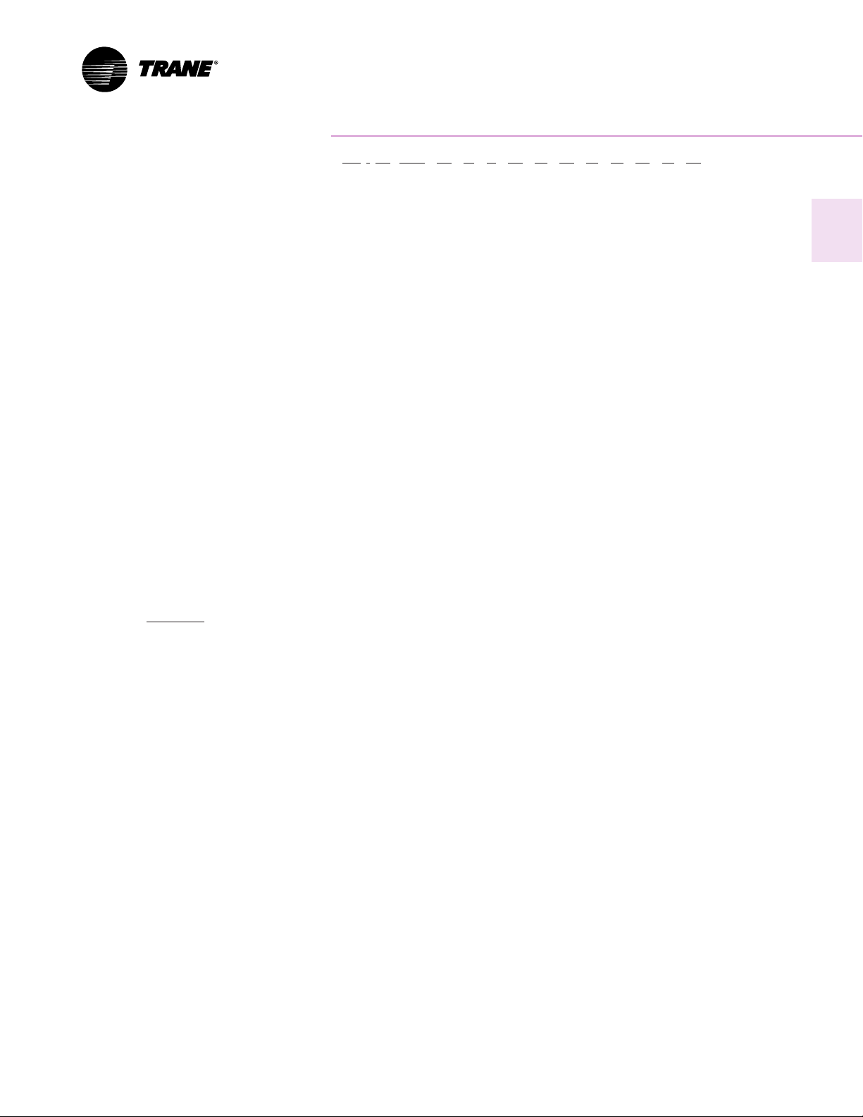
Power Exhaust Fan
The exhaust fan option is a dual, non-
modulating exhaust fan with
approximately half the air-moving
capabilities of the supply fan system.
The experience of The Trane Company
that a non-modulating exhaust fan
selected for 40 to 50 percent of nominal
supply cfm can be applied successfully.
The power exhaust fan generally
should not be selected for more than
40 to 50 percent of design supply
airflow. Since it is an on/off non-
modulating fan, it does not vary
exhaust cfm with the amount of
outside air entering the building.
Therefore, if selected for more than
40 to 50 percent of supply airflow, the
building may become under-
pressurized when economizer
operation is allowing lesser amounts of
outdoor air into the building. If,
however, building pressure is not of a
critical nature, the non-modulating
exhaust fan may be sized for more than
50 percent of design supply airflow.
Barometric Relief Dampers
Barometric relief dampers consist of
gravity dampers which open with
increased building pressure. As the
building pressure increases, the
pressure in the unit return section also
increases, opening the dampers and
relieving air. Barometric relief may be
used to provide relief for single story
buildings with no return ductwork and
exhaust requirements less than
25 percent.
Altitude Corrections
The rooftop performance tables and
curves of this catalog are based on
standard air (.075 lbs/ft) (.034 kg/cm). If
the rooftop airflow requirements are at
other than standard conditions (sea
level), an air density correction is
needed to project accurate unit
performance.
Figure 17-1 shows the air density ratio
at various temperatures and elevations.
Trane rooftops are designed to operate
between 40 and 90°F (4.4 and 32.2°C)
leaving air temperature.
The procedure to use when selecting a
supply or exhaust fan on a rooftop for
elevations and temperatures other than
standard is as follows:
1
First, determine the air density ratio
using Figure 17-1.
2
Divide the static pressure at the
nonstandard condition by the air
density ratio to obtain the corrected
static pressure.
3
Use the actual cfm and the corrected
static pressure to determine the fan
rpm and bhp from the rooftop
performance tables or curves.
4
The fan rpm is correct as selected.
5
Bhp must be multiplied by the air
density ratio to obtain the actual
operating bhp.
In order to better illustrate this
procedure, the following example is
used:
Consider a 29-ton (105 kW) rooftop unit
that is to deliver 9,160 actual cfm (4323
l/s) at 1.50 inches total static pressure
(tsp) (38 mm, 373 Pa), 55°F (12.8°C)
leaving air temperature, at an elevation
of 5,000 ft. (1524 m).
1
From Figure 17-1, the air density ratio
is 0.86.
2
Tsp = 1.50 inches/0.86 = 1.74 inches tsp.
374/.86 = 434 Pa.
3
From the performance tables: a 29-ton
(105 kW) rooftop will deliver 9,160 cfm
at 1.74 inches tsp 4323 l/s at 434 Pa) at
651 rpm and 5.51 bhp (4.11 kW).
4
The rpm is correct as selected
651 rpm.
5
Bhp = 5.51 x 0.86 = 4.74 bhpactual.
kW = 4.11 x 0.86 = 3.5 kW
Compressor MBh, SHR, and kW should
be calculated at standard and then
converted to actual using the correction
factors in Table 17-2. Apply these
factors to the capacities selected at
standard cfm so as to correct for the
reduced mass flow rate across the
condenser.
Heat selections other than gas heat will
not be affected by altitude. Nominal
gas capacity (output) should be
multiplied by the factors given in
Table 17-3 before calculating the
heating supply air temperature.

14
Application
Considerations
Acoustical Considerations
Proper placement of rooftops is critical
to reducing transmitted sound levels to
the building. The ideal time to make
provisions to reduce sound
transmissions is during the design
phase. And the most economical
means of avoiding an acoustical
problem is to place the rooftop(s) away
from acoustically critical areas. If
possible, rooftops should not be
located directly above areas such as:
offices, conference rooms, executive
office areas and classrooms. Instead,
ideal locations might be over corridors,
utility rooms, toilets or other areas
where higher sound levels directly
below the unit(s) are acceptable.
Several basic guidelines for unit
placement should be followed to
minimize sound transmission through
the building structure:
1
Never cantilever the compressor end of
the unit. A structural cross member
must support this end of the unit.
2
Locate the units center of gravity
close to or over column or main
support beam.
3
If the roof structure is very light,
roof joists must be replaced by a
structural shape in the critical areas
described above.
4
If several units are to be placed on one
span, they should be staggered to
reduce deflection over that span.
It is impossible to totally quantify the
effect of building structure on sound
transmission, since this depends on the
response of the roof and building
members to the sound and vibration of
the unit components. However, the
guidelines listed above are experience-
proven guidelines which will help
reduce sound transmissions.
Clearance Requirements
The recommended clearances
identified with unit dimensions should
be maintained to assure adequate
serviceability, maximum capacity and
peak operating efficiency. A reduction
in unit clearance could result in
condenser coil starvation or warm
condenser air recirculation. If the
clearances shown are not possible on a
particular job, consider the following:
Do the clearances available allow for
major service work such as changing
compressors or coils?
Do the clearances available allow for
proper outside air intake, exhaust air
removal and condenser airflow?
If screening around the unit is being
used, is there a possibility of air
recirculation from the exhaust to the
outside air intake or from condenser
exhaust to condenser intake?
Actual clearances which appear
inadequate should be reviewed with a
local Trane sales engineer.
When two or more units are to be
placed side by side, the distance
between the units should be increased
to 150 percent of the recommended
single unit clearance. The units should
also be staggered as shown for two
reasons:
1
To reduce span deflection if more than
one unit is placed on a single span.
Reducing deflection discourages sound
transmission.
2
To assure proper diffusion of exhaust
air before contact with the outside air
intake of adjacent unit.
Duct Design
It is important to note that the rated
capacities of the rooftop can be met
only if the rooftop is properly installed
in the field. A well designed duct
system is essential in meeting these
capacities.
The satisfactory distribution of air
throughout the system requires that
there be an unrestricted and uniform
airflow from the rooftop discharge
duct. This discharge section should be
straight for at least several duct
diameters to allow the conversion of
fan energy from velocity pressure to
static pressure.
However, when job conditions dictate
elbows be installed near the rooftop
outlet, the loss of capacity and static
pressure may be reduced through the
use of guide vanes and proper
direction of the bend in the elbow. The
high velocity side of the rooftop outlet
should be directed at the outside radius
of the elbow rather than the inside.
 Loading...