


 Loading...
Operation
Maintenance
Water Cooled CenTraVac™
With CH530
X39640712050 |
CVHE-SVU01E-EN |
Warnings and
Cautions
Warnings and Cautions
Notice that warnings and cautions appear at appropriate intervals throughout this manual. Warnings are provided to alert installing contractors to potential hazards that could result in personal injury or
death, while cautions are designed to alert personnel to conditions that could result in equipment damage.
Your personal safety and the proper operation of this machine depend upon the strict observance of these precautions.
NOTICE:
Warnings and Cautions appear at appropriate sections throughout this manual.
Read these carefully.
WARNING – Indicates a potentially hazardous situation which, if not avoided, could result in death or serious injury.
CAUTION – Indicates a potentially hazardous situation which, if not avoided, may result in minor or moderate injury. It may also be used to alert against unsafe practices.
CAUTION – Indicates a situation that may result in equipment or property-damage-only accidents.
© 2005 American Standard All rights reserved |
CVHE-SVU01E-EN |

Contents
Warnings and Cautions |
2 |
General Information |
|
4 |
|
Unit Control Panel (UCP) |
|
26 |
|
Operator Interface |
|
28 |
|
Chilled Water Setpoint |
|
41 |
|
Inter Processor Communication (IPC) |
|
49 |
|
Control System Components |
|
50 |
|
Controls Sequence of Operation |
|
63 |
|
Machine Protection and Adaptive Control |
|
68 |
|
Unit Startup |
|
85 |
|
Unit Shutdown |
|
87 |
|
Periodic Maintenance |
|
88 |
|
Oil Maintenance |
|
91 |
|
Maintenance |
|
93 |
|
Forms |
|
100 |
|
|
|
CVHE-SVU01E-EN |
3 |
General
Information
Literature change
Applicable to CVHE, CVHF, CVHG
About this manual
Operation and maintenance information for models CVHE, CVHF and CVHG are covered in this manual. This includes both 50 and 60 Hz. CVHE, CVHF and CVHG centrifugal chillers equipped with the Tracer CH530 Chiller Controller system. Please note that information pertains to all three chiller types unless differences exist in which case the sections are broken down by Chiller type as applicable and discussed separately.
By carefully reviewing this information and following the instructions given, the owner or operator can successfully operate and maintain a CVHE, CVHF or CVHG unit.
If mechanical problems do occur, however, contact a qualified service organization to ensure proper diagnosis and repair of the unit.
Note: The CH530 controller was first applied to CVHE with Design Sequence “3K”, and to CVHF with Design Sequence “1W”.
Unit Nameplate
The unit nameplate is located on the left side of the unit control panel.
The following information is provided on the unit nameplate.
1. Serial Number
The unit serial number provides the specific chiller identity. Always provide this serial number when calling for service or during parts identification..
2. Service Model Number
The service model represents the unit as built for service purposes . It identifies the selections of variable unit features required when ordering replacements parts or requesting service.
Note: Unit-mounted starters are identified by a separate number found on the starter.
3. Product Coding Block
The CVHE, CVHF and CVHG models are defined and built using the product definition and selection (PDS) system. This system describes the product offerings in terms of a product coding block which is made up of feature categories and feature codes. An example of a typical product code block is given on this page. The coding block precisely identifies all characteristics of a unit.
4.Identifies unit electrical requirements
5.Correct operating charges and type of refrigerant
6.Unit Test Pressures and Maximum Operating Pressures
7.Identifies unit Installation and Operation and Maintenance manuals
8.Drawing numbers for Unit Wiring Diagrams
Typical Product Description Block
MODL CVHE |
DSEQ 2R |
NTON 320 |
VOLT 575 |
REF 123 |
HRTZ 60 |
TYPE SNGL |
CPKW 142 |
CPIM 222 |
TEST AIR |
EVTM IECU |
EVTH 28 |
EVSZ 032S |
EVBS 280 |
|
EVWC STD |
EVWP 2 |
EVWT NMAR |
EVPR 150 |
|
EVCO VICT |
EVWA LELE |
CDTM IECU |
CDTH 28 |
|
CDSZ 032S |
CDBS 250 |
CDWC STD |
CDWP 2 |
|
CDWT NMAR |
CDPR 150 |
CDCO VICT |
CDWA LELE |
|
CDTY STD |
TSTY STD |
ECTY WEOR |
ORSZ 230 |
|
PURG PURE |
WCNM SNMP |
SPKG DOM |
OPTI CPDW |
|
HHOP NO |
GENR NO |
GNSL NO |
SOPT SPSH |
|
ACCY ISLS |
HGBP WO |
LUBE SNGL |
AGLT CUL |
|
CNIF UCP |
SRTY USTR |
SRRL 207 |
PNCO TERM |
|
4 |
CVHE-SVU01E-EN |

General
Information
An example of a typical model number is:
CVHF091NAL00ACU2758W7E8TB
C0000000K01G14C10W1A03B1
Model Number Digit Identification C = (1st digit) CenTraVac® Hermetic V = (2nd digit) CenTraVac® Hermetic H = (3rd digit) Direct Drive
F = (4th digit) Development sequence
091 = (5th, 6th, and 7th digit) Nominal compressor tonnage
N = (8th digit) Unit Voltage
A = (9th digit) Unit Type
A = Cooling Condenser
B = Heat Recovery Condenser C = Auxiliary Condenser
D = Free Cooling Option S = Special
L0 = (10th and 11th digit) Design Sequence
0 = (12th digit) Hot Gas By-Pass
W = With HGB
0 = Without HGB
S = Special
A = (13th) Starter type
A = Star-Delta Unit Mounted
C = Star Delta – Remote Mounted E = X-Line Full Volt – Remote Mounted
F = Autotransformer – Remote Mounted
G = Primary Reactor – Remote Mounted
H = X-Line Full Volt – Unit Mounted J = Autotransformer – Unit Mounted
K = Primary Reactor – Unit Mounted
L = Solid State – Unit Mounted M = Solid State – Floor Mounted N = Solid State – Wall Mounted
P = Adaptive Frequency Drive - Unit Mounted
R = Customer Supplied
C = (14th digit) Control Enclosure S = Special
C = Standard Control Enclosure
U = (15th digit) Compressor Motor Power (kw)
275 = (16th, 17th, and 18th digit) Compressor Imp Cutback
8 = (19th digit) Evaporator Shell Size
W = (20th digit) Evaporator Tube Bundle
7 = (21st digit) Evaporator Tubes
E = (22nd digit) Evaporator Waterbox
8 = (23rd digit) Condenser Shell Size
T = (24th digit) Condenser Tube Bundle
B = (25th digit) Condenser Tubes
C = (26th digit) Condenser
Waterboxes
0 = (27th digit) Heat Recovery Condenser Shell Size
0 = (28th digit) Heat Recovery Condenser Tube Bundle
0 = (29th digit) Heat Recovery Condenser Tubes
0 = (30th digit) Heat Recovery Condenser Waterboxes
0 = (31st digit) Auxiliary Condenser Size and Waterboxes
0 = (32nd digit) Auxiliary Condenser Tubes
0 = (33rd digit) Orifice Size
K = (34th digit) Orifice Size
0 = (35th digit) Unit Option
1 = (36th digit) Control: Enhanced protection
G = (37th digit) Control: Generic BAS
1 = (38th digit) Control: Extended operation
4 = (39th digit) Tracer communication interface
C = (40th digit) Control: Condenser refrigerant pressure
1 = (41st digit) Control: Tracer IO
0 = (42nd digit) Special Options
W = (43nd digit) Control: Water flow control
1 = (44th digit) Control: Chilled water reset
A = (45th digit) Control: Heat Recovery temperature sensors
0 = (46th digit) Gas Powered Chiller
3 = (47th digit) Compressor Motor Frame Size
B = (48th digit) Volute Discharge Angle
1 = (49th digit) Control: Operating status
W = (50th digit) Industrial Chiller Package (INDP)
0 = Without INDP
W = With INDP
1 = (51st digit) Control Power Transformer (CPTR)
0 = Without CPTR
1 = With CPTR S = Special
B = (52nd digit) Motor and Terminal Board Configuration
A = Six Lead Low Voltage
B = Three Lead Medium Voltage
C = Six Lead Medium Voltage
S = Special
CVHE-SVU01E-EN |
5 |

General
Information
Commonly Used Acronyms
For convenience, a number of acronyms are used throughout this manual. These acronyms are listed alphabetically below, along with the “translation” of each:
AFD = Adaptive Frequency Drive
ASME = American Society of
Mechanical Engineers
ASHRAE = American Society of
Heating, Refrigerating and Air
Conditioning Engineers
BAS = Building Automation System
CABS = Auxiliary Condenser Tube-
Bundle S
CDBS = Condenser Bundle Size
CDSZ = Condenser Shell Size
CH530 = Tracer CH530 Controller
DV = DynaView™ Clear Language Display, also know as the Main Processor (MP)
CWR = Chilled Water Reset
CWR’ = Chilled Water Reset Prime
DTFL = Design Delta-T at Full Load (i.e., the difference between entering and leaving chilled water temperatures)
ELWT = Evaporator Leaving Water
Temperature
ENT = Entering Chilled Water
Temperature
FC = Free Cooling
GPM = Gallons-per-minute
HGBP = Hot Gas Bypass
HVAC = Heating, Ventilating, and Air
Conditioning
IE = Internally-Enhanced Tubes
IPC = Interprocessor Communication
LBU = La Crosse Business Unit
LCD = Liquid Crystal Display
LED = Light Emitting Diode
MAR = Machine Shutdown Auto Restart (Non-Latching where chiller will restart when condition corrects itself.)
MMR = Machine Shutdown Manual Restart (Latching where chiller must be manually reset.)
MP = Main Processor
PFCC = Power Factor Correction
Capacitor
PSID = Pounds-per-Square-Inch (differential pressure)
PSIG = Pounds-per-Square-Inch (gauge pressure)
UCP = Unit Control Panel
LLID = Low Level Intelligent Device (Sensor, Pressure Transducer, or Input/output UCP module)
RLA = Rated Load Amps
RTD = Resistive Temperature Device
Tracer CH530= Controls Platform utilized on this Chiller
TOD = Temperature Outdoor
Control Optional Packages
OPST Operating Status Control
GBAS Generic Building Automation
Interface
EXOP Extended Operation
CDRP Condenser Pressure
Transducer
TRMM Tracer Communications
FRCL Free Cooling
HGBP Hot Gas Bypass
WPSR Water pressure sensing
EPRO Enhanced Protection
ACOS Auxillary Condenser sensors
CWR Chiller Water reset outdoor
6 |
CVHE-SVU01E-EN |
General
Information
Overview
CVHE, CVHG, CVHF
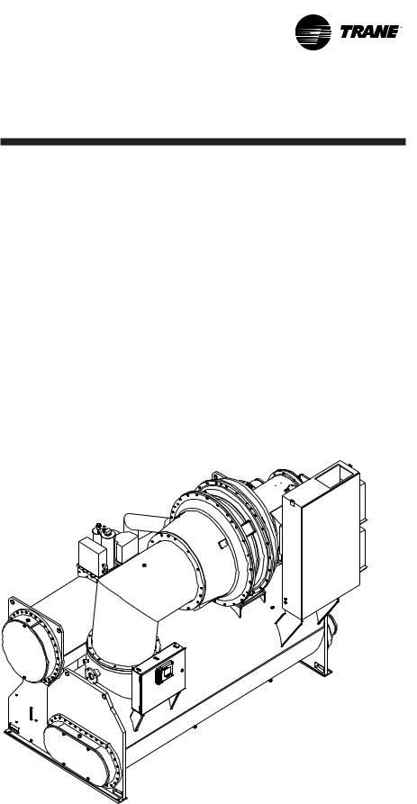
Each CVHE, CVHG, or CVHF unit is composed of 5 basic components.
—the evaporator,
—3-stage compressor on CVHE, CVHG or 2 stage compressor on CVHF,
—2-stage economizer on CVHE, CVHG, or single economizer on
CVHF,
See Figure 1 for Typical CVHE and CVHG, and Figure 2 for Typical CVHF major components.
A heat-recovery or auxiliary condenser can be factory-added to the basic unit assembly to provide a heat-recovery cycle.
—water-cooled condenser,
—related interconnecting piping.
Figure 1. General CVHE and CVHG unit components
CVHE-SVU01E-EN |
7 |

General
Information
Figure 1. General CVHE and CVHG unit components - continued
8 |
CVHE-SVU01E-EN |
General
Information
Figure 2. Illustrates the general component layout of a typical CVHF chiller
CVHE-SVU01E-EN |
9 |

General
Information
Cooling Cycle
CVHE, CVHG, CVHF
When in the cooling mode, liquid refrigerant is distributed along the length of the evaporator and sprayed through small holes in a distributor (i.e., running the entire length of the shell) to uniformly coat each evaporator tube. Here, the liquid refrigerant absorbs enough heat from the system water circulating through the evaporator tubes to vaporize.
The gaseous refrigerant is then drawn through the eliminators (which remove droplets of liquid refrigerant from the gas) and firststage variable inlet guide vanes, and into the first stage impeller.
Note: Inlet guide vanes are designed to modulate the flow of gaseous refrigerant to meet system capacity requirements; they also prerotate the gas, allowing it to enter the impeller at an optimal angle that maximizes efficiency at all load conditions.
CVHE, CVHG Compressor
Compressed gas from the first-stage impeller flows through the fixed, second-stage inlet vanes and into the second-stage impeller.
Here, the refrigerant gas is again compressed, and then discharged through the third-stage variable guide vanes and into the third stage impeller.
Once the gas is compressed a third time, it is discharged into the
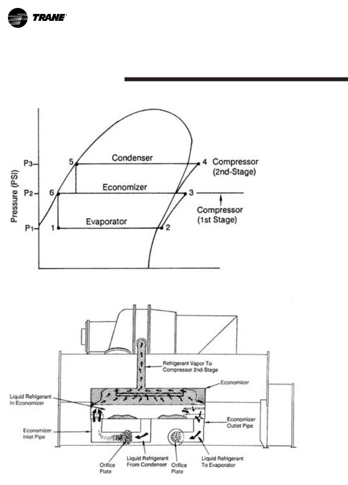
condenser. Baffles within the condenser shell distribute the compressed refrigerant gas evenly across the condenser tube bundle. Cooling tower water circulated through the condenser tubes absorbs heat from the refrigerant, causing it to condense. The liquid refrigerant then passes through orifice plate ‘‘A’’ and into the economizer.
The economizer reduces the energy requirements of the refrigerant cycle by eliminating the need to pass all gaseous refrigerant through three stages of compression. See Figure 3. Notice that some of the liquid refrigerant flashes to a gas because of the pressure drop created by the orifice plates, thus further cooling the liquid refrigerant. This flash gas is then drawn directly from the first (Chamber A) and second (Chamber B) stages of the economizer into the third-and second-stage impellers of the compressor, respectively.
All remaining liquid refrigerant flows through another orifice plate ‘‘C’’ to the evaporator.
CVHF Compressor
Compressed gas from the first-stage impeller is discharged through the second-stage variable guide vanes and into the second-stage impeller. Here, the refrigerant gas is again compressed, and then discharged into the condenser.
Baffles within the condenser shell distribute the compressed refrigerant gas evenly across the condenser tube bundle. Cooling tower water, circulated through the condenser tubes, absorbs heat from the refrigerant, causing it to condense. The liquid refrigerant then flows out of the bottom of the condenser, passing through an orifice plate and into the economizer.
The economizer reduces the energy requirements of the refrigerant cycle by eliminating the need to pass all gaseous refrigerant through both stages of compression. See Figure 6. Notice that some of the liquid refrigerant flashes to a gas because of the pressure drop created by the orifice plate, thus further cooling the liquid refrigerant. This flash gas is then drawn directly from the economizer into the second-stage impellers of the compressor.
All remaining liquid refrigerant flows out of the economizer, passes through another orifice plate and into the evaporator.
10 |
CVHE-SVU01E-EN |
General
Information
Figure 3. CVHE, CVHG pressure enthalpy curve
Figure 4. CVHE, CVHG 2-stage economizer
CVHE-SVU01E-EN |
11 |
General
Information
Figure 5. CVHF pressure enthalpy curve
Figure 6. CVHF single stage economizer
12 |
CVHE-SVU01E-EN |
General
Information
Overview
Controls Operator Interface
Information is tailored to operators, service technicians and owners
When operating a chiller, there is specific information you need on a day-to-day basis — setpoints, limits, diagnostic information, and reports.
When servicing a chiller, you need different information and a lot more of it — historic and active diagnostics, configuration settings, and customizable control algorithms, as well as operation settings.
By providing two different tools – one for daily operation and one for periodic service — everyone has easy access to pertinent and appropriate information.
DynaView™ Human Interface
— For the operator
Day-to-day operational information is presented at the panel. Up to seven lines of data (English or SI units) are simultaneously displayed on the ¼ VGA touch-sensitive screen. Logically organized groups of information — chiller modes of operation, active diagnostics, settings and reports put information conveniently at your fingertips. See Operator Interface Section for details.
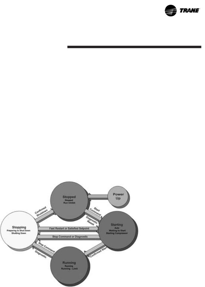
Figure 7. CVHE, CVHF, and CVHG sequence of operation overview
TechView™ Chiller Service Tool
— For the service technician or advanced operator
All chiller status, machine configuration settings, customizable limits, and up to 60 active or historic diagnostics are displayed through the service tool interface. Without changing any hardware, we give you access to the latest and greatest version of Tracer CH530! A new level of serviceability using the innovative TechView™ chiller service tool, a technician can interact with an individual device or a group of devices for advanced troubleshooting. LED lights and their respective TechView™ indicators visually confirm the viability of each device. Any PC that meets the system requirements may download the service interface software and Tracer CH530 updates. For more information on TechView™ visit your local Trane Service company, or The Trane Company’s website at www.trane.com.
CVHE-SVU01E-EN |
13 |
General
Information
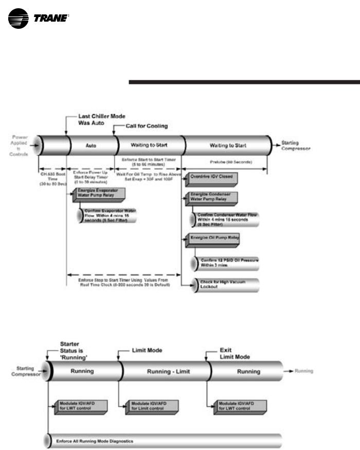
Figure 8. CVHE, CVHF, and CVHG sequence of operation: power up to starting
Figure 9. CVHE, CVHF, and CVHG sequence of operation: running
14 |
CVHE-SVU01E-EN |
General
Information
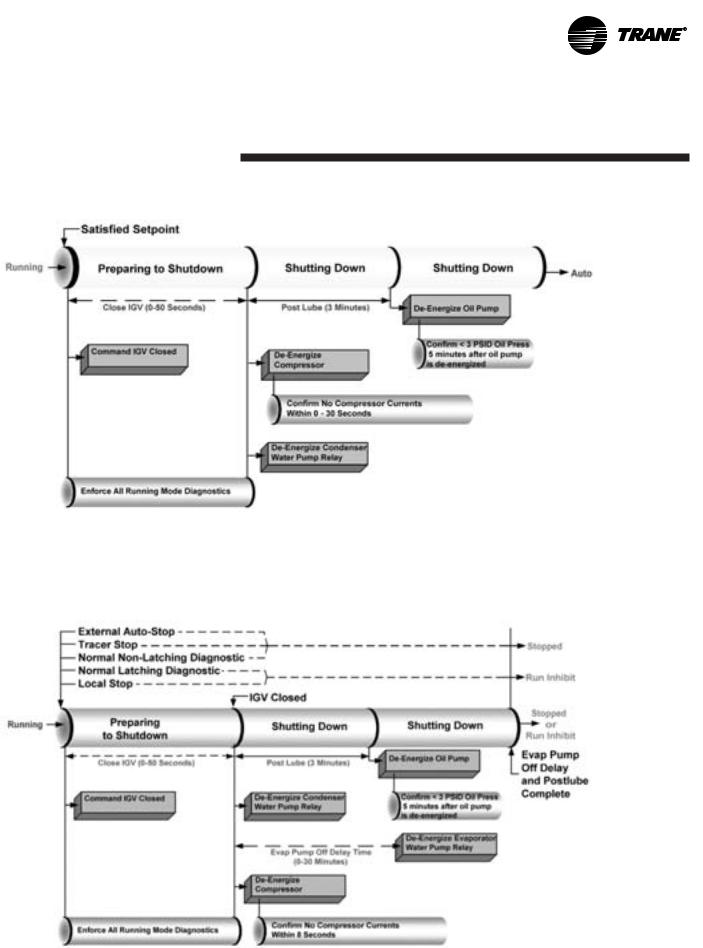
Figure 10. CVHE, CVHF, and CVHG sequence of operation: satisfied setpoint
Figure 11. CVHE, CVHF and CVHG sequence of operation: normal shutdown to stopped and run inhibit
CVHE-SVU01E-EN |
15 |

General
Information
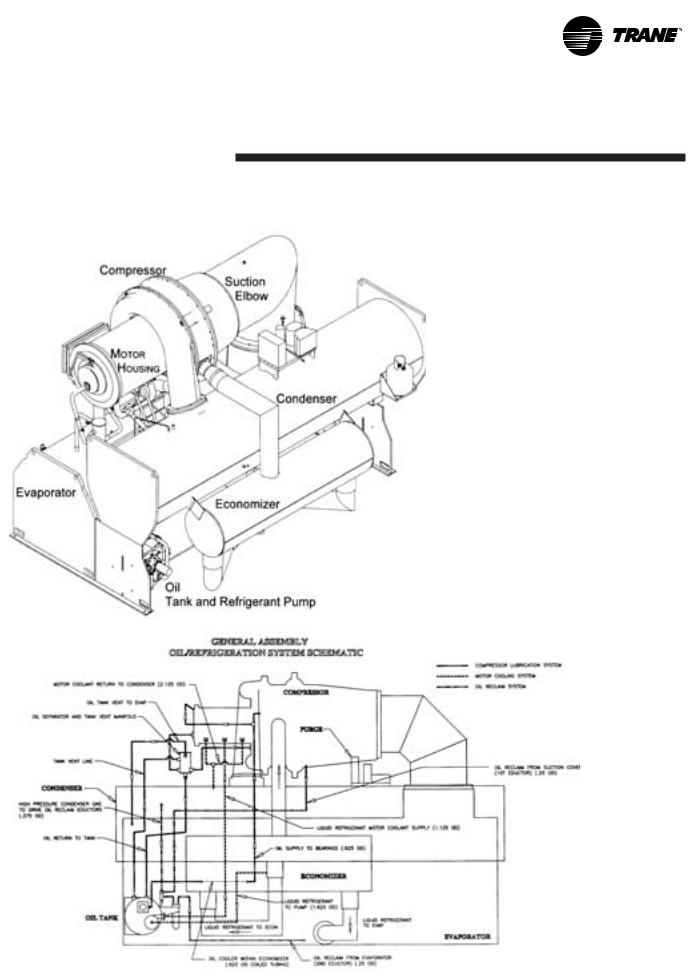
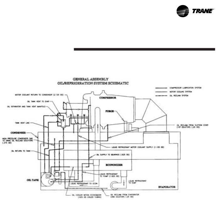
Oil and Refrigeration Pump
Compressor Lubrication System -
A schematic diagram of the compressor lubrication system is illustrated in Figure 12.
Oil is pumped from the oil tank (by a pump and motor located within the tank) through an oil pressureregulating valve designed to maintain a net oil pressure of 18 to 22 psid. It is then filtered and sent to the oil cooler located in the economizer and on to the bearings. From the bearings, the oil drains back to the manifold under the motor and then on to the oil tank.
CAUTION
Surface Temperatures!
MAY EXCEED 150°F. Use caution while working on certain areas of the unit, failure to do so may result in minor or moderate injury.
To ensure proper lubrication and prevent refrigerant from condensing in the oil tank, a 750-watt heater is immersed in the oil tank and is used to warm the oil while the unit is off. When the unit starts, the oil heater is de-energized. This heater energizes as needed to maintain 140° to 145° F (60-63°C) when the chiller is not running.
When the chiller is operating, the temperature of the oil tank is typically 115° to 160°F (46-72°C). The oil return lines from the thrust and journal bearings, transport oil and some seal leakage refrigerant. The oil return lines are routed into a manifold under the motor. Gas flow exits the top of the manifold and is vented to the Evaporator. A vent line solenoid is not needed with the refrigerant pump. Oil exits the bottom of the manifold and returns to the tank. Separation of the seal leakage gas in the manifold keeps this gas out of the tank.
A dual eductor system is used to reclaim oil from the suction cover and the evaporator, and deposit it back into the oil tank. These eductors use high pressure condenser gas to draw the oil from the suction cover and evaporator to the eductors and then discharged into the oil tank. The evaporator eductor line has a shut off valve mounted by the evaporator and ships closed. Open two turns if necessary.
Liquid refrigerant is used to cool the oil supply to both the thrust bearing and journal bearings. On refrigerant pump units the oil cooler is located inside the economizer and uses refrigerant passing from the condenser to evaporator to cool the oil. Oil leaves the oil cooler and flows to both the thrust and journal bearings.
Motor Cooling System
Compressor motors are cooled with liquid refrigerant, see Figure 12.
The refrigerant pump is located on the front of the oil tank (motor inside the oil tank). The refrigerant pump inlet is connected to the well at the bottom of the condenser. The connection is on the side where a weir assures a preferential supply of liquid. Refrigerant is delivered to the motor via the pump. Motor refrigerant drain lines are routed to the condenser.
16 |
CVHE-SVU01E-EN |
General
Information
Figure 12. Oil refrigerant pump
CVHE-SVU01E-EN |
17 |

General
Information
Base Loading Control Algorithm:
This feature allows an external controller to directly modulate the capacity of the chiller. It is typically used in applications where virtually infinite sources of evaporator load and condenser capacity are available and it is desirable to control the loading of the chiller. Two examples are industrial process applications and cogeneration plants. Industrial process applications might use this feature to impose a specific load on the facility’s elecrical system.
Cogeneration plants might use this feature to balance the system’s heating, cooling and electrical generation.
All chiller safeties and adaptive control functions are in full effect when Base Loading control is enabled. If the chiller approaches full current, the evaporator temperature drops too low, or the condenser pressure rises too high, Tracer CH530 Adaptive Control logic limits the loading of the chiller to prevent the chiller from shutting down on a safety limit. These limits may prevent the chiller from reaching the load requested by the Base Loading signal.
Base Loading Control is basically a variation of the current limit algorithm. During base loading, the leaving water control algorithm provides a load command every 5 seconds. The current limit routine may limit the loading when the current is below setpoint. When the current is within the deadband of the setpoint the current limit algorithm holds against this loading command.
If the current exceeds the setpoint, the current limit algorithm unloads. The “Capacity Limited By High Current” message normally displayed while the current limit routine is active is suppressed while base loading.
Base loading can occur via Tracer, External signal, or front panel.
Tracer Base Loading: Current Setpoint Range: (20 - 100) percent RLA
Requires Tracer and Optional Tracer Communications Module (LLID)
The Tracer commands the chiller to enter the base load mode by sending the base load mode request. If the chiller is not running, it will start regardless of the differential to start (either chilled water or hot water). If the chiller is already running, it will continue to run regardless of the differential to stop (either chilled water or hot water), using the base load control algorithm. While the unit is running in base loading, it will report that status back to the Tracer by setting “Base Load Status = true” in the Tracer Status Byte. When the Tracer removes the base load mode request (sets the bit to 0). The unit will continue to run, using the normal chilled or hot water control algorithm, and will turn off, only when the differential to stop has been satisfied.
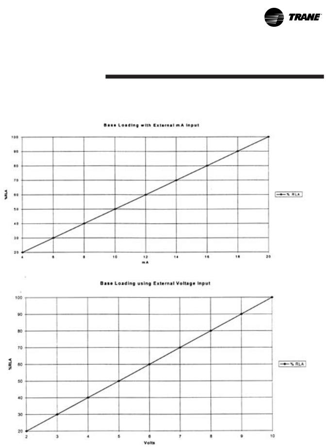
External Base Loading: Current Setpoint Range: (20 - 100) percent RLA
The UCP accepts 2 inputs to work with external base loading. The binary input is at 1A18 Terminals J2-1 and J2-2 (Ground) which acts as a switch closure input to enter the base-loading mode. The second
input, an analog input, is at 1A17 terminals J2 – 1 and 3 (Ground) which sets the external base loading setpoint, and can be controlled by either a 2-10Vdc or 4-20ma Signal. At startup the input type is configured. The graphs in Figure 13 show the relationship between input and percent RLA. While in base loading the active current limit setpoint is set to the Tracer or external base load setpoint, providing that the base load setpoint is not equal to 0 (or out of range). If it is out of range, the front panel current limit setpoint is used. During base loading, all limits are enforced with the exception of current limit. The human interface displays the message “Unit is Running Base Loaded”. Hot Gas Bypass is not run during base loading. If base loading and ice making are commanded simultaneously, ice making takes precedence.
An alternative and less radical approach to Base Loading indirectly controls chiller capacity. Artifically load the chiller by setting the chilled water setpoint lower than it is capable of achieving. Then, modify the chiller’s load by adjusting the current limit setpoint. This method provides greater safety and control stability in the operation of the chiller because it has the advantage of leaving the chilled water temperature control logic in effect. The chilled water temperature control logic responds quicker to dramatic system changes, and can limit the chiller loading prior to reaching an Adaptive Control limit point.
18 |
CVHE-SVU01E-EN |
General
Information
Figure 13. Base loading with external mA input and with external voltage input
CVHE-SVU01E-EN |
19 |
General
Information
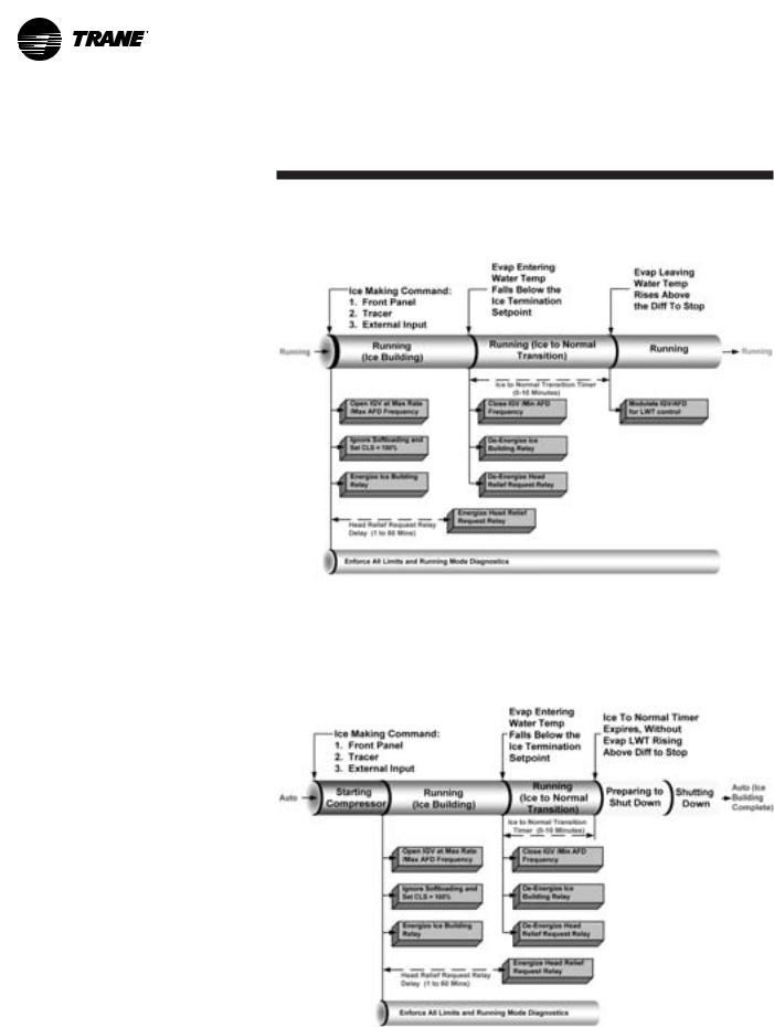
Ice Machine Control
The control panel provides a service level “Enable or Disable” menu entry for the Ice Building feature when the Ice Building option is installed. Ice Building can be entered 1) from the “Front Panel”, 2) if hardware is specified, will accept either an isolated contact closure (1A19 Terminals J2-1 and J2-2 (Ground) ) 3), a remote communicated input (Tracer) to initiate the ice building mode where the unit runs fully loaded at all times. Ice building will be terminated either by opening the contact or based on entering evaporator fluid temperature. UCP will not permit the Ice Building mode to be entered again until the unit is switched to the Non-ice building mode and back into the ice building mode. It is not acceptable to reset the chilled water setpoint low to achieve a fully loaded compressor. When entering ice-building the compressor will be loaded at its maximum rate and when leaving ice building the compressor will be unloaded at its maximum rate. While loading and unloading the compressor, all surge detection will be ignored. While in the ice building mode, current limit setpoints less than the maximum will be ignored. Ice Building can be terminated by one of the following means:
1.Front Panel Disable, or
2.Opening the external Ice. Contacts/ Remote communicated input (Tracer), or
3.Satisfying an evaporator entering fluid temperature setpoint (Default to 27°F).
4.Surging for 7 minutes at full open IGV.
Figure 14. CVHE, CVHF and CVHG sequence of operation: ice making: running to ice making
Figure 15. CVHE, CVHF and CVHG sequence of operation: ice making: stopped to ice to ice building complete
20 |
CVHE-SVU01E-EN |
General
Information
Free Cooling Cycle
Based on the principle that refrigerant migrates to the coldest area in the system, the free cooling option adapts the basic chiller to function as a simple heat exchanger. However, it does not provide control of the leaving chilled water temperature.
If condenser water is available at a temperature lower than the required leaving chilled water temperature, the operator interface must remain in “AUTO” and the operator starts the free cooling cycle by enabling the Free cooling mode in the “DynaView™ Feature Settings” group of the operator interface, or by means of a Tracer request.
Several components must be factoryinstalled or field-installed to equip the unit for free cooling operation:
—a refrigerant gas line, and electrically-actuated shutoff valve, between the evaporator and condenser;
—a valve liquid return line, and electrically-actuated shutoff valve, between the condenser sump and the evaporator;
—a liquid refrigerant storage vessel (larger economizer); and,
—additional refrigerant.
When the chiller is changed over to the free cooling mode, the compressor will shut down if running, the shutoff valves in the liquid and gas lines open; unit control logic prevents the compressor from energizing during free cooling. Liquid refrigerant then drains (by gravity) from the storage tank into the evaporator and floods the tube bundle. Since the temperature and pressure of the refrigerant in the evaporator are higher than in the condenser (i.e., because of the difference in water temperature), the refrigerant in the evaporator vaporizes and travels to the condenser. Cooling tower water causes the refrigerant to condense, and it flows (again, by gravity) back to the evaporator.
This compulsory refrigerant cycle is sustained as long as a temperature differential exists between condenser and evaporator water. The actual cooling capacity provided by the free cooling cycle is determined by the difference between these temperatures which, in turn, determines the rate of refrigerant flow between the evaporator and condenser shells.
If the system load exceeds the available free cooling capacity, the operator must manually initiate changeover to the mechanical cooling mode by disabling the free cooling mode of operation. The gas and liquid line valves then close and compressor operation begins. (See Figure 8 beginning at “Auto” mode.) Refrigerant gas is drawn out of the evaporator by the compressor, where
CVHE-SVU01E-EN |
21 |

General
Information
it is then compressed and discharged to the condenser. Most of the condensed refrigerant initially follows the path of least resistance by flowing into the storage tank. This tank is vented to the economizer sump through a small bleed line; when the storage tank is full, liquid refrigerant must flow through the bleed line restriction. Because the pressure drop through the bleed line is greater than that of the orifice flow control device, the liquid refrigerant flows normally from the condenser through the orifice system and into the economizer.
Free Cooling FRCL
To enable Free Cooling Mode:
1.Free Cooling must first be installed and commissioned.
2.Enable the Free Cooling mode in the DynaView™ Settings Menu
3.Press “AUTO”, and if used, close the external binary input switch (connected to 1A20 J2- 1 to 2) while the chiller is in “AUTO”.
Free Cooling cannot be entered if the chiller is in “STOP”.
If the chiller is in “AUTO” and not running, the condenser water pump will start. After condenser water flow is proven, Relay Module 1A11 will energize operating the Free Cooling Valves 4B12 and 4B13. The Free Cooling Valves End Switches must open within 3 minutes, or an MMR diagnostic will be generated. Once the Free Cooling Valves End Switches open, the unit is in the Free Cooling mode. If the chiller is in “AUTO” and running powered cooling, the chiller will do a friendly shut down first, (Run: Unload, Post Lube, and drive vanes closed). After the vanes have been overdriven, closed and condenser water proven, the Free Cooling relays will be
energized. To disable Free Cooling and return to Powered Cooling, either disable the Free Cooling Mode in the DynaView™ settings menu if used to enable Free Cooling or “OPEN” the external binary input switch to the 1A20 Module if it was used to enable Free Cooling. Once Free Cooling is disabled, the Free Cooling relays
Relay Module 1A11 will de-energize allowing the Free Cooling valves to close. The Free Cooling valves end switches must close within 3 minutes or an MMR diagnostic is generated. Once the end switches close the chiller will return to “AUTO” and powered cooling will resume if there is a call for cooling based on the differential to start.
Note: The manual control of the inlet guide vanes is disabled while in the Free Cooling Mode and the compressor is prevented from starting by the control logic.
Note: The relay at 1A11-J-2-4 to 6 is a FC auxiliary relay and can be used as required.
22 |
CVHE-SVU01E-EN |

General
Information
Hot Gas Bypass
The hot gas bypass (HGBP) control option is designed to minimize machine cycling by allowing the chiller to operate stably under minimum load conditions. In these situations, the inlet guide vanes are “locked” at a preset minimum position, and unit capacity is governed by the HGBP valve actuator. Control circuitry is designed to allow both the inlet guide vanes and the HGBP valve to close for unit shutdown.
After a chiller starts and is running the inlet guide vanes will pass through the HGBP Cut-In-Vane position as the chiller starts to load. As the chiller catches the load and starts to unload, the inlet guide vanes will close to the HGBP Cut-In Vane position. At this point the movement of the inlet guide vanes is frozen and further unloading of the chiller is controlled by the opening of the HGBP Valve 4M5 and module modulates the HGBP valve at low loads. When the control algorithm determines the chiller to be shut down, the inlet guide vanes will be driven fully closed, and the HGBP
valve will be driven closed. After the inlet guide vanes are fully closed the chiller will shut down in the Friendly mode. Chillers with HGBP have a discharge temperature sensor (4R16) monitoring the discharge gas temperature from the compressor. If this temperature exceeds 200°F, the chiller will shut off on a MAR diagnostic. The chiller will reset automatically when this temperature drops 50°F below the trip-point.
HGBP is enabled in the Features menu settings Group of the DV Menus by enabling the option. The setting the HGBP Cut-In Vane Position is setup at unit commissioning via the service tool.
CVHE-SVU01E-EN |
23 |

General
Information
Hot Water control
Occasionally CTV chillers are selected to provide heating as a primary mission. With hot water temperature control, the chiller can be used as a heating source or cooling source. This feature provides greater application flexibility. In this case the operator selects a hot water temperature and the chiller capacity is modulated to maintain the hot water setpoint. Heating is the primary mission and cooling is a waste product or is a secondary mission. This type of operation requires an endless source of evaporator load (heat), such as well or lake water. The chiller has only one condenser.
Note: Hot water temperature control mode does not convert the chiller to a heat pump. Heat pump refers to the capability to change from a coolingdriven application to a heating-driven application by changing the refrigerant path on the chiller. This is impractical for centrifugal chillers as it would be much easier to switch over the water side.
This is NOT heat recovery. Although this feature could be used to recover heat in some form, there is a second heat exchanger on the condenser side.
The DynaView™ Main Processor provides the hot water temperature control mode as standard. The leaving condenser water temperature is controlled to a hot water setpoint between 80 and 140°F (26.7 to 60°C) The leaving evaporator water temperature is left to drift to satisfy the heating load of the condenser. In this application the evaporator is normally piped into a lake, well, or other source of constant temperature water for the purpose of extracting heat.
In hot water temperature control mode all the limit modes and diagnostics operate as in normal cooling with one exception; The leaving condenser water temperature sensor is an MMR diagnostic when in hot water temperature control mode. (It is an informational warning in the normal cooling mode.)
In the hot water temperature control mode the differential-to-start and differential-to-stop setpoints are used with respect to the hot water setpoint instead of with the chilled water setpoint.
UCP provides a separate entry at the DV to set the hot water setpoint. Tracer is also able to set the hot water setpoint. In the hot water mode the external chilled water setpoint is the external hot water setpoint; that is, a single analog input is shared at the 1A16 –J2-1 to J2-3 (ground)
An external binary input to select external hot water control mode is on the EXOP OPTIONAL module 1A18 terminals J2-3 to J2-4 (ground). Tracer also has a binary input to select chilled water control or hot water temperature control.
There is no additional leaving hot water temperature cutout; the HPC and condenser limit provide for high temperature and pressure protection.
In hot water temperature control the softloading pulldown rate limit operates as a softloading pullup rate limit. The setpoint for setting the temperature rate limit is the same setpoint for normal cooling as it is for hot water temperature control.
The hot water temperature control feature is not designed to run with HGBP, AFD, free cooling, or ice making.
The factory set PID tuning values for the leaving water temperature control are the same settings for both normal cooling and hot water temperature control.
24 |
CVHE-SVU01E-EN |

General
Information
Heat Recovery Cycle
‘‘Heat recovery’’ is designed to salvage the heat that is normally rejected to the atmosphere through the cooling tower, and put it to beneficial use. For example, a highrise office building may require simultaneous heating and cooling during the winter months. With the addition of a heat recovery cycle, heat removed from the building cooling load can be transferred to areas of the building that require heat. (Keep in mind that the heat recovery cycle is only possible if a cooling load exists to act as a heat source.)
To provide a heat recovery cycle, a heat-recovery condenser is added to the unit; see Figure 2. Though physically identical to the standard cooling condenser, the heat-recovery condenser is piped into a heat circuit rather than to the cooling tower. During the heat recovery cycle, the unit operates just as it does in the ‘‘cooling only’’ mode except that the cooling load heat is rejected to the heating water circuit rather than to the cooling tower water circuit. When hot water is required, the heating water circuit pumps energize. Water circulated through the heat-recovery (or auxiliary) condenser tube bundle by the pumps absorbs cooling-load from the compressed refrigerant gas discharge by the compressor. The heated water is then used to satisfy heating requirements.
Auxiliary Condensers
Unlike the heat-recovery condenser (which is designed to satisfy comfort heating requirements), the auxiliary condenser serves a preheat function only, and is used in those applications where hot water is needed for use in kitchens, lavatories, etc. While the operation of the auxiliary condenser is physically identical to that of the heat-recovery condenser, it is comparatively smaller in size, and its heating capacity is not controlled.
Trane does not recommend operating the auxiliary condenser alone because of its small size.
CVHE-SVU01E-EN |
25 |
Unit Control
Panel (UCP)
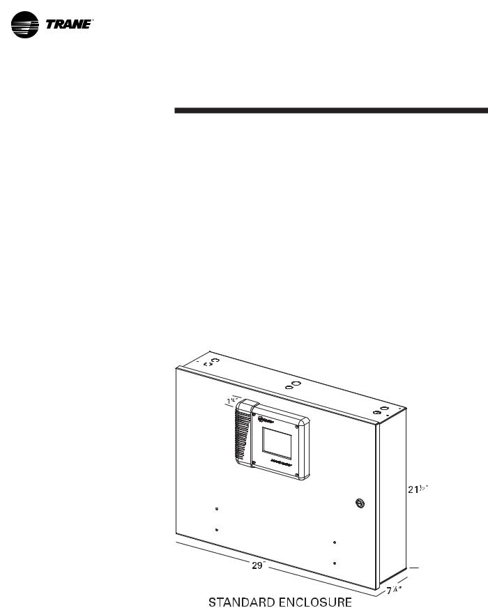
Control Panel Devices and Unit
Mounted Devices
Unit Control Panel (UCP)
Safety and operating controls are housed in the unit control panel, the starter panel and the purge control panel. The UCP ‘s operator interface and main processor is called the DynaView™ (DV) and is located on the UCP door. (See Operators interface section for detailed information)
The UCP houses several other controls modules called panel mounted LLID (Low Level Intelligent Device), power supply, terminal block, fuse, circuit breakers, and transformer. The IPC (Interprocessor communication) bus allows the communications between LLID’s and the main processor. Unit mounted devices are called frame mounted LLID’s and can be temperature sensors or pressure transducers. These and other functional switches provide analog and binary inputs to the control system.
Figure 16. Control panel and approximate dimensions
26 |
|
|
|
|
|
|
|
|
|
|
|
|
|
|
|
|
|
|
|
|
CVHE-SVU01E-EN |
|
|
|
|
|
|
|
|
|
|
|
|
|
|
|
|
|
|
|
|
||
|
|
|
|
|
|
|
|
|
|
|
|
|
|
|
|
|
|
|
|
||
|
|
|
|
|
|
|
|
|
|
|
|
|
|
|
|
|
|
|
|
||
|
|
|
|
|
|
|
|
|
|
|
|
|
|
|
|
|
|
|
|
||
|
|
|
|
|
|
|
|
|
|
|
|
|
|
|
|
|
|
|
|
||
|
|
|
|
|
|
|
|
|
|
|
|
|
|
|
|
|
|
|
|
||
|
|
|
|
|
|
|
|
|
|
|
|
|
|
|
|
|
|
|
|
||
|
|
|
|
|
|
|
|
|
|
|
|
|
|
|
|
|
|
|
|
||
|
|
|
|
|
|
|
|
|
|
|
|
|
|
|
|
|
|
|
|
||
|
|
|
|
|
|
|
|
|
|
|
|
|
|
|
|
|
|
|
|
||
|
|
|
|
|
|
|
|
|
|
|
|
|
|
|
|
|
|
|
|
||
|
|
|
|
|
|
|
|
|
|
|
|
|
|
|
|
|
|
|
|
||
|
|
|
|
|
|
|
|
|
|
|
|
|
|
|
|
|
|
|
|
||
|
|
|
|
|
|
|
|
|
|
|
|
|
|
|
|
|
|
|
|
||
|
|
|
|
|
|
|
|
|
|
|
|
|
|
|
|
|
|
|
|
||
|
|
|
|
|
|
|
|
|
|
|
|
|
|
|
|
|
|
|
|
||
|
|
|
|
|
|
|
|
|
|
|
|
|
|
|
|
|
|
|
|
||
|
|
|
|
|
|
|
|
|
|
|
|
|
|
|
|
|
|
|
|
||
|
|
|
|
|
|
|
|
|
|
|
|
|
|
|
|
|
|
|
|
||
|
|
|
|
|
|
|
|
|
|
|
|
|
|
|
|
|
|
|
|
||
|
|
|
|
|
|
|
|
|
|
|
|
|
|
|
|
|
|
|
|

Unit Control
Panel (UCP)
Tracer CH530 Chiller Controller
Revolutionary control of the chiller, chilled water system, and your entire building with unprecedented accuracy, reliability, efficiency, and support for maintenance using the chiller’s PC-based service tool. Chiller reliability is all about producing chilled water and keeping it flowing, even when facing conditions that ordinarily would shut down the chiller — conditions that often happen when you need cooling the most.
Tracer CH530’s Main Processor, DynaView™, is fast and keeps the chiller online whenever possible. Smart sensors collect three rounds of data per second, 55 times the data collection speed of its predecessor. Each device (a sensor) has its own microprocessor that simultaneously converts and accurately calibrates its own readings from analog to digital.
Because all devices are communicating digitally with the DynaView™ main processor, there is no need for the main processor to convert each analog signal one at a time. This distributed logic allows the main processor to focus on responding to changing conditions
— in the load, the machine, its ancillary equipment, or its power supply. Tracer CH530 constantly receives information about key data parameters, temperatures and
current. Every five seconds then a multiple objective algorithm compares each parameter to its programmed limit. The chiller’s Adaptive Control™ capabilities maintain overall system performance by keeping its peak efficiency. Whenever the controller senses a situation that might trigger a protective shutdown, it focuses on bringing the critical parameter back into control. When the parameter is no longer critical, the controller switches its objective back to controlling the chilled water temperature, or to another more critical parameter should it exist.
Variable water flow through the evaporator
Chilled-water systems that vary water flow through chiller evaporators have caught the attention of engineers, contractors, building owners, and operators. Varying the water flow reduces the energy consumed by pumps, while requiring no extra energy for the chiller. This strategy can be a significant source of energy savings, depending on the application. With its faster and more intelligent response to changing
conditions, Tracer CH530 reliably accommodates variable evaporator water flow and its effect on the chilled water temperature. These improvements keep chilled water flowing at a temperature closer to its setpoint.
User-defined language support
DynaView™ is capable of displaying English text or one of the two alternate languages that are stored in DynaView™ at one time. Switching languages is simply accomplished from a settings menu.
Similarly, TechView™ accommodates a primary and a secondary language from the same list of available languages.
CVHE-SVU01E-EN |
27 |
Operator
Interface
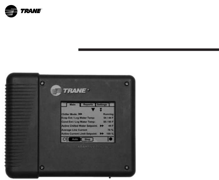
Figure 17. DynaView™ main processor
The DynaView™ (DV) Operator Interface contains the “Main Processor (MP)” and is mounted on the unit control panel front door where it communicates commands to other modules, collecting data, status and diagnostic information from the other modules over the IPC (Inter Processor Communications) link. The Main Processor (MP) software controls water flows by starting pumps and sensing flow inputs, establishes a need to heat or cool, performs pre-lube, performing post-lube, starts the compressor(s), performs water temperature control, establishes limits, and pre-positions the inlet guide-vanes.
The MP contains non-volatile memory both checking for valid set points and retaining them on any power loss. System data from modules (LLID) can be viewed at the DynaView™ operator interface. Such as evaporator and condenser water temperatures, outdoor air temperature, evaporator and condenser water pump control, status and alarm relays, external auto-stop, emergency stop, evaporator and condenser water pressure drops and evaporator and condenser water flow switches.
DynaView™ presents three menu tabs across the top which are labeled “MAIN, REPORTS, and SETTINGS”.
The Main screen provides an overall high level chiller status so the operator can quickly understand the mode of operation of the chiller.
The Chiller Operating Mode will present a top level indication of the chiller mode (Auto, Running, Inhibit, Run Inhibit, etc.) The “additional info” icon will present a subscreen that lists in further detail the subsystem modes. (See Machine Operating Modes.)
Main screen content can be viewed by selecting the up or down arrow icons. The Main screen is the default screen and after an idle time of 30 minutes.
28 |
CVHE-SVU01E-EN |

Operator
Interface
DynaView™ (DV) is the operator interface of the Tracer CH530 control system utilized on the CTV machine. The DynaView™ enclosure is 9.75" wide, 8” high and 1.6” deep. The DynaView™ display is approximately 4” wide by 3” high. Features of the display include a touch screen and long life LED backlight. This device is capable of operating in 0 - 95 percent relative humidity (non-condensing), and is designed and tested with UV considerations consistent with an outdoor application in direct sunlight. The enclosure includes a weather tight connection means for the RS232 service tool connection.
Touch screen key functions are determined completely in the software and change depending upon the subject matter currently being displayed. The user operates the touch sensitive buttons by touching the button of choice. The selected button is darkened to indicate it is the selected choice. The advantage of touch sensitive buttons is that the full range of possible choices as well as the current choice is always in view.
Spin values (up or down) are a graphical user interface model used to allow a continuously variable setpoint, such as leaving water setpoint to be changed. The value changes by touching the increment or decrement arrows.
Action buttons are buttons that appear temporarily and provide the operator with a choice such as Enter or Cancel. The operator indicates his choice by touching the button of choice. The system then takes the appropriate action and the button typically disappears.
DynaView™ consists of various screens, each meant to serve a unique purpose of the machine being served. Tabs are shown row across the top of the display. The user selects a screen of information by touching the appropriate tab. The folder that is selected will be brought to the front so it’s contents are visable
The main body of the screen is used for description text, data, setpoints, or keys (touch sensitive areas) The double up arrows cause a page by page scroll either up or down. The single arrow causes a line by line scroll to occur. At the end of the screen, the appropriate scroll buttons will disappear. Wrap around will not occur.
The bottom of the screen is the persistent area. It is present in all screens and performs the following functions. The left circular area is used to reduce the contrast and viewing angle of the display. The right circular area is used to increase the contrast and viewing angle of the display. The contrast control will be limited to avoid complete “light” or complete “dark”, which would potentially confuse an unfamiliar user to thinking the display was malfunctioning.
CVHE-SVU01E-EN |
29 |
Operator
Interface
The Auto and Stop keys are used to put the unit into the auto or stop modes. Key selection is indicated by being darkened (reverse video).
The Alarms button is to the right of the Stop key. The Alarms button appears only when alarm information is present. The alarm blinks to draw attention to the shutdown diagnostic condition. Blinking is defined as normal versus reverse video. Pressing on the Alarms button takes you to the corresponding screen.
Persistent keys, horizontal at the bottom of the display, are those keys that must be available for operation regardless of the screen currently being displayed. These keys are critical for machine operation. The
Auto and Stop keys will be presented as radio buttons within the persistent key display area. The
selected key will be dark. The chiller will stop when the Stop key is touched, entering the stop sequence. Pressing the “Immediate Stop” button will cause the chiller to stop right away.
The AUTO and STOP, take precedence over the ENTER and CANCEL keys. (While a setting is being changed, AUTO and STOP keys are recognized even if ENTER or CANCEL has not been pressed. Selecting the Auto key will enable the chiller for active cooling ( if no diagnostic is present.)
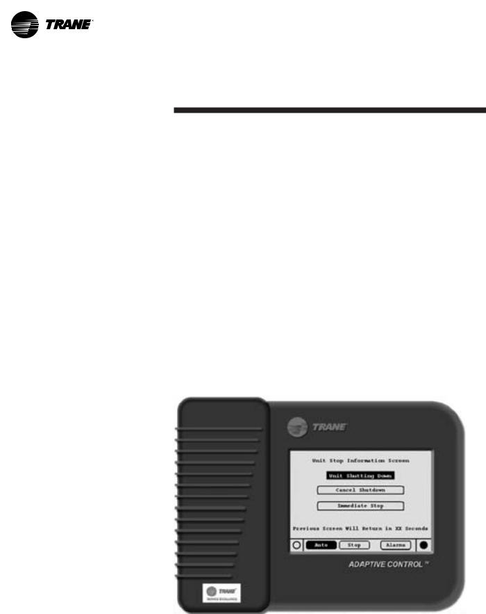
Chiller Stop Prevention/Inhibit Feature
A new chiller “Stop prevention/ inhibit” feature allows a user to prevent an inadvertent chiller stop from the DynaView screen for those chillers which are solely controlled by the CH530.
How It Works
This new feature will be activated after the service tech sets a variable shut down timer in TechView to be greater that 0 seconds and up to 20 seconds (i.e. 0 < Timer ± 20). Then, when the user presses the ‘STOP’ button on the DynaView display and initiates a chiller shutdown, a window will now appear that displays the “Unit Stop Information Screen” as shown below.
TechView service tool is utilized to enable this feature.
30 |
CVHE-SVU01E-EN |
Loading...