


Roof Curbs
Installation Instructions
Roof Curbs
for Performance Climate Changer™ Air Handlers
Sizes 3-120
SAFETY WARNING
Only qualified personnel should install and service the equipment. The installation, starting up, and
servicing of heating, ventilating, and air-conditioning equipment can be hazardous and requires specific
knowledge and training. Improper ly installed, adjusted or alter ed equipment by an unqualified person could
result in death or serious injury. When working on the equipment, observe all precautions in the literature
and on the tags, stickers, and labels that are attached to the equipment.
X-396412040 10
October 2011
CLCH-SVN05A-EN

Warnings, Cautions and Notices
Warnings, Cautions and Notices.
appropriate intervals throughout this manual. Warnings are provided to alert installing contractors
to potential hazards that could result in personal injury or death. Cautions are designed to alert
personnel to hazardous situations that could result in personal injury, while notices indicate a
situation that could result in equipment or property-damage-only accidents.
Y our personal safety and the proper operation of this machine depend upon the strict observance
of these precautions.
ATTENTION:
this literature. Read these carefully.
WARNING:
result in death or serious injury.
CAUTION:
result in minor or moderate injury . It could also be used to aler t against unsafe practices.
NOTICE:
accidents.
WARNING
Warnings, Cauti ons and Notice s appe ar a t app rop riat e s ection s th roug hout
Indicates a potentially hazardous situation which, if not avoided, could
Indicates a potentially hazardous situation which, if not avoided, could
Indicates a situation that could result in equipment or property-damage-only
Note that warnings, cautions and notices appear at
Personal Protective Equipment (PPE) Required!
Installing/servicing this unit could result in exposure to electrical, mechanical and chemical
hazards.
• Before installing/servicing this unit, technicians MUST put on all Personal Protective
Equipment (PPE) r ecomm ended f or the work being under taken. ALWAYS ref e r t o a ppr o priate
MSDS and OSHA guidelines for proper PPE.
• When working with or around hazardous chemicals, ALWAYS refer to appropriate MSDS and
OSHA guidelines for information on allowable personal exposure levels, proper respiratory
protection and handling recommendations.
• If there is a r isk of arc or flash, technicians MUS T put on all Personal Protective Equipment (PPE)
in accordance with NFPA70E or other country-specific requirements for arc/flash protection
PRIOR to servicing the unit.
Failure to follow recommendations could result in death or serious injury.
Introduction
Overview of Manual
Performance Climate Changer™ air handlers may be mounted on the roof with a roof curb or pier
mount. This manual includes the assembly instructions for Performance air handler roof curb s.
Before proceeding with the installation, refer to the unit submittal drawings and unit tagging for
correct placement of air handler sections. Failure to review the submittal drawings could result in
performance or assembly problems. If there are any discrepancies, contact your local Trane sales
engineer before proceeding. Carefully review the procedures discussed in this manual to minimize
installation and startup difficulties.
2 CLCH-SVN05A-EN
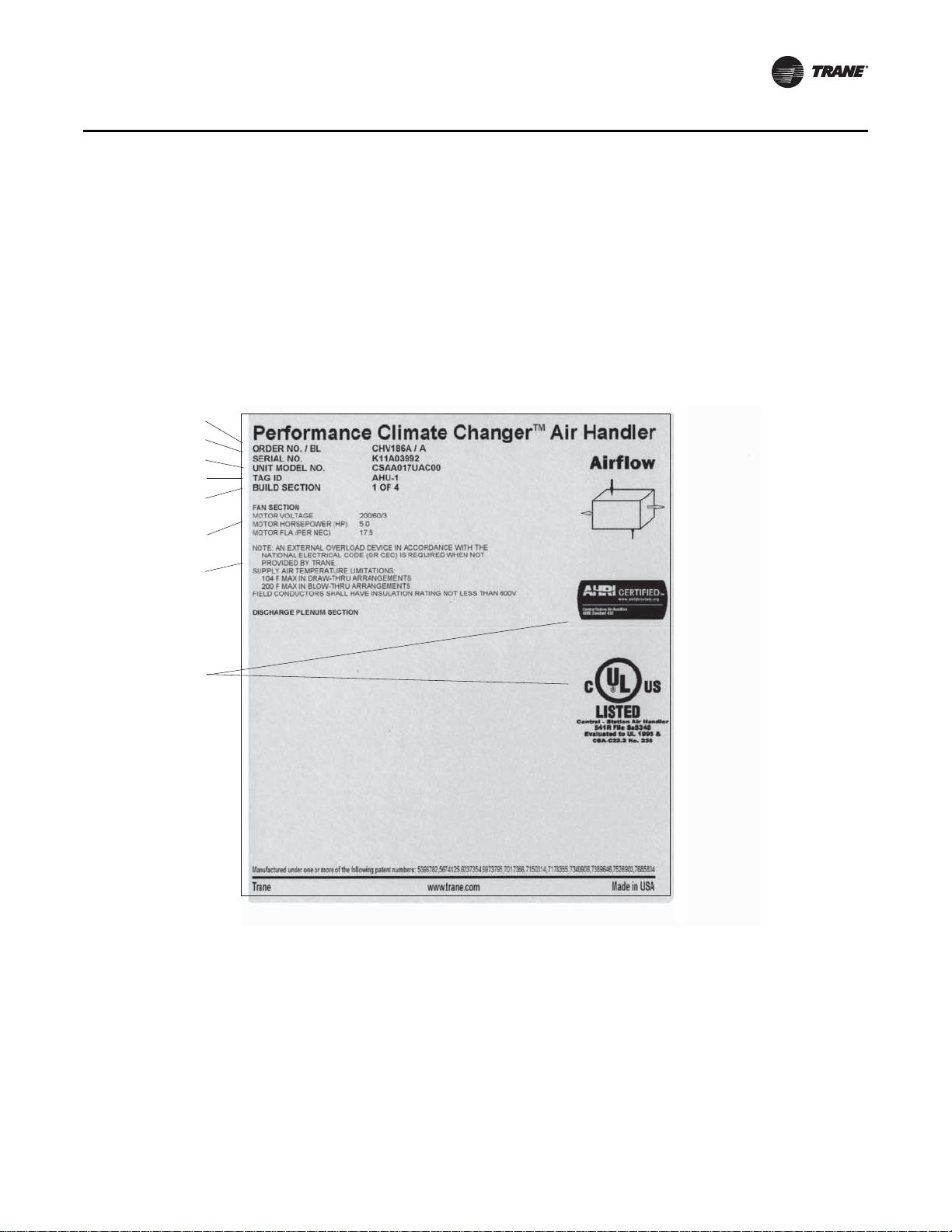
Nameplate
Agency listings and/or
agency certifications
Trane order number
Unit level serial number
Service model number
Unit tagging
Section location
Functional section type
Notes and additional
section information
Each P erformance air handler section shipped includes at least one nameplate/label (see Figure 1),
which identifies the type of section and functional components, cust omer tagging information, the
unit serial number, the unit order number, the bu ild se ction po siti on for in stalla tion , and th e uni t
model number. Refer to this information when ordering replacement parts or requesting service.
Note: The unit serial number and order number is required when ordering parts or requesting
service for a Trane air handler.
Figure 1. Performance air handler section nameplate
General Information
General Information
CLCH-SVN05A-EN 3
As-built submittals show the intended layout of the various air handler sections to meet job site
requirements. Installation information (unit dimensions, clearances, weights, curb location and
roof opening dimensions and locations) may vary with special equipment and applications. For
exact information, always refer to the specific unit submittals, which can be obtained from your
local Trane sales office.
Roof curbs for Performance air handlers are shipped “knocked down” for assembly at the job site.
General Information
Preparing the Unit Site
Ensure the installation site can support the total weight of the air-handling unit, includi ng
accessories and the roof curb. For approximate air handler section weights, refer to Performance
Climate Changer™Air Handler IOM, CLCH-SVX07C-EN. Units with special options or arrangements
will differ in dimensions, clear ances, weights and roof opening dimension s and locations. Always
refer to unit submittals before marking off the dimensions of the unit roof curb, pipe cabinet curb
(if pipe cabinet is ordered), and roof openings. For roof curbs supplied by T rane, approximate roof
curb weights are in Table 1.
Note: To calculate the total curb weight, find the unit length, multiply by the factor supplied in
Table 1 for the applicable roof curb height, and add the curb end weight for the applicable
roof curb height.
Table 1. Curb weights
Curb
height Unit Size 3 4 6 8 10 12 14 17 21 25
14-inch
18-inch
22-inch
26-inch
30-inch
36-inch
Curb
height
14-inch
18-inch
22-inch
26-inch
30-inch
36-inch
Note: Example: Size 21 Performance air handler with airfoil damper mixing section, small coil section, medium access section, medium coil section, small
blank section, VFD control section, and fan section (down discharge) total unit length is 156.75 inches. Total roof curb weight for the 18-inch curb
would be 502.80 lbs (156.75 x 1.05 = 164.5875 lbs + 338.21 = 502.7975 lbs.)
Curb end and duct
support weight
Curb side weight Take total length in inches, multiply by 0.56 pounds, and add to the ab ove curb end & duct support weight.
Curb end and duct
support weight
Curb side weight Take total length in inches, multiply by 1.05 pounds, and ad d to the abov e curb end & duct support weight.
Curb end and duct
support weight
Curb side weight Take total length in inches, multiply by 1.22 pounds, and add to the ab ove curb end & duct support weight.
Curb end and duct
support weight
Curb side weight Take total length in inches, multiply by 2.00 pounds, and ad d to the abov e curb end & duct support weight.
Curb end and duct
support weight
Curb side weight Take total length in inches, multiply by 2.25 pounds, and add to the ab ove curb end & duct support weight.
Curb end and duct
support weight
Curb side weight Take total length in inches, multiply by 2.63 pounds, and ad d to the abov e curb end & duct support weight.
117.23 155.82 155.82 175.88 209.84 225.27 242.25 242.25 266.94 266.94
148.76 197.59 197.59 222.98 265.95 285.48 306.96 306.96 338.21 338.21
171.54 227.14 227.14 256.05 304.98 327.22 351.68 351.68 387.26 387.26
215.31 286.02 286.02 322.78 385.00 413.28 444.39 444.39 489.64 489.64
240.72 319.23 319.23 360.06 429.15 460.56 495.11 495.11 545.36 545.36
278.82 369.05 369.05 415.98 495.38 531.48 571.18 571.18 628.93 628.93
Unit Size 30 35 40 50 57 66 80 100 120
Curb end and duct
support weight
Curb side weight Take total length in inches, multiply by 0.56 pounds, and add to the abo ve curb e nd & duct sup port weight.
Curb end and duct
support weight
Curb side weight Take total length in inches, multiply by 1.05 pounds, and ad d to the abov e curb end & duct support weight.
Curb end and duct
support weight
Curb side weight Take total length in inches, multiply by 1.22 pounds, and add to the abo ve curb e nd & duct sup port weight.
Curb end and duct
support weight
Curb side weight Take total length in inches, multiply by 2.00 pounds, and ad d to the abov e curb end & duct support weight.
Curb end and duct
support weight
Curb side weight Take total length in inches, multiply by 2.25 pounds, and add to the abo ve curb e nd & duct sup port weight.
Curb end and duct
support weight
Curb side weight Take total length in inches, multiply by 2.63 pounds, and ad d to the abov e curb end & duct support weight.
308.62 328.68 367.27 407.39 407.39 453.70 453.70 496.91 581.80
390.95 416.34 465.17 515.95 515.95 574.54 574.54 629.23 736.65
447.31 476.22 531.82 589.64 589.64 656.36 656.36 718.63 840.95
566.00 602.77 673.47 747.00 747.00 831.85 831.85 911.03 1066.58
630.15 670.98 749.50 831.15 831.15 925.37 925.37 1013.31 1186.04
726.38 773.30 863.54 957.38 957.38 1065.66 1065.66 1166.73 1365.24
4 CLCH-SVN05A-EN
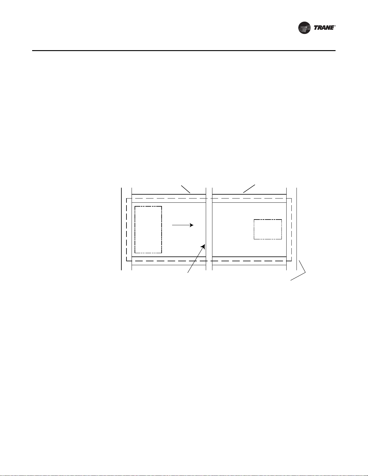
Installation Considerations
Discharge
Intake
Airflow
Auxillary support
loaded under curbs
Roof mounting curb
inside edge
Main roof support member
capable of supporting unit
weight
Main roof support member
or auxillary support located
under center of unit or under
section joints
• Isolation rails should not be installed on top of Trane roof curbs. If isolation rails or isolation
curbs are required, the entire curb system should be supplied by a specialty curb company.
Note: For proper operation, the unit must be supported around the entire unit base perimeter.
The roof curb must be supported al ong its entire perimeter . The curb may be set paralle l or at right
angles to roof support members. If at right angles to the supp ort members, there must be adequate
supporting roof cross members between the ends (in the direction of airflow). Be sure the cross
members do not interfere with the connection of supply and return ducts to the uni t. See Figure 2
for details.
Figure 2. Unit set perpendicular to roof curb members
Installation Considerations
• When mounting the unit on its roof curb, make sure that the gasketing between the roof curb
and unit base provides an airtight seal.
Note: When pulling shipping split sections together , the field-supplied gasket material may bunch
up between bases. Make certain this does not prevent tight contact between shipping
CLCH-SVN05A-EN 5
sections.
Installation Considerations
Piers
4 ft
3.0 in. - sizes 3-50
4.0 in. - sizes 57-120
6.0 in. - sizes 3-120
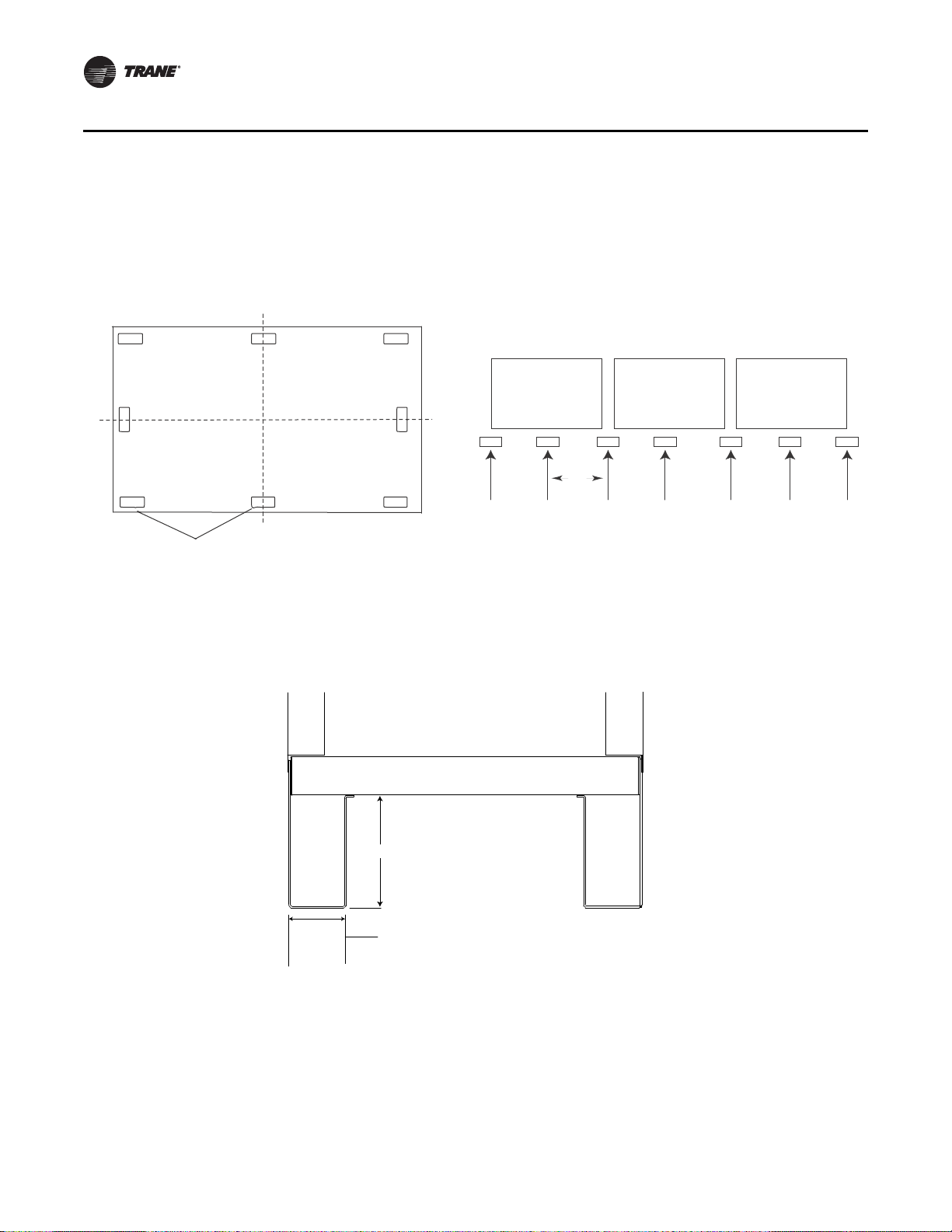
• If a unit is pier-mounted, at a minimum, locate one pier at each corner directly underneath any
shipping split (ensure full support under eac h side), and then every four feet at equally spaced
intervals around the perimeter of the unit. Both the unit and the pipe cabinet should be
supported by their base channel around the entire perimeter (see Figure 3 and Figure 4).
Figure 3. Pier locations (typical) Figure 4. Side view with shipping splits
Note: Piers beneath shipping splits must be structurally sound to support the weight of the unit.
See Figure 5 for typical cross section for pier- or slab-mounted base.
Figure 5. Typical cross section for pier-mounted or slab-mounted base.
• For new building construction, the roof curb may be installed as soon as the roof support
members are in place. Trane recommends that the roof curb be placed directly on the roof
support members and welded into place. If the curb is mounted on the roof deck, additional
support is necessary directly below the curb flanges to minimize vibration.
6 CLCH-SVN05A-EN
 Loading...