


 Loading...
Installation, Operation,
and Maintenance
Stealth™ Air-Cooled Chiller Model RTAE
150 to 300 Nominal Tons
 SAFETY WARNING
Only qualified personnel should install and service the equipment. The installation, starting up, and servicing of heating, ventilating, and airconditioning equipment can be hazardous and requires specific knowledge and training. Improperly installed, adjusted or altered equipment by an unqualified person could result in death or serious injury. When working on the equipment, observe all precautions in the literature and on the tags, stickers, and labels that are attached to the equipment.
October 2014 |
RTAE-SVX001B-EN |
Warnings, Cautions and Notices
Warnings, Cautions and Notices. Note that warnings, cautions and notices appear at appropriate intervals throughout this manual. Warnings are provided to alert installing contractors to potential hazards that could result in death or personal injury. Cautions are designed to alert personnel to hazardous situations that could result in personal injury, while notices indicate a situation that could result in equipment or property-damage-only accidents.
Your personal safety and the proper operation of this machine depend upon the strict observance of these precautions.
Read this manual thoroughly before operating or servicing this unit.
ATTENTION: Warnings, Cautions and Notices appear at appropriate sections throughout this literature. Read these carefully:
 WARNING
 CAUTIONs
NOTICE:
Indicates a potentially hazardous situation which, if not avoided, could result in death or serious injury.
Indicates a potentially hazardous situation which, if not avoided, could result in minor or moderate injury. It could also be used to alert against unsafe practices.
Indicates a situation that could result in equipment or property-damage only
Important
Environmental Concerns!
Scientific research has shown that certain man-made chemicals can affect the earth’s naturally occurring stratospheric ozone layer when released to the atmosphere. In particular, several of the identified chemicals that may affect the ozone layer are refrigerants that contain Chlorine, Fluorine and Carbon (CFCs) and those containing Hydrogen, Chlorine, Fluorine and Carbon (HCFCs). Not all refrigerants containing these compounds have the same potential impact to the environment.Trane advocates the responsible handling of all refrigerants-including industry replacements for CFCs such as HCFCs and HFCs.
Responsible Refrigerant Practices!
Trane believes that responsible refrigerant practices are important to the environment, our customers, and the air conditioning industry. All technicians who handle refrigerants must be certified.The Federal Clean Air Act (Section 608) sets forth the requirements for handling, reclaiming, recovering and recycling of certain refrigerants and the equipment that is used in these service procedures. In addition, some states or municipalities may have additional requirements that
must also be adhered to for responsible management of refrigerants. Know the applicable laws and follow them.
 WARNING
Refrigerant under High Pressure!
System contains oil and refrigerant under high pressure. Recover refrigerant to relieve pressure before opening the system. See unit nameplate for refrigerant type. Do not use non-approved refrigerants, refrigerant substitutes, or refrigerant additives. Failure to recover refrigerant to relieve pressure or the use of nonapproved refrigerants, refrigerant substitutes, or refrigerant additives could result in an explosion which could result in death or serious injury or equipment damage.
 WARNING
Personal Protective Equipment (PPE)
Required!
Installing/servicing this unit could result in exposure to electrical, mechanical and chemical hazards.
•Before installing/servicing this unit, technicians MUST put on all PPE required for the work being undertaken (Examples; cut resistant gloves/sleeves, butyl gloves, safety glasses, hard hat/bump cap, fall protection, electrical PPE and arc flash clothing). ALWAYS refer to appropriate Material Safety Data Sheets (MSDS)/Safety Data Sheets (SDS) and OSHA guidelines for proper PPE.
•When working with or around hazardous chemicals, ALWAYS refer to the appropriate MSDS/SDS and OSHA/GHS (Global Harmonized System of Classification and Labelling of Chemicals) guidelines for information on allowable personal exposure levels, proper respiratory protection and handling instructions.
•If there is a risk of energized electrical contact, arc, or flash, technicians MUST put on all PPE in accordance
with OSHA, NFPA 70E, or other country-specific requirements for arc flash protection, PRIOR to servicing the unit. NEVER PERFORM ANY SWITCHING, DISCONNECTING, OR VOLTAGE TESTING WITHOUT PROPER ELECTRICAL PPE AND ARC FLASH CLOTHING. ENSURE ELECTRICAL METERS AND EQUIPMENT ARE PROPERLY RATED FOR INTENDED VOLTAGE.
Failure to follow instructions could result in death or serious injury.
© 2014Trane All rights reserved |
RTAE-SVX001B-EN |

Warnings, Cautions and Notices
 WARNING
Proper Field Wiring and Grounding
Required!
All field wiring MUST be performed by qualified personnel. Improperly installed and grounded field wiring poses FIRE and ELECTROCUTION hazards. To avoid these hazards, you MUST follow requirements for field wiring installation and grounding as described in NEC and your local/state electrical codes. Failure to follow code could result in death or serious injury.
Factory Warranty Information
Compliance with the following is required to preserve the factory warranty:
All Unit Installations
Startup MUST be performed byTrane, or an authorized agent ofTrane, to VALIDATE this WARRANTY. Contractor must provide a two-week startup notification toTrane (or an agent ofTrane specifically authorized to perform startup).
Copyright
This document and the information in it are the property of Trane, and may not be used or reproduced in whole or in part without written permission.Trane reserves the right to revise this publication at any time, and to make changes to its content without obligation to notify any person of such revision or change.
Trademarks
All trademarks referenced in this document are the trademarks of their respective owners.
Revision History
RTAE-SVX001B-EN (29 Oct 2014)
•Added transformer option.
•Added harmonic filter option.
•Added 150T and 165T single circuit units.
•Added extreme low ambient option.
•Added seismic isolation option.
•Added CE/PED option.
•Updated unit weights and isolator information.
•Updated drive cooling fluid volumes.
•Modified oil sump check procedure.
RTAE-SVX001A-EN (24 Sep 2013)
New release.
RTAE-SVX001B-EN |
3 |

Table of Contents |
|
Warnings, Cautions and Notices . . . . . . . . . . |
2 |
Factory Warranty Information . . . . . . . . . . . |
3 |
Copyright . . . . . . . . . . . . . . . . . . . . . . . . . . . . . |
3 |
Trademarks . . . . . . . . . . . . . . . . . . . . . . . . . . . |
3 |
Revision History . . . . . . . . . . . . . . . . . . . . . . . |
3 |
Model Number Description . . . . . . . . . . . . . . . |
6 |
Outdoor Unit Nameplate . . . . . . . . . . . . . . . |
6 |
Compressor Nameplate . . . . . . . . . . . . . . . . |
6 |
Model Number Descriptions . . . . . . . . . . . . . . |
7 |
Unit Model Number . . . . . . . . . . . . . . . . . . . . |
7 |
Compressor Model Number . . . . . . . . . . . . |
8 |
Compressor Serial Number . . . . . . . . . . . . . |
8 |
General Information . . . . . . . . . . . . . . . . . . . . . |
9 |
Unit Description . . . . . . . . . . . . . . . . . . . . . . . |
9 |
Accessory/Option Information . . . . . . . . . . . |
9 |
General Data . . . . . . . . . . . . . . . . . . . . . . . . . . . |
10 |
Drive Cooling System . . . . . . . . . . . . . . . . . |
11 |
Pre-Installation . . . . . . . . . . . . . . . . . . . . . . . . . |
12 |
Unit Inspection . . . . . . . . . . . . . . . . . . . . . |
12 |
Inspection . . . . . . . . . . . . . . . . . . . . . . . . . |
12 |
Storage . . . . . . . . . . . . . . . . . . . . . . . . . . . |
12 |
Installation Requirements . . . . . . . . . . . . . . |
13 |
Dimensions and Weights . . . . . . . . . . . . . . . . |
14 |
Weights . . . . . . . . . . . . . . . . . . . . . . . . . . . . . |
14 |
Unit Dimensions . . . . . . . . . . . . . . . . . . . . . . |
14 |
Service Clearances . . . . . . . . . . . . . . . . . . . . |
14 |
Installation Mechanical . . . . . . . . . . . . . . . . . . |
15 |
Location Requirements . . . . . . . . . . . . . . . . |
15 |
Sound Considerations . . . . . . . . . . . . . . . |
15 |
Foundation . . . . . . . . . . . . . . . . . . . . . . . . |
15 |
Clearances . . . . . . . . . . . . . . . . . . . . . . . . . |
15 |
Center of Gravity . . . . . . . . . . . . . . . . . . . . . |
20 |
Isolation and Sound Emission . . . . . . . . . . |
20 |
Unit Isolation and Leveling . . . . . . . . . . . |
20 |
Compressor Shipping Bolt Removal . . . . |
23 |
Units with InvisiSound™ Ultimate Option |
|
(Model Number Digit 12 = 3) . . . . . . . . . . |
23 |
Drainage . . . . . . . . . . . . . . . . . . . . . . . . . . . . |
23 |
Evaporator Piping Components . . . . . . . |
25 |
Pressure Relief Valves . . . . . . . . . . . . . . . . . .26
Evaporator Waterside Pressure Drop
Curves . . . . . . . . . . . . . . . . . . . . . . . . . . . . . . .27
Freeze Protection . . . . . . . . . . . . . . . . . . . . . .29
Low Evaporator Refrigerant Cutout,
Glycol Requirements . . . . . . . . . . . . . . . . . . .30
Installation Electrical . . . . . . . . . . . . . . . . . . . . .31
General Recommendations . . . . . . . . . . . . .31
Adaptive Frequency™ Drive (AFD3)
Capacitor Discharge . . . . . . . . . . . . . . . . . .32
Units with Nitrogen Charge Option . . . . .32
Installer-Supplied Components . . . . . . . . . .32
Power Supply Wiring . . . . . . . . . . . . . . . . .33
Control Power Supply . . . . . . . . . . . . . . . .34
Service Power Connection . . . . . . . . . . . .34
Heater Power Supply . . . . . . . . . . . . . . . . .34
Interconnecting Wiring . . . . . . . . . . . . . . . . .35
Chilled Water Pump Control . . . . . . . . . . .35
Programmable Relays . . . . . . . . . . . . . . . . . .35
Relay Assignments Using Tracer™ TU . . .36
Low Voltage Wiring . . . . . . . . . . . . . . . . . . . .36
Emergency Stop . . . . . . . . . . . . . . . . . . . . .36
External Auto/Stop . . . . . . . . . . . . . . . . . . .36
External Circuit Lockout –
Circuit #1 and #2 . . . . . . . . . . . . . . . . . . . . .36
Ice Building Option . . . . . . . . . . . . . . . . . .37
External Chilled Water Setpoint (ECWS)
Option . . . . . . . . . . . . . . . . . . . . . . . . . . . . .37
External Demand Limit Setpoint (EDLS)
Option . . . . . . . . . . . . . . . . . . . . . . . . . . . . .37
Chilled Water Reset (CWR) . . . . . . . . . . . .38
Transformer Power Rating . . . . . . . . . . . . . .39
Communications Interface . . . . . . . . . . . . . .39
LonTalk Interface (LCI-C) . . . . . . . . . . . . . .39
BACnet Interface (BCI-C) . . . . . . . . . . . . . .39
Modbus Remote Terminal Unit Interface .39
Operating Principals . . . . . . . . . . . . . . . . . . . . .40
Refrigeration Circuits . . . . . . . . . . . . . . . . . .40
Refrigeration Cycle . . . . . . . . . . . . . . . . . . . .40
Refrigerant R-134a . . . . . . . . . . . . . . . . . . . . .40
4 |
RTAE-SVX001B-EN |

Compressor and Lube Oil System . |
. . . . . 40 |
Condenser and Fans . . . . . . . . . . . . . |
. . . . . 40 |
Evaporator . . . . . . . . . . . . . . . . . . . . . . |
. . . . . 41 |
Drive Cooling System . . . . . . . . . . . . |
. . . . . 41 |
Controls . . . . . . . . . . . . . . . . . . . . . . . . . . |
. . . . . 42 |
UC800 Specifications . . . . . . . . . . . . . |
. . . . . 42 |
Wiring and Port Descriptions . . . . |
. . . . . 42 |
Communication Interfaces . . . . . . . |
. . . . . 43 |
Rotary Switches . . . . . . . . . . . . . . . |
. . . . . 43 |
LED Description and Operation . . . |
. . . . . 43 |
Tracer AdaptiView TD7 Display . . . . |
. . . . . 43 |
Operator Interface . . . . . . . . . . . . . |
. . . . . 43 |
Main Display Area/Home Screen . |
. . . . . 44 |
Viewing Chiller Operating Modes |
. . . . . 44 |
Alarms . . . . . . . . . . . . . . . . . . . . . . |
. . . . . 46 |
Reports . . . . . . . . . . . . . . . . . . . . . . |
. . . . . 47 |
Equipment Settings . . . . . . . . . . . . |
. . . . . 49 |
Display Settings . . . . . . . . . . . . . . . |
. . . . . 51 |
Viewing the Settings Screen . . . . |
. . . . . 51 |
Cleaning the Display . . . . . . . . . . . |
. . . . . 52 |
Security Settings . . . . . . . . . . . . . . |
. . . . . 52 |
Disabling/Enabling Security . . . . . |
. . . . . 52 |
InvisiSound Ultimate - Noise Reduction |
|
Mode . . . . . . . . . . . . . . . . . . . . . . . . |
. . . . . 54 |
Tracer™ TU . . . . . . . . . . . . . . . . . . . . . |
. . . . . 55 |
Pre-Start . . . . . . . . . . . . . . . . . . . . . . . . . . |
. . . . . 56 |
Start-Up and Shutdown . . . . . . . . . . . . |
. . . . . 57 |
Unit Start-Up . . . . . . . . . . . . . . . . . . . . |
. . . . . 57 |
Temporary Shutdown And Restart . |
. . . . . 57 |
Extended Shutdown Procedure . . . . |
. . . . . 57 |
Seasonal Unit Start-Up Procedure . |
. . . . . 58 |
System Restart After Extended Shutdown 58 |
|
Sequence of Operation . . . . . . . . . . . |
. . . . . 59 |
Software Operation Overview . . . . |
. . . . . 59 |
Timelines . . . . . . . . . . . . . . . . . . . . . |
. . . . . 59 |
Power Up Diagram . . . . . . . . . . . . . |
. . . . . 60 |
Power Up to Starting . . . . . . . . . . . |
. . . . . 61 |
Stopped to Starting . . . . . . . . . . . . |
. . . . . 62 |
Running (Lead Compressor/Circuit Start |
|
and Run) . . . . . . . . . . . . . . . . . . . . . |
. . . . . 63 |
Running (Lag Compressor/Circuit
Start and Run) . . . . . . . . . . . . . . . . . . . . . .63
Satisfied Setpoint . . . . . . . . . . . . . . . . . . . .64
Normal Shutdown to Stopped or
Run Inhibit . . . . . . . . . . . . . . . . . . . . . . . . .65
Immediate Shutdown to Stopped or
Run Inhibit . . . . . . . . . . . . . . . . . . . . . . . . .65
Ice Making (Running to Ice Making to Running) . . . . . . . . . . . . . . . . . . . . . . . . . . .66
Ice Making (Auto to Ice Making to Ice Making Complete) . . . . . . . . . . . . . . . . . . .67
Maintenance . . . . . . . . . . . . . . . . . . . . . . . . . . . .68
Recommended Maintenance . . . . . . . . . . . .69
Weekly . . . . . . . . . . . . . . . . . . . . . . . . . . . . .69
Monthly . . . . . . . . . . . . . . . . . . . . . . . . . . . .69
Annual . . . . . . . . . . . . . . . . . . . . . . . . . . . . .69
Refrigerant and Oil Charge Management .69
Lubrication System . . . . . . . . . . . . . . . . . . . .69
Oil Sump Level Check . . . . . . . . . . . . . . . .69
Drive Cooling System . . . . . . . . . . . . . . . . . .71
Service Intervals . . . . . . . . . . . . . . . . . . . . .71
Unit Diagnostics . . . . . . . . . . . . . . . . . . . . .71
pH Test . . . . . . . . . . . . . . . . . . . . . . . . . . . .71
Pressure Relief Cap . . . . . . . . . . . . . . . . . .71
Drive Cooling Expansion Tank . . . . . . . . .71
Condenser Coils — Cleaning and
Inspection . . . . . . . . . . . . . . . . . . . . . . . . . . . .72
Coil Cleaning and Inspection Interval . . . .72
Cleaning Air Side of RTAE Coils . . . . . . . .72
Cleaning Coated Coils . . . . . . . . . . . . . . . .72
Coil Corrosion Protection Inspection . . . .72
Reinstallation of Compressor Shipping
Bolts . . . . . . . . . . . . . . . . . . . . . . . . . . . . . . . . .72
Servicing Chiller Roof . . . . . . . . . . . . . . . .72
Diagnostics . . . . . . . . . . . . . . . . . . . . . . . . . . . . .73
AFD Diagnostics . . . . . . . . . . . . . . . . . . . . . . .73
Main Processor Diagnostics . . . . . . . . . . . . .76
Communication Diagnostics . . . . . . . . . . . .85
Operator Display Diagnostics and
Messages . . . . . . . . . . . . . . . . . . . . . . . . . . . .88
Unit Wiring . . . . . . . . . . . . . . . . . . . . . . . . . . . . .89
Log and Check Sheet . . . . . . . . . . . . . . . . . . . .90
RTAE-SVX001B-EN |
5 |

Model Number Description
Nameplates
The Stealth™ outdoor unit nameplates are applied to the exterior of the Control Panel. A compressor nameplate is located on each compressor. When the unit arrives, compare all nameplate data with ordering, submittal, and shipping information.
Outdoor Unit Nameplate
See Figure 1 for a typical unit nameplate.The outdoor unit nameplate provides the following information:
•Unit model and size description.
•Unit serial number.
•Identifies unit electrical requirements.
•Lists correct operating charges of R-134a and refrigerant oil (Trane OIL00311).
•Lists unit test pressures.
•Identifies installation, operation and maintenance and service data literature.
•Lists drawing numbers for unit wiring diagrams.
of typical unit model number and the coding system for each.
Each position, or group of positions, in the model number is used to represent a feature. For example, in the first table, position 08 of the unit model number, Unit Voltage, contains the number “4”.A 4 in this position means that the unit voltage is 460/60/3.
Unit Model Number. An example of a typical unit model number (M/N) is:
RTAE 200F UA01 AA1F N1X1 A1A0 0CB0 X02X AA03 000
Model number digits are selected and assigned in accordance with the definitions as listed in “Unit Model Number,” p. 7.
Compressor Nameplate
The compressor nameplate provides the following information:
•Compressor model number. See “Compressor Model Number,” p. 8.
•Compressor serial number. See “Compressor Serial Number,” p. 8.
Model Number Coding System
The model numbers for the unit and the compressor are composed of numbers and letters that represent features of the equipment. Shown in the following table is a sample
•Compressor electrical characteristics.
•Utilization range.
•Recommended refrigerant.
Figure 1. |
Typical unit nameplate |
6 |
RTAE-SVX001B-EN |

Model Number Descriptions
Unit Model Number
Digits 1,2 — Unit Model
RT = Rotary Chiller
Digits 3— Unit Type
A = Air-cooled
Digits 4 — Development
Sequence
E = Development Sequence
Digits 5-7 — Nominal Capacity
149 = 150 NominalTons Single Circuit
164 = 165 NominalTons Single Circuit
150 = 150 NominalTons
165 = 165 NominalTons
180 = 180 NominalTons
200 = 200 NominalTons
225 = 225 NominalTons
250 = 250 NominalTons
275 = 275 NominalTons
300 = 300 NominalTons
Digit 8— Unit Voltage
A |
= |
200/60/3 |
B |
= |
230/60/3 |
C |
= |
380/50/3 |
D |
= |
380/60/3 |
E |
= |
400/50/3 |
F |
= |
460/60/3 |
G |
= |
575/60/3 |
H |
= |
400/60/3 |
Digit 9 — Manufacturing
Location
U = Trane Commercial Systems,
Pueblo, CO USA
Digits 10, 11— Design Sequence
** = Factory assigned
Digit 12 — Unit Sound Package
1= InvisiSound™ Standard Unit
2= InvisiSound Superior
(Line Wraps, Reduced Fan
Speed)
3= InvisiSound Ultimate
(Compressor Sound Attenuation, Line Wraps, Reduced Fan Speed)
Digit 13 — Agency Listing
0 |
= |
No Agency Listing |
A |
= |
UL/CUL Listing |
C |
= |
CE European Safety Standard |
Digit 14 — Pressure Vessel Code
A |
= |
ASME Pressure Vessel Code |
D |
= |
Australia Pressure Vessel Code |
C= CRN or Canada Equivalent Pressure Vessel Code
L = Chinese Pressure Vessel Code
P= PED European Pressure Vessel
Code
Digit 15 — Factory Charge
1= Refrigerant Charge HFC-134a
2= Nitrogen Charge
Digit 16 — Evaporator
Application
F = Standard Cooling
(40 to 68°F/5.5 to 20°C)
G= LowTemp Process (<40°F LeavingTemp)
C= Ice-making (20 to 68°F/-7 to 20°C) w/ Hardwired Interface
Digit 17 — Evaporator
Configuration
N |
= |
2 Pass Evaporator |
P |
= |
3 Pass Evaporator |
Digit 18 — Evaporator Fluid
Type
1 = Water
2= Calcium Chloride
3= Ethylene Glycol
4= Propylene Glycol
5= Methanol
Digit 19 — Water Connection
X |
= |
Grooved Pipe |
F |
= |
Grooved Pipe + Flange |
Digit 20 — Flow Switch
1= Factory Installed - Other Fluid (15 cm/s)
2= Factory Installed - Water 2 (35 cm/s)
3= Factory Installed - Water 3 (45 cm/s)
Digit 21 — Insulation
A= Factory Insulation - All Cold Parts 0.75”
B= Evaporator-Only Insulation - High Humidity/Low EvapTemp 1.25”
Digit 22 — Unit Application
1 |
= |
Standard Ambient |
|
|
(32 to 105°F/0 to 40.6°C) |
2 |
= |
Low Ambient |
|
|
(0 to 105°F/-17.7 to 40.6°C) |
3 |
= |
Extreme Low Ambient |
|
|
(-20 to 105°F/-28.9 to 40.6°C) |
4 |
= |
High Ambient |
|
|
(32 to 125°F/0 to 52°C) |
5 |
= |
Wide Ambient |
|
|
(0 to 125°F/-17.7 to 52°C) |
Digit 23 — Condenser Fin Options
A = Aluminum Fins with Slits
D= CompleteCoat™ Epoxy Coated Fins
Digits 24, 25 — Not Used
Digit 26 — Power Line
Connection Type
A = Terminal Block
C= Circuit Breaker
D= Circuit Breaker w/ High Fault Rated Control Panel
Digit 27 — Short Circuit Current
Rating
A= Default A Short Circuit Rating
B= High A Short Circuit Rating
Digit 28 — Transformer
0 |
= |
NoTransformer |
1 |
= |
Factory InstalledTransformer |
Digit 29 — Line Voltage
Harmonic Mitigation
X |
= |
Line Reactors (~30%TDD) |
1 |
= |
Filter circuit (IEEE519 Compliant) |
Digit 30 — Electrical
Accessories
0 = No Convenience Outlet
C= 15A 115V convenience Outlet (Type B)
Digit 31 — Remote
Communication Options
0= No Remote Digital Communication
1= LonTalk® Interface LCI-C (Tracer™ Compatible)
2= BACnet® MS/TP Interface (Tracer compatible)
3= ModBus™ Interface
Digit 32 — Hard Wire
Communication
X = None
A= Hard Wired Bundle - All
B= Remote Leaving WaterTemp Setpoint
C= Remote Leaving temp and Demand Limit Setpoints
D= Programmable Relay
E= Programmable Relay and Leaving Water and Demand
Limit
Setpoint
F= Percent Capacity
G= Percent Capacity and Leaving Water and Demand Limit
Setpoint
H= Percent Capacity and Programmable Relay
Digit 33 — Not Used
RTAE-SVX001B-EN |
7 |

Model Number Descriptions
Digit 34 — Structural Options
A= Standard Unit Structure
B= Seismic to International Building Code (IBC)
C= California Office of Statewide Health Planning and Development (OSHPD) Certification
D= Wind Load for Florida Hurricane 175 MPH
E= Seismic (IBC) and Wind Load
F= OSHPD and Wind Load
Digit 35 — Appearance Options
0 |
= |
No Appearance Options |
A |
= |
Architectural Louvered Panels |
Digit 36 — Unit Isolation
0= No Isolation
1= Elastomeric Isolators
3 = Seismic Rated Isopads
Digit 37 — Not Used
0 = Not Used
Digit 38 — Not Used
0 = Not Used
Digit 39 — Special
0 |
= |
None |
S |
= |
Special |
Compressor Model
Number
Digits 1-4 — Compressor Type
CHHS= Positive displacement, helical rotary (twin screw) hermetic compressor
Digit 5 — Frame Size
R= R Frame: 70 - 100 tons
S= S Frame: 112 - 165 tons
Digit 6— Motor Length
B= 145 mm
C= 170 mm
E= 165 mm
F= 190 mm
Digit 7 — Motor Winding
Characteristics
*= Factory assigned
Digit 8 — Volume Ratio
B = High Volume Ratio
Digit 9 — Refrigerant
1 = R-134a
Digits 10-11— Design Sequence
** = Factory assigned
Compressor Serial
Number
Digits 1-2 —Year
YY= Last two digits of year of manufacture
Digit 3— Week
WW= Week of build, from 00 to 52
Digit 5 — Day
1 |
= |
Monday |
2 |
= |
Tuesday |
3 |
= |
Wednesday |
4 |
= |
Thursday |
5 |
= |
Friday |
6 |
= |
Saturday |
7 |
= |
sunday |
Digits 6-8 — Coded Time Stamp
TTT = Used to ensure uniqueness of serial number
Digit 9 — Assembly Line
Assembly line compressor was built on. Varies with facility
Digit 10— Build Location
A = Monterrey
8 |
RTAE-SVX001B-EN |
General Information
Unit Description
The 150-300 ton Stealth™ units are helical-rotary type, aircooled liquid chillers designed for installation outdoors. The compressor circuits are completely assembled, hermetic packages that are factory-piped, wired, leaktested, dehydrated, and tested for proper control operation before shipment.
Chilled water inlet and outlet openings are covered for shipment.The Stealth featuresTrane’s exclusive Adaptive Control ™ logic, which monitors the control variables that govern the operation of the chiller unit. Adaptive Control logic can adjust capacity variables to avoid chiller shutdown when necessary, and keep producing chilled water. All unit sizes are available with two independent refrigerant circuits. A single refrigeration circuit option is available for 150 and 165T units. Each compressor is controlled by a variable speed Adaptive Frequency™ Drive Generation 3 (AFD3). Each refrigerant circuit is provided with filter, sight glass, electronic expansion valve, and charging valves.The shell-and-tube type evaporator is manufactured in accordance with ASME standards or other international codes. Each evaporator is fully insulated and is equipped with water drain and vent connection. As an option, a convenience outlet can be supplied.
Units are shipped with full oil charge and can be ordered with either a factory refrigerant charge, or optional nitrogen charge.
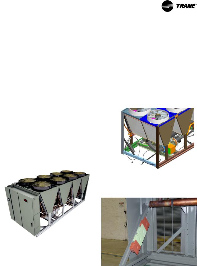
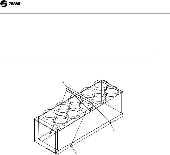
Figure 2. Typical Stealth RTAE
Accessory/Option Information
Check all the accessories and loose parts which are shipped with the unit against the shipping list. Included in these items will be water vessel drain plugs, electrical diagrams, and service literature, which are placed inside the control panel for shipment.
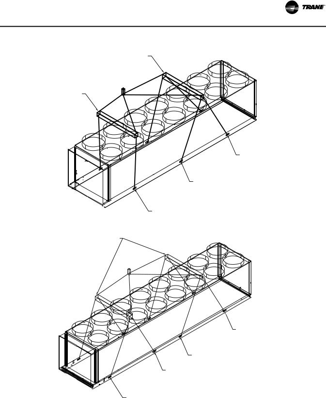
If optional elastomeric isolators are ordered with unit (model number digit 36 = 1), they are shipped mounted on diagonal supports on the end of the unit opposite control panel. See Figure 3 and Figure 4.
If optional seismic isopads are selected (model number digit 36= 2), they will be shipped inside the unit control panel.
Figure 3. Elastomeric isolator shipping location
Elastomeric Isolator
Shipping Locations
(not all isolators shown -
quantity varies with unit configuration)
Figure 4. Elastomeric isolators attached for shipping
RTAE-SVX001B-EN |
9 |

General Data
General Data
Table 1. General data table
Unit Size (tons) |
|
150 |
165 |
180 |
200 |
225 |
250 |
275 |
300 |
|
150SC |
165SC |
Compressor Model |
|
CHHSR |
CHHSR |
CHHSR |
CHHSR |
CHHSS |
CHHSS |
CHHSS |
CHHSS |
|
CHHSS |
CHHSS |
Quantity |
# |
2 |
2 |
2 |
2 |
2 |
2 |
2 |
2 |
|
1 |
1 |
|
|
|
|
|
|
|
|
|
|
|
|
|
Evaporator |
|
|
|
|
|
|
|
|
|
|
|
|
Water Storage |
(gal) |
17.5 |
18.7 |
21.9 |
23.9 |
26.6 |
28.7 |
33.0 |
36.0 |
|
17.3 |
17.3 |
|
(L) |
66.1 |
70.9 |
82.8 |
90.5 |
100.6 |
108.8 |
125.0 |
136.1 |
|
65.6 |
65.6 |
|
|
|
|
2 Pass arrangement |
|
|
|
|
|
|
||
Minimum Flow |
(gpm) |
171 |
187 |
202 |
228 |
261 |
288 |
318 |
354 |
|
169 |
169 |
|
||||||||||||
|
(l/s) |
10.8 |
11.8 |
12.7 |
14.4 |
16.5 |
18.2 |
20.1 |
22.3 |
|
10.7 |
10.7 |
Maximum Flow |
(gpm) |
626 |
684 |
742 |
835 |
957 |
1055 |
1165 |
1299 |
|
620 |
620 |
|
(l/s) |
39.5 |
43.1 |
46.8 |
52.7 |
60.4 |
66.5 |
73.5 |
81.9 |
|
39.1 |
39.1 |
|
|
|
|
3 Pass arrangement |
|
|
|
|
|
|
||
Minimum Flow |
(gpm) |
114 |
124 |
135 |
152 |
174 |
192 |
212 |
236 |
113 |
113 |
|
|
(l/s) |
7.2 |
7.8 |
8.5 |
9.6 |
11.0 |
12.1 |
13.4 |
14.9 |
7.1 |
7.1 |
|
Maximum Flow |
(gpm) |
417 |
456 |
495 |
557 |
638 |
703 |
777 |
866 |
414 |
414 |
|
|
(l/s) |
26.3 |
28.8 |
31.2 |
35.1 |
40.2 |
44.3 |
49.0 |
54.6 |
26.1 |
26.1 |
|
|
|
|
|
|
|
|
|
|
|
|
|
|
Condenser |
|
|
|
|
|
|
|
|
|
|
|
|
Qty of Coils |
|
8 |
10 |
10 |
12 |
12 |
12 |
14 |
16 |
8 |
10 |
|
Coil Length |
(in) |
78.74 |
78.74 |
78.74 |
78.74 |
78.74 |
78.74 |
78.74 |
78.74 |
78.74 |
78.74 |
|
|
(mm) |
2000 |
2000 |
2000 |
2000 |
2000 |
2000 |
2000 |
2000 |
2000 |
2000 |
|
Coil Height |
(in) |
50 |
50 |
50 |
50 |
50 |
50 |
50 |
50 |
50 |
50 |
|
|
(mm) |
1270 |
1270 |
1270 |
1270 |
1270 |
1270 |
1270 |
1270 |
1270 |
1270 |
|
Fins/Ft |
|
192 |
192 |
192 |
192 |
192 |
192 |
192 |
192 |
192 |
192 |
|
Rows |
|
3 |
3 |
3 |
3 |
3 |
3 |
3 |
3 |
3 |
3 |
|
|
|
|
|
|
|
|
|
|
|
|
|
|
Condenser Fans |
|
|
|
|
|
|
|
|
|
|
|
|
Quantity |
# |
8 |
10 |
10 |
12 |
12 |
12 |
14 |
16 |
8 |
10 |
|
Diameter |
(in) |
37.5 |
37.5 |
37.5 |
37.5 |
37.5 |
37.5 |
37.5 |
37.5 |
37.5 |
37.5 |
|
|
(mm) |
953 |
953 |
953 |
953 |
953 |
953 |
953 |
953 |
953 |
953 |
|
Total Airflow |
(cfm) |
107,392 |
134,240 |
134,240 |
161,088 |
161,088 |
161,088 |
187,936 |
214,784 |
107,392 |
132,240 |
|
|
(m3/hr) |
182,460 |
228,075 |
228,075 |
273,690 |
273,690 |
273,690 |
319,305 |
364,920 |
182,460 |
228,075 |
|
Tip Speed (ft/min) |
8700 |
8700 |
8700 |
8700 |
8700 |
8700 |
8700 |
8700 |
8700 |
8700 |
||
|
(M/S) |
44.2 |
44.2 |
44.2 |
44.2 |
44.2 |
44.2 |
44.2 |
44.2 |
44.2 |
44.2 |
|
Ambient Temperature Range |
|
|
|
|
|
|
|
|
|
|
|
Standard Ambient |
°F (°C) |
|
|
|
|
32 to 105 (0 to 40.6) |
|
|
|
|
|
Low Ambient |
°F (°C) |
|
|
|
|
0 to 105 (-17.7 to 40.6) |
|
|
|
|
|
Extreme Low Ambient |
°F (°C) |
|
|
|
|
-20 to 105 (-28.9 to 40.6) |
|
|
|
|
|
High Ambient |
°F (°C) |
|
|
|
|
32 to 125 (0 to 52) |
|
|
|
|
|
Wide Ambient |
°F (°C) |
|
|
|
|
0 to 125 (-17.7 to 52) |
|
|
|
|
|
|
|
|
|
|
|
|
|
|
|
|
|
General Unit |
|
|
|
|
|
|
|
|
|
|
|
Refrigerant |
|
|
|
|
HFC-134a |
|
|
|
HFC-134a |
||
Refrigerant Ckts |
# |
|
|
|
|
2 |
|
|
|
|
1 |
Minimum Load |
% |
20 |
18 |
17 |
15 |
20 |
18 |
16 |
15 |
30 |
27 |
Refrigerant Charge/ckt |
(lbs) |
172 |
181 |
210 |
218 |
265 |
261 |
318 |
325 |
322 |
346 |
|
(kg) |
78 |
82 |
95 |
99 |
120 |
118 |
144 |
148 |
146 |
157 |
Oil |
|
|
Trane OIL00311 (bulk)/OIL00315 (1 gal)/OIL00317 (5 gal) |
|
|
|
|||||
Oil Charge/ckt |
(gal) |
3.0 |
3.0 |
3.0 |
3.0 |
4.0 |
4.0 |
4.0 |
4.0 |
4.0 |
4.0 |
|
(L) |
11.4 |
11.4 |
11.4 |
11.4 |
15.1 |
15.1 |
15.1 |
15.1 |
15.1 |
15.1 |
|
|
|
|
|
|
|
|
|
|
|
|
10 |
RTAE-SVX001B-EN |
General Data
Drive Cooling System
Drive cooling fluid volumes are dependent on unit configuration.
•Use Table 2 for units that meet the following criteria:
•Model number digits 10, 11 = AA
•Use Table 2 for units that meet the following criteria:
•Model number digits 10, 11 = AB
•AND Digits 28, 29 = 0X
Table 2. Drive cooling with load inductor
•Use Table 2 for units that meet the following criteria:
•Model number digits 10, 11 = AC
•AND Digits 3-7 = 225, 250, 275 or 300
•AND Digit 22 = 1 or 2
•AND Digits 28, 29 = 0X
•Use Table 3 for all other unit configurations.
|
|
|
|
Unit Size (tons) |
|
|
|
|
|
|
|
|
|
Standard Length Unit |
|
|
|
|
|||
|
|
150 |
|
|
225-250 |
|
275-300 |
|||
|
|
165-200 |
|
|
||||||
|
gal |
l |
gal |
l |
|
gal |
l |
|
gal |
l |
|
|
|
|
|
|
|
|
|
||
Fluid Type |
|
|
Trane Heat Transfer Fluid CHM01023 |
|
|
|
|
|||
|
|
|
|
|
|
|
|
|
|
|
Fluid Volume |
|
|
|
|
|
|
|
|
|
|
Ckt 1 |
1.74 |
6.58 |
1.83 |
6.92 |
|
2.00 |
7.58 |
|
2.09 |
7.92 |
Ckt2 |
1.93 |
7.30 |
2.27 |
8.59 |
|
2.44 |
9.24 |
|
2.58 |
9.78 |
Total |
3.67 |
13.88 |
4.10 |
15.51 |
|
4.44 |
16.82 |
|
4.67 |
17.69 |
|
|
|
|
|
|
|
|
|
|
|
Table 3. Drive cooling without load inductor
|
|
|
|
|
|
|
|
Unit Size (tons) |
|
|
|
|
|
|
|
||
|
|
|
Standard Length Unit |
|
|
|
|
Extended Length Units(a) |
|
|
|||||||
|
|
|
|
|
|
|
|
|
|||||||||
|
150S - 165S |
|
150 |
165-250 |
275-300 |
150S - 165S |
150 |
165-250 |
275-300 |
||||||||
|
gal |
l |
|
gal |
l |
gal |
l |
gal |
l |
gal |
l |
gal |
l |
gal |
l |
gal |
l |
|
|
|
|
|
|
|
|
|
|
|
|
|
|
|
|
||
Fluid Type |
|
|
|
|
|
|
Trane Heat Transfer Fluid CHM01023 |
|
|
|
|
|
|
||||
|
|
|
|
|
|
|
|
|
|
|
|
|
|
|
|
|
|
FluidVolume |
|
|
|
|
|
|
|
|
|
|
|
|
|
|
|
|
|
Ckt 1 |
1.28 |
4.86 |
|
1.14 |
4.30 |
1.23 |
4.64 |
1.32 |
4.98 |
1.37 |
5.20 |
1.30 |
4.93 |
1.32 |
4.98 |
1.41 |
5.33 |
Ckt2 |
n/a |
n/a |
|
1.32 |
5.01 |
1.67 |
6.31 |
1.81 |
6.84 |
n/a |
n/a |
1.67 |
6.31 |
1.81 |
6.84 |
1.95 |
7.38 |
Total |
1.28 |
4.86 |
|
2.46 |
9.31 |
2.89 |
10.95 |
3.12 |
11.83 |
1.37 |
5.20 |
2.97 |
11.23 |
3.12 |
11.83 |
3.36 |
12.71 |
|
|
|
|
|
|
|
|
|
|
|
|
|
|
|
|
|
|
(a) Units are extended length if either of the following are selected: Transformer (model number digit 28 = 1)
Harmonic Filtration Option (model number digit 29 = 1)
Units without Harmonic Filtration Option or Transformer (digits 28, 29 = 0X) are standard length.
NOTICE:
Equipment Damage!
Use only Trane Heat Transfer Fluid P/N CHM01023. This fluid is a direct use concentration and is not to be diluted. Do not top off with water or any other fluid. Use of unapproved fluids, or dilution of approved fluid could result in catastrophic equipment damage.
Non-Trane approved chemicals could react with system components and result in failure. Contact a qualified service technician and your localTrane Parts Center.
Note: The use of incorrect compounds in the drive cooling system may result in scaling, erosion, corrosion or freezing.TheTrane Company warranty specifically excludes liability for corrosion, erosion, freezing or deterioration of Trane equipment.
Proper fluid level is important to the operation of the unit. See “Drive Cooling ExpansionTank,” p. 71 for fluid level check instructions.The circuit capacities are shown in tables above.
If the level is below the recommended minimum levels, contact your localTrane office.
Note: Drive cooling fluid service life is 5 years. See “Drive Cooling System,” p. 71.
RTAE-SVX001B-EN |
11 |
Pre-Installation
Unit Inspection
When unit is delivered, verify it is the correct unit and is properly equipped. Compare information on the unit nameplate with ordering and submittal information. Inspect all exterior components for visible damage. Report any apparent damage or material shortage to carrier and make a “unit damage” notation on carrier’s delivery receipt. Specify extent and type of damage found and notifyTrane Sales Office. Do not proceed with installation of a damaged unit without sales office approval.
Inspection
To protect against loss due to damage in transit, complete the following steps upon receipt of unit.
•Inspect the individual pieces of the shipment before accepting the unit. Check for obvious damage to the unit or packing material.
•Inspect the unit for concealed damage as soon as possible after delivery and before it is stored. Concealed damage must be reported within 15 days.
•If concealed damage is discovered, stop unpacking the shipment. Do not remove damaged material from the receiving location.Take photos of the damage, if possible.The owner must provide reasonable evidence that the damage did not occur after delivery.
•Notify the carrier’s terminal of the damage immediately, by phone and by mail. Request an immediate, joint inspection of the damage with the carrier and the consignee.
NotifyTrane sales representative and arrange for repair. Do not repair unit until damage is inspected by the carrier’s representative.
Storage
Extended storage of outdoor unit prior to installation requires these precautionary measures:
•Store the outdoor unit in a secure area.
•For units that have been charged with refrigerant, verify the following valves are closed on each circuit:
•Suction service valve (butterfly valve)
•Liquid line angle valve or EXV (EXV is driven closed whenever circuit is powered)
•Oil line shutoff valves to brazed plate heat exchangers
Note: Units with factory refrigerant charge (model number digit 15 = 1) are shipped with suction, liquid and oil line shutoff valves closed, isolating most of refrigerant charge in the evaporator. If unit goes directly into long term storage, it is recommended that these valve positions be confirmed.
•For units with nitrogen charge option (model number digit 15 = 2), units are shipped with valves open. If unit goes directly into storage prior to refrigerant charge, confirm all service valves are open.
N2
•At least every three months (quarterly), check the pressure in the refrigerant circuits to verify that the refrigerant charge is intact. If it is not, contact a
qualified service organization and the appropriate Trane sales office.
12 |
RTAE-SVX001B-EN |

Pre-Installation
Installation Requirements
A list of the contractor responsibilities typically associated with the unit installation process is provided in Table 4.
Table 4. Installation requirements
|
Trane Supplied |
Trane Supplied |
Field Supplied |
Type |
Trane Installed |
Field Installed |
Field Installed |
|
|
|
|
Foundation |
|
|
• Meet foundation requirements |
|
|
|
|
|
|
|
• Safety chains |
Rigging |
|
|
• Clevis connectors |
|
|
• Lifting beam |
|
|
|
|
|
|
|
|
• Spreader bar |
|
|
|
|
|
• Trane, or an agent |
|
|
|
of Trane specifically |
|
|
Disassembly/Reassembly |
authorized to perform |
|
|
start-up of Trane® |
|
|
|
(as required)(a) |
|
|
|
products (contact |
|
|
|
|
your local Trane |
|
|
|
office for pricing) |
|
|
|
|
|
|
Isolation |
|
• Elastomeric isolators |
• Elastomeric isolators (optional) |
|
(optional) |
||
|
|
|
|
|
|
|
|
|
|
|
• Circuit breakers (optional) |
|
|
|
• Electrical connections to unit mounted starter |
|
|
|
• Wiring sizes per submittal and NEC |
|
• Circuit breakers |
|
• Terminal lugs |
Electrical |
(optional) |
|
• Ground connection(s) |
|
• Unit mounted starter |
|
• BAS wiring (optional) |
|
|
|
• Control voltage wiring |
|
|
|
• Chilled water pump contactor and wiring |
|
|
|
• Option relays and wiring |
|
|
|
|
|
|
|
• Taps for thermometers and gauges |
|
|
|
• Thermometers |
|
|
|
• Water flow pressure gauges |
Water piping |
• Flow switch |
|
• Isolation and balancing valves in water piping |
|
|
|
• Vents and drain |
|
|
|
• Waterside pressure relief valves |
|
|
|
• Water strainer |
|
|
|
|
Insulation |
• Insulation |
|
• Insulation |
|
|
|
|
Water Piping Connection Components |
• Grooved pipe |
• Flange kit (optional) |
|
|
|
|
|
Other Materials |
• R-134a refrigerant |
|
|
• Dry nitrogen |
|
|
|
|
(optional) |
|
|
|
|
|
|
“Stealth™ RTAE Installation |
|
|
|
Completion Check Sheet and Request |
|
|
|
for Trane Service” |
|
|
|
(RLC-ADF002-EN, |
|
|
|
see “Log and Check Sheet,” p. 90) |
|
|
|
|
|
|
|
|
• Trane, or an agent of |
|
|
Chiller Start-up Commissioning(b) |
Trane specifically |
|
|
authorized to perform |
|
|
|
|
start-up of Trane® |
|
|
|
products |
|
|
|
|
|
|
(a)Trane, or an agent of Trane specifically authorized to perform start-up and warranty of Trane® products, will perform or have direct on-site supervision of the disassembly and reassembly work.
(b)Start-up must be performed by Trane or an agent of Trane specifically authorized to perform start-up and warranty of Trane® products. Contractor shall provide Trane (or an agent of Trane specifically authorized to perform start-up) with notice of the scheduled start-up at least two weeks prior to the scheduled start-up.
RTAE-SVX001B-EN |
13 |
Dimensions and Weights
Weights
Table 5. Weights
|
|
Standard Length Unit |
|
|
Extended Length Unit(a) |
|
||
Unit Size |
Shipping |
Operating |
Shipping |
Operating |
||||
(tons) |
lbs |
kg |
lbs |
kg |
lbs |
kg |
lbs |
kg |
|
|
|
|
|
|
|
||
|
|
|
InvisiSound™ Standard or Superior(b) |
|
|
|||
150S |
9436 |
4280 |
9596 |
4353 |
11013 |
4995 |
11173 |
5068 |
165S |
10451 |
4741 |
10611 |
4813 |
12011 |
5448 |
12171 |
5521 |
|
|
|
|
|
|
|
|
|
150 |
11333 |
5141 |
11479 |
5207 |
13492 |
6120 |
13638 |
6186 |
165 |
12377 |
5614 |
12533 |
5685 |
14532 |
6592 |
14688 |
6662 |
180 |
12698 |
5760 |
12880 |
5843 |
14853 |
6737 |
15035 |
6820 |
200 |
13808 |
6263 |
14007 |
6354 |
15991 |
7254 |
16213 |
7354 |
|
|
|
|
|
|
|
|
|
225 |
15244 |
6915 |
15466 |
7015 |
17427 |
7905 |
17649 |
8005 |
250 |
15622 |
7086 |
15861 |
7195 |
17805 |
8076 |
18044 |
8185 |
275 |
16820 |
7630 |
17095 |
7754 |
18975 |
8607 |
19250 |
8732 |
300 |
17965 |
8149 |
18265 |
8285 |
20121 |
9127 |
20421 |
9263 |
|
|
|
|
|
|
|
|
|
|
|
|
|
InvisiSound |
Ultimate(c) |
|
|
|
150S |
10236 |
4643 |
10396 |
4716 |
11813 |
5358 |
11973 |
5431 |
165S |
11251 |
5103 |
11411 |
5176 |
12811 |
5811 |
12971 |
5884 |
|
|
|
|
|
|
|
|
|
150 |
12133 |
5504 |
12279 |
5570 |
14292 |
6483 |
14438 |
6549 |
165 |
13177 |
5977 |
13333 |
6048 |
15332 |
6955 |
15488 |
7025 |
180 |
13498 |
6123 |
13680 |
6205 |
15653 |
7100 |
15835 |
7183 |
200 |
14608 |
6626 |
14807 |
6716 |
16791 |
7616 |
17013 |
7717 |
|
|
|
|
|
|
|
|
|
225 |
16044 |
7278 |
16266 |
7378 |
18227 |
8268 |
18449 |
8368 |
250 |
16422 |
7449 |
16661 |
7557 |
18605 |
8439 |
18844 |
8548 |
275 |
17620 |
7992 |
17895 |
8117 |
19775 |
8970 |
20050 |
9095 |
300 |
18765 |
8512 |
19065 |
8648 |
20921 |
9490 |
21221 |
9626 |
|
|
|
|
|
|
|
|
|
(a) Units are extended length if either of the following are selected: Transformer (model number digit 28 = 1)
Harmonic Filtration Option (model number digit 29 = 1)
Units without Harmonic Filtration Option or Transformer (digits 28, 29 = 0X) are standard length. (b)Model number digit 12 = 1 or 2
(c) Model number digit 12 = 3
Unit Dimensions
See unit submittals for specific unit dimensions and water connection locations.
Service Clearances
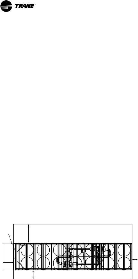
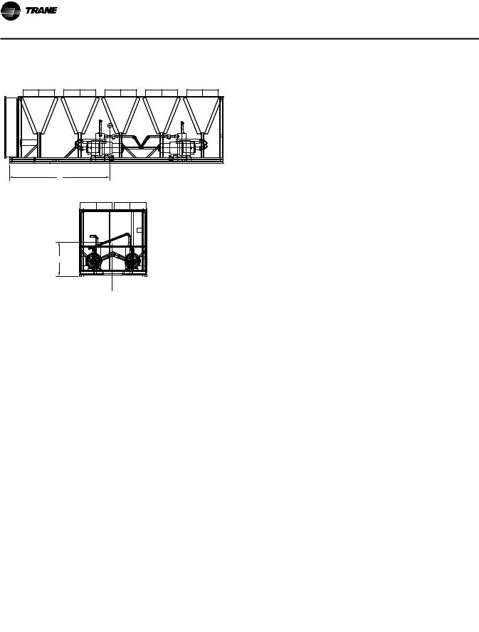
Figure 5. RTAE service clearances - top view
NO OBSTRUCTIONS ABOVE UNIT
Control |
|
|
Panel |
85” (2160mm) |
|
|
See note 2 |
|
40” |
|
|
(1016 |
24” |
|
mm) |
||
(600.1mm) |
||
|
||
See |
|
|
note 1 |
|
|
|
36” (914.4mm) |
|
14 |
|
NOTES:
1.A full 40” clearance is required in front of the control panel. Must be measured from front of panel, not end of unit base.
2.Clearance of 85” on the side of the
unit is required for coil replacement. Preferred side for coil replacement is shown (left side of unit, as facing control
panel), however either side is acceptable.
RTAE-SVX001B-EN

Installation Mechanical
Location Requirements
Sound Considerations
•Refer toTrane Engineering Bulletin Chiller Sound Ratings and Installation Guide RLC-PRB035-EN for sound consideration applications.
•Locate the unit away from sound-sensitive areas.
•Install the optional elastomeric isolators under the unit. See “Isolation and Sound Emission,” p. 20.
•Chilled water piping should not be supported by chiller frame.
•Install rubber vibration isolators in all water piping.
•Use flexible electrical conduit.
•Seal all wall penetrations.
Note: Consult an acoustical engineer for critical applications.
Foundation
Provide rigid, non-warping mounting pads or a concrete foundation of sufficient strength and mass to support the applicable operating weight (i.e., including completed piping, and full operating charges of refrigerant, oil and water). See Table 5, p. 14 for unit operating weights. Once in place, the unit must be level within 1/4” (6.4 mm) across the length and width of the unit.TheTrane Company is not responsible for equipment problems resulting from an improperly designed or constructed foundation.
Clearances
Provide enough space around the unit to allow the installation and maintenance personnel unrestricted access to all service points. See submittal drawings for the unit dimensions, to provide sufficient clearance for the opening of control panel doors and unit service. See Figure 5, p. 14 for minimum clearances. In all cases, local codes which require additional clearances will take precedence over these recommendations.
For close spacing information, see RLC-PRB037-EN.
Rigging
 WARNING
Improper Unit Lift!
Test lift unit approximately 24 inches to verify proper center of gravity lift point. To avoid dropping of unit, reposition lifting point if unit is not level. Failure to properly lift unit could result in unit dropping and possibly crushing operator/technician which could result in death or serious injury and possible equipment or property-only damage.
WARNING
Heavy Objects!
Ensure that all the lifting equipment used is properly rated for the weight of the unit being lifted. Each of the cables (chains or slings), hooks, and shackles used to lift the unit must be capable of supporting the entire weight of the unit. Lifting cables (chains or slings) may not be of the same length. Adjust as necessary for even unit lift. Other lifting arrangements could cause equipment or property damage. Failure to follow instructions above or properly lift unit could result in unit dropping and possibly crushing operator/ technician which could result in death or serious injury.
 WARNING
Proper Lifting Configuration Required!
Use only lift locations designated with label shown in Figure 6. Do NOT use locations marked with label shown in Figure 7. Use unit lifting configurations as shown in Table 6 and Figure 8, p. 16 thru Figure 10,
p. 17. Other lifting arrangements could result in death, serious injury or equipment damage.
Figure 6. Label - lift location
X39003897001A
Figure 7. Label - do not lift
X39003894001A
Important:
•Do not fork lift unit.
•See unit nameplate and/or unit submittal for total shipping weight.
•See Table 6 and Figure 8 thru Figure 10 for unit lifting configuration.
•See Table 7, p. 18 and Table 8, p. 19 for lift weights and dimensions at each lifting point locations.
•See Table 9, p. 20 for center of gravity information.
RTAE-SVX001B-EN |
15 |
Installation Mechanical
Table 6. |
Lifting configuration selection |
|
|
|||
|
|
|
|
|
|
|
|
|
Tons |
Unit Length(a) |
Lift Configuration |
See |
|
|
|
150S, 165S, 150 |
Standard and Extended |
4-point |
Figure 8, p. 16 |
|
165, 180, 200, 225, 250 |
Standard |
|||||
|
|
|||||
|
|
|
|
|
||
165, 180, 200, 225, 250 |
Extended |
6-point |
Figure 9, p. 17 |
|||
|
|
275 |
Standard |
|||
|
|
|
|
|||
|
|
|
|
|
|
|
|
|
275 |
Extended |
8-point |
Figure 10, p. 17 |
|
|
|
300 |
Standard and Extended |
|||
|
|
|
|
|||
(a) Units are extended length if either of the following are selected: Transformer (model number digit 28 = 1)
Harmonic Filtration Option (model number digit 29 = 1)
Units without Harmonic Filtration Option or Transformer (digits 28, 29 = 0X) are standard length.
Figure 8. 4-point lift configuration
96” (2438mm) Spreader Bar
Lifting Location 2
(Lifting location 3
located on other side of unit)
Control Panel
Lifting Location 1
(Lifting location 4
located on other side of unit)
16 |
RTAE-SVX001B-EN |
Installation Mechanical
Figure 9. 6-point lift configuration
96” (2438mm) Spreader Bar
96”
(2438mm) Spreader Bar
Control Panel
Lifting Location 3 (Lifting location 4 located on other side of unit)
Lifting Location 2 (Lifting location 5
located on other side of unit)
Lifting Location 1 (Lifting location 6
located on other side of unit)
Figure 10. 8-point lift configuration
96” (2438mm) Spreader Bar
Qty 2
Lifting Location 4 (Lifting location 5 located on other side of unit)
Lifting Location 3 (Lifting location 6
located on other side of unit)
Lifting Location 2 (Lifting location 5
located on other side of unit)
Control Panel
Lifting Location 1 (Lifting location 8 located on other side of unit)
RTAE-SVX001B-EN |
17 |

Installation Mechanical
Table 7. |
Lift weights by location |
|
|
|
|
|
|
|
|
|
|
|
|
||||
|
|
|
|
|
|
|
|
|
|
|
|
|
|
|
|
|
|
|
|
|
|
|
|
|
|
|
Location |
|
|
|
|
|
|
|
|
|
|
|
1 |
|
2 |
|
3 |
|
4 |
|
5 |
|
6 |
|
7 |
|
8 |
|
|
|
|
|
|
|
|
|
|
||||||||
|
Tons |
lb |
kg |
lb |
kg |
lb |
kg |
lb |
kg |
lb |
kg |
lb |
kg |
lb |
kg |
lb |
kg |
|
|
|
|
|
|
|
|
|
|
|
|
|
|
|
|
||
|
|
|
|
|
|
|
|
Standard Length Unit |
|
|
|
|
|
|
|||
|
|
|
|
|
|
|
|
|
|
|
|
|
|
|
|
|
|
|
150S |
2540 |
1152 |
2451 |
1112 |
2164 |
981 |
2281 |
1034 |
- |
- |
- |
- |
- |
- |
- |
- |
|
165S |
2656 |
1205 |
2352 |
1067 |
2730 |
1238 |
2713 |
1230 |
- |
- |
- |
- |
- |
- |
- |
- |
|
|
|
|
|
|
|
|
|
|
|
|
|
|
|
|
|
|
150 |
3426 |
1554 |
2638 |
1197 |
2234 |
1014 |
3035 |
1377 |
- |
- |
- |
- |
- |
- |
- |
- |
|
165 |
3452 |
1566 |
2876 |
1304 |
2810 |
1275 |
3239 |
1469 |
- |
- |
- |
- |
- |
- |
- |
- |
|
180 |
3528 |
1600 |
2941 |
1334 |
2896 |
1314 |
3333 |
1512 |
- |
- |
- |
- |
- |
- |
- |
- |
|
200 |
3586 |
1627 |
3325 |
1508 |
3316 |
1504 |
3581 |
1624 |
- |
- |
- |
- |
- |
- |
- |
- |
|
|
|
|
|
|
|
|
|
|
|
|
|
|
|
|
|
|
|
225 |
4003 |
1816 |
3551 |
1611 |
3617 |
1641 |
4073 |
1847 |
- |
- |
- |
- |
- |
- |
- |
- |
|
250 |
4098 |
1859 |
3637 |
1650 |
3711 |
1683 |
4176 |
1894 |
- |
- |
- |
- |
- |
- |
- |
- |
|
275 |
2484 |
1127 |
1943 |
881 |
3683 |
1671 |
3829 |
1737 |
2255 |
1023 |
2625 |
1191 |
- |
- |
- |
- |
|
300 |
2061 |
935 |
2289 |
1038 |
2515 |
1141 |
1682 |
763 |
2729 |
1238 |
3008 |
1364 |
1737 |
788 |
1943 |
881 |
|
|
|
|
|
|
|
|
|
|
|
|
|
|
|
|
|
||
|
|
|
|
|
|
|
|
Extended Length Unit(a) |
|
|
|
|
|
|
|||
|
150S |
2698 |
1224 |
2597 |
1178 |
2837 |
1287 |
2881 |
1307 |
- |
- |
- |
- |
- |
- |
- |
- |
|
165S |
2988 |
1356 |
2841 |
1289 |
3135 |
1422 |
3047 |
1382 |
- |
- |
- |
- |
- |
- |
- |
- |
|
|
|
|
|
|
|
|
|
|
|
|
|
|
|
|
|
|
150 |
3825 |
1735 |
3363 |
1525 |
2920 |
1324 |
3384 |
1535 |
- |
- |
- |
- |
- |
- |
- |
- |
|
165 |
2653 |
1203 |
2629 |
1192 |
2570 |
1166 |
1959 |
889 |
2046 |
928 |
2675 |
1213 |
- |
- |
- |
- |
|
180 |
2685 |
1218 |
2674 |
1213 |
2641 |
1198 |
1946 |
883 |
2100 |
953 |
2807 |
1273 |
- |
- |
- |
- |
|
200 |
2919 |
1324 |
2640 |
1198 |
2797 |
1269 |
2846 |
1291 |
2274 |
1032 |
2514 |
1141 |
- |
- |
- |
- |
|
|
|
|
|
|
|
|
|
|
|
|
|
|
|
|
|
|
|
225 |
3065 |
1391 |
2705 |
1227 |
3237 |
1468 |
3144 |
1426 |
2406 |
1091 |
2870 |
1302 |
- |
- |
- |
- |
|
250 |
3117 |
1414 |
2749 |
1247 |
3322 |
1507 |
3229 |
1465 |
2458 |
1115 |
2930 |
1329 |
- |
- |
- |
- |
|
275 |
2145 |
973 |
2668 |
1210 |
3279 |
1487 |
1513 |
686 |
2412 |
1094 |
2482 |
1126 |
1644 |
746 |
2831 |
1284 |
|
300 |
2056 |
933 |
2440 |
1107 |
3452 |
1566 |
2241 |
1017 |
3089 |
1401 |
2993 |
1358 |
1460 |
662 |
2389 |
1084 |
|
|
|
|
|
|
|
|
|
|
|
|
|
|
|
|
|
|
|
(a) Units are extended length if either of the following are selected: Low Harmonic Distortion Option (model number digit 29 = 1) Autotransformer (model number digit 28 = 1 or 2)
Units without Low Harmonic Distortion Option or Autotransformer (digits 28, 29 = X0) are standard length.
18 |
RTAE-SVX001B-EN |
Installation Mechanical
Table 8. |
Lifting locations (from control panel end of frame) |
|
|
|
|
|
|
|
|
|
|
|
|
|||||||||
|
|
|
|
|
|
|
|
|
|
|
|
|
|
|
|
|
|
|
|
|
|
|
|
|
|
|
|
|
|
|
|
|
Location |
|
|
|
|
|
|
|
|
|
|
||
|
|
|
|
1 |
|
|
|
3 |
|
4 |
|
|
5 |
|
|
6 |
|
|
7 |
|
|
8 |
|
|
|
|
2 |
|
|
|
|
|
|
|
|
|
|
|
|||||||
|
Tons |
|
in |
mm |
in |
mm |
in |
mm |
in |
mm |
|
in |
mm |
|
in |
mm |
|
in |
mm |
|
in |
mm |
|
|
|
|
|
|
|
|
|
|
|
|
|
|
|
|
|
|
|
|
|
||
|
|
|
|
|
|
|
|
|
Standard Length Unit |
|
|
|
|
|
|
|
|
|
||||
|
|
|
|
|
|
|
|
|
|
|
|
|
|
|
|
|
|
|
|
|
|
|
|
150S |
|
45.5 |
1156 |
45.5 |
1156 |
153.9 |
3909 |
153.9 |
3909 |
|
- |
- |
|
- |
- |
|
- |
- |
|
- |
- |
|
165S |
|
23.5 |
596 |
23.5 |
596 |
189.7 |
4818 |
189.7 |
4818 |
|
- |
- |
|
- |
- |
|
- |
- |
|
- |
- |
|
|
|
|
|
|
|
|
|
|
|
|
|
|
|
|
|
|
|
|
|
|
|
150 |
|
39.6 |
1006 |
39.6 |
1006 |
171.4 |
4353 |
171.4 |
4353 |
|
- |
- |
- |
- |
- |
- |
- |
- |
||||
165 |
|
60.4 |
1534 |
60.4 |
1534 |
224.6 |
5705 |
224.6 |
5705 |
|
- |
- |
- |
- |
- |
- |
- |
- |
||||
180 |
|
60.4 |
1534 |
60.4 |
1534 |
224.6 |
5705 |
224.6 |
5705 |
|
- |
- |
- |
- |
- |
- |
- |
- |
||||
200 |
|
53.3 |
1355 |
53.3 |
1355 |
258.7 |
6570 |
258.7 |
6570 |
|
|
- |
|
- |
- |
|
- |
- |
|
- |
- |
|
|
|
- |
|
|
|
|||||||||||||||||
|
|
|
|
|
|
|
|
|
|
|
|
|
|
|
|
|
|
|
|
|
|
|
225 |
|
53.3 |
1355 |
53.3 |
1355 |
258.7 |
6570 |
258.7 |
6570 |
|
- |
- |
- |
- |
- |
- |
- |
- |
||||
250 |
|
53.3 |
1355 |
53.3 |
1355 |
258.7 |
6570 |
258.7 |
6570 |
|
- |
- |
- |
- |
- |
- |
- |
- |
||||
275 |
|
75.8 |
1926 |
75.8 |
1926 |
190.7 |
4845 |
190.7 |
4845 |
|
311.9 |
7922 |
311.9 |
7922 |
- |
- |
- |
- |
||||
300 |
|
47.6 |
1210 |
47.6 |
1210 |
171.3 |
4350 |
171.3 |
4350 |
|
242.8 |
6168 |
242.8 |
6168 |
365.1 |
9274 |
365.1 |
9274 |
||||
|
|
|
|
|
|
|
|
|
|
|
|
|
|
|
|
|
|
|
|
|||
|
|
|
|
|
|
|
|
|
Extended Length Unit(a) |
|
|
|
|
|
|
|
|
|
||||
|
150S |
|
23.5 |
596 |
23.5 |
596 |
207.1 |
5261 |
207.1 |
5261 |
|
- |
- |
|
- |
- |
|
- |
- |
|
- |
- |
|
165S |
|
23.5 |
596 |
23.5 |
596 |
242.9 |
6170 |
242.9 |
6170 |
|
- |
- |
|
- |
- |
|
- |
- |
|
- |
- |
|
|
|
|
|
|
|
|
|
|
|
|
|
|
|
|
|
|
|
|
|
|
|
150 |
|
44.7 |
1136 |
44.7 |
1136 |
224.6 |
5705 |
224.6 |
5705 |
|
- |
- |
|
- |
- |
|
- |
- |
|
- |
- |
|
165 |
|
61.1 |
1552 |
61.1 |
1552 |
171.3 |
4350 |
171.3 |
4350 |
|
277.8 |
7057 |
277.8 |
7057 |
- |
- |
- |
- |
||||
180 |
|
61.1 |
1552 |
61.1 |
1552 |
171.3 |
4350 |
171.3 |
4350 |
|
277.8 |
7057 |
277.8 |
7057 |
- |
- |
- |
- |
||||
200 |
|
47.6 |
1210 |
47.6 |
1210 |
190.7 |
4845 |
190.7 |
4845 |
|
311.9 |
7922 |
311.9 |
7922 |
|
- |
|
- |
- |
|||
|
|
|
- |
|
||||||||||||||||||
|
|
|
|
|
|
|
|
|
|
|
|
|
|
|
|
|
|
|
|
|
|
|
225 |
|
47.6 |
1210 |
47.6 |
1210 |
190.7 |
4845 |
190.7 |
4845 |
|
311.9 |
7922 |
311.9 |
7922 |
- |
- |
- |
- |
||||
250 |
|
47.6 |
1210 |
47.6 |
1210 |
190.7 |
4845 |
190.7 |
4845 |
|
311.9 |
7922 |
311.9 |
7922 |
- |
- |
- |
- |
||||
275 |
|
75.8 |
1926 |
75.8 |
1926 |
182.0 |
4623 |
182.0 |
4623 |
|
258.5 |
6565 |
258.5 |
6565 |
365.1 |
9274 |
365.1 |
9274 |
||||
300 |
|
47.6 |
1210 |
47.6 |
1210 |
168.5 |
4280 |
168.5 |
4280 |
|
296.1 |
7520 |
296.1 |
7520 |
418.3 |
10626 |
418.3 |
10626 |
||||
|
|
|
|
|
|
|
|
|
|
|
|
|
|
|
|
|
|
|
|
|
|
|
(a) Units are extended length if either of the following are selected: Low Harmonic Distortion Option (model number digit 29 = 1) Autotransformer (model number digit 28 = 1 or 2)
Units without Low Harmonic Distortion Option or Autotransformer (digits 28, 29 = X0) are standard length.
RTAE-SVX001B-EN |
19 |
Installation Mechanical
Center of Gravity
Figure 11. Center of gravity
CG |
X |
SIDE VIEW
 CG
CG
Z
 Y
Y 
END VIEW
(Non-Control Panel End)
Table 9. |
Centers of gravity |
|
|
|
|||
|
|
|
|
|
|
|
|
|
|
CGx |
|
|
CGy |
|
CGz |
|
Tons |
in |
mm |
in |
mm |
in |
mm |
|
|
|
|
|
|
|
|
|
|
|
Standard Length Unit |
|
|
||
|
|
|
|
|
|
|
|
|
150S |
96.6 |
2454 |
43.8 |
1112 |
40.4 |
1025 |
|
165S |
110.0 |
2793 |
45.2 |
1149 |
42.8 |
1087 |
|
|
|
|
|
|
|
|
150 |
105.5 |
2679 |
43.9 |
1115 |
37.5 |
953 |
|
165 |
142.4 |
3617 |
43.9 |
1115 |
39.7 |
1008 |
|
180 |
142.8 |
3628 |
43.9 |
1115 |
39.4 |
1002 |
|
200 |
155.5 |
3951 |
43.9 |
1115 |
41.2 |
1047 |
|
|
|
|
|
|
|
|
|
225 |
156.1 |
3964 |
43.9 |
1115 |
39.8 |
1011 |
|
250 |
156.4 |
3973 |
43.9 |
1115 |
39.7 |
1008 |
|
275 |
194.1 |
4930 |
43.9 |
1115 |
41.1 |
1043 |
|
300 |
207.1 |
5260 |
43.9 |
1115 |
42.4 |
1076 |
|
|
|
|
|
|
|
|
|
|
|
|
Extended Length Unit(a) |
|
|
||
|
150S |
118.8 |
3017 |
44.1 |
1121 |
37.2 |
944 |
|
165S |
136.4 |
3464 |
44.7 |
1137 |
39.4 |
1002 |
|
|
|
|
|
|
|
|
150 |
134.7 |
3421 |
43.9 |
1115 |
33.3 |
846 |
|
165 |
169.1 |
4295 |
43.9 |
1115 |
35.4 |
898 |
|
180 |
169.9 |
4314 |
43.9 |
1115 |
35.2 |
894 |
|
200 |
181.6 |
4613 |
43.9 |
1115 |
36.9 |
937 |
|
|
|
|
|
|
|
|
|
225 |
183.6 |
4665 |
43.9 |
1115 |
36.0 |
915 |
|
250 |
184.2 |
4680 |
43.9 |
1115 |
36.0 |
913 |
|
275 |
220.2 |
5594 |
43.9 |
1115 |
37.4 |
950 |
|
300 |
232.3 |
5900 |
43.9 |
1115 |
38.7 |
984 |
|
|
|
|
|
|
|
|
|
(a) Units are extended length if either of the following are selected: Low Harmonic Distortion Option (model number digit 29 = 1) Autotransformer (model number digit 28 = 1 or 2)
UnitswithoutLowHarmonicDistortionOptionorAutotransformer(digits 28, 29 = X0) are standard length.
Isolation and Sound Emission
The most effective form of isolation is to locate the unit away from any sound sensitive area. Structurally transmitted sound can be reduced by elastomeric vibration eliminators. Spring isolators are not recommended. Consult an acoustical engineer in critical sound applications.
For maximum isolation effect, isolate water lines and electrical conduit. Wall sleeves and rubber isolated piping hangers can be used to reduce the sound transmitted through water piping.To reduce the sound transmitted through electrical conduit, use flexible electrical conduit.
State and local codes on sound emissions should always be considered. Since the environment in which a sound source is located affects sound pressure, unit placement must be carefully evaluated. Sound power levels for Stealth chillers are available on request.
Unit Isolation and Leveling
For additional reduction of sound and vibration, install the optional elastomeric isolators.
Construct an isolated concrete pad for the unit or provide concrete footings at the unit mounting points. Mount the unit directly to the concrete pads or footings.
Level the unit using the base rail as a reference.The unit must be level within 1/4-in (6 mm) over the entire length and width. Use shims as necessary to level the unit.
Elastomeric Isolators
(Optional for units without seismic rating)
Note: See unit submittal, or Table 11, p. 21 thru Table 13, p. 23 for point weights, isolator location and isolator selections.
1.Secure the isolators to the mounting surface using the mounting slots in the isolator base plate. Do not fully tighten the isolator mounting bolts at this time.
2.Align the mounting holes in the base of the unit with the threaded positioning pins on the top of the isolators.
3.Lower the unit onto the isolators and secure the isolator to the unit with a nut.
4.Level the unit carefully. Fully tighten the isolator mounting bolts.
20 |
RTAE-SVX001B-EN |
5.
Figure 12. Elastomeric isolator
5.0 in
1/2 - 13NC - 2B
 4.63 in
0.56 in
0.50 in
1.60 ± .25 in
Mounting molded in neoprene |
3.0 in |
2.75 in |
0.38 in |
Max Load |
|
Maximum |
|
(lbs) |
Color |
Deflection (in) |
Type |
|
|
|
|
2250 |
RED |
0.50 |
RDP-4 |
3000 |
GREEN |
0.50 |
RDP-4 |
|
|
|
|
Installation Mechanical
Elastomeric Isolation Pads for Seismic Option
Elastomeric pads ship inside the unit control panel.They are provided with an isolation washer and 3/4” free hole in the center of the plate.
Figure 13. Seismic isolation pad — installed
Table 10. Seismically rated elastomeric isolation pad
|
|
Dimension (in) |
|
|
Model |
Max Load |
Length |
Width |
Height |
|
|
|
|
|
B-36 |
2520 |
6 |
6 |
.625 |
|
|
|
|
|
Figure 14. Mounting point locations(a)
2 |
4 |
6 |
8 |
10 |
Control panel |
|
|
|
|
1 |
3 |
5 |
7 |
9 |
(a)Quantity of isolators varies with unit. Shorter units will not use locations 5 and 6. See submittal for actual number required for specific unit.
Table 11. Point weights
|
|
|
|
|
|
|
|
|
|
Location |
|
|
|
|
|
|
|
|
|
|
|
|
|
1 |
|
2 |
|
3 |
|
4 |
|
5 |
|
6 |
|
7 |
|
8 |
|
9 |
|
10 |
|
|
|
|
|
|
|
|
|
|
|
|
|
||||||||||
Tons |
lb |
kg |
lb |
kg |
lb |
kg |
lb |
kg |
lb |
kg |
lb |
kg |
lb |
kg |
lb |
kg |
lb |
kg |
|
lb |
kg |
|
|
|
|
|
|
|
|
|
|
|
|
|
|
|
|
|
|
|
|
|
|
|
|
|
|
|
|
|
|
|
Standard Length |
|
|
|
|
|
|
|
|
|
|
||
|
|
|
|
|
|
|
|
|
|
|
|
|
|
|
|
|
|
|
|
|
|
150S |
1731 |
785 |
1664 |
755 |
1834 |
832 |
1773 |
804 |
1219 |
553 |
1375 |
624 |
- |
- |
- |
- |
- |
- |
|
- |
- |
165S |
1666 |
756 |
1559 |
707 |
1886 |
855 |
1870 |
848 |
1914 |
868 |
1716 |
778 |
- |
- |
- |
- |
- |
- |
|
- |
- |
|
|
|
|
|
|
|
|
|
|
|
|
|
|
|
|
|
|
|
|
|
|
150 |
1452 |
659 |
1543 |
700 |
1326 |
602 |
1446 |
656 |
1464 |
664 |
1350 |
612 |
1490 |
676 |
1262 |
572 |
- |
- |
|
- |
- |
165 |
1539 |
698 |
1341 |
608 |
1622 |
736 |
1553 |
704 |
1657 |
752 |
1607 |
729 |
1522 |
690 |
1536 |
697 |
- |
- |
|
- |
- |
180 |
1536 |
697 |
1338 |
607 |
1676 |
760 |
1620 |
735 |
1709 |
775 |
1659 |
753 |
1579 |
716 |
1581 |
717 |
- |
- |
|
- |
- |
200 |
1442 |
654 |
1764 |
800 |
1696 |
769 |
1810 |
821 |
1836 |
833 |
1694 |
768 |
1986 |
901 |
1580 |
717 |
- |
- |
|
- |
- |
|
|
|
|
|
|
|
|
|
|
|
|
|
|
|
|
|
|
|
|
|
|
225 |
1430 |
649 |
1792 |
813 |
1999 |
907 |
2058 |
933 |
2111 |
958 |
1994 |
905 |
2139 |
970 |
1721 |
781 |
- |
- |
|
- |
- |
250 |
1426 |
647 |
1803 |
818 |
2064 |
936 |
2144 |
973 |
2182 |
990 |
2055 |
932 |
2195 |
996 |
1753 |
795 |
- |
- |
|
- |
- |
275 |
1624 |
737 |
1627 |
738 |
1802 |
817 |
1746 |
792 |
1795 |
814 |
1530 |
694 |
1653 |
750 |
1831 |
830 |
1577 |
715 |
|
1634 |
741 |
300 |
1634 |
741 |
1850 |
839 |
1871 |
849 |
1925 |
873 |
1898 |
861 |
1938 |
879 |
1887 |
856 |
1695 |
769 |
1752 |
795 |
|
1515 |
687 |
|
|
|
|
|
|
|
|
|
|
|
|
|
|
|
|
|
|
|
|
|
|
|
|
|
|
|
|
|
|
|
|
|
|
|
|
|
|
|
|
|
|
|
|
RTAE-SVX001B-EN |
21 |

Installation Mechanical
Table 11. |
Point weights (continued) |
|
|
|
|
|
|
|
|
|
|
|
|
|
|
||||||||
|
|
|
|
|
|
|
|
|
|
|
|
|
|
|
|
|
|
|
|
|
|
|
|
|
|
|
|
|
|
|
|
|
|
|
|
|
Location |
|
|
|
|
|
|
|
|
|
|
|
|
|
|
1 |
|
2 |
|
3 |
|
4 |
|
5 |
|
6 |
|
7 |
|
8 |
|
9 |
|
10 |
|
|
|
|
|
|
|
|
|
|
|
|
|
|
|||||||||||
|
Tons |
lb |
|
kg |
lb |
kg |
|
lb |
kg |
lb |
kg |
lb |
kg |
lb |
kg |
lb |
kg |
lb |
kg |
lb |
kg |
lb |
kg |
|
|
|
|
|
|
|
|
|
|
|
|
|
|
|
|
|
|
|
|
|
|
||
|
|
|
|
|
|
|
|
|
|
|
Extended Length Unit(a) |
|
|
|
|
|
|
|
|
||||
|
150S |
1553 |
704 |
1795 |
814 |
|
1974 |
895 |
1959 |
889 |
2088 |
947 |
1804 |
818 |
- |
- |
- |
- |
- |
- |
- |
- |
|
|
165S |
1344 |
610 |
1236 |
561 |
|
1537 |
697 |
1494 |
678 |
1686 |
765 |
1668 |
757 |
1636 |
742 |
1570 |
712 |
- |
- |
- |
- |
|
|
|
|
|
|
|
|
|
|
|
|
|
|
|
|
|
|
|
|
|
|
|
|
|
150 |
1563 |
709 |
1621 |
735 |
|
1705 |
773 |
1875 |
850 |
1952 |
885 |
1575 |
714 |
1601 |
726 |
1601 |
726 |
- |
- |
- |
- |
||
165 |
1776 |
806 |
1827 |
829 |
|
1956 |
887 |
1925 |
873 |
2058 |
933 |
1958 |
888 |
1517 |
688 |
1515 |
687 |
- |
- |
- |
- |
||
180 |
1774 |
805 |
1822 |
827 |
|
1990 |
903 |
1975 |
896 |
2128 |
965 |
2030 |
921 |
1577 |
715 |
1557 |
706 |
- |
- |
- |
- |
||
200 |
1706 |
774 |
1524 |
691 |
|
1662 |
754 |
1294 |
587 |
1938 |
879 |
1738 |
788 |
1267 |
575 |
1753 |
795 |
1457 |
661 |
1652 |
749 |
||
|
|
|
|
|
|
|
|
|
|
|
|
|
|
|
|
|
|
|
|
|
|
|
|
225 |
1857 |
842 |
1669 |
757 |
|
1844 |
836 |
1412 |
640 |
2156 |
978 |
1860 |
844 |
1378 |
625 |
1985 |
900 |
1501 |
681 |
1766 |
801 |
||
250 |
1852 |
840 |
1664 |
755 |
|
1885 |
855 |
1439 |
653 |
2219 |
1006 |
1936 |
878 |
1438 |
652 |
2046 |
928 |
1530 |
694 |
1795 |
814 |
||
275 |
1874 |
850 |
1860 |
844 |
|
1626 |
737 |
1700 |
771 |
2204 |
1000 |
2101 |
953 |
2017 |
915 |
2131 |
967 |
1820 |
826 |
1642 |
745 |
||
300 |
1946 |
883 |
1826 |
828 |
|
1854 |
841 |
1795 |
814 |
2143 |
972 |
2106 |
955 |
2408 |
1092 |
2338 |
1060 |
1808 |
820 |
1898 |
861 |
||
|
|
|
|
|
|
|
|
|
|
|
|
|
|
|
|
|
|
||||||
|
(a) Units are extended length if either of the following are selected: |
|
|
|
|
|
|
|
|
|
|
|
|
||||||||||
|
|
Low Harmonic Distortion Option (model number digit 29 = 1) |
|
|
|
|
|
|
|
|
|
|
|
||||||||||
|
|
Autotransformer (model number digit 28 = 1 or 2) |
|
|
|
|
|
|
|
|
|
|
|
|
|
||||||||
|
Units without Low Harmonic Distortion Option or Autotransformer (digits 28, 29 = X0) are standard length. |
|
|
|
|
|
|
||||||||||||||||
Table 12. |
Isolator locations(a) |
|
|
|
|
|
|
|
|
|
|
|
|
|
|
|
|
||||||
|
|
|
|
|
|
|
|
|
|
|
|
|
|
|
|
|
|
|
|
|
|
|
|
|
|
|
|
|
|
|
|
|
|
|
|
|
Location |
|
|
|
|
|
|
|
|
|
|
|
|
|
|
1 |
|
2 |
|
3 |
|
|
|
|
|
|
|
|
|
|
|
|
|
|
|
|
|
|
|
|
|
|
4 |
|
5 |
|
6 |
|
7 |
|
8 |
|
9 |
|
10 |
||||
|
Tons |
in |
|
mm |
in |
mm |
|
in |
mm |
in |
mm |
in |
mm |
in |
mm |
in |
mm |
in |
mm |
in |
mm |
in |
mm |
|
|
|
|
|
|
|
|
|
|
|
|
|
|
|
|
|
|
|
|
|
|
|
|
|
|
|
|
|
|
|
|
|
|
|
|
|
Standard Length |
|
|
|
|
|
|
|
|
||
|
|
|
|
|
|
|
|
|
|
|
|
|
|
|
|
|
|
|
|
|
|
|
|
|
150S |
23.6 |
600 |
27.6 |
700 |
|
102.4 |
2600 |
94.5 |
2400 |
187.0 |
4750 |
187.0 |
4750 |
- |
- |
- |
- |
- |
- |
- |
- |
|
|
165S |
15.7 |
400 |
23.0 |
585 |
|
98.4 |
2500 |
102.2 |
2595 |
196.9 |
5000 |
204.7 |
5200 |
- |
- |
- |
- |
- |
- |
- |
- |
|
|
|
|
|
|
|
|
|
|
|
|
|
|
|
|
|
|
|
|
|
|
|
|
|
150 |
24.4 |
620 |
11.8 |
300 |
|
47.2 |
1200 |
82.7 |
2100 |
100.4 |
2550 |
153.5 |
3900 |
188.2 |
4780 |
188.2 |
4780 |
- |
- |
- |
- |
||
165 |
17.7 |
450 |
23.0 |
585 |
|
98.6 |
2505 |
102.2 |
2595 |
155.5 |
3950 |
190.6 |
4840 |
242.1 |
6150 |
242.9 |
6170 |
- |
- |
- |
- |
||
180 |
17.7 |
450 |
23.0 |
585 |
|
98.6 |
2505 |
102.2 |
2595 |
155.5 |
3950 |
190.6 |
4840 |
242.1 |
6150 |
242.9 |
6170 |
- |
- |
- |
- |
||
200 |
23.6 |
600 |
23.6 |
600 |
|
102.4 |
2600 |
137.8 |
3500 |
155.5 |
3950 |
198.8 |
5050 |
255.9 |
6500 |
263.8 |
6700 |
- |
- |
- |
- |
||
|
|
|
|
|
|
|
|
|
|
|
|
|
|
|
|
|
|
|
|
|
|
|
|
225 |
23.6 |
600 |
23.6 |
600 |
|
102.4 |
2600 |
137.8 |
3500 |
155.5 |
3950 |
198.8 |
5050 |
255.9 |
6500 |
263.8 |
6700 |
- |
- |
- |
- |
||
250 |
23.6 |
600 |
23.6 |
600 |
|
102.4 |
2600 |
137.8 |
3500 |
155.5 |
3950 |
198.8 |
5050 |
255.9 |
6500 |
263.8 |
6700 |
- |
- |
- |
- |
||
275 |
21.7 |
550 |
18.9 |
480 |
|
141.3 |
3590 |
125.2 |
3180 |
196.1 |
4980 |
236.2 |
6000 |
236.2 |
6000 |
259.8 |
6598 |
328.0 |
8330 |
324.4 |
8240 |
||
300 |
19.7 |
500 |
27.6 |
700 |
|
143.1 |
3634 |
143.1 |
3634 |
202.4 |
5142 |
235.6 |
5984 |
257.9 |
6551 |
296.6 |
7534 |
347.8 |
8834 |
339.5 |
8624 |
||
|
|
|
|
|
|
|
|
|
|
|
|
|
|
|
|
|
|
|
|
|
|
||
|
|
|
|
|
|
|
|
|
|
|
|
Extended Length Unit(b) |
|
|
|
|
|
|
|
|
|||
|
150S |
19.7 |
500 |
15.7 |
400 |
|
102.4 |
2600 |
133.9 |
3400 |
204.7 |
5200 |
208.7 |
5300 |
- |
- |
- |
- |
- |
- |
- |
- |
|
|
165S |
23.6 |
600 |
23.6 |
600 |
|
86.6 |
2200 |
78.7 |
2000 |
149.6 |
3800 |
157.5 |
4000 |
259.8 |
6600 |
259.8 |
6600 |
- |
- |
- |
- |
|
|
|
|
|
|
|
|
|
|
|
|
|
|
|
|
|
|
|
|
|
|
|
|
|
150 |
25.0 |
635 |
23.6 |
600 |
|
84.6 |
2150 |
98.4 |
2500 |
147.6 |
3750 |
190.9 |
4850 |
240.2 |
6100 |
240.2 |
6100 |
- |
- |
- |
- |
||
165 |
19.7 |
500 |
19.7 |
500 |
|
129.9 |
3300 |
129.9 |
3300 |
204.7 |
5200 |
234.3 |
5950 |
293.3 |
7450 |
299.2 |
7600 |
- |
- |
- |
- |
||
180 |
19.7 |
500 |
19.7 |
500 |
|
129.9 |
3300 |
129.9 |
3300 |
204.7 |
5200 |
234.3 |
5950 |
293.3 |
7450 |
299.2 |
7600 |
- |
- |
- |
- |
||
200 |
25.6 |
650 |
19.7 |
500 |
|
118.1 |
3000 |
98.4 |
2500 |
208.7 |
5300 |
196.9 |
5000 |
255.9 |
6500 |
255.9 |
6500 |
315.0 |
8000 |
315.0 |
8000 |
||
|
|
|
|
|
|
|
|
|
|
|
|
|
|
|
|
|
|
|
|
|
|
|
|
225 |
25.6 |
650 |
19.7 |
500 |
|
118.1 |
3000 |
98.4 |
2500 |
208.7 |
5300 |
196.9 |
5000 |
255.9 |
6500 |
255.9 |
6500 |
315.0 |
8000 |
315.0 |
8000 |
||
250 |
25.6 |
650 |
19.7 |
500 |
|
118.1 |
3000 |
98.4 |
2500 |
208.7 |
5300 |
196.9 |
5000 |
255.9 |
6500 |
255.9 |
6500 |
315.0 |
8000 |
315.0 |
8000 |
||
275 |
6.3 |
|
160 |
9.8 |
250 |
|
177.2 |
4500 |
139.8 |
3550 |
198.8 |
5050 |
242.1 |
6150 |
309.1 |
7850 |
313.0 |
7950 |
354.3 |
9000 |
370.1 |
9400 |
|
300 |
9.8 |
|
250 |
9.8 |
250 |
|
177.2 |
4500 |
139.8 |
3550 |
206.7 |
5250 |
242.1 |
6150 |
311.8 |
7920 |
313.4 |
7960 |
393.7 10000 |
393.7 10000 |
|||
|
|
|
|
|
|
|
|
|
|
|
|
|
|
|
|
|
|
|
|
|
|
|
|
(a) Dimensions are referenced from end of frame on the control panel side. (b)Units are extended length if either of the following are selected:
Low Harmonic Distortion Option (model number digit 29 = 1) Autotransformer (model number digit 28 = 1 or 2)
Units without Low Harmonic Distortion Option or Autotransformer (digits 28, 29 = X0) are standard length.
22 |
RTAE-SVX001B-EN |
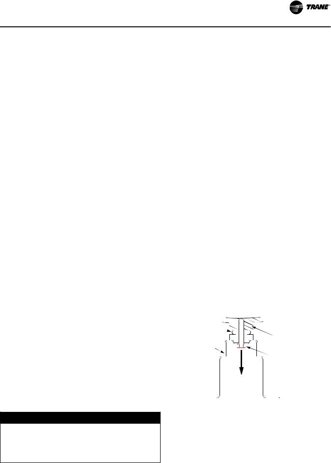
Installation Mechanical
Table 13. |
Isolator selections |
|
|
|
|
|
|
|
|
|
|
|
|
|
|
|
||||
|
|
|
|
|
|
|
|
|
|
|
|
|
|
|
|
|
|
|
|
|
|
|
|
|
|
|
|
|
|
|
Location |
|
|
|
|
|
|
|
|
||
|
Tons |
|
1 |
|
|
3 |
|
4 |
|
5 |
|
6 |
|
7 |
|
8 |
|
9 |
|
10 |
|
|
2 |
|
|
|
|
|
|
|
|
||||||||||
|
|
|
|
|
|
|
|
|
|
|
|
|
|
|
|
|
|
|
|
|
|
|
|
|
|
|
|
|
|
Standard Length Unit |
|
|
|
|
|
|
|
|
|||
|
|
|
|
|
|
|
|
|
|
|
|
|
|
|
|
|
|
|
|
|
|
150S |
|
Red 62 |
Red 62 |
|
Red 62 |
|
Red 62 |
|
Red 62 |
|
Red 62 |
|
- |
- |
|
- |
- |
||
|
165S |
|
Red 62 |
Red 62 |
|
Red 62 |
|
Red 62 |
|
Red 62 |
|
Red 62 |
|
- |
- |
|
- |
- |
||
|
|
|
|
|
|
|
|
|
|
|
|
|
|
|
|
|
|
|
|
|
150 |
|
Red 62 |
Red 62 |
|
Green 63 |
|
Green 63 |
|
Green 63 |
|
Green 63 |
|
Red 62 |
|
Red 62 |
|
- |
- |
||
165 |
|
Red 62 |
Red 62 |
|
Green 63 |
|
Green 63 |
|
Green 63 |
|
Green 63 |
|
Red 62 |
|
Red 62 |
|
- |
- |
||
180 |
|
Red 62 |
Red 62 |
|
Green 63 |
|
Green 63 |
|
Green 63 |
|
Green 63 |
|
Red 62 |
|
Red 62 |
|
- |
- |
||
|
200 |
|
Red 62 |
Red 62 |
|
Green 63 |
|
Green 63 |
|
Green 63 |
|
Green 63 |
|
Red 62 |
|
Red 62 |
|
- |
- |
|
|
225 |
|
Red 62 |
Red 62 |
|
Green 63 |
|
Green 63 |
|
Green 63 |
|
Green 63 |
|
Red 62 |
|
Red 62 |
|
- |
- |
|
250 |
|
Red 62 |
Red 62 |
|
Green 63 |
|
Green 63 |
|
Green 63 |
|
Green 63 |
|
Red 62 |
|
Red 62 |
|
- |
- |
||
|
|
|
|
|
|
|
|
|
|
|
|
|
|
|
|
|
|
|
|
|
275 |
|
Red 62 |
Red 62 |
|
Green 63 |
|
Green 63 |
|
Green 63 |
|
Green 63 |
|
Green 63 |
|
Green 63 |
|
Red 62 |
|
Red 62 |
|
300 |
|
Red 62 |
Red 62 |
|
Green 63 |
|
Green 63 |
|
Green 63 |
|
Green 63 |
|
Green 63 |
|
Green 63 |
|
Red 62 |
|
Red 62 |
|
|
|
|
|
|
|
|
|
Extended Length Unit(a) |
|
|
|
|
|
|
|
|
||||
|
150S |
|
Red 62 |
Red 62 |
|
Green 63 |
|
Green 63 |
|
Green 63 |
|
Red 62 |
|
- |
- |
|
- |
- |
||
|
165S |
|
Red 62 |
Red 62 |
|
Red 62 |
|
Red 62 |
|
Red 62 |
|
Red 62 |
|
Red 62 |
|
Red 62 |
|
- |
- |
|
|
|
|
|
|
|
|
|
|
|
|
|
|
|
|
|
|
|
|
|
|
150 |
|
Red 62 |
Red 62 |
|
Green 63 |
|
Green 63 |
|
Green 63 |
|
Green 63 |
|
Red 62 |
|
Red 62 |
|
- |
- |
||
165 |
|
Red 62 |
Red 62 |
|
Green 63 |
|
Green 63 |
|
Green 63 |
|
Green 63 |
|
Red 62 |
|
Red 62 |
|
- |
- |
||
180 |
|
Red 62 |
Red 62 |
|
Green 63 |
|
Green 63 |
|
Green 63 |
|
Green 63 |
|
Red 62 |
|
Red 62 |
|
- |
- |
||
|
200 |
|
Red 62 |
Red 62 |
|
|
|
|
|
|
|
|
|
|
|
|
|
|
|
|
|
|
Green 63 |
|
Green 63 |
|
Green 63 |
|
Green 63 |
|
Green 63 |
|
Green 63 |
|
Red 62 |
|
Red 62 |
||||
|
225 |
|
Red 62 |
Red 62 |
|
Green 63 |
|
Green 63 |
|
Green 63 |
|
Green 63 |
|
Green 63 |
|
Green 63 |
|
Red 62 |
|
Red 62 |
250 |
|
Red 62 |
Red 62 |
|
Green 63 |
|
Green 63 |
|
Green 63 |
|
Green 63 |
|
Green 63 |
|
Green 63 |
|
Red 62 |
|
Red 62 |
|
275 |
|
Red 62 |
Red 62 |
|
Green 63 |
|
Green 63 |
|
Green 63 |
|
Green 63 |
|
Green 63 |
|
Green 63 |
|
Red 62 |
|
Red 62 |
|
|
300 |
|
Red 62 |
Red 62 |
|
Green 63 |
|
Green 63 |
|
Green 63 |
|
Green 63 |
|
Green 63 |
|
Green 63 |
|
Red 62 |
|
Red 62 |
|
|
|
|
|
|
|
|
|
|
|
|
|
|
|
|
|
|
|
|
|
(a) Units are extended length if either of the following are selected: Low Harmonic Distortion Option (model number digit 29 = 1) Autotransformer (model number digit 28 = 1 or 2)
Units without Low Harmonic Distortion Option or Autotransformer (digits 28, 29 = X0) are standard length.
Compressor Shipping Bolt Removal
Units with InvisiSound™ Ultimate Option (Model Number Digit 12 = 3)
For chillers built with InvisiSound Ultimate option, compressor shipping bolts must be removed to assure minimum noise during operation. Use a 24mm socket to remove the (3) M15 x 75mm shipping bolts for each compressor.They are located under compressor mounting feet. See Figure 15.
Important:
•DO NOT DISCARD SHIPPING BOLTS. Store bolts in the control panel for future use.
•All shipping bolts MUST be reinstalled prior to compressor removal or unit move.
NOTICE:
Equipment Damage!
Do not remove compressor or move unit without reattaching compressor shipping bolts. Failure to reinstall bolts could cause shifting of parts and result in equipment damage.
Figure 15. Compressor shipping bolt removal
Isolator |
|
|
Compressor |
Compressor |
|
Mounting |
|
Foot |
Shipping Bolt |
|
Drainage
Locate the unit near a large capacity drain for water vessel drain-down during shutdown or repair. Evaporators are provided with drain connections. A vent on top of evaporator waterbox prevents vacuum by allowing air into evaporator for complete drainage. All local and national codes apply.
RTAE-SVX001B-EN |
23 |
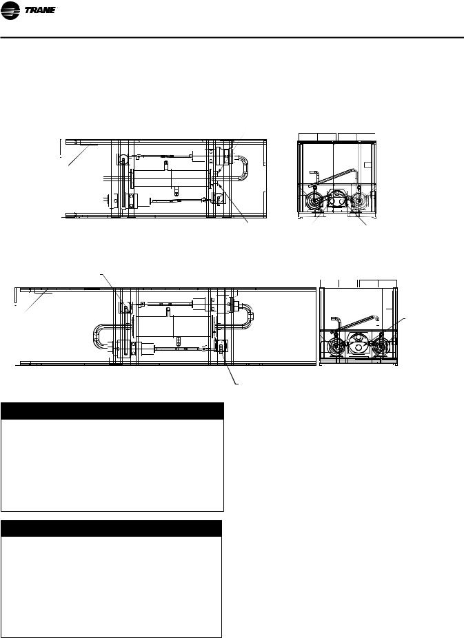
Installation Mechanical
Evaporator Piping
RTAE units are available with 2 or 3 pass configurations. See Figure 16.
Figure 16. Evaporator pass configurations
2-Pass Evaporators
Control Panel End

Top View (Condenser removed for clarity)
Inlet Water
Connection
Outlet Water |
Outlet |
Inlet |
|
Connection |
|||
|
End View |
||
|
|
(Non-control panel end)
3-Pass Evaporators
Outlet Waterbox
Control Panel End


Inlet Waterbox (Outlet waterbox opposite end)
Top View |
|
End View |
|
Inlet Waterbox |
(Non-control panel end) |
||
(Condenser removed for clarity) |
|||
|
|
NOTICE:
Proper Water Treatment!
The use of untreated or improperly treated water could result in scaling, erosion, corrosion, algae or slime. It is recommended that the services of a qualified water treatment specialist be engaged to determine what water treatment, if any, is required. Trane assumes no responsibility for equipment failures which result from untreated or improperly treated water, or saline or brackish water.
NOTICE:
Evaporator Damage!
The chilled water connections to the evaporator are to be “victaulic” type connections. Do not attempt to weld these connections, as the heat generated from welding can cause microscopic and macroscopic fractures on the cast iron waterboxes that can lead to premature failure of the waterbox. To prevent damage to chilled water components, do not allow evaporator pressure (maximum working pressure) to exceed 150 psig (10.5 bar).
Evaporator water connections are grooved.
Thoroughly flush all water piping to the unit before making the final piping connections to the unit.
Components and layout will vary slightly, depending on the location of connections and the water source.
A vent is provided on the top of the evaporator at the chilled water inlet. Be sure to provide additional vents at high points in the piping to bleed air from the chilled water system. Install necessary pressure gauges to monitor the entering and leaving chilled water pressures.
Provide shutoff valves in lines to the gauges to isolate them from the system when they are not in use. Use rubber vibration eliminators to prevent vibration transmission through the water lines.
If desired, install thermometers in the lines to monitor entering and leaving water temperatures. Install a balancing valve in the leaving water line to control water flow balance. Install shutoff valves on both the entering and leaving water lines so that the evaporator can be isolated for service
24 |
RTAE-SVX001B-EN |
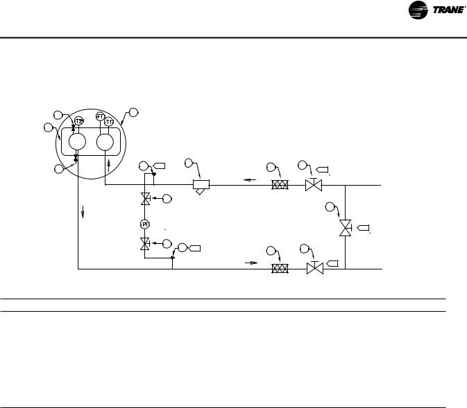
|
|
|
|
|
|
|
Installation Mechanical |
Evaporator Piping Components |
|
|
operating safety. SeeThese components and their general |
||||
Piping components include all devices and controls used |
locations are given below. |
||||||
|
|
||||||
to provide proper water system operation and unit |
|
|
|||||
Figure 17. Typical Stealth™ water piping |
|
|
|
|
|||
|
6 |
4 |
|
|
|
|
|
|
|
|
|
|
|
|
|
|
5 |
|
|
|
|
|
|
|
8 |
|
B |
|
7 |
3 |
2 |
|
|
|
|
|
|
A |
|
|
|
|
2 |
|
|
|
|
|
|
|
|
|
|
|
1 |
|
|
|
|
|
|
|
A |
|
|
|
2 |
8 |
C |
|
2 |
|
|
|
|
3 |
|||
|
|
|
|
|
|
|
|
|
|
|
|
|
|
|
A |
Table 14. Water piping components |
|
|
|
|
|
||
Item |
Description |
|
|
|
Item |
Description |
|
1 |
Bypass Valve |
|
|
|
Pi |
Pressure Gauge |
|
2 |
Isolation Valve |
|
|
|
FT |
Water Flow Switch |
|
3 |
Vibration Eliminator |
|
|
|
T1 |
Evap Water Inlet Temp Sensor |
|
4 |
Evaporator - End View (2-pass) |
|
|
T2 |
Evap Water Outlet Temp Sensor |
||
5 |
Evaporator Waterbox (2-pass) |
|
|
|
|
NOTES |
|
6 |
Vent |
|
|
|
A |
Isolate unit for initial water loop cleaning |
|
7 |
Strainer |
|
|
|
B |
Vent must be installed at the high point of the line |
|
8 |
Drain |
|
|
|
C |
Drain must be installed at the low point of the line |
|
Entering Chilled Water Piping
•Air vents (to bleed air from system).
•Water pressure gauges with shutoff valves.
•Vibration eliminators.
•Shutoff (isolation) valves.Thermometers (if desired).
•Clean-out tees.
•Pipe strainer.
Leaving Chilled Water Piping
•Air vents (to bleed air from system).
•Water pressure gauges with shutoff valves.
•Vibration eliminators.
•Shutoff (isolation) valves.
•Thermometers.
•Clean-out tees.
•Balancing valve.
Drains
A 1/2” drain connection is located under outlet end of evaporator waterbox for drainage during unit servicing. A shutoff valve must be installed on drain line.
Pressure Gauges
Install field-supplied pressure components as shown in Figure 17, p. 25. Locate pressure gauges or taps in a straight run of pipe; avoid placement near elbows, etc. Be sure to install the gauges at the same elevation on each shell if the shells have opposite-end water connections.
To read manifolded pressure gauges, open one valve and close the other (depending upon the reading desired).This eliminates errors resulting from differently calibrated gauges installed at unmatched elevations.
RTAE-SVX001B-EN |
25 |
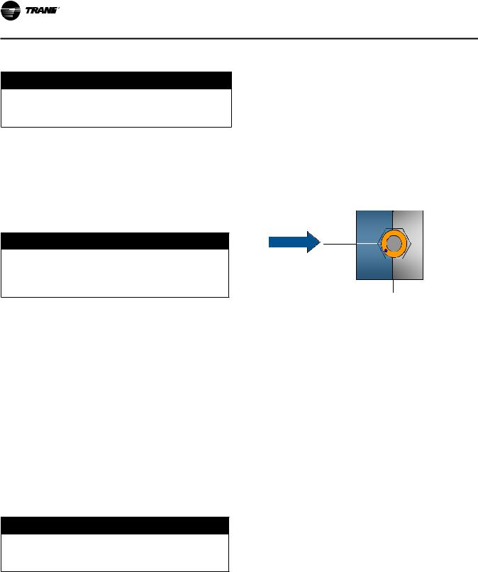
Installation Mechanical
Pressure Relief Valves
NOTICE:
Evaporator Damage!
To prevent shell damage, install pressure relief valves in the evaporator water system.
Indexing Flow Switch
To properly index the flow switch, the following requirements must be met:
•The dot must be at a position no greater than 90° off Index.
•The torque must be between 22 ft-lb minimum and 74 ft-lb maximum.
Install a water pressure relief valve in the evaporator inlet piping between the evaporator and the inlet shutoff valve, as shown in Figure 17, p. 25. Water vessels with closecoupled shutoff valves have a high potential for hydrostatic pressure buildup on a water temperature increase. Refer to applicable codes for relief valve installation guidelines.
Evaporator Flow Switch
NOTICE:
Equipment Damage!
Flow switch is on a 24V circuit. Do NOT apply 120V to the flow switch. Incorrect voltage application could cause damage to the flow switch.
The flow switch is factory-installed and programmed based on the operating conditions submitted with the order.The leaving evaporator temperature, fluid type and fluid concentration affect the selected flow switch. If the operating conditions on the job site change, the flow switch may need to be replaced. Contact your localTrane Sales office for more information.
The sensor head includes 3 LEDs, two yellow and one green.Wait 15 seconds after power is applied to the sensor before evaluating LEDs for flow status. When wired correctly and flow is established, only the green LED should be lit. Following are the LED indicators:
•A minimum distance of 5x pipe diameter must be maintained between flow switch and any bends, valves, changes in cross sections, etc.
Figure 18. Proper flow switch indexing
Top View
Flow
Index
The flow switch must have the dot
in the shaded area to the left of this line for proper indexing (±90° off Index)
•Green ON, both yellow OFF — Flow
•Green and outside yellow ON — No Flow
•Center yellow ON continuously — Miswire
Factory installed jumper wire W11 must be removed if using auxiliary contacts and/or additional proof of flow. See schematics in RTAE-SVE01*-EN for more details.
NOTICE:
Equipment Damage!
Incorrect wiring of auxiliary contacts could cause equipment damage.
If using auxiliary flow sensing, both yellow LEDs come on initially when flow is stopped.The center yellow LED will turn off after approximately 7 seconds.The LED indicators are otherwise the same as indicated above.
26 |
RTAE-SVX001B-EN |

Installation Mechanical
Evaporator Waterside Pressure Drop Curves
Figure 19. Evaporator waterside pressure drop curve — 2-pass
|
50 |
300T |
|
|
|
|
|
|
|
47.5 |
|
|
|
|
|
|
|
|
|
|
|
|
|
|
|
|
|
45 |
275T |
|
|
|
|
|
|
|
|
|
|
|
|
|
|
|
|
42.5 |
250T |
|
|
|
|
|
|
|
40 |
225T |
|
|
|
|
|
|
|
|
|
|
|
|
|
|
|
|
37.5 |
200T |
|
|
|
|
|
|
|
35 |
|
|
|
|
|
|
|
H2O) |
|
|
|
|
|
|
|
|
32.5 |
185T |
|
|
|
|
|
|
|
|
|
|
|
|
|
|
||
30 |
165T |
|
|
|
|
|
|
|
(ft. |
|
|
|
|
|
|
||
27.5 |
|
|
|
|
|
|
|
|
Drop |
150T |
|
|
|
|
|
|
|
|
|
|
|
|
|
|
||
25 |
|
|
|
|
|
|
|
|
Pressure |
150S, |
|
|
|
|
|
|
|
22.5 |
|
|
|
|
|
|
||
165S |
|
|
|
|
|
|
||
20 |
|
|
|
|
|
|
|
|
17.5 |
|
|
|
|
|
|
|
|
|
|
|
|
|
|
|
|
|
|
15 |
|
|
|
|
|
|
|
|
12.5 |
|
|
|
|
|
|
|
|
10 |
|
|
|
|
|
|
|
|
7.5 |
|
|
|
|
|
|
|
|
5 |
|
|
|
|
|
|
|
|
2.5 |
|
|
|
|
|
|
|
|
0 |
|
|
|
|
|
|
|
|
0 |
200 |
400 |
600 |
800 |
1000 |
1200 |
1400 |
Water Flow (GPM)
RTAE-SVX001B-EN |
27 |
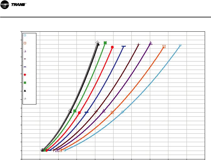
Installation Mechanical
Figure 20. Evaporator waterside pressure drop curve — 3-pass |
|
|
|
|
|
||||||
|
75 |
300T |
|
|
|
|
|
|
|
|
|
|
|
|
|
|
|
|
|
|
|
|
|
|
70 |
275T |
|
|
|
|
|
|
|
|
|
|
|
|
|
|
|
|
|
|
|
|
|
|
65 |
250T |
|
|
|
|
|
|
|
|
|
|
|
|
|
|
|
|
|
|
|
|
|
|
60 |
225T |
|
|
|
|
|
|
|
|
|
|
|
|
|
|
|
|
|
|
|
|
|
|
55 |
200T |
|
|
|
|
|
|
|
|
|
|
|
|
|
|
|
|
|
|
|
|
|
H2O) |
50 |
185T |
|
|
|
|
|
|
|
|
|
45 |
165T |
|
|
|
|
|
|
|
|
|
|
(ft. |
|
|
|
|
|
|
|
|
|
||
|
|
|
|
|
|
|
|
|
|
|
|
Drop |
40 |
150T |
|
|
|
|
|
|
|
|
|
|
150S, |
|
|
|
|
|
|
|
|
|
|
Pressure |
35 |
|
|
|
|
|
|
|
|
|
|
|
165S |
|
|
|
|
|
|
|
|
|
|
30 |
|
|
|
|
|
|
|
|
|
|
|
|
|
|
|
|
|
|
|
|
|
|
|
|
25 |
|
|
|
|
|
|
|
|
|
|
|
20 |
|
|
|
|
|
|
|
|
|
|
|
15 |
|
|
|
|
|
|
|
|
|
|
|
10 |
|
|
|
|
|
|
|
|
|
|
|
5 |
|
|
|
|
|
|
|
|
|
|
|
0 |
|
|
|
|
|
|
|
|
|
|
|
0 |
100 |
200 |
300 |
400 |
500 |
600 |
700 |
800 |
900 |
1000 |
Water Flow (GPM)
28 |
RTAE-SVX001B-EN |
Installation Mechanical
Freeze Protection
One or more of the ambient freeze avoidance methods in Table 15 must be used to protect the Stealth chiller from ambient freeze damage.
Table 15. RTAC freeze avoidance methods
|
Protects to |
|
Method |
ambient |
|
temperature |
Notes |
|
|
|
|
|
|
• Heaters alone will provide low ambient protection down to -20°F (-29°C), but will NOT |
|
|
protect the evaporator from freezing as a result of charge migration. Therefore, it is |
|
|
required that water pump control be used in conjunction with heaters. |
|
|
• Heaters are factory-installed on the evaporator and water piping and will protect them from freezing |
|
|
• Install heat tape on all water piping, pumps, and other components that may be damaged if exposed |
|
|
to freezing temperatures. Heat tape must be designed for low ambient temperature applications. Heat |
|
|
tape selection should be based on the lowest expected ambient temperature. |
|
|
• Tracer™ UC800 controller can start the pump when freezing conditions are detected. For this option |
|
|
the pump must to be controlled by the Stealth unit and this function must be validated. |
|
|
• Water circuit valves need to stay open at all times. |
|
|
• Water pump control and heater combination will protect the evaporator down to any |
Water Pump Control |
Down to -20°F |
ambient temperature provided power is available to the pump and the controller. This |
AND Heaters |
option will NOT protect the evaporator in the event of a power failure to the chiller unless |
|
|
|
backup power is supplied to the necessary components. |
|
|
• When no chiller operation is possible and the pump is already off, UC800 pump control for freeze |
|
|
protection will command the pump to turn: |
|
|
ON if average of the evaporator entering water temperature, the evaporator leaving water |
|
|
temperature, and the evaporator refrigerant pool temperature is less than Low Evaporator Refrigerant |
|
|
Temperature Cutout (LERTC) + 4°F for a period of time. |
|
|
OFF again if the evaporator refrigerant pool temperature rises above the LERTC + 6°F for a period |
|
|
of time. |
|
|
Note: Time period referenced for ON and Off conditions above is dependent on past running conditions |
|
|
and present temperatures measured. |
|
|
ON if entering OR leaving water temperature< LWTC for 30°F-sec (17°C-sec) |
|
|
OFF again if water temperature > LWTC for 30 min |
|
|
|
|
Varies. |
• Freeze protection can be accomplished by adding sufficient glycol to protect against freezing below |
|
See “Low |
the lowest ambient expected. |
|
Evaporator |
• Use of glycol type antifreeze reduces the cooling capacity of the unit and must be |
Freeze Inhibitor |
Refrigerant Cutout, |
considered in the design of the system specifications. |
|
Glycol |
|
|
Requirements,” |
|
|
p. 30 |
|
|
|
|
|
|
• Shut off the power supply to the unit and to all heaters. |
Drain Water Circuit |
Below -20°F |
• Purge the water circuit. |
|
|
• Blow out the evaporator to ensure no liquid is left in the evaporator. |
|
|
|
NOTICE:
Evaporator Damage!
If insufficient concentration or no glycol is used, the evaporator water flow must be controlled by the UC800 AND heaters must be used to avoid catastrophic damage to the evaporator due to freezing. It is the responsibility of the installing contractor and/or the customer to ensure that a pump will start when called upon by the chiller controls. Refer to RLC-PRB012-EN. Even with water pump control, a power loss of as little as 15 minutes under freezing conditions can damage the evaporator. Only the proper addition of freeze inhibitor or complete drainage of the water circuit can ensure no evaporator damage in the event of a power failure.
RTAE-SVX001B-EN |
29 |
Loading...