


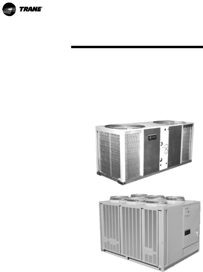
Air-Cooled
Liquid Chillers
10 to 60Tons
April 2004 |
CG-PRC007-EN |
Introduction
Air-Cooled
Liquid Chillers
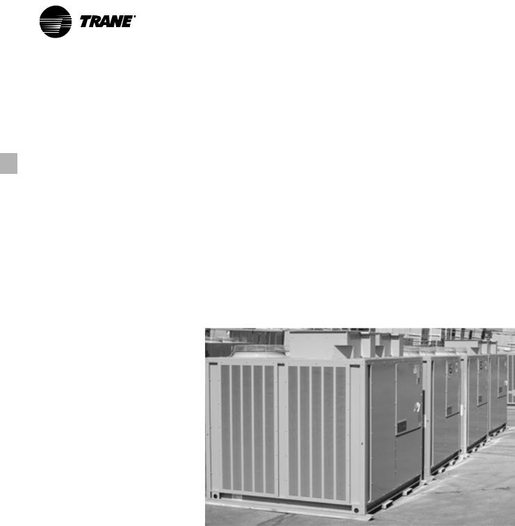
Design and manufacturing excellence makesTrane a leader in the air-cooled chiller marketplace. For over 40 years, Trane has been using the best engineering available in development, manufacturing, and marketing to
produce quality products. This tradition of using excellence to meet market demands is illustrated with theTrane 10 to 60-ton air-cooled chillers.
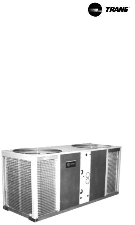
10, 15Tons
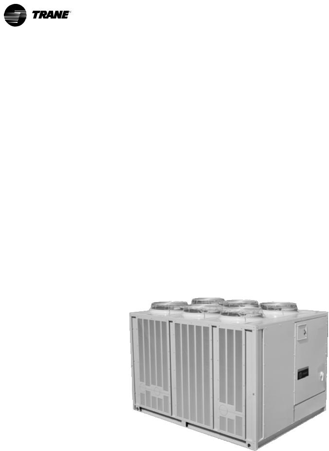
60Tons
© 2003 American Standard Inc. All rights reserved |
CG-PRC007-EN |

Contents
Introduction |
2 |
Features and Benefits |
|
4 |
|
Application Considerations |
|
9 |
|
Selection Procedure |
|
14 |
|
Model Number Description |
|
15 |
|
General Data |
16 |
Performance Data |
|
21 |
|
Performance Adjustment Factors |
|
17 |
|
Controls |
30 |
Electric Power |
|
37 |
|
Dimension andWeights |
|
|
|
39 |
|
Mechanical Specifications |
|
|
|
48 |
|
|
|
CG-PRC001-EN |
3 |
Features and |
(10–60Ton) |
Benefits |
|
|
|
|
|
Installation
Small size, complete factory wiring, easy lifting provisions, factory installed options and start-up control provide fast, easy installation. A complete factory run test is performed on each unit, eliminating potential start-up problems.
Integrated Comfort Systems
AllTrane chillers are ICS compatible. A simple twisted wire pair is all it takes to hook an air-cooled chiller into aTracer system. An ICS system provides the most advanced diagnostics, monitoring, and control that the industry can offer. OnlyTrane can supply the entire package. ICS provides comfort with one word — Trane.
Packed Stock Increases
Project Flexibility
Trane 10 to 60-ton air-cooled chillers are available through the most flexible packed stock program in the industry.
Trane knows you want your units on the jobsite, on time, when you need them. To help meet this demand,Trane keeps a multitude of unit sizes and voltages in packed stock. Many of these include optional features such as isolators, low ambient head pressure controls and refrigerant gauge piping.
You no longer have to settle for a scaled-down, basic unit to meet your job schedule. In many cases, units can be shipped directly to the jobsite from packed stock!
4 |
CG-PRC007-EN |
Features and |
(10–15Ton) |
Benefits |
|
|
|
|
|
The 10 and 15-ton air-cooled Cold Generator™ chillers, withTrane direct drive hermetic scroll compressors, has outstanding standard features and additional benefits that make selection, installation, and servicing easy.
Flexibility
Footprint
Central to the design of any project is the operating envelope of the air-cooled packaged chiller. With this in mind,Trane builds the chillers to make the most efficient use of the available installation space.TheTrane CGA model chillers are extremely compact. They have the lightest weight, the smallest footprint, and the lowest silhouette of any chiller in the industry.
LessWeight
These lightweight models afford less stress on building supports and greater handling ease.
Installation
Installation time and effort are reduced when dealing with a significantly smaller and lighter unit. In addition, having electrical and water connections on the same side of the unit and a single-point main power connection serves to make installation easier. The unit arrives at the jobsite fully assembled, tested, charged and ready to provide chilled water.
Ease of Service
The control panel and unit panels are completely removable for service accessibility and convenience.
ICS Interface
Communication withTraneTracer™ or Tracker™ is possible through the ICS Interface on the 10 and 15 ton Cold Generator chiller.
Optional Features
•Hot Gas Bypass — Allows unit operation below the minimum step of unloading.
•Low Ambient Head Pressure Control
— Modulates the rpm of the fan motor in response to outdoor ambient temperature and unit head pressure. Provides unit cooling operation down to outdoor temperatures of 0°F.
•Coil Guard — Metal grille with PVC coating to protect the condenser coil.
•Isolation — Neoprene in shear or spring flex isolators.
•Power Supply Monitor — Provides protection against phase loss, phase reversal, phase imbalance, incorrect phase sequence and low line voltage.
•ElapsedTime Meter/Number Starts Counter — Records number of compressor starts and operating hours.
•Flow Switch — Required as a safety interlock to prevent operation of unit without evaporator flow (available option for field installation only).
•Integrated Comfort Systems (ICS) Interface — Provides the ability to communicate withTraneTracer or Tracker building management systems via aThermostat Control Module — (TCM).
•Gauges — Monitor suction and discharge pressures.
CG-PRC007-EN |
5 |
Features and |
(20–60Ton) |
Benefits |
|
|
|
|
|
Trane’s 20-60 ton chillers offer the same time-tested and proven control technology that is applied to the IntelliPak Air Cooled rooftops.
Superior control makes the IntelliPak a truly advanced chiller.
Standard Features
Microprocessor Control
The IntelliPak chiller’s Unit Control Module (UCM) is an innovative, modular microprocessor control design. It coordinates the actions of the chiller in an efficient manner and provides stand-alone operation of the unit. A Human Interface (HI) Panel is a standard component of the IntelliPak Chiller. Access to all unit controls is via the Human Interface Panel.
Factory RunTesting
In addition to outstanding efficient performance, IntelliPak Chillers have established a reputation for reliable operation. Aside from the individual component tests, allTrane 20 to 60-ton chillers are factory run tested with water running through the evaporator to confirm proper operation. Control operation and current draw are both monitored to assure safe, reliable operation.
Other Standard Features
•Trane 3-D Scroll compressors
•Advanced motor protection
•300 psi waterside evaporator
•Evaporator insulation (¾-inch Armaflex II or equivalent)
•Evaporator heat tape (thermostat controlled)
•Condenser coil guards
•Operation down to 30°F without additional wind baffles or head pressure control
•Loss of flow protection
•UL and CSA approval available
•Packed stock availability
•Control PowerTransformer
•Low ambient lockout
•Plain English (Spanish/French) Human Interface display
•Smart Lead/Lag operation
•Integrated chilled solution pump control
•Selectable process or comfort control algorithm
•External auto/stop
•Electronic low ambient damper control integrated into UCM
•Flow switch
•Strainer/connection kit
Optional Features
• Controls for ice making operation
Miscellaneous Options
•Trane Communications Interface Module (TCI)
•Unit Mounted Disconnect
•Isolators
•Superheat/Sub-Cooling Module
•Hot Gas Bypass
•Generic B A S Modules with 0-10 v analog input/output, 0-5 v analog input/binary output
•Remote Human Interface Panel (RHI)
•Remote Set point Potentiometer
•Zone Sensor (Chilled Solution Reset)
•Copper Fin Condenser Coils
•Electronic Low Ambient Damper(s)
•Inter-Processor Communication Bridge (IPCB)
•Ice building control
•Other options
In addition to all of these options,Trane can offer in-house design for many applications, including special coil coating.
6 |
CG-PRC007-EN |
Features and |
(20–60Ton) |
Benefits |
|
|
|
|
|
Enhanced Controls
IntelliPak Chiller Unit Control Module (UCM)
Microprocessor Control
The brain of the 20 to 60 ton air-cooled chiller is its Unit Control Module (UCM). The UCM is an innovative, modular microprocessor control design, which coordinates the actions of the chiller in an efficient manner, providing standalone operation of the unit.
Access to the unit controls is via a Human Interface (HI) Panel, a standard component of the IntelliPak chiller. This panel provides a high degree of control. Superior monitoring capability and unmatched diagnostic information is provided through a 2 line 40 character per line, English language display. There are no diagnostic “codes” requiring a translation key for interpretation. All system status information and control adjustments can be made from the onboard Human Interface Panel.
Remote Human Interface (RHI) —The optional Remote Human Interface (RHI) performs the same functions as the Human Interface, with the exception of the service mode. The RHI can be used with up to 4 air-cooled chillers from a single panel.
The Integrated Comfort™ System —The Industry’s MostAdvanced Comfort System
The UCM allows the 20 to 60-ton IntelliPak chiller to be part of the factory installed Integrated Comfort System (ICS). ICS joins theTraneTracer building management systems andTrane HVAC equipment by a single twisted wire pair. This allows bidirectional communication between theTracer system and the unit mounted controls. Connected to the chiller’s UCM, this simple pair allows you to control, monitor, and diagnose your building’s comfort system.The UCM is linked to theTracer system and they electronically “talk” to one another.
Since ICS is factory-packaged, there is no need to install separate sensors to monitor your chiller’s operation. All of the control points are on the controller and ready to go when the unit ships.
Simply hookup theTracer system to the IntelliPakchiller with the twisted wire pair.This feature means lower installed cost, less chance for jobsite errors, less design time on the front end of your project, and fewer callbacks.
ICS gives you the most powerful monitoring and diagnostic system available. Monitoring up to 30 individual points, the ICS can detect and correct problems before a comfort level change is even noticed. Advanced monitoring and diagnostics can help building owners to more effectively market their buildings to prospective tenants.
An ICS system is the most advanced comfort system in the industry. Because Trane has more experience with ICS than all other equipment manufacturers combined, you can feel secure knowing that you are dealing with a proven track record in building management. Trane is the only brand that supplies the entire package.
Tracer control points for IntelliPak Chillers
•Chilled solution set point
•Default chilled solution set point
•Ice set point
•Default ice set point
•Chiller enable point
•Failure mode
•Ice making enable point
•KW limit enable point
•Demand limiting cooling stages
•Default number of compressors
•Design delta temperature
•Control response set point
•Reset option
CG-PRC007-EN |
7 |
Features and |
(20–60Ton) |
Benefits |
|
|
|
|
|
Trane 3-D Scroll Compressor
Simple Design with 70% Fewer Parts
Fewer parts than an equal capacity reciprocating compressor means significant reliability and efficiency benefits.The single orbiting scroll eliminates the need for pistons, connecting rods, wrist pins and valves. Fewer parts lead to increased reliability. Fewer moving parts, less rotating mass and less internal friction means greater efficiency than reciprocating compressors.
TheTrane 3-D Scroll provides important reliability and efficiency benefits.The 3-D Scroll allows the orbiting scrolls to touch in all three dimensions, forming a completely enclosed compression chamber which leads to increased efficiency. In addition, the orbiting scrolls only touch with enough force to create a seal; there is no wear between the scroll plates.The fixed and orbiting scrolls are made of high strength cast iron which results in less thermal distortion, less leakage, and higher efficiencies. The most outstanding feature of the 3-D Scroll compressor is that slugging will not cause failure. In a reciprocating compressor, however, the liquid or dirt can cause serious damage.
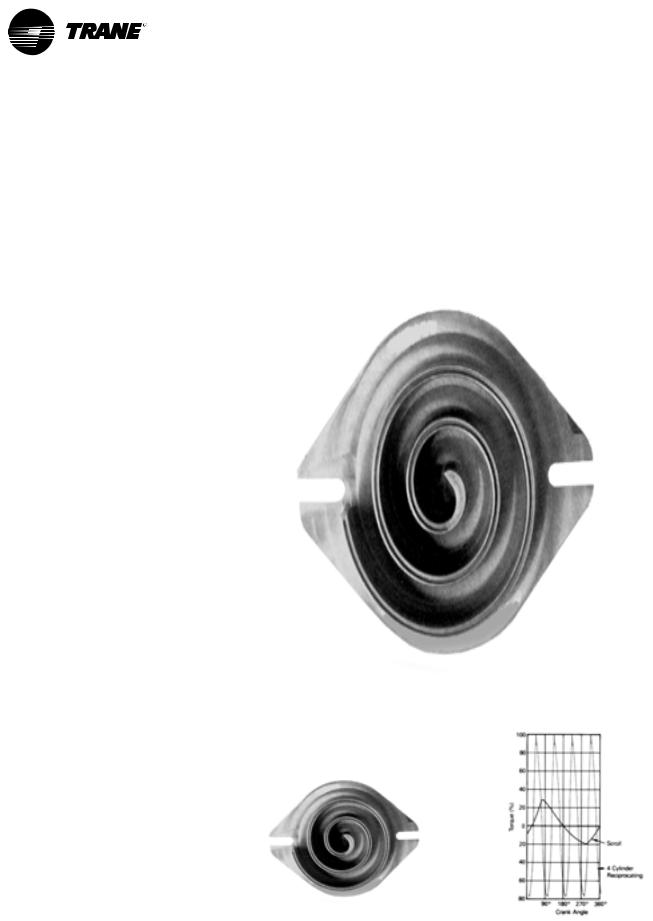
LowTorqueVariation
The 3-D Scroll compressor has a very smooth compression cycle; torque variations are only 30 percent of that produced by a reciprocating compressor. This means that the scroll compressor imposes very little stress on the motor resulting in greater reliability. Low torque variation reduces noise and vibration.
Suction Gas Cooled Motor
Compressor motor efficiency and reliability is further optimized with the latest scroll design. Cool suction gas keeps the motor cooler for longer life and better efficiency.
Proven DesignThroughTesting and
Research
With over twenty years of development and testing,Trane 3-D Scroll compressors have undergone more
One of two matched scroll plates — the distinguishing feature of the scroll compressor.
than 400,000 hours of laboratory testing and field operation.This work combined with over 25 patents makesTrane the worldwide leader in air conditioning scroll compressor technology.
Chart illustrates low torque variation of 3-D Scroll compressor vs. reciprocating compressor.
8 |
CG-PRC007-EN |

Application
Considerations
Certain application constraints should be considered when sizing, selecting and installingTrane air-cooled chillers. Unit and system reliability is often dependent upon proper and complete compliance with these considerations.Where the application varies from the guidelines presented, it should be reviewed with your localTrane sales engineer.
Note: The terms water and solution are used interchangeably in the following paragraphs.
UNIT SIZING
Unit capacities are listed in the “Performance Data” section. Intentionally oversizing a unit to assure adequate capacity is not recommended. Erratic system operation and excessive compressor cycling are often a direct result of an oversized chiller. In addition, an oversized unit is usually more expensive to purchase, install, and operate. If oversizing is desired, consider using two units.
UNIT PLACEMENT
1
SettingThe Unit
A base or foundation is not required if the selected unit location is level and strong enough to support the unit’s operating weight (see “Weights” section of this catalog).
For a detailed discussion of base and foundation construction, refer to the Trane Reciprocating Refrigeration Manual. Manuals are available through the localTrane office.
2
Isolation and Sound Emission
The most effective form of isolation is to locate the unit away from any sound sensitive area. Structurally transmitted sound can be reduced by using spring isolators. Spring isolators are generally effective in reducing vibratory noise generated by compressors, and therefore, are recommended for sound sensitive installations. An acoustical engineer should always be consulted on critical applications.
For maximum isolation effect, water lines and electrical conduit should also be isolated.Wall sleeves and rubber isolated piping hangers can be used to reduce the sound transmitted through water piping. To reduce the sound transmitted through electrical conduit, use flexible electrical conduit.
State and local codes on sound emissions should always be considered. Since the environment in which a sound source is located affects sound pressure, unit placement must be carefully evaluated. Sound pressure and sound power levels for chillers are available on request.
3
Servicing
Adequate clearance for evaporator and compressor servicing should be provided. Recommended minimum space envelopes for servicing are located in the dimensional data section and can serve as a guideline for providing adequate clearance.The minimum space envelopes also allow for control panel door swing and routing maintenance requirements. Local code requirements may take precedence.
4
Unit Location
a
General
Unobstructed flow of condenser air is essential to maintain chiller capacity and operating efficiency.When determining unit placement, careful consideration must be given to assure a sufficient flow of air across the condenser heat transfer surface.Two detrimental conditions are possible and must be avoided: warm air recirculation and coil starvation.
Warm air recirculation occurs when discharge air from the condenser fans is recycled back to the condenser coil inlet. Coil starvation occurs when free airflow to the condenser is restricted.
Condenser coils and fan discharge must be kept free of snow or other obstructions to permit adequate airflow for satisfactory unit operation.
Debris, trash, supplies, etc., should not be allowed to accumulate in the vicinity of the air-cooled chiller. Supply air movement may draw debris into the condenser coil, blocking spaces between coil fins and causing coil starvation.
Both warm air recirculation and coil starvation cause reductions in unit efficiency and capacity because of the higher head pressures associated with them. In addition, in more severe cases, nuisance unit shutdowns will result from excessive head pressures. Estimates of the degree of efficiency and capacity reduction in such situations can be determined. Consult your localTrane sales engineer.
Cross winds, those perpendicular to the condenser, tend to aid efficient operation in warmer ambient conditions, however, they tend to be detrimental to operation in lower ambients or when hot gas bypass is used due to the accompanying loss of adequate head pressure. As a result, it is advisable to protect air-cooled chillers from continuous direct winds exceeding 10 miles per hour in low ambient conditions.
Low Ambient Operation — 20-60Ton models — Human Interface Recommendations
When the temperature outside is subzero, who wants to be out there monitoring or troubleshooting diagnostics? Because we understand a service technician’s reluctance to do this, we recommend using a Remote Human Interface (RHI) panel. The service technician can troubleshoot and diagnose in the comfort of a mechanical room.
CG-PRC007-EN |
9 |
Application
Considerations
b
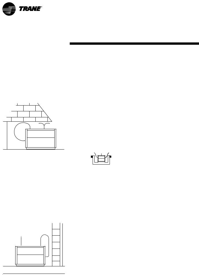
ProvideVertical Clearance
Vertical condenser air discharge must be unobstructed.While it is difficult to predict the degree of warm air recirculation, a unit installed as shown below would have its capacity and efficiency significantly reduced — possibly to the degree of nuisance high head pressure trip outs. Performance data is based on free air discharge.
c
Provide Lateral Clearance
The condenser coil inlet must not be obstructed. A unit installed closer than the minimum recommended distance to a wall or other vertical riser may experience a combination of coil starvation and warm air recirculation, resulting in unit capacity and efficiency reductions and possible excessive head pressures.
The recommended lateral clearances are depicted in the dimensional data section. These are estimates and should be reviewed with the localTrane sales engineer at the jobsite.
d
Provide Sufficient Unit-to-Unit Clearance
Units should be separated from each other by sufficient distance to prevent warm air recirculation or coil starvation. Doubling the recommended single unit air-cooled chiller clearances will generally prove to be adequate.
e
Walled Enclosure Installations
When the unit is placed in an enclosure or small depression, the top of the fans should be no lower than the top of the enclosure or depression. If they are, consideration should be given to ducting the top of the unit. Ducting individual fans, however, is not recommended. Such applications should always be reviewed with the localTrane sales engineer.
VOLTAGE
Nominal voltage is the nameplate rating voltage.The actual range of line voltages at which the equipment can satisfactorily operate are given below.
|
|
Voltage |
Rated |
Utilization |
|
Voltage |
Range |
|
200 |
|
180-220 |
208-230 |
|
187-253 |
230 |
|
208-254 |
380 |
|
342-418 |
400 |
|
360-440 |
415 |
|
374-456 |
460 |
|
414-508 |
575 |
|
520-635 |
WATERTREATMENT
Dirt, scale, products of corrosion, and other foreign material in the water will adversely affect heat transfer between the water and system components.
Foreign matter in the chilled water system can also increase pressure drop and, consequently, reduce waterflow. Proper water treatment must be determined locally and depends on the type of system and local water characteristics.
Do not use salt or brackish water inTrane chillers. Use of either will lead to a shortened life.Trane encourages the employment of a reputable water treatment specialist, familiar with local water conditions, to assist in the establishment of a proper water treatment program.
The capacities given in the “Performance Data” section of this catalog are based on water with a fouling factor of 0.0001 (in accordance with ARI 550/590-98). For capacities at other fouling factors, see “Performance Adjustment Factors” section of this catalog.
EFFECT OFALTITUDE ON CAPACITY
Chiller capacities given in the “Performance Data” section are based upon application at sea level. At elevations substantially above sea level, the decreased air density will decrease condenser capacity and, therefore, unit capacity and efficiency. The adjustment factors in the “Performance Adjustment Factors” section of this catalog can be applied directly to the performance data to determine the unit’s adjusted performance.
10 |
CG-PRC007-EN |
Application
Considerations
AMBIENT LIMITATIONS
Trane chillers are designed for yearround applications in ambients from 0°F to 115°F. For operation below 0°F or above 115°F, contact the localTrane sales office. If hot gas bypass is used, operating ambients vary depending upon unit size (see the “General Data” section of this catalog).
1
LowAmbient Operation
Start-up and operation of Trane chillers at lower ambient temperatures require that sufficient head pressure be maintained for proper expansion valve operation.
Minimum operating ambient temperatures for standard unit selections and units with hot gas bypass are shown in the “General Data” section of this catalog.
Minimum ambient temperatures are based on still conditions (winds not exceeding five mph). Greater wind velocities will result in a drop in head pressure, therefore increasing the minimum starting and operating ambient temperatures.
Optional low ambient units use a electronic low ambient damper control (20-60 tons) or a variable speed fan motor (10-15 tons) arrangement to control condenser capacity by modulating condenser fans in response to refrigerant pressure.
2
HighAmbient Operation
Maximum cataloged ambient temperature operation of a standard Trane chiller is 115°F. Operation at design ambients above 115°F can result in excessive head pressures. For operation above 115°F, contact your localTrane sales office.
CONTROLS
1
Temperature Controller
In order to provide stable system operation and to prevent excessive compressor cycling, the temperature control sensor in all 20-60 ton chillers is located in the supply (outlet) solution. The temperature sensor in all 10 and 15 ton chillers is located in the return (inlet) solution.This sensor cannot be relocated. Doing so would result in improper unit operation.
2 Anti-recycleTimer/Fixed-OffTimer
All IntelliPak air-cooled chillers come standard with Anti-recycle/Fixed Off Timers.This function prevents rapid cycling of the compressors due to low load conditions or short water loops.
3
Pumpdown
CGAF air-cooled chillers will pumpdown, if function is enabled, when a refrigerant circuit is turned off. All of the refrigerant is pumped into the condenser. A solenoid valve provides a positive shut off between the condenser and the evaporator, allowing little or no refrigerant migration to the evaporator during “off” periods.
4
Hot Gas Bypass
Hot gas bypass provides more stable leaving solution temperature control at light load conditions.The compressor runs continuously for a user-defined run time. Minimum starting and operating ambients with hot gas bypass are shown in the “General Data” section of this catalog.The hot gas bypass reduces the unit head pressure, thereby increasing the minimum operating ambient.
5
Loss of Flow Protection
Loss of flow may result in evaporator freeze up. Full chilled solution flow must be maintained through the evaporator while compressors are operating.
A flow switch used as a safety interlock is always recommended for CGA units.
The CGAF air-cooled chiller has a system which senses a loss of flow condition and shuts the unit down. A flow switch used as a safety interlock is required for CGAF units. A set of contacts is available for externally starting and stopping the pump.
WATERFLOW LIMITS
The minimum water flow rates are given in the “General Data” section of this catalog. Evaporator flow rates below the tabulated values will result in laminar flow causing scaling, stratification, freeze-up problems, and poor temperature control.
The maximum evaporator water flow rate is given in the “General Data” section. Flow rates exceeding those listed will result in excessive tube erosion and very high pressure drop across the evaporator.
Trane recommends that constant water flow be maintained at all times through the evaporator. Because the temperature controller strictly senses temperature, variable flow through the evaporator may result in loss of control and localized freezing or nuisance low temperature cutouts. Consult your local Trane sales engineer if your application requires varying flows.
TEMPERATURE LIMITS
1
Leaving SolutionTemperature range
The minimum leaving solution temperature set point is dependent on the number of capacity stages and the temperature difference across the evaporator.Water supply temperature set points less than these values result in suction temperatures at or below the freezing point of cold water.
A glycol solution is required for operation below the recommended minimum set points. Refer to the “Performance Adjustment Factors” section of this catalog to determine the minimum leaving chilled solution set
CG-PRC007-EN |
11 |

Application
Considerations
point and adequate ethylene glycol concentration for safe operation.
The maximum catalog leaving solution temperature from the evaporator is 65°F for outdoor ambients up to 115°F. High leaving water temperatures exceeding this may result in excessive suction temperatures and, therefore, inadequate motor cooling. For applications requiring high leaving water temperatures, contact your localTrane sales office for suggested alternatives.
The maximum water temperature that can be circulated through an evaporator, when the unit is not operating, is 108°F (100°F for CGA 8, 10, 12½ and 15 ton chillers). The evaporator becomes thermal stress limited at these temperatures.
2
SupplyWaterTemperature Drop
The performance data forTrane chillers is based on a chilled water temperature drop of 10°F.Temperature drops outside this range will result in unit performance that differs from that cataloged. For performance data outside the 10°F range see the “Performance Adjustment Factors” section in this catalog. Chilled water temperature drops from 6 to 18°F (8 to 12°F in CGA units) may be used as long as minimum and maximum water temperature and minimum and maximum flow rates are not violated.
Temperature drops outside 6 to 18°F (8 to 12°F in CGA units) are beyond the optimum range for control and may adversely affect the controller’s capability to maintain an acceptable supply water temperature range.
Further, temperature drops of less than 6°F may result in inadequate refrigerant superheat. Sufficient superheat is always a primary concern in any direct expansion refrigeration system and is especially important in a package chiller where the evaporator is closely coupled to the compressor.When temperature drops are less than 6°F, an evaporator runaround loop may be required.
TYPICALWATER PIPING
All building water piping must be flushed prior to making final connections to the chiller.To reduce heat loss and prevent condensation, insulation should be applied. Expansion tanks are also usually required so that chilled water volume changes can be accommodated. A typical piping arrangement is shown on the following page.
WATERVOLUME IN THE LOOP (MINIMUM LOOPTIME)
The volume of water in the loop is critical to the stability of system operation.The minimum required water volume is dependant on the chiller controller and system GPM.Water volumes less than the minimum required for the system can cause nuisance problems including low pressure trips and freezestat trips. The cause of these trips is “ShortWater Loops”.
The minimum required water volume (as a function of loop time and GPM) is as follows:
CGAF: Minimum LoopVolume = GPM
x 3 Minute LoopTime
CGA: Minimum LoopVolume = GPM
X 5 Minute LoopTime
If the loop piping does not contain enough volume, then a tank should be added so that the equations hold true. Generally, the more the loop volume the greater the system stability and controllability.
EXAMPLE: CGAFC50 with 100 gpm.
Minimum LoopVolume =
GPM x 3 Minute LoopTime Minimum LoopVolume = 100 x 3
300 Gallon Minimum LoopVolume
If a chiller is attached to an on/off load such as a process load, it may be difficult for the controller to respond quickly enough to the very rapid change in return solution temperature.This condition may result in freezestat or low temperature trips. In this case, it may be necessary to add a mixing tank in the return line.
MULTIPLE UNIT OPERATION
Whenever two or more units are used on one chilled water loop,Trane recommends that their operation be controlled from a single control device, such as aTraneTracer system.The “Stand-alone” alternative is the DDC Chiller Sequencer.
1
Series Operation
Some systems require large chilled water temperature drops (16 to 24°F). For those installations, two units with their evaporators in series are usually required. Control of the units should be from a common temperature sensor to prevent the separate unit controls from fighting one another and continually hunting. It is possible to control water temperature from the two individual unit controls, but a common temperature controller provides a positive method for preventing control overlap, more closely matching system load and simplifying compressor lead-lag capability.
2
Parallel Operation
Some systems require more capacity or standby capability than a single machine can provide. For those installations, two units with their evaporators in a parallel configuration are typical.The only effective way of controlling two units in parallel is with a single temperature controller. For further information, please contactTrane Applications.
12 |
CG-PRC007-EN |

Application
Considerations
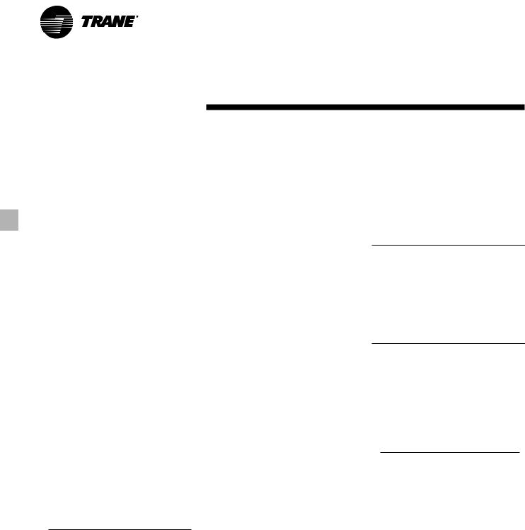
10, 15Ton |
Figure AC-1 — Recommended Piping Components ForTypical Evaporator Installation |
Note: Provide shutoff valves in the evaporator inlet and outlet to facilitate water temperature sensor removal.
20–60Ton
See unit dimensional drawings for inlet and outlet locations.
CG-PRC007-EN |
13 |
Selection
Procedure
The chiller capacity tables presented in the “Performance Data” section cover the most frequently encountered leaving water temperatures.The tables reflect a 10°F temperature drop through the evaporator. For temperature drops other than 10°F, fouling factors other than 0.0001 (in accordance with ARI Standard 550/590-98) and for units operating at altitudes that are significantly greater than sea level, refer to the “Performance Adjustment Factors” section and apply the appropriate adjustment factors. For chilled brine selections, refer to the “Performance Adjustment Factors” section for ethylene glycol adjustment factors.
To select aTrane air-cooled chiller, the following information is required:
1
Design system load (in tons of refrigeration).
2
Design leaving chilled water temperature.
3
Design chilled water temperature drop.
4
Design ambient temperature.
5
Evaporator fouling factor.
Evaporator chilled water flow rate can be determined by using the following formula:
Tons x 24
GPM = Temperature Drop (Degrees F)
NOTE: Flow rate must fall within the limits specified in the “General Data” section of this catalog.
SELECTION EXAMPLE
Given:
Required System Load = 53 tons
Leaving ChilledWaterTemperature (LCWT) = 45°F
ChilledWaterTemperature Drop = 10°F
Design AmbientTemperature = 95°F
Evaporator Fouling Factor = 0.0001
1
To calculate the required chilled waterflow rate we use the formula:
GPM = Tons x 24
∆T
From the 60 ton unit table in the “Performance Data” section of this catalog, a CGAF-C60 at the given conditions will produce 57.3 tons with a system power input of 70.2 kw and a unit EER of 9.8
GPM = 56.8 Tons x 24 = 137.5
10°F
2
To determine the evaporator water pressure drop we use the flow rate (gpm) and the evaporator water pressure drop curves found in the “Performance Adjustment Factors” section of this catalog. Entering the curve at 137.5 gpm, the pressure drop for a nominal 60 ton evaporator is 16.5 feet.
3
For selection of chilled brine units or applications where the altitude is significantly greater than sea level or the temperature drop is different than 10°F, the performance adjustment factors should be applied at this point.
For example:
Corrected Capacity = Capacity
(unadjusted) x Appropriate Adjustment
Factor
Corrected Flow Rate = Flow Rate
(unadjusted) x Appropriate Adjustment
Factor
Corrected KW Input = KW Input
(unadjusted) x Appropriate Adjustment
Factor
4
Verify that the selection is within design guidelines.The final unit selection is:
Quantity (1) CGAF-C60
Cooling Capacity = 57.3Tons
Entering/Leaving ChilledWater
Temperatures = 55/45°F
ChilledWaterflow Rate (GPM) = 137.5
EvaporatorWater Pressure Drop = 16.5 ft.
System Power Input = 70.2 KW
Unit EER = 9.8
MINIMUM LEAVING CHILLEDWATER TEMPERATURE SET POINTS
The minimum leaving chilled water temperature set point for water is listed in the following table:
Table SP-1 — Minimum Leaving Chilled WaterTemperature Set points forWater1
Evaporator |
Minimum Leaving Chilled Water |
|
Temperature |
Temperature Set point (°F) |
|
Difference |
CGAF- |
CGAF- |
(Degrees F) |
C20,C25,C30 |
C40,C50,C60 |
6 |
40 |
39 |
8 |
41 |
39 |
10 |
42 |
40 |
12 |
43 |
40 |
14 |
44 |
41 |
16 |
45 |
41 |
18 |
46 |
42 |
1These are for units without HGBP, for units with HGBP, add 2°F to each minimum temperature in the table.
For those applications requiring lower set points, a glycol solution must be used. The minimum leaving chilled water set point for a glycol solution can be calculated using the following equation:
LCWS (Minimum) = GFT + 5 + ∆T (Evap)
# of stages of capacity.
LCWS = |
Leaving ChilledWater |
|
|
|
Set point (F) |
GFT |
= |
Glycol Freezing |
∆T |
|
Temperature (F) |
= |
DeltaT (the difference |
|
between the temperature of the water entering and leaving the evaporator)
Solution freezing point temperatures can be found in the Performance Data section and the number of stages of capacity in the General Data section. For selection assistance, refer to the CGA Chiller Selection program.
14 |
CG-PRC007-EN |
Model
Number
Description
DIGIT 1,2,3 — UnitType
CGA = Air-Cooled Cold Generator™
DIGITS 4,5,6 — Nominal Capacity (MBh)
100 |
= 8 Tons (50 Hz Model only) |
|
120 |
= 10 Tons (60 Hz Model only) |
|
150 |
= |
12.5 Tons (50 Hz Model Only) |
180 |
= |
15 Tons (60 Hz Model Only) |
DIGIT 7 — Major Design Change
(Number of Refrigerant Circuits/Number of
Compressors)
B = 2 Refrigerant Circuits/2 Compressors
10, 15Tons
|
CGA |
120 |
B |
3 |
00 |
B A |
|
|
|
123 |
456 |
7 |
8 |
9,10 |
11 12 |
|
|
DIGIT 8 —Voltage |
|
|
|
|
DIGIT 10 — Leaving Solution Set point |
|
||
1 |
= 208-230/60/1 |
|
|
|
0 =Standard Expansion Valve |
|
||
|
(Available — CGA120 Only) |
|
40-60°F Leaving Water |
|
||||
3 |
= 208-230/60/3 |
|
|
|
(CGA100 & CGA120 models) |
|
||
4 |
= 460/60/3 |
|
|
|
|
20-60°F Leaving Solution |
|
|
W = 575/60/3 |
|
|
|
|
(CGA150 & CGA180 Models) |
|
||
|
|
|
|
|
||||
D = 380-415/50/3 |
|
|
|
V = Nonstandard Expansion Valve |
|
|||
|
|
|
|
|||||
|
|
|
|
|
|
|
20-39°F Leaving Solution |
|
DIGIT 9 — Factory Installed Options |
(CGA100 & CGA120 models) |
|
||||||
0 |
= No Options |
|
|
|
|
DIGIT 11 — Minor Design Change |
|
|
H = Hot Gas Bypass |
|
|
|
|
||||
|
|
|
A = First, B = Second, etc. |
|
||||
C = Black Epoxy Coil Standard Deviation |
|
|||||||
K = Hot Gas Bypass & Black Epoxy Coil |
|
|
||||||
S = Special |
|
|
|
|
DIGIT 12 —Service Digit |
|
||
CG A F C40 4
12 3 4 567 8
DIGIT 1,2 — Unit Model
CG = IntelliPak™ Air-Cooled Chiller
DIGIT 3 — UnitType
A = Air-Cooled Condensing
DIGIT 4 — Development Sequence
A, B, C, etc.
DIGIT 5,6,7 — Nominal Capacity
C20 = 20 Tons
C25 = 25 Tons
C30 = 30 Tons
C40 = 40 Tons
C50 = 50 Tons
C60 = 60 Tons
DIGIT 8 —Voltage & Start Characteristics
E = 200/60/3 XL F = 230/60/3 XL 4 = 460/60/3 XL 5 = 575/60/3 XL 9 = 380/50/3 XL D = 415/50/3 XL S = Special
DIGIT 9 — Factory Input
A = Standard
1.The service digit for each model number contains 25 digits; all 25 digits must be referenced.
CG-PRC007-EN
20–60Tons
A |
|
A A 1 A A A A A 0 0 0 0 0 0 0 01 |
|||||||||||||||
|
|
|
|
|
|
|
|
|
|
|
|
|
|
|
|
|
|
9 |
|
10 |
11 12 |
13 |
14 |
15 |
16 |
17 |
18 19 |
20 21 |
22 23 24 |
25 |
|||||
DIGIT 10 — Design Sequence
A = First
B = Second
Etc...
DIGIT 11 — Leaving Solution Set point
A= 40-50 Deg. F w/o Ice Machine
B= 30-39 Deg. F w/o Ice Machine
D= 51-65 Deg. F w/o Ice Machine
E= 20-29 Deg. F w/o Ice Machine 1 = 40-50 Deg. F with Ice Machine 2 = 30-39 Deg. F with Ice Machine 3 = 51-65 Deg. F with Ice Machine 4 = 20-29 Deg. F with Ice Machine
S= Special
DIGIT 12 —AgencyApproval
1 = UL/CSA
0 = None
DIGITS 13-25 — Miscellaneous
A = Trane Communication Interface
(TCI) Module
B= No Unit Heat Tape (50 Hz Only)
C= Compressor Current Sensing (CSM)
D= Unit Mounted Disconnect Switch Nonfused
E= Unit Isolators Neoprene
F= Unit Isolators Spring
G= Superheat/Sub-Cooling
H= Hot Gas Bypass
J = Generic B A S Module (0-5 v Input, Binary Output)
M = Remote Human Interface
N= Generic B A S Module (0-10 v Analog)
P= Remote Set point Potentiometer
Q= Zone Sensor — Chilled Solution Reset
V= Copper Fin Condenser Coils
W= Electronic Low Ambient Damper(s)
Y= Inter-Processor Communication Bridge (IPCB)
9 = Packed Stock Unit
The following items can be ordered for separate shipment —
•Unit Isolators — Neoprene*
•Unit Isolators — Spring*
•Electronic Low Ambient Damper(s)
•Trane Communication Interface Module (TCI)
•Generic B A S Module (GBAS)
•(0-5 volt Analog Input/Binary Output)
•Generic B A S Module (GBAS)
•(0-10 volt Analog Input/Output)
•Remote Human Interface
•Remote Set point Potentiometer
•Zone Sensor (Chilled Solution Reset)
•Inter-Processor Communication Bridge
(IPCB)
*Unit size must be specified when ordering this item.
15
General Data
Table GD-1 — General Data — 10–60Ton Units
|
10Ton |
15Ton |
20Ton |
25Ton |
30Ton |
40Ton |
50Ton |
60Ton |
Model Number |
CGA120 |
CGA180 |
CGAF-C20 |
CGAF-C25 |
CGAF-C30 |
CGAF-C40 |
CGAF-C50 |
CGAF-C60 |
Compressor Data |
|
|
|
|
|
|
|
|
Model |
Scroll |
Scroll |
Scroll |
Scroll |
Scroll |
Scroll |
Scroll |
Scroll |
Quantity |
2 |
2 |
2 |
1/1 |
2 |
4 |
2/2 |
4 |
Nominal Tons per Compressor |
5 |
7.5 |
10 |
10/15 |
15 |
10 |
10/15 |
15 |
Evaporator |
|
|
|
|
|
|
|
|
Nominal Size (Tons) |
10 |
15 |
20 |
25 |
30 |
40 |
50 |
60 |
Water Storage Capacity (Gallons)² |
1.4 |
1.5 |
2.2 |
2.7 |
3.2 |
4.1 |
5.0 |
7.4 |
Min. Flow Rate (GPM) |
12.0 |
18.0 |
24 |
30 |
36 |
48 |
60 |
72 |
Max. Flow Rate (GPM) |
36.0 |
54.0 |
72 |
90 |
108 |
144 |
180 |
216 |
Max EWT At Start-Up — Deg F³ |
100 |
100 |
108 |
108 |
108 |
108 |
108 |
108 |
Condenser |
|
|
|
|
|
|
|
|
Nominal Size (Tons) |
10 |
15 |
20 |
25 |
30 |
40 |
50 |
60 |
Number of Coils |
1 |
2 |
1 |
2 |
2 |
2 |
2 |
2 |
Coil Size (ea., Inches)4 |
28 x 108 |
28 x 83 |
61 x 71 |
45 x 71/35 x 71 |
56 x 70 |
56 x 70 |
57 x 96 |
57 x 96 |
Number of Rows |
2 |
2 |
3 |
3 |
3 |
3 |
3 |
4 |
Subcooler Size (ea., Inches) |
4 x 10⁸ |
4 x 83 |
10 x 71 |
14 x 71 |
9 x 70 |
9 x 70 |
9 x 96 |
9 x 96 |
Condenser Fans |
|
|
|
|
|
|
|
|
Quantity |
1 |
2 |
2 |
3 |
4 |
4 |
6 |
6 |
Diameter (Inches) |
28 |
26 |
26 |
26 |
26 |
26 |
26 |
26 |
CFM (Total) |
8,120 |
11,600 |
15,000 |
21,650 |
29,200 |
29,200 |
42,300 |
40,700 |
Nominal RPM |
1100 |
1100 |
1140 |
1140 |
1140 |
1140 |
1140 |
1140 |
Tip Speed (Ft/Min) |
8060 |
7490 |
7750 |
7750 |
7750 |
7750 |
7750 |
7750 |
Motor HP (ea.) |
1.0 |
1/2 |
1.0 |
1.0 |
1.0 |
1.0 |
1.0 |
1.0 |
Drive Type |
Direct |
Direct |
Direct |
Direct |
Direct |
Direct |
Direct |
Direct |
Minimum Outdoor Air Temperature Permissible |
|
|
|
|
|
|
|
|
For Mechanical Cooling¹ |
|
|
|
|
|
|
|
|
Standard Ambient Control Unit (°F) |
50 |
50 |
30 |
30 |
30 |
30 |
30 |
30 |
Standard Ambient w/Hot Gas Bypass (°F) |
60 |
60 |
40 |
40 |
40 |
40 |
40 |
40 |
Low Ambient Option (°F) |
0 |
0 |
0 |
0 |
0 |
0 |
0 |
0 |
Low Ambient Control w/Hot Gas Bypass(°F) 15 |
15 |
10 |
10 |
10 |
10 |
10 |
10 |
|
General Unit |
|
|
|
|
|
|
|
|
Unload Steps |
100-50 |
100-50 |
100-50 |
100-60-40 |
100-50 |
100-75-50-25 100-80-60-30100-75-50-25 |
||
No. of Independent Refrig. Circuits |
2 |
2 |
1 |
1 |
1 |
2 |
2 |
2 |
Refrigerant Charge (lbs. R22/Circuit) |
8.25 |
11.5 |
40.5 |
54.0 |
72.0 |
38.0 |
49.0 |
75.00 |
Oil Charge (Pints/Circuit) |
4.1 |
7.5 |
17.0 |
22.3 |
27.6 |
17.0 |
22.3 |
27.6 |
*Unloading steps depend upon which compressor is lead compressor. Notes:
1.Minimum start-up ambient based on unit at minimum step of unloading and a 5 mph wind across the condenser.
2.Includes piping internal to chiller.
3.At 95°F ambient.
4.Does not include subcooling portion of coil.
16 |
CG-PRC007-EN |
 Loading...