


RAUJ
Table of contents
 Loading...
SAFETY WARNING
Only qualified personnel should install and service the equipment. The installation, starting up, and
servicing of heating, ventilating, and air-conditioning equipment can be hazardous and requires specific
knowledge and training. Improperly installed, adjusted or altered equipment by an unqualified person could
result in death or serious injury. When working on the equipment, observe all precautions in the literature
and on the tags, stickers, and labels that are attached to the equipment.
Tube Size and Component Selection
RAUJ Split Systems (20-120 Tons)
R-410A Refrigerant
Fin and Tube Condensers
March 2012 SS-APG007-EN
Application Guide

SS-APG007-EN © 2012 Trane All rights reserved
Warnings, Cautions and Notices
Warnings, Cautions and Notices. Note that warnings, cautions and notices appear at
appropriate intervals throughout this manual. Warnings are provided to alert installing contractors
to potential hazards that could result in death or personal injury. Cautions are designed to alert
personnel to hazardous situations that could result in personal injury, while notices indicate a
situation that could result in equipment or property-damage-only accidents.
Your personal safety and the proper operation of this machine depend upon the strict observance
of these precautions.
Read this manual thoroughly before operating or servicing this unit.
Important
Environmental Concerns!
Scientific research has shown that certain man-made chemicals can affect the earth’s naturally
occurring stratospheric ozone layer when released to the atmosphere. In particular, several of the
identified chemicals that may affect the ozone layer are refrigerants that contain Chlorine, Fluorine
and Carbon (CFCs) and those containing Hydrogen, Chlorine, Fluorine and Carbon (HCFCs). Not all
refrigerants containing these compounds have the same potential impact to the environment.
Trane advocates the responsible handling of all refrigerants—including industry replacements for
CFCs such as HCFCs and HFCs.
Responsible Refrigerant Practices!
Trane believes that responsible refrigerant practices are important to the environment, our
customers, and the air conditioning industry. All technicians who handle refrigerants must be
certified. The Federal Clean Air Act (Section 608) sets forth the requirements for handling,
reclaiming, recovering and recycling of certain refrigerants and the equipment that is used in these
service procedures. In addition, some states or municipalities may have additional requirements
that must also be adhered to for responsible management of refrigerants. Know the applicable
laws and follow them.
ATTENTION: Warnings, Cautions and Notices appear at appropriate sections throughout this
literature. Read these carefully:
WARNING
Indicates a potentially hazardous situation which, if not avoided, could result in
death or serious injury.
CAUTIONs
Indicates a potentially hazardous situation which, if not avoided, could result in
minor or moderate injury. It could also be used to alert against unsafe practices.
NOTICE:
Indicates a situation that could result in equipment or property-damage only
accidents.
WARNI NG
Proper Field Wiring and Grounding Required!
All field wiring MUST be performed by qualified personnel. Improperly installed and grounded
field wiring poses FIRE and ELECTROCUTION hazards. To avoid these hazards, you MUST
follow requirements for field wiring installation and grounding as described in NEC and your
local/state electrical codes. Failure to follow code could result in death or serious injury.
ii SS-APG007-EN
Warnings, Cautions and Notices
Trademarks
Trane, Frostat and the Trane logo are trademarks of Trane in the United States and other countries.
All trademarks referenced in this document are the trademarks of their respective owners.
WARNI NG
Personal Protective Equipment (PPE) Required!
Installing/servicing this unit could result in exposure to electrical, mechanical and chemical
hazards.
• Before installing/servicing this unit, technicians MUST put on all Personal Protective
Equipment (PPE) recommended for the work being undertaken. ALWAYS refer to appropriate
MSDS sheets and OSHA guidelines for proper PPE.
• When working with or around hazardous chemicals, ALWAYS refer to the appropriate MSDS
sheets and OSHA guidelines for information on allowable personal exposure levels, proper
respiratory protection and handling recommendations.
• If there is a risk of arc or flash, technicians MUST put on all Personal Protective Equipment
(PPE) in accordance with NFPA 70E or other country-specific requirements for arc flash
protection, PRIOR to servicing the unit.
Failure to follow recommendations could result in death or serious injury.
WARNI NG
R-410A Refrigerant under Higher Pressure than R-22!
The units described in this manual use R-410A refrigerant which operates at higher pressures
than R-22 refrigerant. Use ONLY R-410A rated service equipment or components with these
units. For specific handling concerns with R-410A, please contact your local Trane
representative.
Failure to use R-410A rated service equipment or components could result in equipment
exploding under R-410A high pressures which could result in death, serious injury, or
equipment damage.

Table of Contents
SS-APG007-EN iii
Overview . . . . . . . . . . . . . . . . . . . . . . . . . . . . . . . . . . . . . . . . . . . . . . . . . . . . . . . . . . . . . . 1
Background . . . . . . . . . . . . . . . . . . . . . . . . . . . . . . . . . . . . . . . . . . . . . . . . . . . . . . . 1
Updated Guidelines . . . . . . . . . . . . . . . . . . . . . . . . . . . . . . . . . . . . . . . . . . . . . . . . 2
Liquid Lines . . . . . . . . . . . . . . . . . . . . . . . . . . . . . . . . . . . . . . . . . . . . . . . . . . 2
Suction Lines . . . . . . . . . . . . . . . . . . . . . . . . . . . . . . . . . . . . . . . . . . . . . . . . . 2
Equipment Placement . . . . . . . . . . . . . . . . . . . . . . . . . . . . . . . . . . . . . . . . . . 3
Line Sizing, Routing, and Component Selection . . . . . . . . . . . . . . . . . . . . . . . . . . . 4
Liquid Lines . . . . . . . . . . . . . . . . . . . . . . . . . . . . . . . . . . . . . . . . . . . . . . . . . . . . . . . 4
Line Sizing . . . . . . . . . . . . . . . . . . . . . . . . . . . . . . . . . . . . . . . . . . . . . . . . . . . 4
Routing . . . . . . . . . . . . . . . . . . . . . . . . . . . . . . . . . . . . . . . . . . . . . . . . . . . . . . 4
Insulation . . . . . . . . . . . . . . . . . . . . . . . . . . . . . . . . . . . . . . . . . . . . . . . . . . . . 5
Components . . . . . . . . . . . . . . . . . . . . . . . . . . . . . . . . . . . . . . . . . . . . . . . . . 5
Suction Lines . . . . . . . . . . . . . . . . . . . . . . . . . . . . . . . . . . . . . . . . . . . . . . . . . . . . . . 6
Line Sizing . . . . . . . . . . . . . . . . . . . . . . . . . . . . . . . . . . . . . . . . . . . . . . . . . . . 6
Routing . . . . . . . . . . . . . . . . . . . . . . . . . . . . . . . . . . . . . . . . . . . . . . . . . . . . . . 6
Insulation . . . . . . . . . . . . . . . . . . . . . . . . . . . . . . . . . . . . . . . . . . . . . . . . . . . . 6
Components . . . . . . . . . . . . . . . . . . . . . . . . . . . . . . . . . . . . . . . . . . . . . . . . . 7
Expansion Valves . . . . . . . . . . . . . . . . . . . . . . . . . . . . . . . . . . . . . . . . . . . . . . . . . . . . . . . 8
Controls . . . . . . . . . . . . . . . . . . . . . . . . . . . . . . . . . . . . . . . . . . . . . . . . . . . . . . . . . . . . . . . 9
Hot Gas Bypass . . . . . . . . . . . . . . . . . . . . . . . . . . . . . . . . . . . . . . . . . . . . . . . . . . . . . . . 10
Remodel, Retrofit, or Replacement . . . . . . . . . . . . . . . . . . . . . . . . . . . . . . . . . . . . . . 11
Examples of Field-Installed Evaporator Piping . . . . . . . . . . . . . . . . . . . . . . . . . . . . 13
Single-Circuit RAUJs . . . . . . . . . . . . . . . . . . . . . . . . . . . . . . . . . . . . . . . . . . . . . . 13
Dual-Circuit RAUJs . . . . . . . . . . . . . . . . . . . . . . . . . . . . . . . . . . . . . . . . . . . . . . . . 15
Parts . . . . . . . . . . . . . . . . . . . . . . . . . . . . . . . . . . . . . . . . . . . . . . . . . . . . . . . . . . . . . . . . . 18

iv SS-APG007-EN
SS-APG007-EN 1
Overview
Trane’s RAUJ 20- through 120-ton condensing unit product line incorporating fin and tube
condenser coils has been designed for use only with R-410A and POE oil. R-410A is a high-pressure
refrigerant that requires the other components of the system, including the evaporator, to be rated
for R-410A pressures. For compressor lubrication, the refrigerant requires POE oil.
Traditionally, refrigerant piping practices were guided by four principles:
• Return the oil to the compressor.
• Maintain a column of liquid at the expansion valve.
• Minimize the loss of capacity.
• Minimize the refrigerant charge in the system.
These piping practices are similar for R-410A and POE oil. However, because of the different mass
flows and pressures, the line diameter required to carry the oil and refrigerant may not be the same
as a similar tonnage R-22 unit. Also, the allowable pressure drop may be greater for R-410A than
R-22.
Evidence accumulated over years of observation demonstrates that the lower the refrigerant
charge, the more reliably a split air-conditioning system performs. Any amount of refrigerant in
excess of the minimum design charge becomes difficult to manage. The excess refrigerant tends
to collect in areas that can interfere with proper operation and eventually shortens the service life
of the system.
To successfully minimize the system refrigerant charge, the correct line size should be used and
the line length must be kept to a minimum.
Background
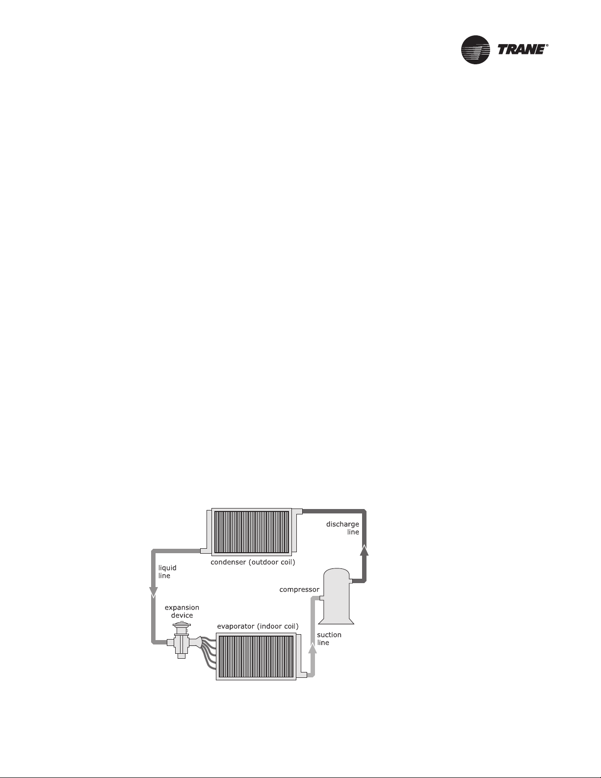
In a split air-conditioning system, the four major components of the refrigeration system are
connected by field-assembled refrigerant piping (Figure 1). A suction line connects the
evaporator to the compressor, the discharge line connects the compressor to the condenser, and
the liquid line connects the condenser to the expansion device, which is located near the
evaporator inlet. Operational problems can occur if these refrigerant lines are designed or
installed improperly.
.
Figure 1. Interconnecting refrigerant lines in a typical split air-conditioning system
2 SS-APG007-EN
Overview
The origin of the requirements for equivalent line lengths of components, line pressure drop, and
minimum and maximum refrigerant velocities is uncertain. It appears likely that at least some of
the supporting data was derived from measurements and/or equations involving water. Some
resource materials even show water components when illustrating refrigerant piping
requirements.
Subsequent reviews of analytical and empirical data for refrigerant piping resulted in the
publication of two research papers: Pressure Losses in Tubing, Pipe, and Fittings by R.J.S. Pigott
and Refrigerant Piping Systems — Refrigerants 12, 22, 500 by the American Society of
Refrigeration Engineers (ASRE). In his paper, Pigott described his use of refrigerant as the fluid
and his direct measurement of pressure drops. His findings indicated that the pressure drop of
many line components is small and difficult to measure. For these components, he used
experimental data to derive a formula relating the geometry of the component to its pressure
drop. Overall, his calculated pressure loss of the components was less than originally
determined.
The conclusion of the ASRE research paper stated that the minimum required velocity to
maintain oil entrainment in vertical risers and horizontal lines will vary with the diameter of the
tube and with the saturation temperature of the suction gas. In other words, the minimum
required velocity for oil entrainment is not constant.
Updated Guidelines
Liquid Lines
Historically, liquid lines were sized to minimize the pressure losses within the piping circuit. Oil
movement through the piping wasn’t a concern (nor is it today) because oil is miscible in liquid
refrigerant at normal liquid-line temperatures. The historic and traditional 6 psid liquid line
pressure drop had the unintended consequence of requiring line sizes with large internal
refrigerant volumes. Since our objective is also to minimize the refrigerant charge to make the
most reliable systems, we increased the allowable liquid pressure drop to 35 psid (R-22), which
allows for the selection of a smaller liquid line while still maintaining refrigeration operation.
With R-410A refrigerant and POE oil, this pressure drop can be as high as 50 psid. Within these
guidelines, refrigeration operation is maintained while minimizing the refrigerant charge. It is
still required to limit the liquid line velocity to 600 ft/min to help avoid issues with water hammer.
Suction Lines
R-410A is a high-pressure refrigerant and allows higher-pressure drops in the suction lines. With
R-22, a 2°F loss in the suction line means a pressure drop of 3 psi. With R-410A refrigerant, that
same 2°F loss is a 5 psi drop. Additional pressure drop may be tolerated in certain applications.
R-410A refrigerant suction lines must be sized to maintain oil-entrainment velocities in both the
horizontal and vertical risers. Oil entrainment for R-410A is based on suction temperature as well
as tube diameter. At the time of this writing, no known direct oil-entrainment tests have been
conducted. Trane has used ASHRAE data to create equation-based formulas to predict the
entrainment velocities of R-410A refrigerant and POE oil. These minimum velocities are reflected
in the line sizes listed in the component selection summary (Table 2, p. 18).
SS-APG007-EN 3
Overview
Equipment Placement
Minimize Distance Between Components
For a split air-conditioning system to perform as reliably and inexpensively as possible, the
refrigerant charge must be kept to a minimum. To help accomplish this design goal:
• Site the outdoor unit as close to the indoor unit as possible.
• Route each interconnecting refrigerant line by the shortest and most direct path so that line
lengths and riser heights are no longer than absolutely necessary.
• Use only horizontal and vertical piping configurations.
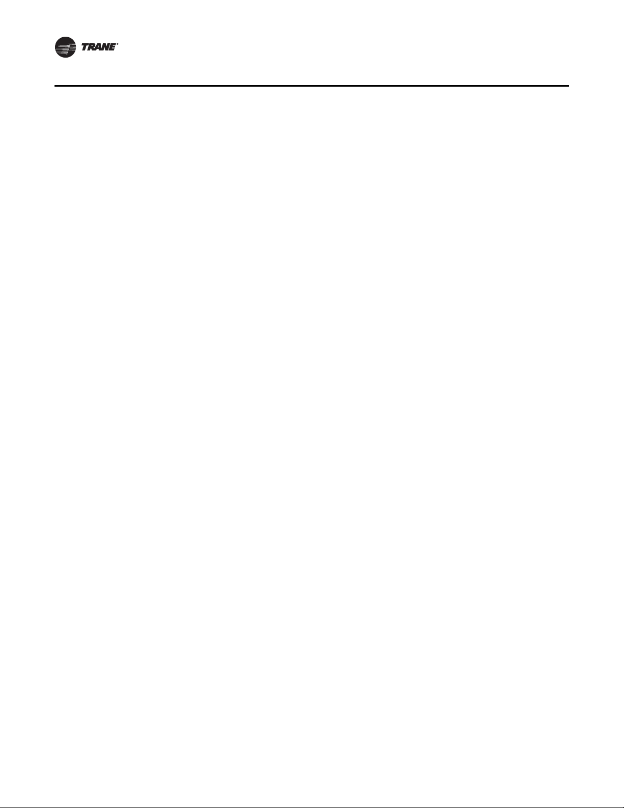
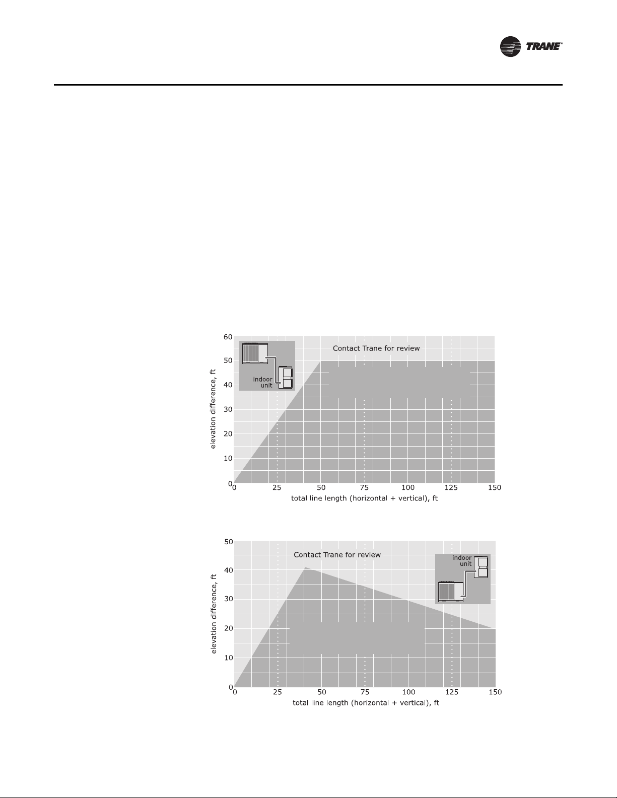
• Determine whether the total length of each refrigerant line requires Trane review. Be sure to
account for the difference in elevations of the indoor and outdoor units when calculating the
total line length.
Interconnecting lines of 150 lineal ft (45.7 m) or less do not require Trane review, but only a
limited amount may be in a riser (see Figure 2 and Figure 3).
.
RAUJ
Acceptable suction-riser height
based on total suction-line length
(RAUJ above indoor unit)
Figure 2. Allowable elevation difference: Cooling-only RAUJ above indoor unit
RAUJ
Acceptable liquid-riser height
based on total liquid-line length
(RAUJ below indoor unit)
Figure 3. Allowable elevation difference: Cooling-only RAUJ below indoor unit
Loading...