


Trane RTAA-70, RTAA-80, RTAA-90, RTAA-100, RTAA-110 Installation Manual
...Installation
Operation
Maintenance
Series R®
Air-Cooled Rotary Liquid Chillers
Packaged Air-Cooled Chiller,
RTAA 70-125
Remote Evaporator
Air-Cooled Chiller,
RTAA 70-125
Models RTAA |
|
RTAA-70 |
RTAA-100 |
RTAA-80 |
RTAA-110 |
RTAA-90 |
RTAA-125 |
|
|
|
|
September 2005 |
RTAA-SVX01A-EN |
© American Standard Inc. 2005
NOTICE: Warnings and Cautions appear at appropriate sections throughout this literature. Read these carefully.
WARNING: Indicates a potentially hazardous situation which, if not avoided, could result in death or serious injury.
CAUTION: Indicates a potentially hazardous situation which, if not avoided, may result in minor or moderate injury. It may also be used to alert against unsafe practices.
CAUTION: Indicates a situation that may result in equipment or propertydamage only accidents.
Important
Environmental Concerns!
Scientific research has shown that certain man-made chemicals can affect the earth’s naturally occurring stratospheric ozone layer when released to the atmosphere. In particular, several of the identified chemicals that may affect the ozone layer are refrigerants that contain Chlorine, Fluorine and Carbon (CFCs) and those containing Hydrogen, Chlorine, Fluorine and Carbon (HCFCs). Not all refrigerants containing these compounds have the same potential impact to the environment. Trane advocates the responsible handling of all refrigerants—including industry replacements for CFCs such as and HCFCs and HFCs.
Responsible Refrigerant Practices!
Trane believes that responsible refrigerant practices are important to the environment, our customers, and the air conditioning industry. All technicians who handle refrigerants must be certified. The Federal Clean Air Act (Section 608) sets forth the requirements for handling, reclaiming, recovering and recycling of certain refrigerants and the equipment that is used in these service procedures. In addition, some states or municipalities may have additional requirements that must also be adhered to for responsible management of refrigerants. Know the applicable laws and follow them.
WARNING
Contains Refrigerant!
System contains oil and refrigerant under high pressure. Recover refrigerant to relieve pressure before opening the system. See unit nameplate for refrigerant type. Do not use non-approved refrigerants, refrigerant substitutes, or refrigerant additives.
Failure to follow proper procedures or the use of non-approved refrigerants, refrigerant substitutes, or refrigerant additives could result in death or serious injury or equipment damage.
2 |
RTAA-SVX01A-EN |

Table of Contents
General Information . . . . . . . . . . . . . . . . . . . . . . . . . . . . . . . . . . . . . . . 5
Unit Identification - Nameplates . . . . . . . . . . . . . . . . . . . . . . . . . . . . . . . . . 5
Nameplates . . . . . . . . . . . . . . . . . . . . . . . . . . . . . . . . . . . . . . . . . . . . . . . . . 5
Unit Inspection . . . . . . . . . . . . . . . . . . . . . . . . . . . . . . . . . . . . . . . . . . . . . . 6
Inspection Checklist . . . . . . . . . . . . . . . . . . . . . . . . . . . . . . . . . . . . . . . . . . 6
Loose Parts Inventory . . . . . . . . . . . . . . . . . . . . . . . . . . . . . . . . . . . . . . . . . 6
Unit Description . . . . . . . . . . . . . . . . . . . . . . . . . . . . . . . . . . . . . . . . . . . . . . 7
Model Number Coding System . . . . . . . . . . . . . . . . . . . . . . . . . . . . . . . . . . 9
Installation — Mechanical . . . . . . . . . . . . . . . . . . . . . . . . . . . . . . . . . . 10
Installation Responsibilities . . . . . . . . . . . . . . . . . . . . . . . . . . . . . . . . . . . . 10
Storage . . . . . . . . . . . . . . . . . . . . . . . . . . . . . . . . . . . . . . . . . . . . . . . . . . . 10
Location Requirements . . . . . . . . . . . . . . . . . . . . . . . . . . . . . . . . . . . . . . . 10
Foundation . . . . . . . . . . . . . . . . . . . . . . . . . . . . . . . . . . . . . . . . . . . . . . . . . 11
Clearances . . . . . . . . . . . . . . . . . . . . . . . . . . . . . . . . . . . . . . . . . . . . . . . . . 16
Rigging . . . . . . . . . . . . . . . . . . . . . . . . . . . . . . . . . . . . . . . . . . . . . . . . . . . 16
Unit Isolation . . . . . . . . . . . . . . . . . . . . . . . . . . . . . . . . . . . . . . . . . . . . . . . 23
Unit Leveling . . . . . . . . . . . . . . . . . . . . . . . . . . . . . . . . . . . . . . . . . . . . . . . 23
Water Piping . . . . . . . . . . . . . . . . . . . . . . . . . . . . . . . . . . . . . . . . . . . . . . . 23
Evaporator Water Piping . . . . . . . . . . . . . . . . . . . . . . . . . . . . . . . . . . . . . . 26
Evaporator Piping Components . . . . . . . . . . . . . . . . . . . . . . . . . . . . . . . . . 27
Entering Chilled Water Piping . . . . . . . . . . . . . . . . . . . . . . . . . . . . . . . . . . 27
Evaporator Drain . . . . . . . . . . . . . . . . . . . . . . . . . . . . . . . . . . . . . . . . . . . . 28
Chilled Water Flow Switch . . . . . . . . . . . . . . . . . . . . . . . . . . . . . . . . . . . . 28
Installation — Remote Evaporator . . . . . . . . . . . . . . . . . . . . . . . . . . . |
31 |
System Configuration and Interconnecting Refrigerant Piping . . . . . . . . . |
31 |
Line Sizing . . . . . . . . . . . . . . . . . . . . . . . . . . . . . . . . . . . . . . . . . . . . . . . . . |
38 |
Example Liquid Line Sizing . . . . . . . . . . . . . . . . . . . . . . . . . . . . . . . . . . . . |
39 |
Suction Line Sizing Steps . . . . . . . . . . . . . . . . . . . . . . . . . . . . . . . . . . . . . |
40 |
Piping Installation Procedures . . . . . . . . . . . . . . . . . . . . . . . . . . . . . . . . . . |
44 |
Refrigerant Sensors . . . . . . . . . . . . . . . . . . . . . . . . . . . . . . . . . . . . . . . . . . |
44 |
Leak Test and Evacuation . . . . . . . . . . . . . . . . . . . . . . . . . . . . . . . . . . . . . |
46 |
Refrigerant and Additional Oil Charge . . . . . . . . . . . . . . . . . . . . . . . . . . . . |
46 |
Relief Valve Venting . . . . . . . . . . . . . . . . . . . . . . . . . . . . . . . . . . . . . . . . . |
47 |
Installation — Electrical . . . . . . . . . . . . . . . . . . . . . . . . . . . . . . . . . . . . 49
General Recommendations . . . . . . . . . . . . . . . . . . . . . . . . . . . . . . . . . . . . 49
Installer-Supplied Components . . . . . . . . . . . . . . . . . . . . . . . . . . . . . . . . . 51
Power Supply Wiring . . . . . . . . . . . . . . . . . . . . . . . . . . . . . . . . . . . . . . . . . 52
Interlock Wiring . . . . . . . . . . . . . . . . . . . . . . . . . . . . . . . . . . . . . . . . . . . . . 52
Low Voltage Wiring . . . . . . . . . . . . . . . . . . . . . . . . . . . . . . . . . . . . . . . . . . 56
Remote Clear Language Display Installation Procedure . . . . . . . . . . . . . . 62
Operating Principles . . . . . . . . . . . . . . . . . . . . . . . . . . . . . . . . . . . . . . . 66
Refrigeration (Cooling) Cycle . . . . . . . . . . . . . . . . . . . . . . . . . . . . . . . . . . . 66
Oil System Operation . . . . . . . . . . . . . . . . . . . . . . . . . . . . . . . . . . . . . . . . 69
Controls Interface . . . . . . . . . . . . . . . . . . . . . . . . . . . . . . . . . . . . . . . . . 72
Clear Language Display Keypad Overview . . . . . . . . . . . . . . . . . . . . . . . . 72
Select Report Group and Select Settings Group Flowcharts . . . . . . . . . . 74
Diagnostics . . . . . . . . . . . . . . . . . . . . . . . . . . . . . . . . . . . . . . . . . . . . . . . . 93
Operational Features . . . . . . . . . . . . . . . . . . . . . . . . . . . . . . . . . . . . . . . . . 94
RTAA-SVX01A-EN |
3 |

Table of Contents
DIP Switch Settings . . . . . . . . . . . . . . . . . . . . . . . . . . . . . . . . . . . . . . . . . 100
IPC Address . . . . . . . . . . . . . . . . . . . . . . . . . . . . . . . . . . . . . . . . . . . . . . . . 100
Pre-Start Checkout . . . . . . . . . . . . . . . . . . . . . . . . . . . . . . . . . . . . . . . 103
Unit Voltage Power Supply . . . . . . . . . . . . . . . . . . . . . . . . . . . . . . . . . . . . 105
Unit Voltage Imbalance . . . . . . . . . . . . . . . . . . . . . . . . . . . . . . . . . . . . . . . 105
Unit Voltage Phasing . . . . . . . . . . . . . . . . . . . . . . . . . . . . . . . . . . . . . . . . . 106
Water System Flow Rates . . . . . . . . . . . . . . . . . . . . . . . . . . . . . . . . . . . . 107
Water System Pressure Drop . . . . . . . . . . . . . . . . . . . . . . . . . . . . . . . . . . 107
Clear Language Display Set-up . . . . . . . . . . . . . . . . . . . . . . . . . . . . . . . . . 107
Start-Up Procedures . . . . . . . . . . . . . . . . . . . . . . . . . . . . . . . . . . . . . . 108
System Superheat . . . . . . . . . . . . . . . . . . . . . . . . . . . . . . . . . . . . . . . . . . . 111
System Subcooling . . . . . . . . . . . . . . . . . . . . . . . . . . . . . . . . . . . . . . . . . . 111
Unit Shutdown Procedures . . . . . . . . . . . . . . . . . . . . . . . . . . . . . . . . 112
Temporary Shutdown and Restart . . . . . . . . . . . . . . . . . . . . . . . . . . . . . . 112
Extended Shutdown Procedure . . . . . . . . . . . . . . . . . . . . . . . . . . . . . . . . 112
System Restart After Extended Shutdown . . . . . . . . . . . . . . . . . . . . . . . . 113
Periodic Maintenance . . . . . . . . . . . . . . . . . . . . . . . . . . . . . . . . . . . . . 115
Weekly Maintenance . . . . . . . . . . . . . . . . . . . . . . . . . . . . . . . . . . . . . . . . . 115
Monthly Maintenance . . . . . . . . . . . . . . . . . . . . . . . . . . . . . . . . . . . . . . . . 115
Annual Maintenance . . . . . . . . . . . . . . . . . . . . . . . . . . . . . . . . . . . . . . . . . 116
Maintenance . . . . . . . . . . . . . . . . . . . . . . . . . . . . . . . . . . . . . . . . . . . . 119
Coil Cleaning . . . . . . . . . . . . . . . . . . . . . . . . . . . . . . . . . . . . . . . . . . . . . . . 119
Chemically Cleaning The Evaporator . . . . . . . . . . . . . . . . . . . . . . . . . . . . . 120
Water Treatment . . . . . . . . . . . . . . . . . . . . . . . . . . . . . . . . . . . . . . . . . . . . 120
Oil Separator Level Check . . . . . . . . . . . . . . . . . . . . . . . . . . . . . . . . . . . . . 120
Oil Filter Change . . . . . . . . . . . . . . . . . . . . . . . . . . . . . . . . . . . . . . . . . . . . 121
Refrigerant Charging and Recovery . . . . . . . . . . . . . . . . . . . . . . . . . 125
Low Side Repairs . . . . . . . . . . . . . . . . . . . . . . . . . . . . . . . . . . . . . . . . . . . 125
High Side Repair . . . . . . . . . . . . . . . . . . . . . . . . . . . . . . . . . . . . . . . . . . . . 126
Adding Refrigerant . . . . . . . . . . . . . . . . . . . . . . . . . . . . . . . . . . . . . . . . . . 126
Diagnostics . . . . . . . . . . . . . . . . . . . . . . . . . . . . . . . . . . . . . . . . . . . . . 127
Pump Package . . . . . . . . . . . . . . . . . . . . . . . . . . . . . . . . . . . . . . . . . . . 135
Temporary Storage . . . . . . . . . . . . . . . . . . . . . . . . . . . . . . . . . . . . . . . . . . 135
Piping . . . . . . . . . . . . . . . . . . . . . . . . . . . . . . . . . . . . . . . . . . . . . . . . . . . . . 135
Pre-Start Review and Inspection . . . . . . . . . . . . . . . . . . . . . . . . . . . . . . . . 135
Control Panel Features and Options . . . . . . . . . . . . . . . . . . . . . . . . . . . . . 136
Connection Power . . . . . . . . . . . . . . . . . . . . . . . . . . . . . . . . . . . . . . . . . . . 136
Pump Checkout Procedure . . . . . . . . . . . . . . . . . . . . . . . . . . . . . . . . . . . . 137
Control Panel Checkout . . . . . . . . . . . . . . . . . . . . . . . . . . . . . . . . . . . . . . . 137
System Start-up . . . . . . . . . . . . . . . . . . . . . . . . . . . . . . . . . . . . . . . . . . . . . 138
Planned Shutdown . . . . . . . . . . . . . . . . . . . . . . . . . . . . . . . . . . . . . . . . . . 141
Maintenance . . . . . . . . . . . . . . . . . . . . . . . . . . . . . . . . . . . . . . . . . . . . . . . 141
Troubleshooting . . . . . . . . . . . . . . . . . . . . . . . . . . . . . . . . . . . . . . . . . . . . . 142
Unit Wiring . . . . . . . . . . . . . . . . . . . . . . . . . . . . . . . . . . . . . . . . . . . . . 145
Unit Electrical Data . . . . . . . . . . . . . . . . . . . . . . . . . . . . . . . . . . . . . . . . . . 145
4 |
RTAA-SVX01A-EN |
General Information
Unit Identification - Nameplates
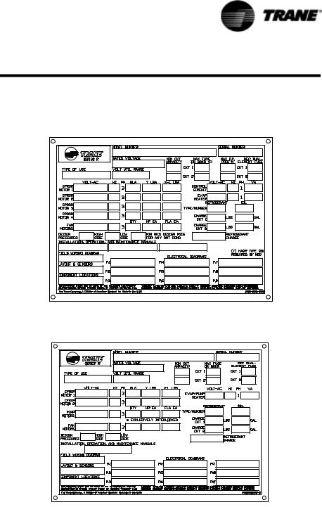
When the unit arrives, compare all nameplate data with ordering, submittal, and shipping information. A typical unit nameplate is shown in Figure 1.
Figure 1 Standatd Unit Nameplate
Figure 2 Pump Package Unit Nameplate
Nameplates
The RTAA outdoor unit nameplates are applied to the exterior of the Control
Panel. A compressor nameplate is located on each compressor.
Outdoor Unit Nameplate
The outdoor unit nameplate provides the following information:
Unit model and size description.
Unit serial number.
Identifies unit electrical requirements.
Lists correct operating charges of R-22 and oil.
RTAA-SVX01A-EN |
5 |

General Information
Lists unit test pressures.
Identifies installation, operation and maintenance and service data literature.
Lists drawing numbers for unit wiring diagrams. Pump Package Information - Optional
Compressor Nameplate
The compressor nameplate provides following information:
Compressor model number.
Compressor serial number.
Compressor electrical characteristics.
Utilization range.
Recommended refrigerant.
Unit Inspection
When the unit is delivered, verify that it is the correct unit and that it is properly equipped. Compare the information which appears on the unit nameplate with the ordering and submittal information.
Inspect all exterior components for visible damage. Report any apparent damage or material shortage to the carrier and make a “unit damage” notation on the carrier's delivery receipt. Specify the extent and type of damage found and notify the appropriate Trane Sales Office.
Do not proceed with installation of a damaged unit without sales office approval.
NOTE: If the Remote Evaporator Option is ordered, the remote evaporator will be shipped in a separate crate.
Inspection Checklist
To protect against loss due to damage incurred in transit, complete the following checklist upon receipt of the unit.
•Inspect the individual pieces of the shipment before accepting the unit. Check for obvious damage to the unit or packing material.
•Inspect the unit for concealed damage as soon as possible after delivery and before it is stored. Concealed damage must be reported within 15 days after receipt.
•If concealed damage is discovered, stop unpacking the shipment. Do not remove damaged material from the receiving location. Take photos of the damage. The owner must provide reasonable evidence that the damage did not occur after delivery.
•Notify the carrier’s terminal of the damage immediately, by phone and by mail. Request an immediate, joint inspection of the damage with the carrier and the consignee.
•Notify the Trane sales representative and arrange for repair. Do not repair the unit, however, until damage is inspected by the transportation representative.
Loose Parts Inventory
Check all the accessories and loose parts which are shipped with the unit against shipping list. Included in these items will be water vessel drain plugs, isolators, rigging and electrical diagrams, and service literature, which are placed inside the control panel and/or starter panel for shipment.
6 |
RTAA-SVX01A-EN |

General Information
Unit Description
The 70 through 125-ton Model RTAA units are helical-rotary type, air-cooled liquid chillers designed for installation outdoors. The unit has two compressors and the compressor circuits are completely assembled, hermetic packages. They are factory-piped, wired, leak-tested, de-hydrated, and tested for proper operation before shipment. The units are factory charged with refrigerant and oil.
The RTAA series features Trane's exclusive Adaptive Control™ logic with Clear Language Display. It monitors the control variables that govern the operation of the chiller unit. Adaptive Control logic can adjust these variables, when necessary, to optimize operational efficiencies, avoid chiller shutdown, and keep producing chilled water. An optional remote display is available to monitor unit operation from a remote location.
These dual-compressor units feature two independent circuits, one for each compressor. Compressor unloaders are solenoid actuated. Each refrigerant circuit is provided with filter drier, sight glass, electronic expansion valve, and charging valves.
The shell-and-tube type evaporator is manufactured in accordance with ASME standards. The evaporator is fully insulated and is equipped with water drain and vent connections. Packaged units have heat tape protection to
-20 F.
NOTE: Packaged units are factory charged with refrigerant and oil. Remote evaporator units are shipped with a holding charge of nitrogen and a partial charge of oil.
RTAA-SVX01A-EN |
7 |
General Information
Table 1 |
General RTAA Mechanical Specifications |
|
|
|
|
|||
|
|
|
|
|
|
|
|
|
|
|
|
|
|
Size |
|
|
|
|
|
|
70 |
80 |
90 |
100 |
110 |
125 |
Compressor |
|
|
|
|
|
|
|
|
|
|
|
|
|
|
|
|
|
|
Quantity |
|
2 |
2 |
2 |
2 |
2 |
2 |
|
|
|
|
|
|
|
|
|
|
Nominal Size (Tons)(1) |
35/35 |
40/40 |
50/40 |
50/50 |
60/50 |
60/60 |
|
Evaporator |
|
|
|
|
|
|
|
|
|
|
|
|
|
|
|
|
|
|
Water Storage |
(Gallons) |
39.8 |
37.8 |
34.4 |
32.1 |
53.4 |
45.8 |
|
|
|
|
|
|
|
|
|
|
|
(Liters) |
150.6 |
143.1 |
130.2 |
121.5 |
202.1 |
173.4 |
|
|
|
|
|
|
|
|
|
|
Min. Flow |
(GPM) |
84 |
96 |
108 |
120 |
132 |
150 |
|
|
|
|
|
|
|
|
|
|
|
(L/Sec) |
5.3 |
6.1 |
6.8 |
7.6 |
8.3 |
9.5 |
|
|
|
|
|
|
|
|
|
|
Max. Flow |
(GPM) |
252 |
288 |
324 |
360 |
396 |
450 |
|
|
|
|
|
|
|
|
|
|
|
(L/Sec) |
15.9 |
18.2 |
20.4 |
22.7 |
25.0 |
28.4 |
|
|
|
|
|||||
|
Refer to Pump Package Section for water storage of Pump and accocated piping. |
|
|
|||||
|
|
|
|
|
|
|
|
|
Condenser |
|
|
|
|
|
|
|
|
|
|
|
|
|
|
|
|
|
|
Qty of Coils |
|
4 |
4 |
4 |
4 |
4 |
4 |
|
|
|
|
|
|
|
|
|
|
Coil Length (Ft)(1) |
|
13/13 |
13/13 |
14/13 |
14/14 |
17/14 |
17/17 |
|
|
|
|
|
|
|
|
|
|
Coil Height (In) |
|
42 |
42 |
42 |
42 |
42 |
42 |
|
|
|
|
|
|
|
|
|
|
Number of Rows |
|
2 |
2 |
2 |
2 |
2 |
2 |
|
|
|
|
|
|
|
|
|
Condenser Fans |
|
|
|
|
|
|
|
|
|
|
|
|
|
|
|
|
|
|
Quantity (1) |
|
4/4 |
4/4 |
5/4 |
5/5 |
5/5 |
5/5 |
|
|
|
|
|
|
|
|
|
|
Diameter (In) |
|
30 |
30 |
30 |
30 |
30 |
30 |
|
|
|
|
|
|
|
|
|
|
Total Airflow (CFM) |
|
68,380 |
68,380 |
73,365 |
78,355 |
82,950 |
87,550 |
|
|
|
|
|
|
|
|
|
|
Nominal RPM |
|
855 |
855 |
855 |
855 |
855 |
855 |
|
|
|
|
|
|
|
|
|
|
Tip Speed (Ft./Min.) |
|
6715 |
6715 |
6715 |
6715 |
6715 |
6715 |
|
|
|
|
|
|
|
|
|
|
Motor HP (Ea.) |
|
1.1 |
1.1 |
1.1 |
1.1 |
1.1 |
1.1 |
|
|
|
|
|
|
|
||
Min. Starting/Oper. Ambient |
|
|
|
|
|
|
||
|
|
|
|
|
|
|
|
|
|
Std Unit (Deg. F) |
|
15 |
15 |
15 |
15 |
15 |
15 |
|
|
|
|
|
|
|
|
|
|
Low Amb. (Deg. F) |
|
-10 |
-10 |
-10 |
-10 |
-10 |
-10 |
General Unit |
|
|
|
|
|
|
|
|
|
|
|
|
|
|
|
|
|
|
Refrigerant |
|
HCFC-22 |
HCFC-22 |
HCFC-22 |
HCFC-22 |
HCFC-22 |
HCFC-22 |
|
|
|
|
|
|
|
|
|
|
No. of Independent |
|
|
|
|
|
|
|
|
Refrigerant Circuits |
|
2 |
2 |
2 |
2 |
2 |
2 |
|
|
|
|
|
|
|
|
|
|
% Min. Load (3) |
|
10 |
10 |
10 |
10 |
10 |
10 |
|
|
|
|
|
|
|
|
|
|
Refrig Charge |
(Lb) (1) |
58/58 |
61/61 |
73/61 |
73/73 |
98/73 |
98/98 |
|
|
|
|
|
|
|
|
|
|
|
(Kg) |
26/26 |
27/27 |
33/27 |
33/33 |
44/33 |
44/44 |
|
|
|
|
|
|
|
|
|
|
Oil Charge |
(Qts) (1.4) |
10/10 |
10/10 |
12/10 |
12/12 |
12/12 |
12/12 |
|
|
|
|
|
|
|
|
|
|
|
(L) |
10.6/10.6 |
10.6/10.6 |
12.7/10.6 |
12.7/12.7 |
12.7/12.7 |
12.7/12.7 |
Notes:
1.Data containing information on two circuits shown as follows: ckt1/ckt2
2.Minimum start-up/operating ambient based on a 5 mph wind across the condenser.
3.Percent minimum load is for total machine, not each individual circuit.
4.Trane Part Change # Oil-31 (see service bulletin SCOM-SB-1)
8 |
RTAA-SVX01A-EN |
General Information
Model Number Coding System
The model number for the unit is comprised of numbers and letters which represent features of the equipment. Shown on the chart in Figure 3 are samples of typical unit model numbers, followed by the coding system.
Each position, or group of positions, in the number is used to represent a feature. For example, in Figure 3, position 8 of the unit model number, Unit Voltage, contains the number “4”. From the chart, it can be seen that a “4” in this position means that the unit voltage is 460/60/3.
.
Figure 3 Model Number Coding System:
Model Number |
RTA |
A |
070 |
4 |
Y |
A0 |
1 |
B |
1 |
D |
A |
0 |
Digit Number |
0 |
|
|
|
|
1 |
|
|
|
|
|
2 |
|
|
|
|
|
|
|
|
|
|
|
|
|
Digit Position |
1 2 3 |
4 |
5 6 7 |
8 |
9 |
0 1 |
2 |
3 |
4 |
5 |
6 |
0 |
|
|
|
|
|
|
|
|
|
|
|
|
|
Digit 1-2
Unit Model
RT |
Rotary Chiller |
Digit 3
Unit Type
A Air Cooled
Digit 4
Development Sequence
A First Sequence
Digit 5,6,7
Nominal Capacity
070 70 Nominal Tons
080 80 Nominal Tons
090 90 Nominal Tons
100 100 Nominal Tons
110 110 Nominal Tons
125 125 Nominal Tons
Digit 8
Unit Voltage
D 380/60/3
A 200/60/3
C 230/60/3
K 400/50/3
4460/60/3
5575/60/3
Digit 9
Compressor Starter Type
Y Y -Delta Closed Transition
X X-Line (Across the Line)
Digit 10, 11
Design Sequence
AO |
First Sequence (Factory Input) |
Digit12
Evaporator Leaving Temperature
1Standard 40 to 65 F
2Low 0 to 39 F
3Ice-Making 20 to 65 F
Digit 13
Condenser Coil Fin Material
A Aluminum
2 CompleteCoat dipped coils
4 copper fins
Digit 14
Agency Listing
0 No Agency Listing
3 C-UL Listed
Digit 15
Control Interface
CDeluxe without Communication
DDeluxe with Communication
L LCI-C (LonTalk)
Digit 16
Chilled Water Reset
0No Chilled Water Reset
1Based on Return Water Temp
2Based on Outside Air Temp
Digit 17
Miscellaneous Factory Installed
Options
AArchitectural Louvered Panels
BControl Power Transformer
CConvenience Outlet
DLow Ambient Lockout Sensor
FPower Disconnect
GLow Ambient Operation
HSound Attenuator
JRemote Evaporator
KCoil Protection
MAccess Guard
NNeoprene Isolators
PCircuit Breaker
RRemote Display Panel
0 Size C 2 HP Pump Package
1 Size D 3 HP Pump Package
2 Size D 5 HP Pump Package
3 Size E 2 HP Pump Package
4 Size E 3 HP Pump Package
5 Size F 5 HP Pump Package
6 Size F 7 HP Pump Package
7 Size G 3 HP Pump Package
8 Size G 5 HP Pump Package
RTAA-SVX01A-EN |
9 |

Installation — Mechanical
Installation Responsibilities
Generally, the contractor must do the following when installing an RTAA unit:
•Install unit on a flat foundation, level (within 1/4” [6 mm] across the length and width of the unit), and strong enough to support unit loading.
•Install unit per the instructions contained in the Installation-Mechanical and Installation-Electrical sections of this manual.
•Where specified, provide and install valves in water piping upstream and downstream of evaporator water connections to isolate the evaporator for maintenance, and to balance/trim system.
•Furnish and install flow switch to prove chilled water flow.
•Furnish and install pressure gauges in inlet and outlet piping of the evaporator.
•Furnish and install a drain valve to the bottom of the evaporator.
•Supply and install a vent cock to the top of the evaporator.
•Furnish and install strainers ahead of all pumps and automatic modulating valves.
•Provide and install field wiring.
•Install heat tape and insulate the chilled water lines and any other portions of the system, as required, to prevent sweating under normal operating conditions or freezing during low ambient temperature conditions.
•Start unit under supervision of a qualified service technician.
For remote evaporator units only
Furnish and install refrigerant piping, liquid line isolation valves, refrigerant, and oil, per instructions outlined in this manual.
Storage
Extended storage of the outdoor unit prior to installation requires the following precautionary measures:
Store the outdoor unit in a secure area.
At least every three months (quarterly), check the pressure in the refrigerant circuits to verify that the refrigerant charge is intact. If it is not, contact a qualified service organization and the appropriate Trane sales office.
Close the discharge and liquid line isolation valves.
Location Requirements
Noise Considerations
•Refer to Trane Engineering Bulletins for application information on RTAA chillers.
•Locate the outdoor unit away from sound-sensitive areas.
•If required, install rubber vibration isolators in all water piping and use flexible electrical conduit.
•Refer to “Unit Isolation”.
•Consult an acoustical engineer for critical applications.
10 |
RTAA-SVX01A-EN |
Installation — Mechanical
Foundation
Provide rigid, non-warping mounting pads or a concrete foundation of sufficient strength and mass to support the outdoor unit operating weight (i.e., including completed piping, and full operating charges of refrigerant, oil and water). Refer to Figure 13 for unit operating weights. Once in place, the outdoor unit must be level within 1/4” (6.4 mm) over its length and width. The Trane Company is not responsible for equipment problems resulting from an improperly designed or constructed foundation.
RTAA-SVX01A-EN |
11 |
Installation — Mechanical
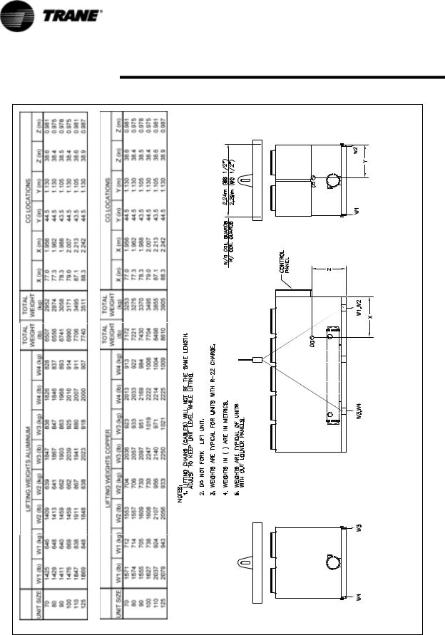
Figure 4 RTAA Rigging and Lifting Weights – Packaged Unit
12 |
RTAA-SVX01A-EN |
Installation — Mechanical
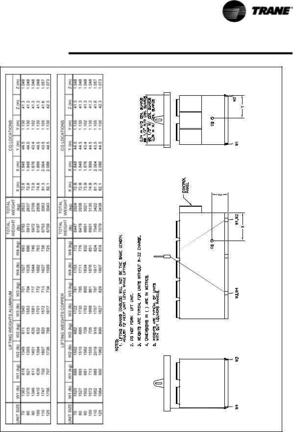
Figure 5 RTAA Rigging and Lifting Weights – Remote Evaporator
RTAA-SVX01A-EN |
13 |
Installation — Mechanical
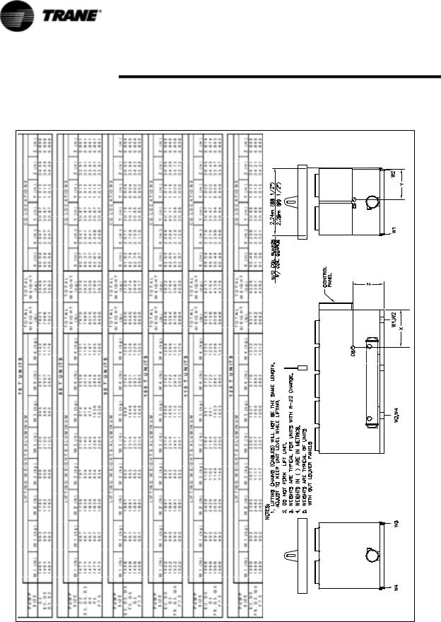
Figure 6 RTAA Rigging and Lifting Weights –Pump Package Aluminum Fins
14 |
RTAA-SVX01A-EN |
Installation — Mechanical
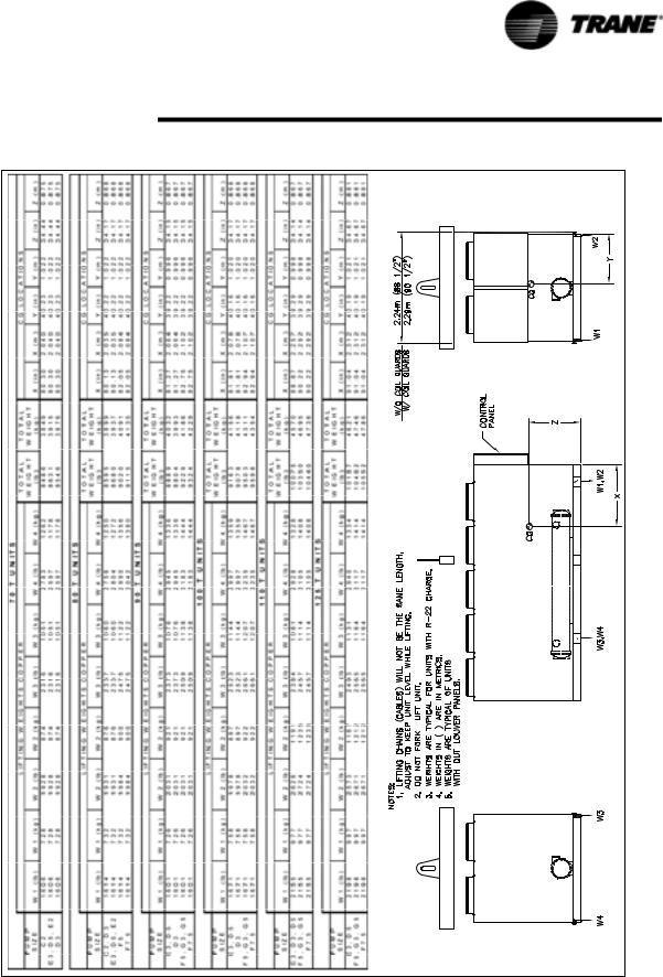
Figure 7 RTAA Rigging and Lifting Weights –Pump Package Copper Fins
RTAA-SVX01A-EN |
15 |

Installation — Mechanical
Clearances
Provide enough space around the outdoor unit to allow the installation and maintenance personnel unrestricted access to all service points. Refer to submittal drawings for the unit dimensions, to provide sufficient clearance for the opening of control panel doors and unit service. Refer to Figure 8, Figure 9 and Figure 12 for minimum clearances. In all cases, local codes which require additional clearances will take precedence over these recommendations.
NOTE: If the outdoor unit configuration requires a variance to the clearance dimensions, contact your Trane Sales Office Representative. Also refer to Trane Engineering Bulletins for application information on RTAA chillers.
Additional Location Requirements for Remote Evaporator Only
The Remote evaporator must be installed in a conditioned space, unless:
•The ambient temperature is always greater than 32 F.
•The system circulating liquid is a non-freezing glycol-type solution, selected for the prevailing ambient temperature. The evaporator is protected from freezing by properly installed and applied insulation and heat tape.
CAUTION
Freezing Equipment Damage!
To prevent damage due to freezing, do not install the unit outside without adequate freeze protection.
The remote evaporator should be mounted on a base of suitable strength to support the operating weight. Remote evaporator weights and mounting locations are shown in Figure 10 and Figure 11.
The remote evaporator must be level when installed. Be sure to allow adequate clearance for water and refrigerant piping connection, performance of service procedures, reading of gauges and thermometers, and operation of valves. Space must be allowed at one end of the evaporator to pull tubes, if required.
Rigging
The Model RTAA chiller should be moved by lifting. Refer to Figure 4 for typical unit lifting and weights. Refer to the rigging diagram that ships with each unit for specific “per unit” weight data.
WARNING
Heavy Objects!
Do not use cables (chains or slings) except as shown. Each of the cables (chains or slings) used to lift the unit must be capable of supporting the entire weight of the unit. Lifting cables (chains or slings) may not be of the same length. Adjust as necessary for even unit lift. Other lifting arrangements may cause equipment or property-only damage. Failure to properly lift unit may result in death or serious injury. See details below.
16 |
RTAA-SVX01A-EN |

Installation — Mechanical
Lifting Procedure
CAUTION
Equipment Damage!
To prevent damage do not use a forklift to lift or push the unit.
Position lifting beam so that cables do not contact the unit.
•Install chains and safety chains through the six lifting plates provided on the unit.
•Attach lifting chains or cables to the chains installed above. Each cable alone must be strong enough to lift the chiller.
•Attach cables to lifting beam. Total lifting weight, lifting weight distribution and required lifting beam dimensions are shown in Figure 4 and Figure 5 and on the rigging diagram shipped with each unit. Lifting beam crossbars must be positioned so lifting cables do not contact the sides of the unit.
RTAA-SVX01A-EN |
17 |
Installation — Mechanical
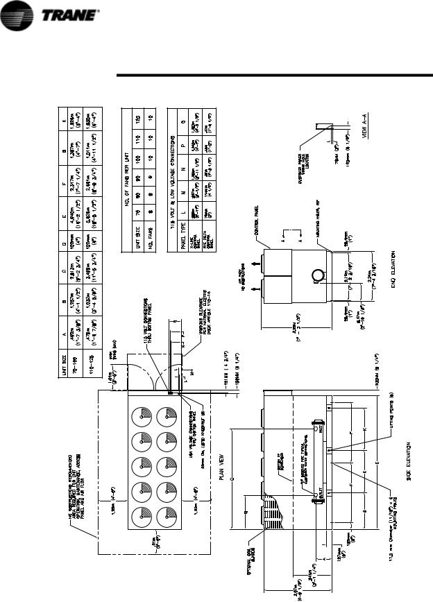
Figure 8 Dimensions and Clearances for RTAA Packaged Unit 70 – 125 Tons
18 |
RTAA-SVX01A-EN |
Installation — Mechanical
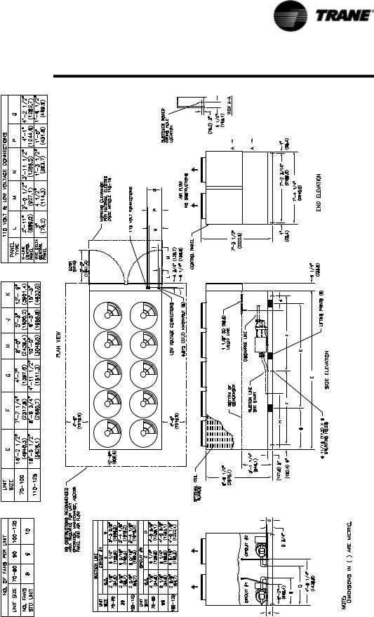
Figure 9 Dimensions and Clearances for RTAA with Remote Evaporator 70 – 125 Tons
RTAA-SVX01A-EN |
19 |
Installation — Mechanical
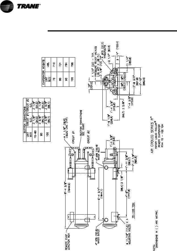
Figure 10 Remote Evaporator Dimensions, RTAA 70 – 125 Tons
20 |
RTAA-SVX01A-EN |
Installation — Mechanical
Figure 11 Remote Evaporator Dimensions, RTAA 110 – 125 Tons
RTAA-SVX01A-EN |
21 |

Installation — Mechanical
Figure 12 Dimensions and Clearances for RTAA with Pump Package 70 – 125 Tons
22 |
RTAA-SVX01A-EN |

Installation — Mechanical
Unit Isolation
There are two mounting methods that will minimize sound and vibration problems. They are the direct-mount method and the isolator-mount method.
Direct Mounting
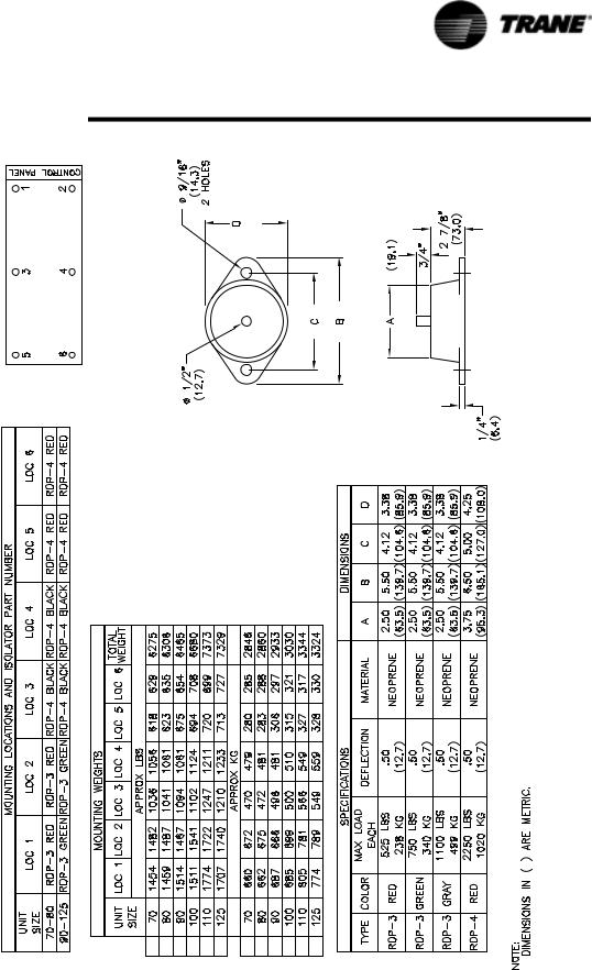
The unit can be direct-mounted on an isolated concrete pad or on isolated concrete footings at each mounting location. Refer to Figure 13 for unit operating weights. A mounting hole is provided in the base of the unit frame at each mounting location. Provide a means of securely anchoring the unit to the mounting surface. Level the unit carefully. Refer to “Unit Leveling”.
Neoprene Isolators
Install the optional neoprene mounting isolators at each mounting location. Refer to Figure 13 for isolator selection, placement and loading information. Isolators are identified by color and by the isolator part number.
Bolt the isolators to the mounting surface. Do not fully tighten the mounting bolts. Mount the unit on the isolators and install a 1/2”nut on each isolator positioning pin. Maximum isolator deflection should be approximately 1/4- inch. Level the unit carefully. Refer to “Unit Leveling”. Now fully tighten isolator mounting bolts.
Unit Leveling
Before snugging down the mounting bolts, level the unit carefully. Check unit level end-to-end by placing a level on the top surface of the unit frame. Unit should be level to within 1/4-inch (6.35 mm) over its length. Place the level on the unit frame to check front-to-back level. Adjust to within 1/4” (35 mm) of level front-to-back. Use the adjustable spring isolators or shims to level
the unit.
Water Piping
Thoroughly flush all water piping to the unit before making the final piping connections to the unit.
CAUTION
Use Piping Strainers!
To prevent evaporator damage, pipe strainers must be installed in the water supplies to protect components from water born debris. Trane is not responsible for equipment-only-damage caused by water born debris.
CAUTION
Proper Water Treatment!
The use of untreated or improperly treated water in a RTAA may result in scaling, erosion, corrosion, algae or slime. It is recommended that the services of a qualified water treatment specialist be engaged to determine what water treatment, if any, is required. Trane assumes no responsibility for equipment failures which result from untreated or improperly treated water, or saline or brackish water.
RTAA-SVX01A-EN |
23 |
Installation — Mechanical
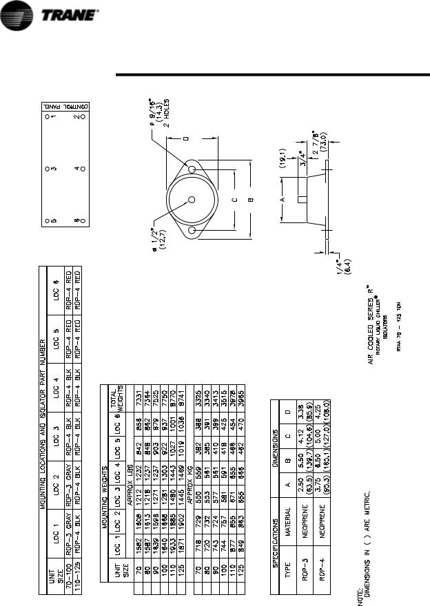
Figure 13 Isolator Placement for Typical RTAA Packaged Unit 70 – 125 Tons
24 |
RTAA-SVX01A-EN |
Installation — Mechanical
Figure 14 Isolator Placement for RTAA with Remote Evaporator
RTAA-SVX01A-EN |
25 |

Installation — Mechanical
Evaporator Water Piping
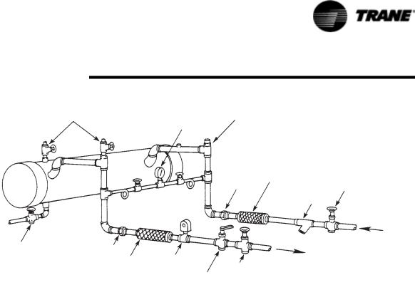
Figure 15 illustrates typical evaporator piping components. Components and layout will vary slightly, depending on the location of connections and the water source.
CAUTION
Evaporator Damage!
The chilled water connections to the evaporator are to be “victualic” type connections. Do not attempt to weld these connections, as the heat generated from welding can cause internal damage to the evaporator.
The chilled water connections are on the left side of the unit (when facing the control panel). If it is necessary for the chilled water piping to enter the unit from the right side, elbows can be used to route the piping 180° over the top of the evaporator.
A vent is provided on the top of the evaporator at the leaving water end. Be sure to provide additional vents at high points in the piping to bleed air from the chilled water system. Install necessary pressure gauges to monitor the entering and leaving chilled water pressures.
CAUTION
Chilled Water Components Damage!
To prevent damage to chilled water components, do not allow evaporator pressure (maximum working pressure) to exceed 215 psig.
Provide shutoff valves in lines to the gauges to isolate them from the system when they are not in use. Use rubber vibration eliminators to prevent vibration transmission through the water lines.
If desired, install thermometers in the lines to monitor entering and leaving water temperatures. Install a balancing valve in the leaving water line to control water flow balance. Install shutoff valves on both the entering and leaving water lines so that the evaporator can be isolated for service.
A pipe strainer must be installed in the entering water line to prevent waterborne debris from entering the evaporator.
26 |
RTAA-SVX01A-EN |
Installation — Mechanical
6ENTS |
6ALVED |
2ELIEF |
|
0RESSURE |
|
||
|
'AUGE |
6ALVE |
|
|
|
|
|
|
|
|
6IBRATION |
|
|
5NION |
%LIMINATOR |
|
|
'ATE 6ALVE |
|
|
|
|
ATER |
|
|
|
3TRAINER |
$RAIN |
5NION |
|
|
|
&LOW |
|
|
|
6IBRATION |
|
|
|
3WITCH |
'ATE 6ALVE |
|
|
%LIMINATOR |
||
|
/PTIONAL |
|
|
|
|
"ALANCINGN6ALVE |
Figure 15 Suggested Piping for Typical RTAA Evaporator
Evaporator Piping Components
“Piping components” include all devices and controls used to provide proper water system operation and unit safety. These components and their general locations are given below.
Entering Chilled Water Piping
•Air vents (to bleed air from system).
•Water pressure gauges with shutoff valves.
•Vibration eliminators.
•Shutoff (isolation) valves.
•Thermometers (if desired).
•Cleanout tees.
•Relief valve.
•Pipe strainer.
Leaving Chilled Water Piping Air vents (to bleed air from system).
•Air vents (to bleed air from system).
•Water pressure gauges with shutoff valves.
•Vibration eliminators. Shutoff (isolation) valves.
•Thermometers.
•Cleanout tees.
•Balancing valve.
•Flow Switch (If desired).
RTAA-SVX01A-EN |
27 |

Installation — Mechanical
CAUTION
Evaporator Damage!
To prevent evaporator damage, do not exceed 215 psig (14.6 bar) evaporator water pressure.
Evaporator Drain
A 3/4” drain connection is located under the outlet end of the evaporator. This may be connected to a suitable drain to permit evaporator drainage during unit servicing. A shutoff valve must be installed on the drain line.
Chilled Water Flow Switch
Chilled water flow protection is provided by the UCM without the need for a chilled water flow switch. A flow switch for chilled water is strictly discretionary but if not installed, a signal must be sent to the chiller to indicate that water flow has been established, eg. chilled water pump motor starter auxiliary contacts, building automation system, etc.
If additional chilled water flow protection is desired, use a field-installed flow switch or differential pressure switch with the pump motor starter auxiliary contacts to sense system water flow. Install and wire the flow switch in series with the chilled water pump motor starter auxiliaries (refer to “Interlock Wiring”).
Specific connection and schematic wiring diagrams are shipped with the unit. Some piping and control schemes, particularly those using a single water pump for both chilled and hot water, must be analyzed to determine how and or if a flow sensing device will provide desired operation.
Follow the manufacturer's recommendations for selection and installation procedures. General guidelines for flow switch installation are outlined below:
1.Mount the switch upright, with a minimum of 5 pipe diameters of straight horizontal run on each side. Do not install close to elbows, orifices or valves.
NOTE: The arrow on the switch must point in the direction of flow.
2. To prevent switch fluttering, remove all air from the water system.
NOTE: The UCM provides a 6-second time delay after a “loss-of flow” diagnostic before shutting the unit down. Contact a qualified service representative if nuisance machine shutdowns persist.
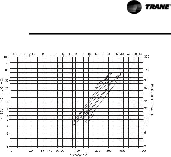
3.Adjust the switch to open when water flow falls below nominal. Evaporator data is shown in Figure 16 Refer to Table 1 for minimum flow recommendations. Flow switch contacts are closed on proof of water flow.
4.Install a pipe strainer in the entering evaporator water line to protect components from water-borne debr‘is.
28 |
RTAA-SVX01A-EN |
Installation — Mechanical
Figure 16 RTAA Evaporator Water Pressure Drop
Water Treatment
Using untreated or improperly treated water in these units may result in inefficient operation and possible tube damage. Consult a qualified water treatment specialist to determine whether treatment is needed.
Customer Note
The use of improperly treated or untreated water in this equipment may result in scaling, erosion, corrosion, algae or slime. The services of a qualified water treatment specialist should be engaged to determine what treatment, if any, is advisable. The Trane Company warranty specifically excludes liability for corrosion, erosion or deterioration of Trane equipment. Trane assumes no responsibilities for the results of the use of untreated or improperly treated water, or saline or brackish water.
Water Pressure Gauges
Install field-supplied pressure gauges (with manifolds, whenever practical) as shown in Figure 15. Locate pressure gauges or taps in a straight run of pipe; avoid placement near elbows, etc. Be sure to install the gauges at the same elevation.
To read manifolded pressure gauges, open one valve and close the other (depending upon the reading desired). This eliminates errors resulting from differently calibrated gauges installed at unmatched elevations.
RTAA-SVX01A-EN |
29 |

Installation — Mechanical
Water Pressure Relief Valves
Install a water pressure relief valve in the evaporator inlet piping between the evaporator and the inlet shutoff valve, as shown in Figure 15. Water vessels with close-coupled shutoff valves have a high potential for hydrostatic pressure buildup on a water temperature increase. Refer to applicable codes for relief valve installation guidelines.
Freeze Protection
If the unit will remain operational at subfreezing ambient temperatures, the chilled water system must be protected from freezing, following the steps listed below:
1.Heat tape is factory-installed on the packaged unit evaporator and will protect it from freezing in ambient temperatures down to -20 F.
2.Install heat tape on all water piping, pumps, and other components that may be damaged if exposed to freezing temperatures. Heat tape must be designed for low ambient temperature applications. Heat tape selection should be based on the lowest expected ambient temperature.
3.Add a non-freezing, low temperature, corrosion inhibiting, heat transfer fluid to the chilled water system. The solution must be strong enough to provide protection against ice formation at the lowest anticipated ambient temperature. Refer to Table 1 for evaporator water storage
capacities.
NOTE: Use of glycol type antifreeze reduces the cooling capacity of the unit and must be considered in the design of the system specifications.
30 |
RTAA-SVX01A-EN |
 Loading...