


HUV
Table of contents
 Loading...
SAFETY WARNING
Only qualified personnel should install and service the equipment. The installation, starting up, and
servicing of heating, ventilating, and air-conditioning equipment can be hazardous and requires specific
knowledge and training. Improperly installed, adjusted or altered equipment by an unqualified person could
result in death or serious injury. When working on the equipment, observe all precautions in the literature
and on the tags, stickers, and labels that are attached to the equipment.
Horizontal Unit Ventilator
Classroom Unit Ventilator—Model HUV
January 2013 UV-SVN02C-EN
Installation, Operation,
and Maintenance
Models
“C” and later Design Sequence
HUVC
750 cfm—2000 cfm
© 2013 Trane All rights reserved UV-SVN02C-EN
Warnings, Cautions, and Notices
Warnings, Cautions, and Notices. Note that
warnings, cautions, and notices appear at appropriate
intervals throughout this manual. Warnings are provide to
alert installing contractors to potential hazards that could
result in personal injury or death. Cautions are designed to
alert personnel to hazardous situations that could result in
personal injury, while notices indicate a situation that
could result in equipment or property-damage-only
accidents.
Your personal safety and the proper operation of this
machine depend upon the strict observance of these
precautions.
Important
Environmental Concerns!
Scientific research has shown that certain man-made
chemicals can affect the earth’s naturally occurring
stratospheric ozone layer when released to the
atmosphere. In particular, several of the identified
chemicals that may affect the ozone layer are refrigerants
that contain Chlorine, Fluorine and Carbon (CFCs) and
those containing Hydrogen, Chlorine, Fluorine and
Carbon (HCFCs). Not all refrigerants containing these
compounds have the same potential impact to the
environment. Trane advocates the responsible handling of
all refrigerants-including industry replacements for CFCs
such as HCFCs and HFCs.
Responsible Refrigerant Practices!
Trane believes that responsible refrigerant practices are
important to the environment, our customers, and the air
conditioning industry. All technicians who handle
refrigerants must be certified. The Federal Clean Air Act
(Section 608) sets forth the requirements for handling,
reclaiming, recovering and recycling of certain
refrigerants and the equipment that is used in these
service procedures. In addition, some states or
municipalities may have additional requirements that
must also be adhered to for responsible management of
refrigerants. Know the applicable laws and follow them.
ATT EN TI ON : Warnings, Cautions, and Notices appear at
appropriate sections throughout this literature. Read
these carefully:
WARNING
Indicates a potentially hazardous
situation which, if not avoided, could
result in death or serious injury.
CAUTIONs
Indicates a potentially hazardous
situation which, if not avoided, could
result in minor or moderate injury. It
could also be used to alert against
unsafe practices.
NOTICE:
Indicates a situation that could result in
equipment or property-damage only
WARNI NG
Proper Field Wiring and Grounding
Required!
All field wiring MUST be performed by qualified
personnel. Improperly installed and grounded field
wiring poses FIRE and ELECTROCUTION hazards. To
avoid these hazards, you MUST follow requirements for
field wiring installation and grounding as described in
NEC and your local/state electrical codes. Failure to
follow code could result in death or serious injury.
WARNING
Personal Protective Equipment (PPE)
Required!
Installing/servicing this unit could result in exposure to
electrical, mechanical and chemical hazards.
• Before installing/servicing this unit, technicians
MUST put on all PPE required for the work being
undertaken. ALWAYS refer to appropriate MSDS
sheets and OSHA guidelines for proper PPE.
• When working with or around hazardous chemicals,
ALWAYS refer to the appropriate MSDS sheets and
OSHA guidelines for information on allowable
personal exposure levels, proper respiratory
protection and handling instructions.
• If there is a risk of arc or flash, technicians MUST put
on all PPE in accordance with NFPA 70E or other
country-specific requirements for arc flash
protection, PRIOR to servicing the unit.
Failure to follow instructions could result in death or
serious injury.
WARNI NG
Contains Refrigerant!
System contains oil and refrigerant under high
pressure. Recover refrigerant to relieve pressure before
opening the system. See unit nameplate for refrigerant
type. Do not use non-approved refrigerants, refrigerant
substitutes, or refrigerant additives.
Failure to follow proper procedures or the use of non-
approved refrigerants, refrigerant substitutes, or
refrigerant additives could result in death or serious
injury or equipment damage.
Warnings, Cautions, and Notices
UV-SVN02C-EN 3
Trademarks
ComfortLink, Rover, Tracer, Tracer Summit, Trane, and the
Trane logo are trademarks or registered trademarks of
Trane in the United States and other countries. All
trademarks referenced in this document are the
trademarks of their respective owners.
BACnet is a registered trademark of American Society of
Heating, Refrigerating and Air-Conditioning Engineers
(ASHRAE); Echelon, LonTalk, and L
ONWORKS are registered
trademarks of Echelon Corporation; Energizer is a
registered trademark of Eveready Battery Company, Inc.;
National Electrical Code, National Fire Protection
Association, and NEC are registered trademarks of the
National Fire Protection Association.
WARNING
R-410A Refrigerant under Higher Pressure
than R-22!
Some of the units described in this manual uses R-410A
refrigerant which operates at higher pressures than
R-22 refrigerant. Use ONLY R-410A rated service
equipment or components with this unit. For specific
handling concerns with R-410A, please contact your
local Trane representative.
Failure to use R-410A rated service equipment or
components could result in equipment or components
exploding under R-410A high pressures which could
result in death, serious injury, or equipment damage.
WARNING
Hazard of Explosion!
Use only dry nitrogen with a pressure regulator for
pressurizing unit. Do not use acetylene, oxygen or
compressed air or mixtures containing them for
pressure testing. Do not use mixtures of a hydrogen
containing refrigerant and air above atmospheric
pressure for pressure testing as they may become
flammable and could result in an explosion. Refrigerant,
when used as a trace gas should only be mixed with
dry nitrogen for pressurizing units. Failure to follow
these recommendations could result in death or serious
injury or equipment or property-only damage.

4 UV-SVN02C-EN
Table of Contents
Model Number Descriptions . . . . . . . . . . . . . . 6
General Information . . . . . . . . . . . . . . . . . . . . . 8
Unit Description . . . . . . . . . . . . . . . . . . . . . 8
Options . . . . . . . . . . . . . . . . . . . . . . . . . . . . 8
Unit Ventilator Controls . . . . . . . . . . . . . . 10
ECM Application Notes . . . . . . . . . . . . . . . . . . 12
Dimensions and Weights . . . . . . . . . . . . . . . . 13
Unit Location and Clearances . . . . . . . . . 13
Receiving and Handling . . . . . . . . . . . . . . . . . 19
Pre-Installation . . . . . . . . . . . . . . . . . . . . . . . . . 20
Jobsite Inspection . . . . . . . . . . . . . . . . . . 20
Jobsite Storage . . . . . . . . . . . . . . . . . . . . 20
Installation—Mechanical . . . . . . . . . . . . . . . . 21
Location Considerations . . . . . . . . . . . . . . . 21
Unit Mounting . . . . . . . . . . . . . . . . . . . . . . . 21
Horizontal Recessed Mounting . . . . . . . . 21
Installation—Piping . . . . . . . . . . . . . . . . . . . . . 23
Trane Piping Packages (Option) . . . . . . . 23
Split System Units . . . . . . . . . . . . . . . . . . 23
Refrigerant Piping . . . . . . . . . . . . . . . . . . 23
Steam Piping . . . . . . . . . . . . . . . . . . . . . . 24
Modulating Water Valves (Option) . . . . . 24
Plumbing . . . . . . . . . . . . . . . . . . . . . . . . . . 25
Manual Opener . . . . . . . . . . . . . . . . . . . . . 26
Isolation Valves . . . . . . . . . . . . . . . . . . . . . . 26
Installation . . . . . . . . . . . . . . . . . . . . . . . . 26
Servicing/Removal of Valves . . . . . . . . . . 26
Heating Coils with Direct Expansion Cooling
. . . . . . . . . . . . . . . . . . . . . . . . . . . . . . . . . . . . . 27
Installation—Sensors . . . . . . . . . . . . . . . . . . . 28
Control Options . . . . . . . . . . . . . . . . . . . . . . 28
Installing Wall-Mounted Wired Sensors . 29
Location Considerations . . . . . . . . . . . . . 30
Location Considerations for Wireless Zone
Sensors . . . . . . . . . . . . . . . . . . . . . . . . . . . 30
Fan Mode Switch Installation . . . . . . . . . 30
Zone Sensor Installation . . . . . . . . . . . . . 30
Wireless Sensors . . . . . . . . . . . . . . . . . . . . . 31
Address Setting . . . . . . . . . . . . . . . . . . . . 31
Observing the Receiver for Readiness to As-
sociate . . . . . . . . . . . . . . . . . . . . . . . . . . . . .32
Associating the Sensor to the Receiver . .32
Testing Signal Strength and Battery Status
. . . . . . . . . . . . . . . . . . . . . . . . . . . . . . . . . . .33
Configuring the Wireless Display Sensor
(Model WDS only) . . . . . . . . . . . . . . . . . . .34
Sensor Operations . . . . . . . . . . . . . . . . . . .36
Wireless Sensor Specifications . . . . . . . . . 39
Installation—Electrical . . . . . . . . . . . . . . . . . . .41
Wiring . . . . . . . . . . . . . . . . . . . . . . . . . . . . .41
Electrical Wiring . . . . . . . . . . . . . . . . . . . . .41
Electric Heat Units . . . . . . . . . . . . . . . . . . . 41
Heating Coils with Direct Expansion Cooling
. . . . . . . . . . . . . . . . . . . . . . . . . . . . . . . . . . .42
ECM Overview and Setup . . . . . . . . . . . . . . . . 43
Overview . . . . . . . . . . . . . . . . . . . . . . . . . . . . .43
General Information . . . . . . . . . . . . . . . . . . .43
Trane BLDC Motor . . . . . . . . . . . . . . . . . . .43
ECM Engine Controller . . . . . . . . . . . . . . .43
Standard Adapter Board . . . . . . . . . . . . . .44
CSTI Adapter Board . . . . . . . . . . . . . . . . . .44
Installation and Initial Setup . . . . . . . . . . . .45
Installation and Initial Setup . . . . . . . . . . .45
Adjustment and Configuration of the Engine
Board . . . . . . . . . . . . . . . . . . . . . . . . . . . . . .47
Status Display . . . . . . . . . . . . . . . . . . . . . . .48
Initial Setup and Configuration . . . . . . . . .53
Configuration . . . . . . . . . . . . . . . . . . . . . . . . .53
Configuring the ECM Engine Controller . .53
Configuring the ECM Engine Board . . . . .58
Time Clock . . . . . . . . . . . . . . . . . . . . . . . . . . . . . .63
Setting the Time Clock . . . . . . . . . . . . . . . .63
Wired Controllers—Communication Wiring 65
Wiring Installation (Tracer ZN520) . . . . . . .65
Device Addressing . . . . . . . . . . . . . . . . . . .65
Recommended Communication Wiring Prac-
tices . . . . . . . . . . . . . . . . . . . . . . . . . . . . . . .65
Wiring Installation (Tracer UC400) . . . . . . .65
Wiring Overview Outline . . . . . . . . . . . . . .66

UV-SVN02C-EN 5
General Instructions . . . . . . . . . . . . . . . . . 66
BACnet MS/TP Link . . . . . . . . . . . . . . . . . 66
Power Supply . . . . . . . . . . . . . . . . . . . . . . 67
Pre-Start . . . . . . . . . . . . . . . . . . . . . . . . . . . . . . . 69
Pre-Start-up Checklist . . . . . . . . . . . . . . . 69
Startup . . . . . . . . . . . . . . . . . . . . . . . . . . . . . . . . 70
Tracer ZN520 Unit Startup . . . . . . . . . . . . 70
Tracer UC400 Unit Startup . . . . . . . . . . . 70
General Information . . . . . . . . . . . . . . . . . 70
Fan Mode Switch Operation . . . . . . . . . . 70
Tracer ZN520 Operation . . . . . . . . . . . . . 70
UC400 Controller Operation . . . . . . . . . . 71
Tracer ZN520 Sequence of Operation . . . 71
Cooling Operation (Tracer ZN520) . . . . . 72
Fan Mode Operation (Tracer ZN520) . . . 73
UC400 Sequence of Operation . . . . . . . . . 78
Power-up Sequence (UC400) . . . . . . . . . 78
Random Start (UC400) . . . . . . . . . . . . . . . 78
Occupancy Modes (UC400) . . . . . . . . . . . 78
Timed Override Control (UC400) . . . . . . 79
Zone Temperature Control (UC400) . . . . 79
Discharge Air Tempering (UC400) . . . . . 80
Heating or Cooling Mode (UC400) . . . . . 80
Entering Water Temperature Sampling Func-
tion (UC400) . . . . . . . . . . . . . . . . . . . . . . . 80
Fan Operation (UC400) . . . . . . . . . . . . . . 80
Exhaust Control (UC400) . . . . . . . . . . . . . 81
Valve Operation (UC400) . . . . . . . . . . . . . 81
Modulating Outdoor/Return Air Damper
(UC400) . . . . . . . . . . . . . . . . . . . . . . . . . . . 82
Two-position Control Of A Modulating Out-
door Air Damper (UC400) . . . . . . . . . . . . 83
Electric Heat Operation (UC400) . . . . . . . 83
Dehumidification Operation (UC400) . . . 83
Peer-to-peer Communication (UC400) . . 83
Unit Protection Strategies (UC400) . . . . . 83
Maintenance . . . . . . . . . . . . . . . . . . . . . . . . . . . 85
Service Access . . . . . . . . . . . . . . . . . . . . . 85
Periodic Maintenance . . . . . . . . . . . . . . . 85
Filters . . . . . . . . . . . . . . . . . . . . . . . . . . . . . 85
Removal of the Drain Pan . . . . . . . . . . . . .85
Removal of the Fanboard and Coil Cleaning
. . . . . . . . . . . . . . . . . . . . . . . . . . . . . . . . . . .86
Lubrication: Fan Shaft . . . . . . . . . . . . . . . .86
Motor . . . . . . . . . . . . . . . . . . . . . . . . . . . . . .87
Modulating Valves (3-Wire Floating) . . . .87
Preventive Maintenance . . . . . . . . . . . . . . . .87
Diagnostics . . . . . . . . . . . . . . . . . . . . . . . . . . . . .88
Troubleshooting Checklist . . . . . . . . . . . . .88
Output Testing and Diagnostics (Tracer
ZN520)
. . . . . . . . . . . . . . . . . . . . . . . . . . . . . . .89
Output Testing and Diagnostics (UC400) . .93
Output Testing (UC400) . . . . . . . . . . . . . . .93
Diagnostics (UC400) . . . . . . . . . . . . . . . . . 93
Troubleshooting (Wireless Controls) . . . . .94
Troubleshooting (Tracer ZN520) . . . . . . .100
Troubleshooting (UC400) . . . . . . . . . . . .101
Troubleshooting (ECM) . . . . . . . . . . . . . .103
General Information (ECM) . . . . . . . . . . .104
Troubleshooting Information (ECM) . . .104
Replacing ECM Components . . . . . . . . . . . .106
Circuit Modules Replacement Notes/Work In-
structions . . . . . . . . . . . . . . . . . . . . . . . . .107
Softsetting the IMC Address of an ECM En-
gine Module . . . . . . . . . . . . . . . . . . . . . . . 107
Accessories . . . . . . . . . . . . . . . . . . . . . . . . . . . .109
Wallboxes . . . . . . . . . . . . . . . . . . . . . . . . . . . 109
General Instructions . . . . . . . . . . . . . . . . .109
Installation in Masonry Walls . . . . . . . . .111
Installation in Curtain Walls . . . . . . . . . .111

6 UV-SVN02C-EN
Model Number Descriptions
Digit 1, 2, 3 — Unit
Configuration
HUV = Horizontal Unit Ventilator
Digit 4 — Development
Sequence
C = Third Generation
Digit 5, 6, 7 — Development
Sequence
075 = 750 CFM
100 = 1000 CFM
125 = 1250 CFM
150 = 150 0 CFM
200 = 2000 CFM
Digit 8 — Unit Incoming Power
Supply
1 = 120V/60/1
2 = 208V/60/1
3 = 208V/60/3
4 = 240V/60/1
5 = 240V/60/3
6 = 277V/60/1
8 = 480V/60/3-Phase 4-Wire Power
Supply
Digit 9 — Motor
0 = Free Discharge ECM
4 = Free Discharge ECM, Low
Acoustics
7 = Free Discharge ECM, Low FLA
Option
N = Free Discharge, Low Acoustics,
Low FLA
A = High Static ECM
E = High Static ECM, Low Acoustics
H = High Static ECM, Low FLA
Option
K = High Static ECM, Low Acoustics,
Low FLA
Digit 10, 11 — Design Sequence
** = Design Sequence
Digit 12, 13 — Coil Letter
Designation
(Single Coil Options)
AA = 2 R, 12 FPI CW/HW Changeover
AB = 2 R, 16 FPI CW/HW Changeover
AC = 3 R, 12 FPI CW/HW Changeover
AD = 4 R, 12 FPI CW/HW Changeover
AE = 4 R, 16 FPI CW/HW Changeover
H1 = 1 R, 12 FPI Heating Coil
H2 = 1 R, 14 FPI Heating Coil
H3 = 1 R, 16 FPI Heating Coil
H4 = 2 R, 12 FPI Heating Coil
H5 = 2 R, 14 FPI Heating Coil
H6 = 2 R, 16 FPI Heating Coil
K1 = 1 R Low Capacity Steam Coil
K2 = 1 R High Capacity Steam Coil
E4 = 4 Element Heating Only Coil
E6 = 6 Element Heating Only Coil
E8 = 8 Element Heating Only Coil
G0 = 2 R, 12 FPI DX Coil
(Coupled Coil Options)
DA = 1 R, 12 FPI HW Coil with 2 R,
12 FPI CW Coil
DC = 1 R, 12 FPI HW Coil with 2 R,
14 FPI CW Coil
DD = 1 R, 12 FPI HW Coil with 3 R,
12 FPI CW Coil
DE = 1 R, 14 FPI HW Coil with 3 R,
14 FPI CW Coil
DK = 1 R Steam with 3 R CW Coil
X3 = 3 Element Elec Coil with
3 R CW Coil (2 R on Sz 125)
X4 = 4 Element Elec Coil with
3 R CW Coil (2 R on Sz 125)
X6 = 6 Element Elec Coil with
3 R CW Coil (2 R on Sz 125)
GK = 1 R Steam Coil with 2 R DX Coil
GA = 1 R Heating coil with 2 R DX Coil
G3 = 3 Element Elec Heat Coil with
2 R DX Coil
G4 = 4 Element Elec Heat Coil with
2 R DX Coil
G6 = 6 Element Elec Heat Coil with
2 R DX Coil
R1 = 3 R, 12 FPI CW Coil with 1 R,
12 FPI HW Coil
R2 = 3 R, 14 FPI CW Coil with 1 R,
12 FPI HW Coil
Digit 14 — Coil Connections
A = Right Hand Supply
B = Left Hand Supply
C = Left Hand Cool/Right Hand Heat
D = Right Hand Cool/Left Hand Heat
Digit 15 — Control Types
0 = Unit-Mounted Speed Switch
Q = Tracer™ ZN520
R = Tracer ZN520 w/Low Temp
T = Tracer ZN520 w/Time Clock
U = Tracer ZN520 w/Low Temp &
Time Clock
X = Tracer ZN520 ICS w/Fan Status
Y = Tracer ZN520 ICS w/Low Temp &
Fan Status
8=CSTI
9 = CSTI w/Low Temp
L = Tracer UC400
M = Tracer UC400 w/Time Clock
Digit 16 — Heating/Change Over
Coil Control
0=None
1 = Face & Bypass Damper Actuator
2 = 2-Pipe Face & Bypass Damper
Control
3 = 4-Pipe Face & Bypass Damper
Control & Isolation Valve
4 = Single Stage Electric Heat
Control
5 = Dual Stage Electric Heat
7 = Face & Bypass Damper w/2-Pipe
Control & Isolation Valve
9 = 2-Way 1/2-in. 3.3 CV; 3-Wire Mod
W = 2-Way 1/2-in. 1.9 CV; 3-Wire Mod
G = 2-Way 3/4-in. 4.7 CV; 3-Wire Mod
H = 2-Way 1-in. 6.6 CV; 3-Wire Mod
Z = 3-Way 1/2-in. 1.9 CV; 3-Wire Mod
Q = 3-Way 1/2-in. 3.8 CV; 3-Wire Mod
R = 3-Way 3/4-in. 6.6 CV; 3-Wire Mod
T = Steam: 3-Wire Mod 1/2-in. 1.9 CV
U = Steam: 3-Wire Mod 1/2-in. 4.7 CV
V = Steam: 3-Wire Mod 3/4-in. 8.6 CV
Digit 17 — Cooling Coil Control
0=None
1 = Single Stage DX Controls
A = Field-Supplied Analog Valves
W = 2-Way 1/2-in. 1.9 CV; 3-Wire Mod
G = 2-Way 3/4-in. 4.7 CV; 3-Wire Mod
H = 2-Way 1-in. 6.6 CV; 3-Wire Mod
Z = 3-Way 1/2-in. 1.5 CV; 3-Wire Mod
Q = 3-Way 1/2-in. 3.8 CV; 3-Wire Mod
R = 3-Way 3/4-in. 6.6 CV; 3-Wire Mod
Digit 18 — Damper
Configuration
0 = Field Installed Damper Actuator
1 = 100% Return Air/No Damper or
Actuator
(Modulating ASHRAE Cycle II)
F = RA/OA Damper and Actuator
(2–10 Vdc)
A = RA/OA Damper and Actuator
(3-Point Modulating)
E = RA/OA Damper and Actuator
with Exhaust (3-Point Mod)
(Two Position Control)
D = Damper w/Manual Quad Adjust

Model Number Descriptions
UV-SVN02C-EN 7
Digit 19 — Zone Sensor/Fan
Speed Switch
0 = No Sensor - Unit Mounted Fan
Speed Switch
J = Wall Mt Zone Sensor (OALMH;
Setpoint Dial; On/Cancel)
K = Wall Mt Zone Sensor (OALMH;
Setpoint Dial)
L = UNIT Mt Zone Sensor (OALMH;
Setpoint Dial)
M = Wall Mount Display Sensor
w/Setpoint Adjust
P = Wall Mt Sensor (Setpoint dial;
On/Cancel) w/Unit-Mt Speed
Switch
Q = Wall Mt Sensor (Setpoint Dial)
w/Unit Speed Switch
3 = Wireless Display Sensor
(H-L-A-O)
4 = Wireless Sensor - Ext Adjust
Digit 20 — Inlet Arrangement
A = FA Duct Top/RA Duct Lower Back
B = FA Duct Top/RA Duct Bottom
C = FA Duct Top/RA Bar Grille
Bottom
D = FA Duct Top/RA Open Bottom
E = 100% FA Duct Top
F = FA Duct Upper Back/RA Duct
Lower Back
G = FA Duct Upper Back/RA Duct
Bottom
H = FA Duct Upper Back/RA Bar
Grille Bottom
J = FA Duct Upper Back/RA Open
Bottom (no grille)
K = 100% FA Duct Upper Back
L = 100% RA Duct Lower Back
M = 100% RA Duct Bottom
N = 100% RA Bar Grille Bottom
P = 100% RA Open Bottom (no grille)
Digit 21 — Discharge
Arrangement
1 = Bar Grille Discharge
2 = Duct Collar Discharge 7-1/8 in.
from Top
3 = Duct Collar Discharge 3/4 in.
from Top
4 = Duct Collar Discharge 3-5/8 in.
from Top
5 = Front Double Deflection Grille
Discharge
6 = Front Double Deflection Opening
Only (no grille)
7 = Bottom w/Double Deflection
Grille
Digit 22 — Unit Access Panel
0 = Std. Horizontal Access Panel
1 = Safety Chain/Std. Access Panel
2 = Removable Access Panel
3 = Safety Chain/Removable
Access Panel
Digit 23 — Recessing Flange
0 = No Recessing Flange
1 = Standard Recessing Flange
Digit 24 — Piping Package
0 = No Factory Installed Piping
Package
A = Package 1; Standard Package
C = Package 2; Standard Package
w/Circuit Setter
D = Package 3; Standard Package
w/Strainer and Circuit Setter
Digit 25 — Filter
1 = Throwaway Filter
2 = MERV 8 Filter
3 = MERV 13 Filter
Digit 26 — Color Selection
1 = Deluxe Beige Cabinet
2 = Cameo White Cabinet
3 = Soft Dove Cabinet
4 = Stone Gray Cabinet
5 = Driftwood Gray Cabinet
Digit 27 — Motor Disconnect
0 = No Disconnect
A = Non-Fused Toggle
B = Circuit Breaker
Digit 28 — Control Accessories
0=None
A= C0
2
Sensor
B = Wall Mounted Relative Humidity
Sensor
8 UV-SVN02C-EN
General Information
Unit Description
Configuration. This classroom unit ventilator is
configured in a horizontal (ceiling mount) configuration.
The units range from 750 cfm to 2000 cfm for the
horizontal configuration.
Cabinet. The units are constructed of 14- and 16-gauge
zinc coated steel. All steel surfaces are cleaned,
phosphatized, rinsed and dried before application of final
finish paint. The paint is applied by an electrostatic powder
spray system, minimum thickness of 1.5 mil which results
in an appliance grade finish.
Front Panels. The front panels are retained by Allen
wrench operated locks which open with a 180-degree
rotation.
The bottom panel is constructed of heavy gauge material.
End Pockets. Unit Ventilators are equipped with end
pockets to provide field installation of valves, piping, and
controls. The units have a large pipe access opening in
both end pockets and large knockouts for piping and
electrical connections. All electrical connections are made
in the left-hand end pocket, with exception of units
equipped with the electric heating coil option.
Drain Pan. The drain pan is positively sloped in all planes
to assure proper drainage and help eliminate the risk of
microbial growth. To help ensure indoor air quality, the
drain pan is insulated on the bottom to help prevent
condensate formation. The drain pan can be easily
removed for cleaning purposes. The drain pan is drilled-
out and pitched toward the cooling coil connection during
assembly per model number selection.
Fanboard. The fanboard assembly is acoustically
designed in a single, rigid assembly that includes the fans,
fan housing, bearings, fan shaft and motor. The fan motor
is mounted on the fanboard. The fanboard is made from
14-gauge galvanized steel to resist corrosion and increase
strength.
Electrically Commutated Motor (ECM). All motors
are brushless DC (BLDC)/electronically commutated
motors (ECM) factory-programmed and run-tested in
assembled units. The motor controller is mounted in a
control box with a built-in integrated user interface and
LED tachometer. If adjustments are needed, motor
parameters can be adjusted through momentary contact
switches accessible without factory service personnel on
the motor control board.
Motors will soft-ramp between speeds to lessen the
acoustics due to sudden speed changes. Motors can be
operated at three speeds or with a field-supplied variable
speed controller. The motor will choose the highest speed
if there are simultaneous/conflicting speed requests.
All motors have integral thermal overload protection with
a maximum ambient operating temperature of 104°F and
are permanently lubricated. Motors are capable of starting
at 50 percent of rated voltage and operating at 90 percent
of rated voltage on all speed settings. Motors can operate
up to 10 percent over voltage.
Filter. Standard units are equipped with a single 1-inch
thick filter (MERV 8) that is accessible without removal of
the unit front panel. Filter options include throwaway,
MERV 8 and MERV 13 options.
OA/RA Damper. Trane unit ventilators are equipped
with dual blade type mixing damper to ensure proper
modulation and mixing of return and outdoor air designed
in accordance to ARI 840. A splitter is placed between the
damper blades to separate the fresh-air and return-air
compartments to prevent draft blow-through.
Options
OA/RA Actuator (Option). The OA/RA actuator
provides true spring return operation for positive close-off
of the OA/RA damper. The spring return system of the
actuator closes the outside damper if power is lost to the
building. When ordered with factory mounted controls,
the actuator is 3-point floating. A 2 to 10 Vdc actuator is
also available when other than Trane controls is required.
See Ta b l e 1 , p . 8 for technical data of the OA/RA actuator.
Table 1. Technical data for OA/RA actuator
Power Supply 24 Vac ±20% 50/60Hz
24 Vac ±10%
Power Running: 2.5W
Consumption Holding: 1W
Transformer Sizing 5VA (class 2 power source)
Overload Electronic throughout
Protection 0- to 95-degree rotation
Control Signal 2–10 Vdc 3 point floating w/ Trane controls
Rotation Angle 95-degree max. Adjustable w/mechanical stop
Torque 35-inch/lb
Rotation Direction Spring return reversible w/CW/CCW mounting
Position Indication Visual indicator, 0- to 95-degrees
Noise Level Running: 30dB
General Information
UV-SVN02C-EN 9
Face and Bypass (Option). The face and bypass option
consist of an actuator, damper blade and 2-position water
valve (option).
During bypass mode, the damper moves to prevent air
from traveling through the coil. The damper blade is
tightly sealed to eliminate heat pickup while in the full
bypass mode.
A two-position isolation valve control (option) further
enhances this system by closing off all water flow to the
coil during full bypass operation. Two-pipe main steam
systems utilize the face and bypass as part of the standard
operation and may incorporate the optional isolation
valve.
Face and Bypass Actuator (Option). The face and
bypass damper actuator incorporates a direct couple
design for the horizontal configurations. The actuator is
provided with electronic protection against overload. It
does not contain, nor require a limit switch. When reaching
the damper end position, the actuator automatically stops.
The gears can be manually disengaged with a button on
the actuator housing. See Tab l e 2 for technical data.
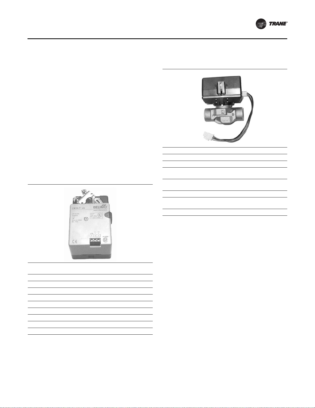
Modulating Water Valves (Option). The modulating
control valve option provides optimum control of hot and
chilled water flow in various heating and cooling
applications. They are designed to provide sinusoidal
valve actuator travel and operate silently, resisting water
hammer.
The actuator on the valve is a 24V, 3-point floating type.
See Ta b l e 3 , p . 9 for more technical data.
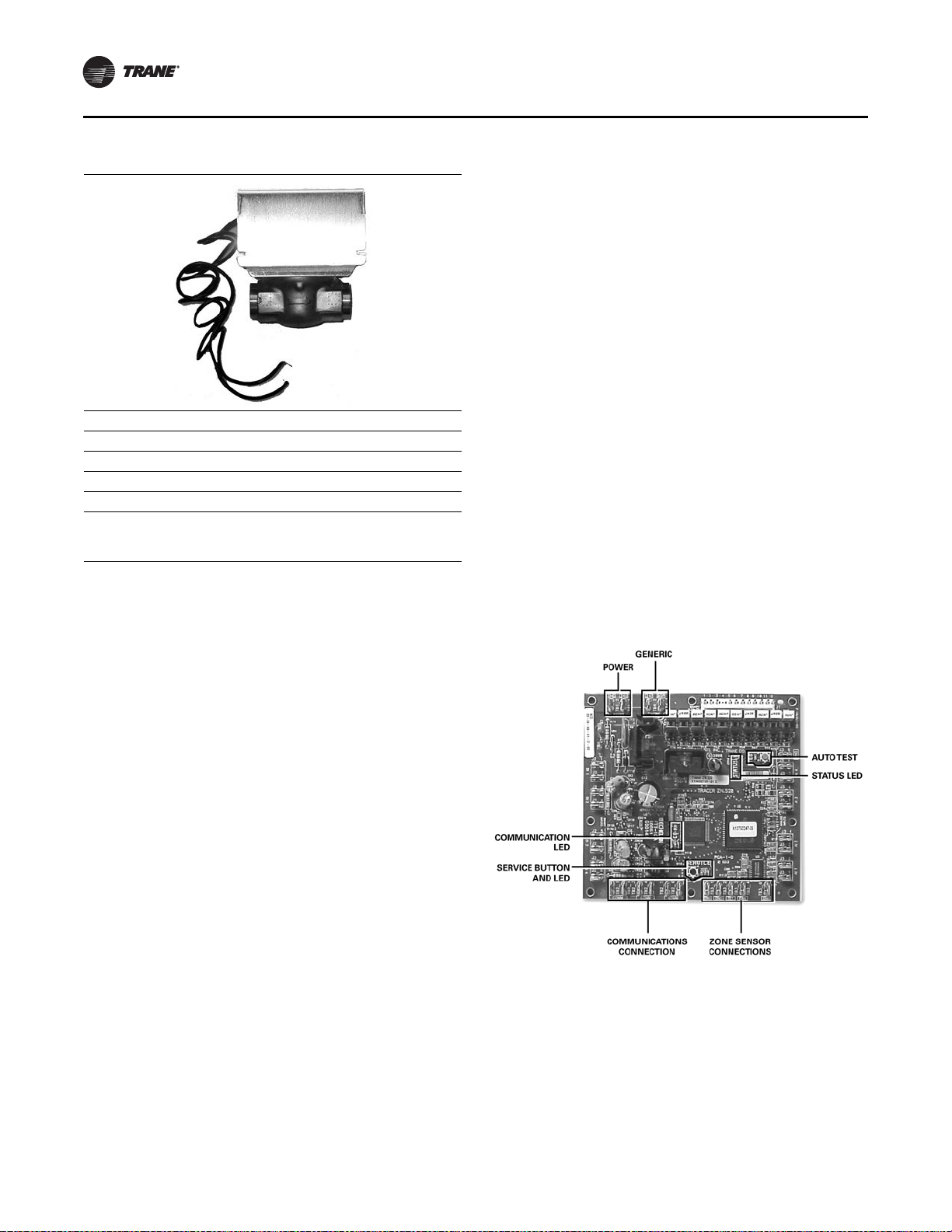
Isolation Valves (Option). The isolation valves are two
position 24V, spring return type. They provide added
control in heating and cooling applications when used in
conjunction with the face and bypass damper.
On heating coils and two-pipe change-over applications,
the valve is a normally open type to prevent the coil from
freezing in case of power loss.
For cooling, the valve is normally closed and opens when
there is a call for cooling. See Table 4, p. 10 for more
technical data.
Table 2. Technical data for face and bypass actuator
Power Supply 24 Vac ±20% 50/60Hz
24 Vac ±10%
Power Consumption 2W
Transformer Sizing 3VA (class 2 power source)
Manual Override External push button
Control Signal 3-point floating w/Trane controls
Rotation Angle 95-degree max. Adjustable w/mechanical stop
Torque 35-inch/lb
Rotation Direction Reversible with switch L/R
Position Indication Clip-on indicator
Noise Level Less than 35dB
Table 3. Technical data for modulating water valves
Power Supply 24V - 50/60 Hz
Power Consumption 4W
Maximum Duty Cycle 15%
Operating Ambient Temperature 0°C to 65°C
32°F to 150°F
Min./Max. Fluid Temperatures 1°C to 95°C
34°F to 203°F
Operating Pressure Differential Max. - 4 bar (60 psi)
Pressure Rating Static - 20 bar (300 psi)
Burst - 100 bar (1500 psi)
Flow Characteristics Linear
General Information
10 UV-SVN02C-EN
Unit Ventilator Controls
Options
Field-Installed Controls (Option). The unit comes
equipped with a fan speed switch, damper blade (only),
and an optional low temperature detection.
Customer Supplied Terminal Interface (CSTI)
(Option).
Units containing the end device control design
will incorporate a pre-wired, selected control components
to a terminal strip for wiring a field-provided controller and
temperature sensor.
Note: For controller operation malfunction of any non-
Trane, field installed controls, consult the literature
or technical support of the controls manufacturer.
Tracer ZN520 Control Package (Option). The Tracer
ZN520 electronic digital controller is a factory installed,
tested and commissioned LonTalk
®
certified design. It
may be used in a stand-alone control scheme, or as part of
a building automation system. The controller is pre-wired
to Trane selected control components best suited for room
comfort. For more information on the Tracer ZN520 unit
controller operation and service issues, refer to
CNT-SVX04A-EN (Installation, Operation, and
Programming Guide: Tracer ZN520 Unit Controller), or the
most recent version.
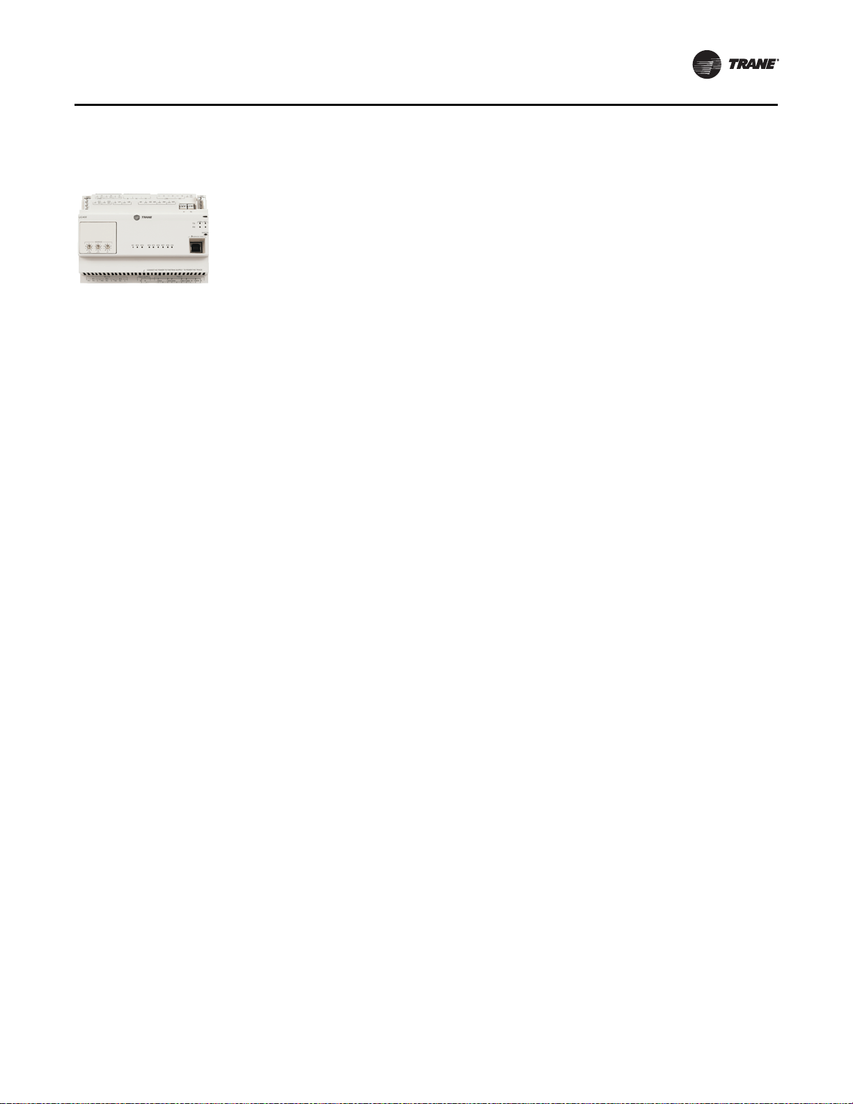
Tracer UC400 Control Package (Option). The Tracer
UC400 electronic digital controller is a factory installed,
tested and commissioned BACnet
®
certified design. The
Tracer UC400 operates as a single zone VAV controller and
ramps fan speed based on space load. It may be used in a
stand-alone control scheme, or as part of a building
automation system. The controller is mounted, pre-wired,
and pre-programmed to selected control components
best suited for room comfort. For more information on the
Tracer UC400 unit controller operation and service issues,
refer to BAS-SVX48B-EN (Installation, Operation, and
Table 4. Technical data for isolation water valves
Power Supply 24V - 50/60 Hz
Power Consumption 5W
Max. Fluid Temp. 200°F / 94°C
Min. Fluid Temp. 34°F / 1°C
Max. Operating Pressure 300 psi
Max. Close-off Pressure 1/2 in.= 30 psi
3/4 = 20 psi
1 = 15 psi
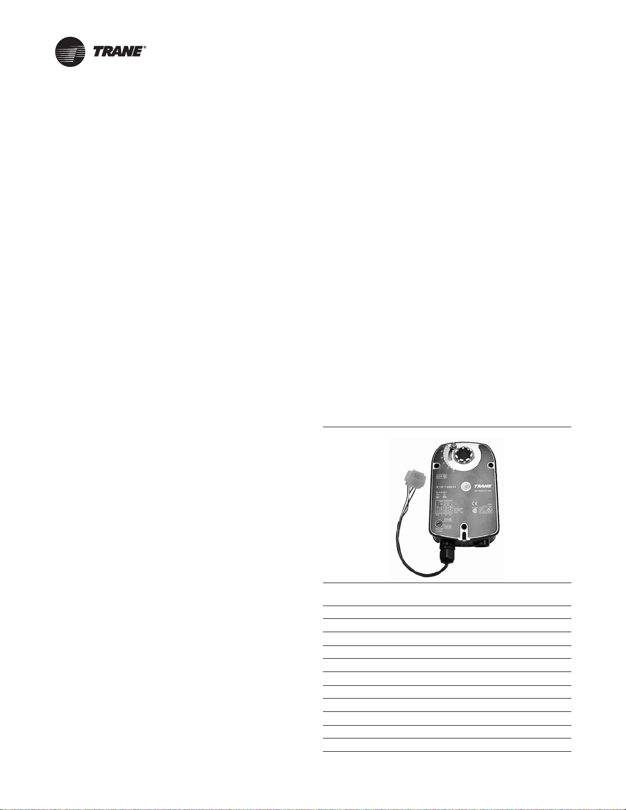
Figure 1. Tracer ZN520 unit controller
General Information
UV-SVN02C-EN 11
Programming: Tracer UC400 Programmable Controller),
or the most recent version.
When Trane controls are ordered for an installation, the
controls are shipped already installed and factory-tested
to ensure proper operation at start-up.
Notes:
• For more details on the ZN520 unit controller option or
operation and service/replacement issues, please refer
to CNT-SVX04A-EN (Installation, Operation, and
Programming Guide: Tracer ZN520 Unit Controller), or
the most recent version.
• For more details on the UC400 unit controller option or
operation and service/replacement issues, refer to
BAS-SVX48B-EN (Installation, Operation, and
Programming: Tracer UC400 Programmable
Controller), or the most recent revision.
Automatic Controls
Regardless of type of controls, all systems provide a
sequence of operation designed to provide rapid warm-up
of the room and increase ventilation while offsetting
overheating.
In addition, air conditioning installations will usually
provide a means of system changeover from heating to
cooling as well as provisions for drawing a pr e-determined
amount of outside air into the room.
Unit Switch
The unit “On-Off” switch, provided by Trane, is typically
housed in the control box mounted in the left hand end
pocket immediately below the discharge grille.
When Tracer ZN520 or Tracer UC400 unit controllers are
used, the unit switch is located on the switch module in the
end pocket behind the front panel rather than below the
grille.
Figure 2. Tracer UC400 unit controller
12 UV-SVN02C-EN
ECM Application Notes
The new Trane BLDC system has some notable differences
to traditional designs.
RPM Mode
The motors are programmed from the factory to run in
rpm mode and will not change rpm based on external
static pressure, except at the performance limits of the
motor/controller. For ducted units, the units are shipped
with the rpm set for 0.2 in. ESP for High, Medium, and Low
speeds. The speeds can for high, medium, and low
operation, but should not be changed for the electric heat
actuation speeds.
Generally, the fans deliver less cfm for the same rpm, if the
static is increased and the power will decrease. The fan will
deliver more cfm for the same rpm, if the static is
decreased and the fan power will increase. A unit with high
static configuration should not be used to free-deliver air
(i.e., with no ducting attached).
Field Power Wiring
Note: This product uses an electronic variable speed
motor control, which includes a line reactor to
minimize power line harmonic currents. It is
recommended that good wiring practices be
followed to manage building electrical power
system harmonic voltages and currents to avoid
electrical system problems or other equipment
interaction.
Performance Boundaries
While the speeds of the fan motors can be adjusted, never
program a fan speed higher than 1700 rpm, or lower than
450 rpm. In many cases, units configured for high-static
operation will not achieve the desired rpm if the ESP of the
unit is too low, or the unit is allowed to “free-discharge.”
The ECM engine contains settings that will limit the output
power of the motor under these overload conditions. If the
motors cannot achieve rpm close to the target for a specific
period of time, the unit will disable electric heat and fan-
status indicators.
MCA/MFS and Power Draw
The Trane BLDC motors have variable output but are
shipped at specific settings to deliver proper performance
and reliability. The power draw indicated in the catalogue
indicates the power consumed when applied properly (as
shipped and with the nominal ESP applied). However, the
nameplate of the unit indicates the maximum input draw
of the motor, as the motor settings can be changed to draw
more power.
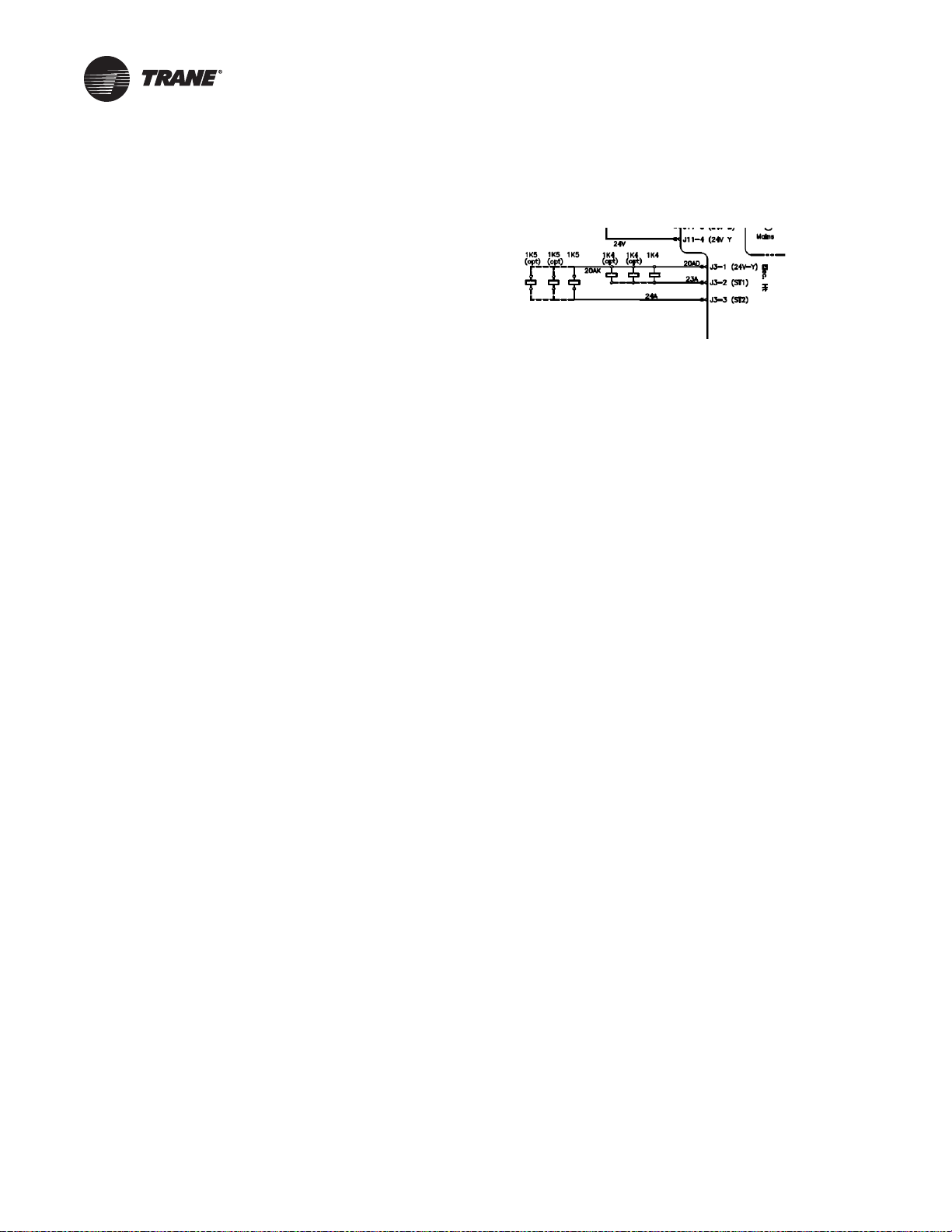
Electric Heat Relays
For quiet operation, the new BLDC units employ power
relays instead of definite purpose contactors for electric
heat actuation. The coils of multiple relays are hooked in
parallel to simulate a multi-pole contactor, as shown in
Figure 3. In Figure 3, two sets of three relays are used to
perform the function of a two 3-pole contactors.
Troubleshooting Other Unit Functions
In some cases, the normal or abnormal operation of the
BLDC system may interact with other components in the
system. Generally, verification of the engine and adapter
boards’ wiring and configuration should be checked if
there are unexplained abnormalities in other areas of the
unit:
1. Valve operation
2. Electric Heat operation
3. Changeover sensor operation
4. Damper operation
5. Condensate overflow switch
A high degree of protection is provided on electric heat
u
nits. If electric heat fails to actuate, it may be because of
one of the following events:
1. Fans are failing to meet target speed. If a second motor
is not present, all settings for speeds for Motor 2
should be set to 0000.
2. Hot water may be available in the changeover coil.
3. The connection to analogue input 1 on the Tracer ZN
controlle
r may be reversed in polarity.
4. Target speeds for motor
s may be set too high:
a. The parameter may be set incorrectly.
b. The
parameter may be set incorrectly.
Figure 3. Sample arrangement: electric heat relay

UV-SVN02C-EN 13
Dimensions and Weights
Unit Location and Clearances
Locate the unit in an indoor area. The ambient
temperature surrounding the unit must not be less than
45°F. Do not locate the unit in areas subject to freezing.
Attention should be given to service clearance and
technician safety. The unit should contain enough space
for service personnel to perform maintenance or repair.
Provide sufficient room to make water, and electrical
connection(s).
A 36-inch clearance at the unit front is sufficient for
maintenance and service of the equipment.
NOTICE:
Equipment Damage!
Do not locate the unit in areas subject to freezing. Pipes
could burst at lower temperature resulting in
equipment damage.
WARNING
Electrocution and Fire Hazards with
Improperly Installed and Grounded Field
Wiring!
Improperly installed and grounded field wiring poses
FIRE & ELECTROCUTION hazards. To avoid these
hazards, you MUST follow requirements for field wiring
installation and grounding as described in NEC and
your local/state electrical codes. All field wiring MUST
be performed by qualified personnel.
Failure to follow these requirements could result in
death or serious injury.
Table 5. Weights and measurements: horizontal unit ventilators
Unit Size 075 100 125 150 200
Unit Length (in.) 70-1/4 82-1/4 94-1/4 106-1/4 106-1/4
Unit Height (in.) 16-5/8 16-5/8 16-5/8 16-5/8 17-5/8
Unit Width (Front Discharge) (in.) 35-5/8 35-5/8 35-5/8 35-5/8 43-1/8
Unit Width (Bottom Discharge) (in.) 48-3/4 48-3/4 48-3/4 48-3/4 57-1/4
Shipping Weight (lb)
(a)
340* 375* 435* 500* 600*
Filter Size (inches-actual) 41-1/2 x 15-1/4 x 1 53-1/2 x 15-1/4 x 1 65-1/2 x 15-1/4 x 1 77-1/2 x 15-1/4 x 1 77-1/2 x 15-1/4 x 1
(a) Working weight is approximately 10% less than shipping weight. Trane recommends 1/4-inch rods for hanging suspension
Table 6. Control methodology
Fan Speed
FSS 3 or infinite
(a)
(a)With a field-supplied 2–10 Vdc controller.
CSTI 3 or infinite
(a)
Tracer ZN520 3
Tracer UC400 Infinite
Table 7. Control sequences
Fan Speeds
DX operation
(a)
(a) Fan speed during sequence operation.
1
Electric heat operation
(a)
1
Sidewall Exhaust
(b)
(b)Unit Ventilator when operating with option.
2
ERSA
(b)
2

Dimensions and Weights
14 UV-SVN02C-EN
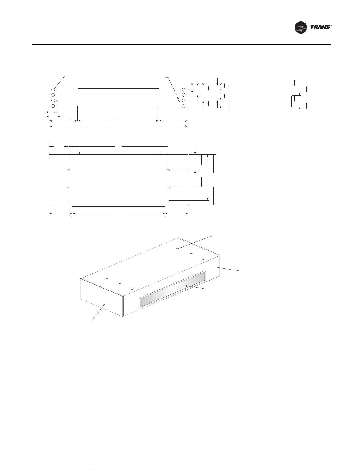
Figure 4. Horizontal unit ventilator with ducted front discharge dimensional data; sizes 075–150 (dimensions in
inches)
3"
4"
4"
1 3/4"
10 1/8"
6 1/2"
10 1/2"
32 1/2"
35 5/8"
11"
14 1/2"
16 5/8"
7 1/8"
7 7/8"
B17 1/8"
12 1/8"
13 1/2" 13 1/2"
4 7/8"
2 3/8"
2"-DIA K.O.
FOR PIPING
7/8"-DIA K.O.
FOR ELECTRICAL
17 1/8"
A
C
D
F.A. UPPER BACK
R.A. LOWER BACK
BACK VIEW SIDE VIEW
TOP VIEW
NOTE:
WHEN ELECTRIC HEAT IS PRESENT, ALL POWER
CONNECTIONS ARE MADE IN THE RIGHT HAND
END POCKET. ON ALL OTHER CONFIGURATIONS,
POWER CONNECTIONS ARE MADE IN THE LEFT
HAND END POCKET.
ISO VIEW
7/8" x 2" SLOTS
FOR HANGING BRACKETS
RIGHT HAND
END POCKET
LEFT HAND
END POCKET
DISCHARGE
Size A B C D
75 70-1/4 36 46 43-1/4
100 82-1/4 48 58 55-1/4
125 94-1/4 60 70 67-1/4
150 106-1/4 72 82 79-1/4
Dimensions and Weights
UV-SVN02C-EN 15
Figure 5. Horizontal unit ventilator with ducted front discharge dimensional data; size 200 (dimensions in inches)
4"
5"
5"
2 3/4"
10 1/8"
7 1/2"
11 1/2"
39 1/2"
26 1/2"
43 1/8"
13 1/2"
15 1/2"
17 5/8"
6 1/8"
9 7/8"
72"17 1/8"
12 1/8"
13 1/2" 13 1/2"
4 7/8"
2 3/8"
2"-DIA K.O.
FOR PIPING
7/8"-DIA K.O.
FOR ELECTRICAL
17 1/8"
106 1/4"
82"
79 1/4"
F.A. UPPER BACK
R.A. LOWER BACK
BACK VIEW SIDE VIEW
TOP VIEW
ISO VIEW
7/8" x 2" SLOTS
FOR HANGING BRACKETS
RIGHT HAND
END POCKET
LEFT HAND
END POCKET
DISCHARGE
NOTE:
WHEN ELECTRIC HEAT IS PRESENT, ALL POWER
CONNECTIONS ARE MADE IN THE RIGHT HAND
END POCKET. ON ALL OTHER CONFIGURATIONS,
POWER CONNECTIONS ARE MADE IN THE LEFT
HAND END POCKET.
72"
Dimensions and Weights
16 UV-SVN02C-EN
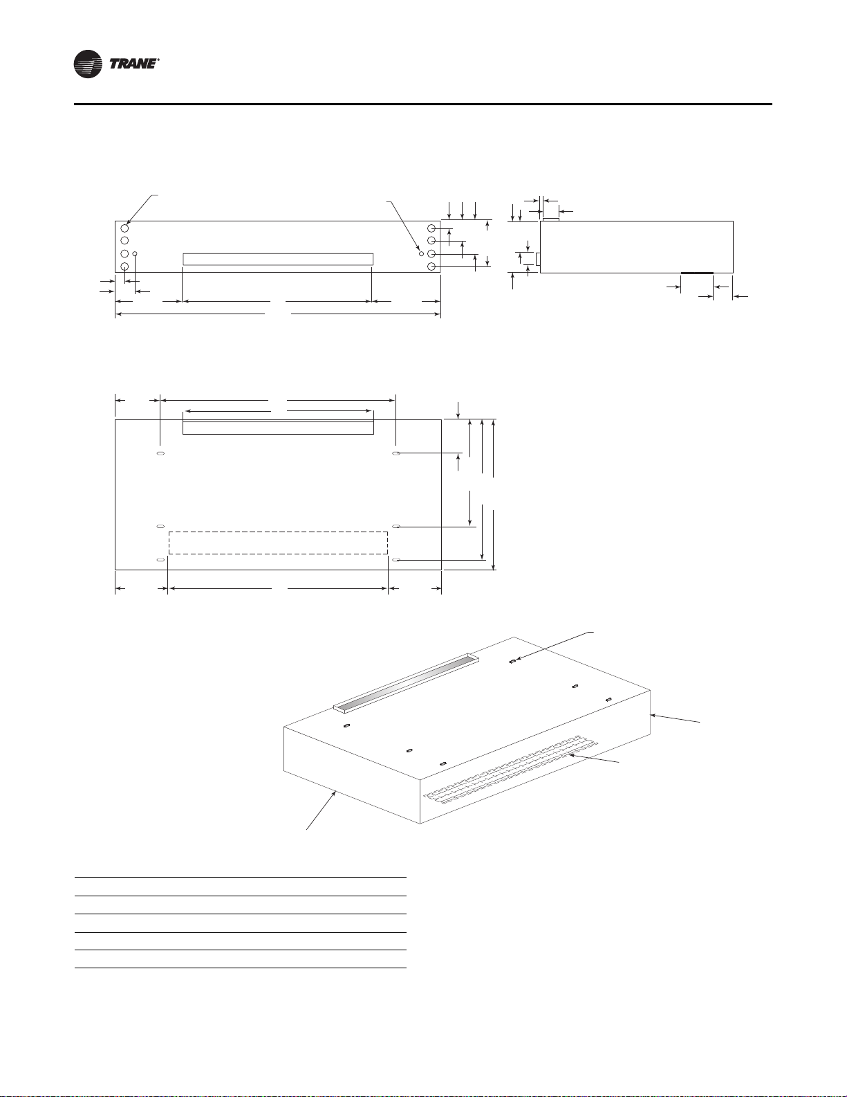
Figure 6. Horizontal unit ventilator with double deflection discharge dimensional data; sizes 075–150 (dimensions in
inches)
3"
6 1/2"
10 1/2"
14 1/2"
B
R.A. LOWER BACK
17 1/8"
4 7/8"
2 3/8"
2"-DIA K.O.
FOR PIPING
7/8"-DIA K.O.
FOR ELECTRICAL
17 1/8"
3/4"
7 1/4"
5 1/8"
4"
A
4"
16 5/8"
10 1/8"
32 3/4"
46"
48 3/4"
11"
12 1/8"
13 1/2" 13 1/2"
C
D
BACK VIEW SIDE VIEW
TOP VIEW
NOTE:
WHEN ELECTRIC HEAT IS PRESENT, ALL POWER
CONNECTIONS ARE MADE IN THE RIGHT HAND
END POCKET. ON ALL OTHER CONFIGURATIONS,
POWER CONNECTIONS ARE MADE IN THE LEFT
HAND END POCKET.
ISO VIEW
7/8" x 2" SLOTS
FOR HANGING BRACKETS
RIGHT HAND
END POCKET
LEFT HAND
END POCKET
BOTTOM DISCHARGE
B
Size A B C D
75 70-1/4 36 46 43-1/4
100 82-1/4 48 58 55-1/4
125 94-1/4 60 70 67-1/4
150 106-1/4 72 82 79-1/4
Dimensions and Weights
UV-SVN02C-EN 17
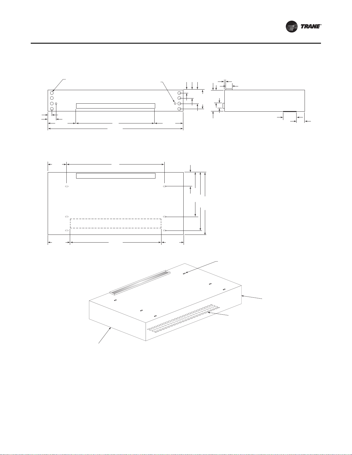
Figure 7. Horizontal unit ventilator with double deflection discharge dimensional data; size 200 (dimensions in
inches)
4"
7 1/2"
11 1/2"
15 1/2"
72"
R.A. LOWER BACK
17 1/8"
4 7/8"
2 3/8"
2"-DIA K.O.
FOR PIPING
7/8"-DIA K.O.
FOR ELECTRICAL
17 1/8"
3/4"
9 1/4"
5 1/8"
5"
106 1/4"
5"
17 5/8"
10 1/8"
26 1/2"
53 3/4"
57 1/4"
13 1/2"
12 1/8"
13 1/2" 13 1/2"
82"
79 1/4"
BACK VIEW SIDE VIEW
TOP VIEW
ISO VIEW
7/8" x 2" SLOTS
FOR HANGING BRACKETS
RIGHT HAND
END POCKET
LEFT HAND
END POCKET
NOTE:
WHEN ELECTRIC HEAT IS PRESENT, ALL POWER
CONNECTIONS ARE MADE IN THE RIGHT HAND
END POCKET. ON ALL OTHER CONFIGURATIONS,
POWER CONNECTIONS ARE MADE IN THE LEFT
HAND END POCKET.
BOTTOM DISCHARGE
Dimensions and Weights
18 UV-SVN02C-EN
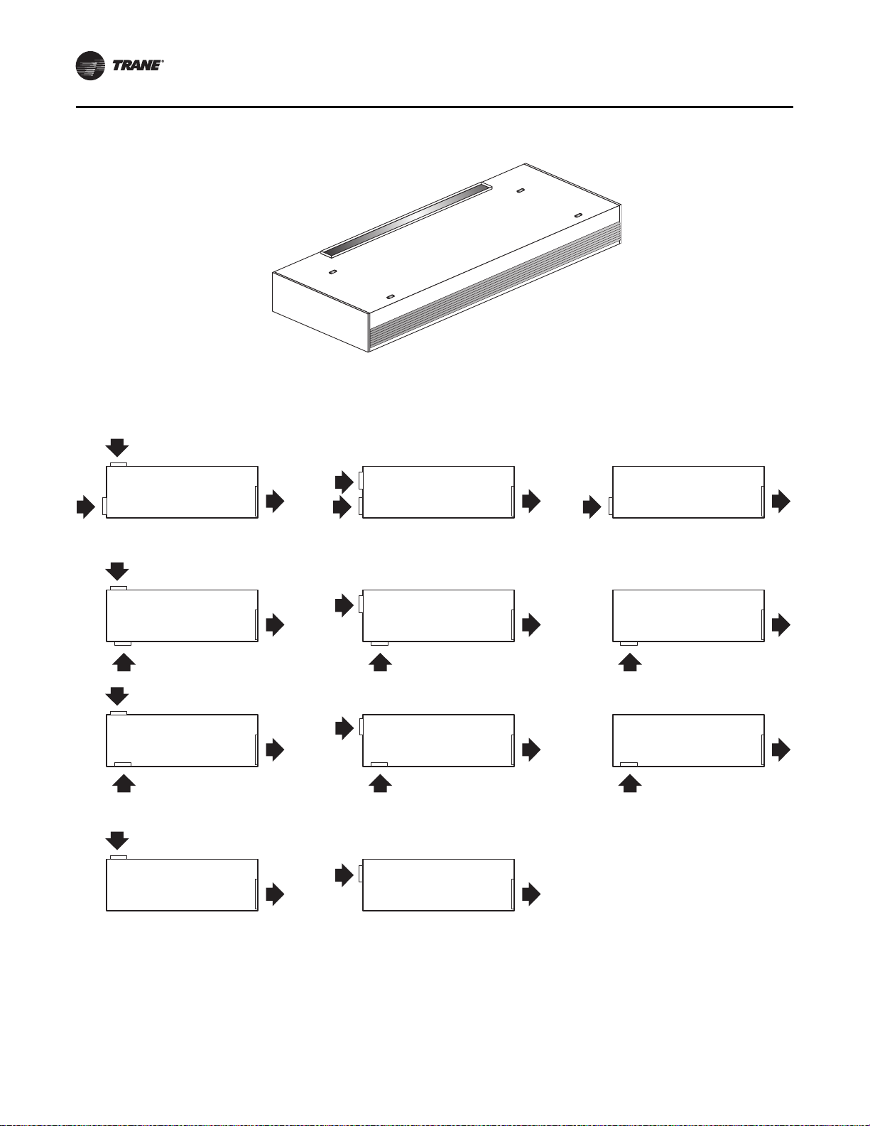
Figure 8. Supply/return air arrangements for the horizontal unit ventilator
DIGIT 20 = A
FA DUCT TOP
w/RA DUCT LOWER BACK
DIGIT 20 = B
FA DUCT TOP
w/RA DUCT BOTTOM
DIGIT 20 = G
FA DUCT UPPER BACK
w/RA DUCT BOTTOM
DIGIT 20 = F
FA DUCT UPPER BACK
w/RA DUCT LOWER BACK
DIGIT 20 = E
100% FA DUCT TOP
DIGIT 20 = K
100% FA DUCT UPPER BACK
DIGIT 20 = C & D
(C) FA DUCT TOP
w/RA BAR GRILLE BOTTOM
(D) FA DUCT TOP
w/RA OPEN BOTTOM
DIGIT 20 = H & J
(H) FA DUCT UPPER BACK
w/RA BAR GRILLE BOTTOM
(J) FA DUCT UPPER BACK
w/RA OPEN BOTTOM (no grille)
DIGIT 20 = M
100% RA DUCT BOTTOM
DIGIT 20 = L
100% RA DUCT LOWER BACK
DIGIT 20 = N & P
(N) 100% RA BAR GRILL BOTTOM
(P) 100% RA OPEN BOTTOM
(no grille)
UV-SVN02C-EN 19
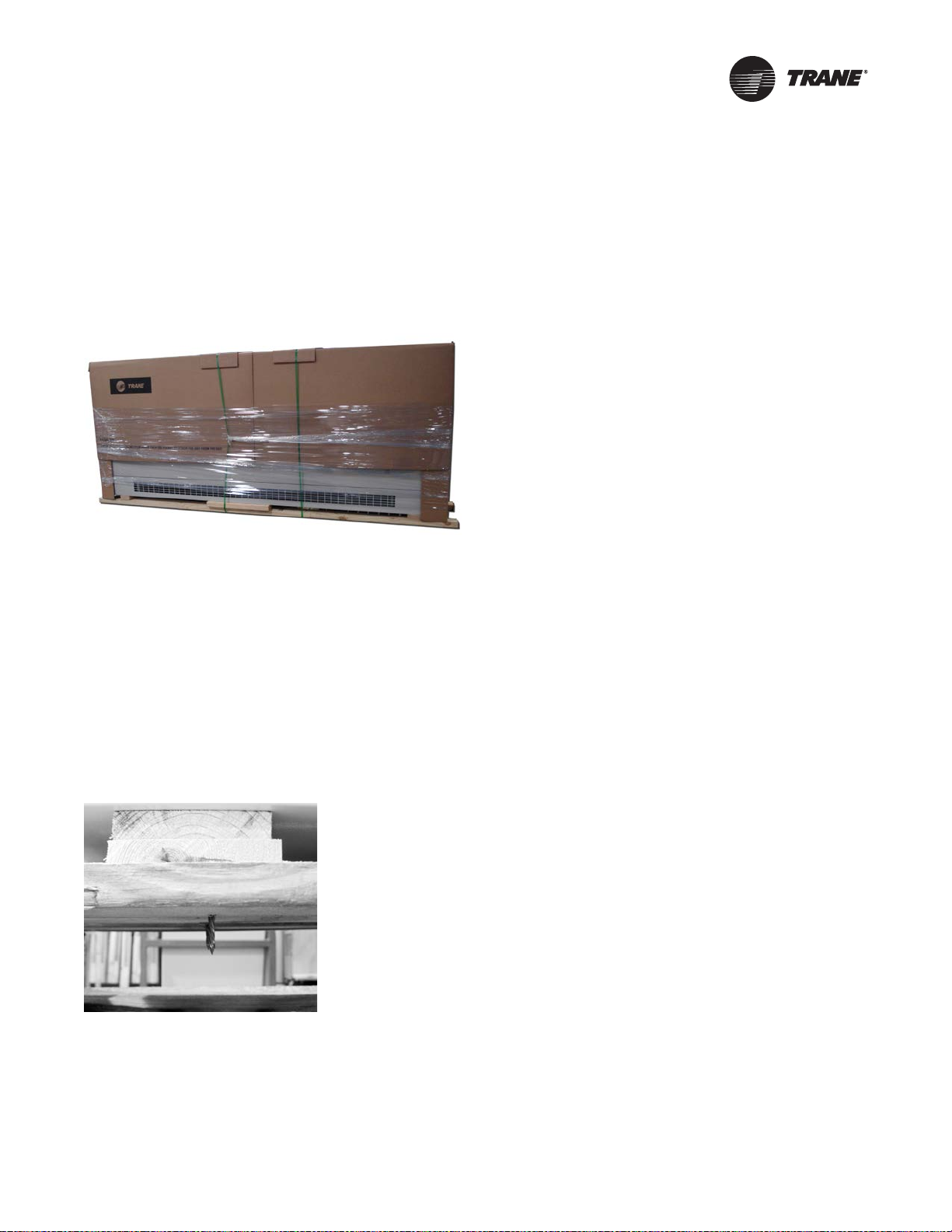
Receiving and Handling
The unit ventilator is packaged in clear stretch wrap and
protective cardboard.
Note: Before unwrapping, make a visual inspection of the
unit for any damage that may have occurred during
shipping. All orders are shipped FOB (Freight on
Board) from the factory, therefore any claims must
be made with the delivering carrier.
Following visual inspection, carefully begin the following
procedures:
1. Carefully remove the stretch wrap and the top
cardboard cover.
2. Remove remaining cardboard blocking.
3. Remove the bottom access panel with a 7/32-in. Allen
wrenc
h.
4. Verify nameplate sales order number is correct.
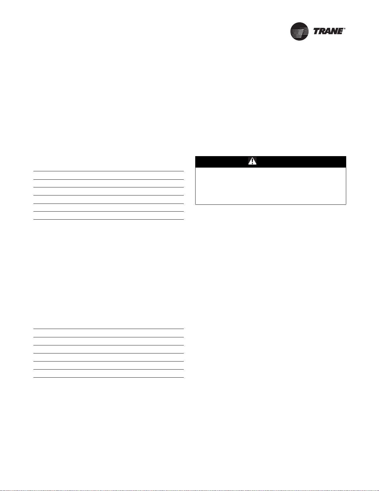
5. Remove shipping bracket from the lower rear corners
of the unit and shipping skid. Access to the screws
holding unit to the skid is obtained inside the unit.
6. Rotate fan wheels manually. Wheels should move
freely and be in proper alignment. Visually inspect the
fan area for obstructions or shipping damage.
7. Remove all applicable knock-outs for coil piping and
electrical connections
(see Figure 5, p. 13 through
Figure 7, p . 17).
Figure 9. Horizontal unit ventilator as shipped
Figure 10. Shipping skid removal
20 UV-SVN02C-EN
Pre-Installation
Jobsite Inspection
Always perform the following checks before accepting a
unit:
1. Verify that the nameplate data matches the data on the
sales order and bill of lading (including electrical data).
2. Verify that the power supply complies with the unit
nameplate specifications.
3. Visually inspect the exterior
of the unit, for signs of
shipping damage. Do not sign the bill of lading
accepting the unit(s) until inspection has been
completed. Check for damage promptly after the
unit(s) are unloaded. Once the bill of lading is signed at
the jobsite, the unit(s) are now the property of the
SOLD TO party and future freight claims MAY NOT be
accepted by the freight company.
Jobsite Storage
This unit is intended for indoor use only. To protect the unit
from damage due to the elements, and to prevent possible
IAQ contaminant sources from growing.
1. Place the unit(s) on a dry surface or raise above the
ground to assure adequate air circulation beneath the
unit.
2. Cover the unit(s) with a water proof tarp to protect
them
from the elements.
3. Make provisions for continuous venting of the covered
units to prevent moisture from standing on the unit(s)
surfaces.
4. Do not stack units.
NOTICE:
Microbial Growth!
Wet interior unit insulation can become an
amplification site for microbial growth (mold), which
may cause odors and damage to the equipment and
building materials. If there is evidence of microbial
growth on the interior insulation, the insulation should
be removed and replaced prior to operating the system.
UV-SVN02C-EN 21
Installation—Mechanical
Location Considerations
Selecting the appropriate location for installing a unit is
very important. The following factors should be
considered:
1. Ceiling hung design must be of sufficient structure to
support the weight of the unit (see Ta bl e 8 for weight
data). Figure 5, p. 13 through Figure 9, p. 17 show
hanging rod location and placement.
Note: Isolator and suspension rods are to be provided
by the installer. For hanging suspension, Trane
recommends 3/8-in. rods.
2. Service access is gained through the access panels on
the bottom of the unit. Sufficient space should be
allowed for panel removal. If the hinged panel option
is ordered, allow for a swing radius of 14-in.
3. Sufficient free area around both the discharge and wall
b
ox should be maintained to ensure proper
ventilation. If any part of the discharge is blocked off,
unit performance may be affected. If the wall box is too
small on the inlet, water or debris could be pulled into
the unit (see Ta bl e 9) for minimum wall box free area
requirements).
4. Use the shortest and most efficient ductwork possible
when ducting the discharge and/or return air grille.
Units ordered with a duct collar discharge
arrangement are equipped with a 1-in. duct flange.
Note: Ductwork
for ducted units will be provided by
the installer.
5. If installing a split system, refe
r to the condenser
installation instructions provided with that unit for
special location considerations.
Note: M
easurements in Figure 5, p. 13 through
Figure 9, p. 17 do not include adjusted leveling
legs. Adjustment of Leveling legs should be
done first. New measurements from the floor
should be retaken before installation.
Unit Mounting
The horizontal unit ventilator may be attached directly to
the ceiling or suspended from the ceiling by hangers.
Hanger rods should be at least 3/8 in. diameter steel to
support unit weight, as given in Table 8, p. 21.
Install the hanging devices before hoisting the unit. A fork
lift or other special lifting device is required to hoist the
unit into mounting position.
Protect the unit finish by covering the lifting platform.
To hoist the unit into place, follow the instructions below:
1. Secure 2 x 4s to the lift forks. These two supports must
be long enough and spaced properly on the forks to
support the unit while it is being lifted and clear the
duct flanges on the unit.
2. Tip the unit onto the supports and slide it toward the lift
un
til the unit weight balances.
3. Lift the unit. Once in position, temporarily secure the
u
nit to the hanger rods or mounting studs with nuts
and washers.
4. Align the unit with the du
ct work. When in proper
alignment, tighten the mounting nuts securely.
5. Recheck the unit alignment and make sure the unit is
level
.
6. Replace all covers, panels and filters
before starting
the unit.
Note: Un
it must be mounted level. Coils and drain pans
inside unit are pitched properly for drainage before
shipment.
Horizontal Recessed Mounting
The recessing flange assembly ships in a box separate
from the unit. The assembly includes pre-cut flanges,
corner transition pieces, mounting screws, filler pieces,
and pressure sensitive gaskets. Refer to Figure 11 and
Figure 12, p. 22 for typical horizontal installation.
Ta b l e 8. Typical unit weights
(a)
(a) Weight at time of shipping. Subtract approximately 10% for actual
hanging weight.
Unit Size lb kg
075 340 154
100 375 170
120 435 197
150 500 227
200 600 272
Table 9. Wall box free area requirements
Unit Size Discharge (in
2
)Inlet (in
2
)
075 232 169
100 296 217
120 364 265
150 430 313
200 576 391
WARNI NG
Heavy Objects!
Always lift unit with fork trucks or other special lifting
device following the recommended procedures. Failure
to properly lift the unit as instructed, could result in
death or serious injury.
Installation—Mechanical
22 UV-SVN02C-EN
1. Measure and cut the pressure sensitive gaskets to the
correct lengths and attach to the flanges.
2. Starting at a corner, attach the top flange with the
mounting screws provided.
3. Press the corner transition pieces
onto the end of the
flange and attach the adjoining flanges and filler
pieces at the bottom of the unit. Work around the unit
in this manner until all flanges and corners are
installed.
4. Mounting holes are pre-drilled in
the flanges. Use the
assembled flanges as a template to drill all 7/32-in.
mounting holes in the cabinet.
5. Attach the flange section to
the unit cabinet with the
mounting screws provided.
6. Open and remove the front access panel.
7. Tighten the mounting fastener
, making sure that the
unit is level.
8. Open the unit access panel and remove the bottom
front panel
(see Figure 13, p. 22).
9. Hoist the unit onto a forklift and mount in place as
described in “Unit Mounting,” p. 21, ensuring the unit
is secured and aligned in place, and that the mounting
nuts
are tightly fastened.
Note: Un
it must be mounted level. Coils and drain
pans inside the unit are pitched internally for
proper drainage.
10. Replace all covers, panels and filters before starting the
un
it.
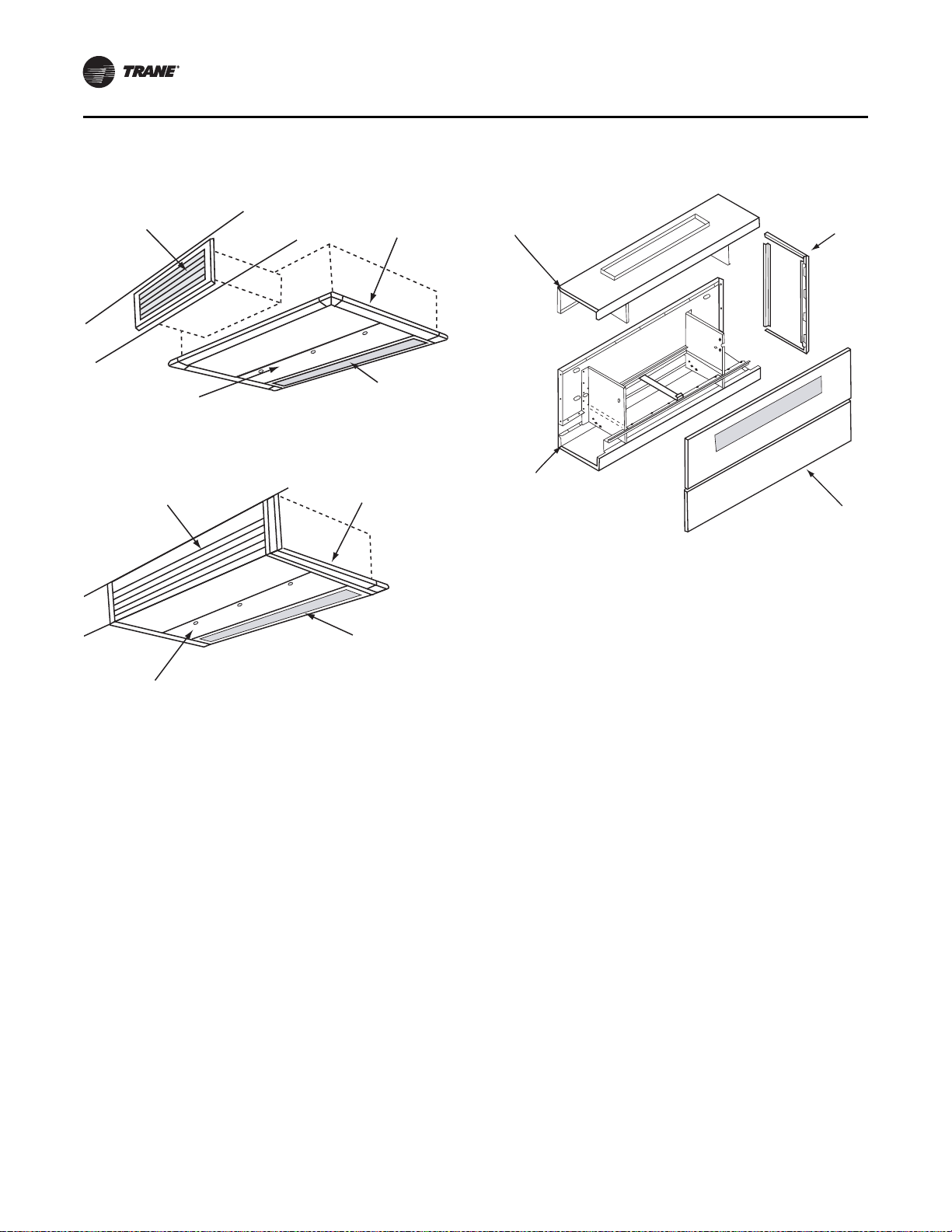
Figure 11. Recess flange installation around horizontal
unit ventilator access panel and inlet
Figure 12. Recess flange installation around bottom
and front of horizontal unit
Supply
Air
G
rille
Access Panel
Recessing Flange
Return Air
Inlet Grille
Supply Air
Grille
Access Panel
Recessing Flange
Return Air
Inlet Grille
Figure 13. Horizontal unit ventilator with front panel
removed
Intake Panel
Bottom Front Panel
Discharge Panel
End Cover
UV-SVN02C-EN 23
Installation—Piping
Note: Before installation of piping package, the shipping
bracket holding the piping in place, must be
removed.
Proper installation of piping is necessary to provide
efficient coil operation and to prevent damage during
operation. Follow standard piping practices and include all
accessories as necessary.
Piping connection knockouts are shown in Figure 5, p. 13
through Figure 9, p. 17. Field connection types and sizes
for units without piping packages are listed in Tab l e 10 ,
p. 23.
A 3/4-in. OD condensate drain connection is provided on
the chilled water supply end of the unit. Attach a flexible
condensate drain hose over the drain pan connection and
secure with a hose clamp.
The drain pan on the horizontal unit is internally pitched.
To field reverse, remove the screws and drain pan, rotate
the pan and reinstall.
After the condensate drain piping has been completed,
check water flow to be sure the system properly carries and
away all condensate accumulation.
A P-trap is recommended for installations that drain
directly into a sewer system. A P-trap is not necessary for
operation but will eliminate sewer gas odor.
Trane Piping Packages (Option)
Trane Standard Piping Package includes a two- or three-
way valve with bypass balance valve, ball valves, Pete’s
plugs, and unions. A strainer and circuit balancing valve
are optional.
All union connections should be tightened in the field.
Units are shipped with union connections hand-tightened
only in the factory.
Notes:
• All connections made in the field should be sweat
connections.
• Piping packages are not shipped insulated. Any
insulation should be provided in the field by the
installing contractor.
Split System Units
The following refrigerant piping and interconnecting
wiring instructions apply to unit ventilators with direct
expansion type cooling coils used in conjunction with air-
cooled condensing units. Reference must also be made to
the condensing unit installation and wiring manuals which
are shipped with the condensing unit.
Note: A UL listing mark applied to a unit ventilator does
not apply to any associated refrigerant condensing
unit.
Refrigerant Piping
Unit ventilators with direct expansion cooling are
dehydrated and shipped with a dry air holding charge.
Connections are “pinched off” at the factory.
To connect the condensing unit lines, cut off the stubouts
and swage. The condensing unit lines can then be brought
into the swage and brazed. Trane recommends the use of
nitrogen purge when brazing refrigerant lines to prevent
formation of oxides in the lines.
Table 10. Coil data for field piping
Coil Type Connection Location Field Connection Size
4-pipe chilled water /
hot water
Left or right (opposite
ends)
7/8 in. OD / 5/8 in. OD
2-pipe changeover coil Left or right 7/8 in. OD
Hot water only Left or right 7/8 in. OD
Steam Left or right 1 in. MPT
Chilled water / electric
heat
Left cooling 7/8 in. OD
Chilled water / steam Left or right 7/8 in. OD / 1 in. MPT
DX Left 7/8 in. suction, 3/8 in.
DX / hot water Left cooling / right
heating
7/8 in. suction,
3/8 in. / 5/8 in. OD
DX / steam Left cooling / right
heating
7/8 in. suction,
3/8 in. / 1 in. MPT
DX / electric heat Left cooling / right
heating
7/8 in. suction,
3/8 in. / NA
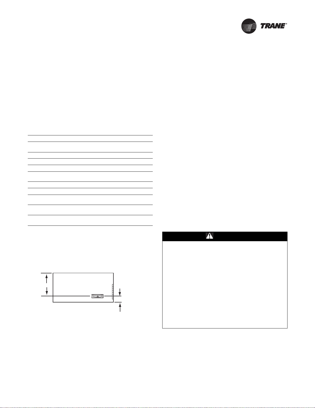
Figure 14. Condensate drain pan location
13-5/8"
3"
Horizontal Unit
WARNING
Hazard of Explosion and Deadly Gases!
Never solder, braze or weld on refrigerant lines or any
unit components that are above atmospheric pressure
or where refrigerant may be present. Always remove
refrigerant by following the guidelines established by
the EPA Federal Clean Air Act or other state or local
codes as appropriate. After refrigerant removal, use dry
nitrogen to bring system back to atmospheric pressure
before opening system for repairs. Mixtures of
refrigerants and air under pressure may become
combustible in the presence of an ignition source
leading to an explosion. Excessive heat from soldering,
brazing or welding with refrigerant vapors present can
form highly toxic gases and extremely corrosive acids.
Failure to follow all proper safe refrigerant handling
practices could result in death or serious injury.
Installation—Piping
24 UV-SVN02C-EN
Install the refrigerant suction and liquid lines as described
in the condensing unit installation instructions. The
thermal expansion valve (TXV) is factory-installed on the
Unit Ventilator.
Note: The R-410A direct expansion (DX) refrigerant coil
includes a factory-mounted adjustable thermal
expansion valve (TXV) set to 90 psig superheat and
an equalizing tube.
Piping should be run straight out through the back of the
unit. Access piping knockouts are located in the rear
panels of the unit, as shown in Figure 5, p. 13 through
Figure 9, p. 17.
Recommended refrigerant line connections for various
unit combinations are given in Table 9, p. 21. Typical
Superheat Charging Charts are shown in the Trane Service
Facts found in the condensing unit section manual.
Refrigerant charge weights can also be determined with
your local Trane account manager using a valid Trane
Selection Program.
Steam Piping
When air, water or another product is heated, the
temperature or heat transfer rate can be regulated by a
modulating steam pressure control valve. Since pressure
and temperature do not vary at the same rate as load, the
steam trap capacity, which is determined by the pressure
differential between the trap inlet and outlet, may be
adequate at full load, but not some lesser load.
There are detailed methods for determining condensate
load under various operating conditions. However, in
most cases this is not necessary if the coils are piped as
shown in Figure 15. Follow the procedure documented in
the ASHRAE Systems Handbook, Steam Systems.
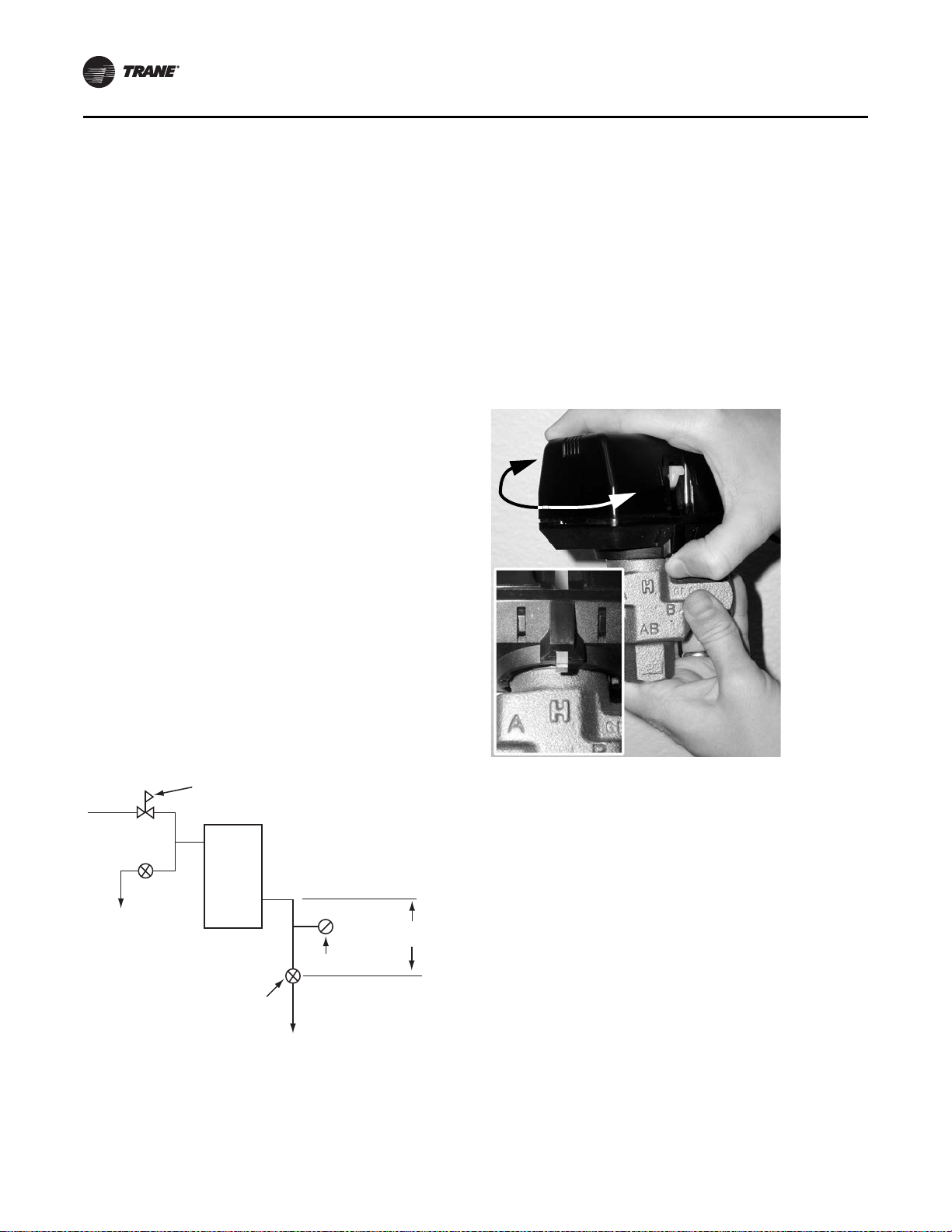
Modulating Water Valves (Option)
The actuator on the valve is a 24 V, three-point floating
valve. The actuator can be easily removed from the valve
body by pressing in on the locking tab and rotating the
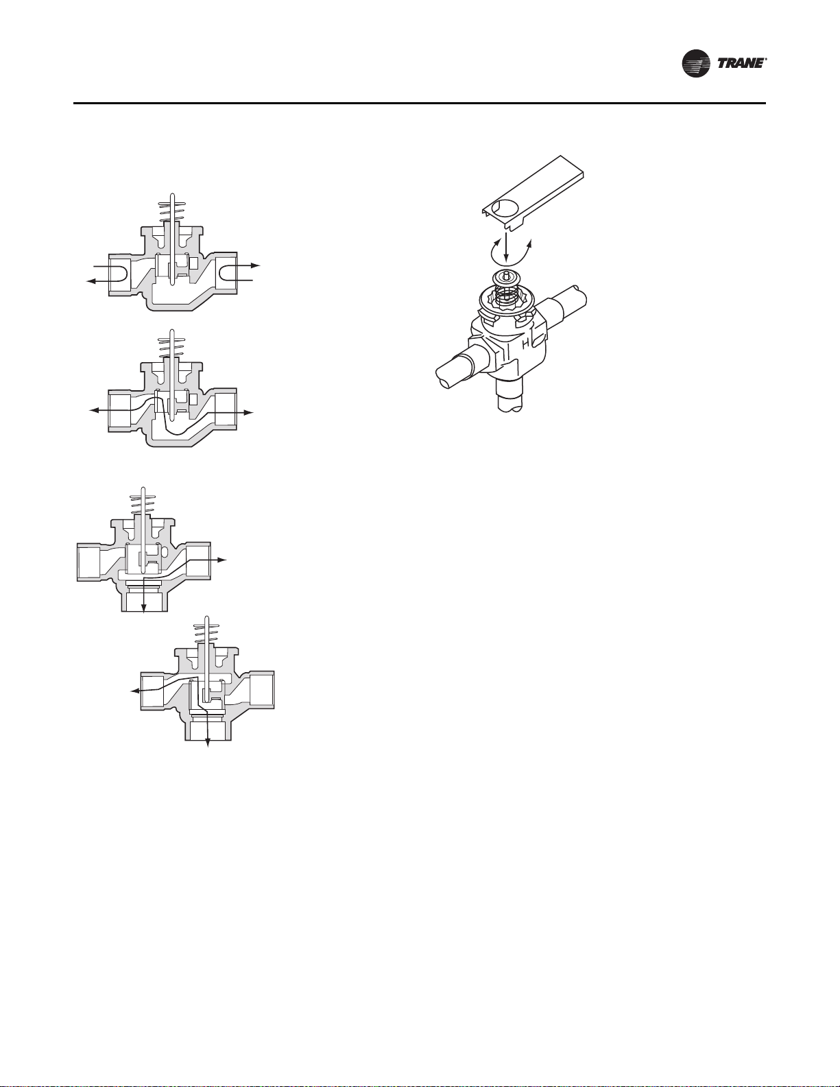
actuator 45° counter-clockwise (see Figure 16). The two-
way valves are bi-directional flow. The three-way valves
can be mixing or diverting (see Figure 17).
Note: The actuator must be removed if soldering is being
conducted near the valve. High heat may cause
damage to the actuator’s plastic body/
mechanisms.
On applications without factory-installed piping packages
(option), it is important to remove the cartridge assembly
from the valve body with the provided tool (see Figure 18,
p. 25).
Figure 15. Steam piping
Vacuum Equalizer
H= 12"
minimum
F&T Trap
See text for sizing
Gravity flow to
vented receiver
Coil
To Condensate
return
Temp. Regulating Valve
Figure 16. Remove modulating valve actuator by
pressing in tab (inset) and turning actuator
45° clockwise
Installation—Piping
UV-SVN02C-EN 25
Use the following steps to complete cartridge assembly
removal:
1. Remove valve actuator.
2. Remove the cartridge assembly from the valve body
with the enclosed tool.
3. Solder the valve in accordance with normal soldering
practices.
4. Re-install the cartridge after soldering by tightening
un
til it bottoms out. The top surface of the cartridge
will be flush with the top edge of the body casting.
Note: D
o not over-tighten. Maximum torque is 40
in·lb.
5. Replace valve actuator and wire in accordance with
instructions
.
Plumbing
The valve may be plumbed in any angle but preferably not
with the actuator below horizontal level of the body. Make
sure there is enough room around the actuator for
servicing or replacement.
For use in diverting applications, the valve is installed with
the flow water entering through the bottom AB port and
diverting through end ports A or B. In mixing applications
the valve is installed with inlet to A or B and outlet through
AB.
Mount directly to the tube or pipe. Do not grip the actuator
while making or tightening plumbing connections. Either
hold valve body by hand or attach an adjustable spanner
(38 mm/1-1/2”) across the hexagonal or flat faces on the
valve body (see Figure 19, p. 26).
Figure 17. Steam piping: two-way valve (top) and three-
way valve (bottom)
Closed
Open
A
B
A
B
Two-way valve
AB<->B
AB
B
AB<->A
A
AB
Three-way valve
Figure 18. Cartridge removal tool
Installation—Piping
26 UV-SVN02C-EN
Manual Opener
The manual opener can be manipulated only when in the
up position. The A port can be manually opened by firmly
pushing the white manual lever down to the midway
position and pushing the lever in. In this position, both A
and B ports are open. This “manual open” position may be
used for filling, venting and draining the system or
opening the valve during power failure.
The valve can be closed by depressing the white lever
lightly and then pulling the lever outward. The valve and
actuator will return to the automatic position when power
is restored.
Note: If the valve is powered open, it cannot be manually
closed, unless the actuator is removed.
Typical floating controller is an SPDT controller with a
center-off position. On a change in temperature from the
set point, the controller will close the NO or NC contacts,
driving the valve to an intermediate position until a further
change at the controller.
The valve is set between the limits of the controller to
satisfy various load requirements. In the event of power
failure, the valve will stay in the position it was in before
loss of power. When power is restored, the valve will again
respond to controller demand.
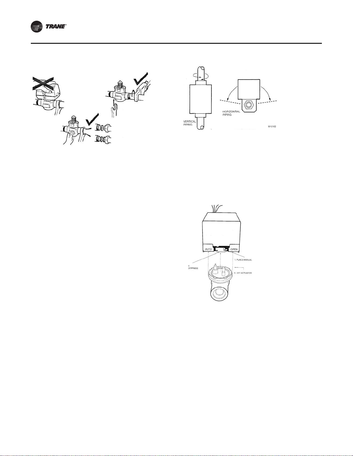
Isolation Valves
Installation
The valve can be mounted in any position on a vertical line.
If the valve is mounted horizontally, the actuator must be
even with or above the center line. Make sure there is
enough room to remove actuator cover for servicing.
Mount the valve on the tube or pipe.
Note: Make sure the flow through the valve is in the
direction indicated by the arrow stamped on the
valve body.
Servicing/Removal of Valves
The actuator can be removed from the valve body.
Removing the actuator is recommended of soldering is
being conducted near the valve.
To remove the actuator:
1. Place the manual operating lever in the Open position
(see Figure 21, p. 26).
2. Depress the locking button and lift actuator until it
separates from the valve body.
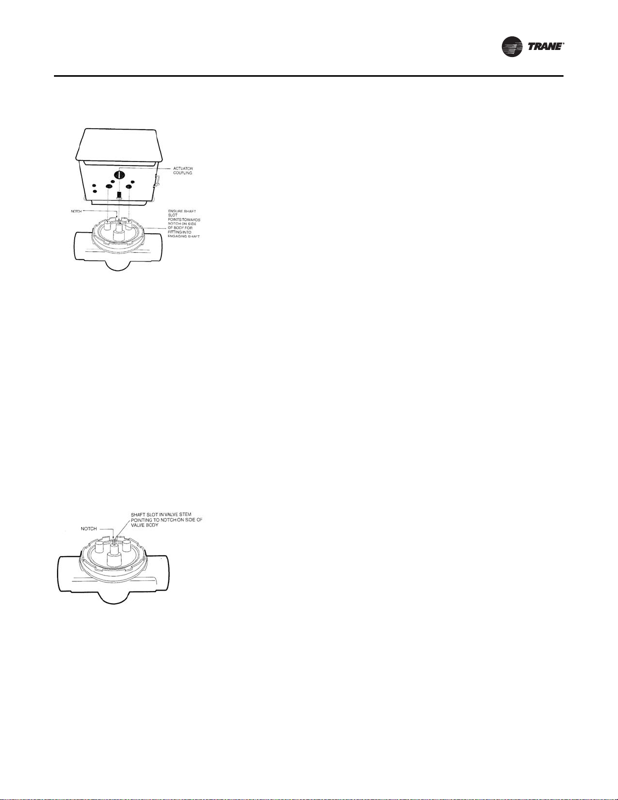
To install the actuator to the valve body:
1. Align the slot on the shaft of the valve with the valve
body notch on side of body (see Figure 22, p. 27).
Figure 19. Proper plumbing technique for modulating
valves
Figure 20. Proper mounting for isolation valves
Figure 21. Removing isolation valve actuator
Installation—Piping
UV-SVN02C-EN 27
2. Install body valve into pipe.
3. Wiring connections may be made either before or after
actua
tor installed on body.
4. Place the manual operating leve
r on the actuator in the
OPEN position.
5. Align actuator coupling to slot on the shaf
t of the valve
body and fit the head onto the valve body to ensure the
shaft seats correctly (see Figure 22).
6. Press the actuator and valve body until it secures
together
.
Soldering procedures are as follows:
1
. Remove actuator as stated earlier.
2. Place valves on the pipe. Rotate valve stem so the shaf
t
slot points at the notch in the side of the body (90O to
flow direction). This protects the plug inside the valve
by removing it from the seat (see Figure 23).
3. Sweat the joints, keeping outer surface free from
solder.
Note: Do not use silver solder due to high
temperature requirements.
Heating Coils with Direct
Expansion Cooling
Heating options for direct expansion cooling in the unit
ventilator are hot water, steam or electric heat.
These coils facilitate direct expansion cooling with
standard capacities. The supply and return connections
are located in the right hand end pocket. Hot water field
connections are made with a 5/8 in.\[15.9\] OD male
sweated joint, while steam coils have a 1 in.\[25.4\] male
pipe thread (MPT) connection (see Tab l e 10 , p . 2 3 ).
Electric heat coils provide a third way to supply heating to
the direct expansion cooling. The coil utilizes three to six
preheat elements which are factory-wired.
Figure 22. Installing isolation valve actuator
Figure 23. Preparation for soldering
28 UV-SVN02C-EN
Installation—Sensors
Control Options
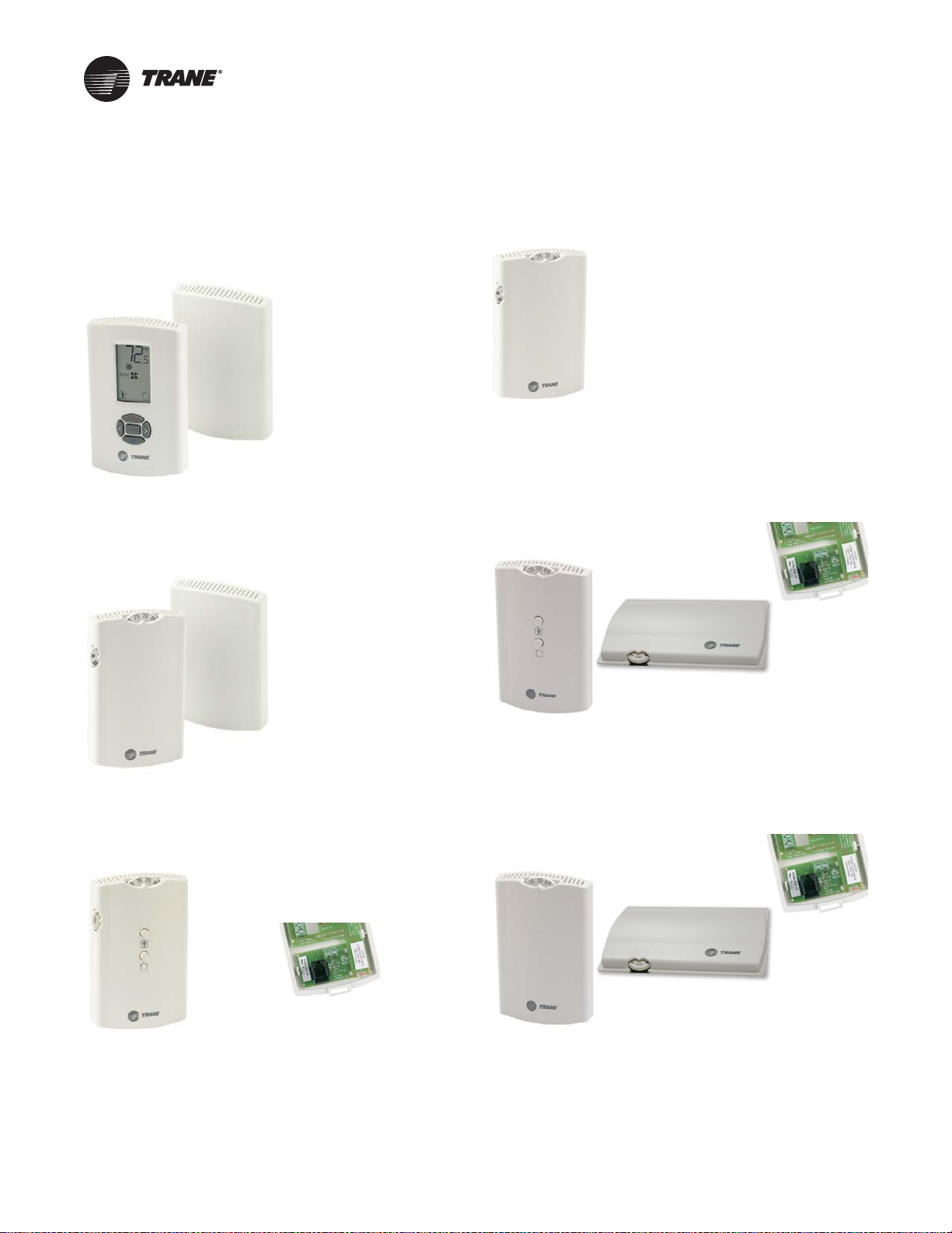
Figure 24. Wireless temp sensor with display
(SP, OALH, COMM)
Digit 19 = 3
Figure 25. Wireless temp sensor
(SP, OALMH, COMM)
Digit 19 = 4
Figure 26. Wall mtd temp sensor
(SP, OCC/UNOCC, OA, LMH, COMM)
Digit 19 = J
X13790822-04 (wall)
X13790855-01 (unit)
X13790492-01 (wall)
X13790855-01 (unit)
X13790842-01 (wall)
X13651467-02 (comm)
Figure 27. Unit mtd temp sensor
(SP, OALH, COMM)
Digit 19 = L
Figure 28. Split mtd zone sensor, unit mtd fan speed
switch, and wall mtd setpoint dial
with On/Cancel
Digit 19 = P
Figure 29. Split mtd zone sensor,
unit mtd fan speed switch, and
wall mtd setpoint dial
Digit 19 = Q
X13790843-01 (unit)
X13511527-01 (wall)
X13790849-01 (unit)
X13651467-02 (comm)
X13511529-01 (wall)
X13790849-01 (unit)
X13651467-02 (comm)
Installation—Sensors
UV-SVN02C-EN 29
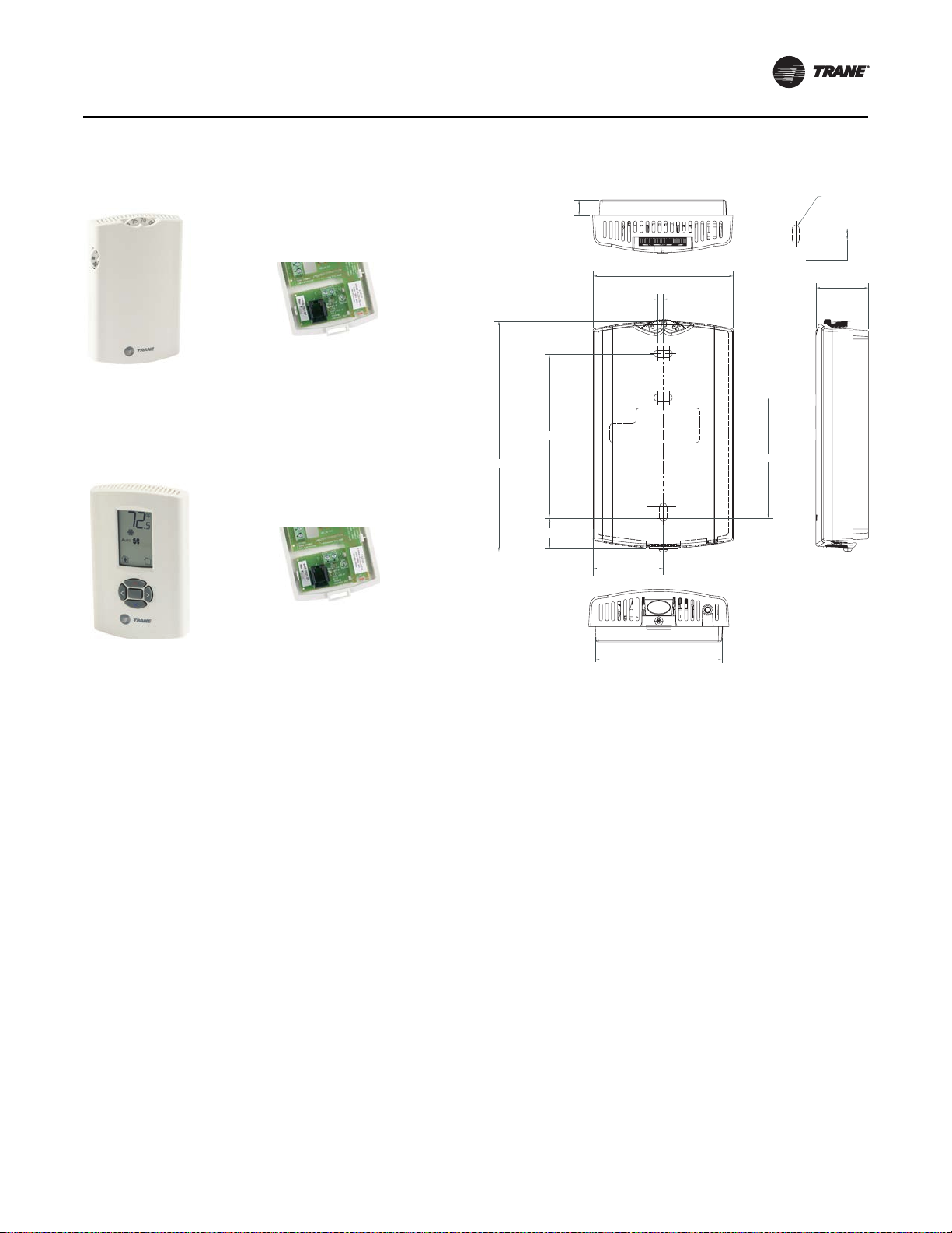
Installing Wall-Mounted Wired
Sensors
Reference the wall-mounted zone sensor dimensions in
Figure 32, p. 29. Position the sensor on an inside wall three
to five feet above the floor and at least 18 inches from the
nearest outside wall. Installing the sensor at a lower height
may give the advantage of monitoring the temperature
closer to the zone, but it also exposes the sensor to airflow
obstructions. Ensure that air flows freely over the sensor.
Sensor
When selecting a sensor location, avoid the following:
• Areas of direct sunlight
• Areas in the direct airstream of air diffusers
• Exterior walls and other walls that have a
temperature
differential between the two sides
• Areas that are close to heat sources
such as sunlight,
appliances, concealed pipes, chimneys, or other heat-
generating equipment
• Drafty areas
• Dead spots behind doors, projection screens, or
corner
s
• Walls that are subject to high vibration
• Areas with high humidity
• High traffic areas (to reduce acci
dental damage or
tampering)
Figure 30. Wall mtd temp sensor
(SP, OALMH, COMM)
Digit 19 = K
Figure 31. Wall mtd display temp sensor
(SP, OCC/UNOCC, OALMH, COMM)
Digit 19 = M
X13790841-01 (wall)
X13651467-02 (comm)
X13790886-04 (wall)
X13651467-02 (comm)
Figure 32. Wall-mounted wired and wireless zone
sensor dimensions
1. 0.31 in
2. TYP R.07 in (R1.9)
3. TYP 0.24 in)
4. 2.9 in
5. 1.08 in
6. 0.12 in
7. 3.39 in
8. 4.68 in
9. 2.48 in
10. 0.6 3 i n
11. 1.45 in
12. 2.62 in
1
2
3
4
5
6
7
8
9
0
-
=

Installation—Sensors
30 UV-SVN02C-EN
• Metal barriers between the receiver and the sensor (for
example, plastered walls with metal lathe or metal roof
decks)
• Thick, solid concrete walls between the receiver and
the sensor
• Placing the sensor inside metal enclosures
Height Requirements
It is recommended that you mount the back plate a
maximum distance of 54 inches above the floor. If a
parallel approach by a person in a wheelchair is required,
reduce the maximum height to 48 inches.
Note: Consult section 4.27.3 of the 2002 ADA (Americans
with Disability Act) guideline, and local building
codes, for further details regarding wheelchair
requirements.
Mounting Surfaces
Using the hardware provided, mount the back plate of the
sensor to a flat surface such as sheetrock or plaster, or an
electrical junction box. The sensor must be mounted
plumb for accurate temperature control and to ensure
proper air movement through the sensor.
• If mounting onto sheetrock or plaster
, use the plastic
threaded anchors (pre-drilling holes is not usually
necessary) and the two M3.5 x 20 mm mounting
screws.
• For mounting onto an electrical junction box, use the
two 6-32 x 3/4 in. screws.
Before beginning installation, consider the location
co
nsiderations below. Also, refer to the unit wiring
schematic for specific wiring details and point
connections.
Location Considerations
Avoid mounting the sensor in an area subject to the
following conditions:
• Dead spots, such as behind do
ors or in corners that do
not allow free air circulation.
• Air drafts from stairwells, outside doors, or
un
sectioned hollow walls.
• Radiant heat from the sun, fireplaces, appliances, etc.
• Airflow from adjacent z
ones or other units.
• Unheated or uncooled spaces behind the controller,
su
ch as outside walls or unoccupied spaces.
• Concealed pipes, air ducts, or chimneys in partition
sp
aces behind the controller.
Location Considerations for Wireless Zone
Sensors
Placement of the sensor is critical to proper operation (the
receiver is factory mounted on fan-coil units). For most
installations, barriers limit proper radio signal strength
more than distance. For best radio transmission range and
reliability, mount the receiver and sensor in line of sight.
Where this is not possible, try to minimize the number of
barriers between the pair of devices. In general, sheetrock
walls and ceiling tiles offer little restriction to the
transmission range for the sensor is as follows:
• Open range: 2,500 ft (packet error rate = 2%)
• Usable range: 200 ft
• Typical range: 75 ft
Fan Mode Switch Installation
The fan mode switch ships loose inside the unit accessory
bag. Follow the steps below to install the fan mode switch.
Items needed:
2 x 4 electrical junction box
1. Remove the brown wire if not using a field-supplied
damper.
2. Remove the terminals, cut and strip wires as required
fo
r installation.
3. Level and position a 2 x 4 electrical
junction box.
4. Follow the instructions given in “Wall-Mounted
Control Interconnection Wiring,” p. 41 and route the
wires as shown in the wiring diagram. R
efer to the
typical wiring diagram or to the unit specific diagram
on the unit.
5. Position the fan mode switch over the junction box
with the two screws supplied.
Zone Sensor Installation
Follow the procedure below to install the wired zone
sensor module.
1. Note the position of the setpoint adjustment knob and
gently pry the adjustment knob from the cover using
the blade of a small screwdriver.
2. Insert the screwdriver blade behi
nd the cover at the top
of the module and carefully pry the cover away from
the base.
3. To mount the sensor back plate:
a. Hold the back plate against the mounting surface
and ma
rk the screw locations.
b. Secure the back plate against the mounting surface
using included hardware.
4. To install the zone sensor module to a standard
ju
nction box:
a. Level and install a 2 x 4-in.
junction box (installer
supplied) vertically on the wall.
b. Pull the control wires through the cutout. Attach the
module to the wall using the screws provided.
5. Strip the insulation on the i
nterconnection wires back
0.25-inch and connect to TB1 (for wired sensors).
6. Screw down the terminal blocks (for wired sensors).
7. To replace the cover:
Loading...