


 Loading...
Installation
Operation
Maintenance
Tracer™ UC400
Programmable BACnet
Controller
For Factory Installation on Variable Air Volume (VAV) Units
|
|
May 2010 |
VAV-SVX07A-EN |
Warnings, Cautions and Notices
Warnings, Cautions and Notices. Note that warnings, cautions and notices appear at appropriate intervals throughout this manual. Warnings are provide to alert installing contractors to potential hazards that could result in personal injury or death. Cautions are designed to alert personnel to hazardous situations that could result in personal injury, while notices indicate a situation that may result in equipment or property-damage-only accidents.
Your personal safety and the proper operation of this machine depend upon the strict observance of these precautions.
Read this manual thoroughly before operating or servicing this unit.
ATTENTION: Warnings, Cautions and Notices appear at appropriate sections throughout this literature. Read these carefully.
WARNING: Indicates a potentially hazardous situation which, if not avoided, could result in death or serious injury.
CAUTION: Indicates a potentially hazardous situation which, if not avoided, could result in minor or moderate injury. It may also be used to alert against unsafe practices.
NOTICE: Indicates a situation that could result in equipment or property-damage only accidents.
WARNING
This equipment is to be serviced/installed by qualified personnel ONLY. Under NO circumstances should an unqualified person service/install it. Servicing/installing this equipment is a job requiring specific knowledge and MUST be left to a professional. It involves working with hazardous components that are potentially life threatening if not handled properly. Improperly installed, adjusted or altered equipment by an unqualified person could result in death or serious injury.
WARNING
Electrocution and Fire Hazards with Improperly Installed and Grounded Field Wiring!
Improperly installed and grounded field wiring poses FIRE & ELECTROCUTION hazards. To avoid these hazards, you MUST follow requirements for field wiring installation and grounding as described in NEC and your local/state electrical codes. All field wiring MUST be performed by qualified personnel. Failure to follow these requirements could result in death or serious injury.
Overview of Manual
Note: One copy of this document ships inside the control panel of each unit and is customer property. It must be retained by the unit's maintenance personnel.
This booklet describes proper installation, operation, and maintenance procedures for delivered air systems. By carefully reviewing the information within this manual and following the instructions, the risk of improper operation and/or component damage will be minimized. It is important that periodic maintenance be performed to help assure trouble free operation. Should equipment failure occur, contact a qualified service organization with qualified, experienced HVAC technicians to properly diagnose and repair this equipment.
© 2010 Trane All rights reserved |
VAV-SVX07A-EN |

Table of Contents |
|
General Information . . . . . . . . . . . . . . . . . . . . . . . . . . . . . . . . . . . . . . . . . . . . . . . . . . . |
. 5 |
Tracer UC400 BACnet Unit Controller . . . . . . . . . . . . . . . . . . . . . . . . . . . . . . . . |
. 5 |
Shipping & Storage . . . . . . . . . . . . . . . . . . . . . . . . . . . . . . . . . . . . . . . . . . . . . . . . |
6 |
Specifications . . . . . . . . . . . . . . . . . . . . . . . . . . . . . . . . . . . . . . . . . . . . . . . . . . . . . |
6 |
Tracer UC400 Controller Features . . . . . . . . . . . . . . . . . . . . . . . . . . . . . . . . . . . . |
8 |
VAV Start Up/Check Out Procedure . . . . . . . . . . . . . . . . . . . . . . . . . . . . . . . . . . . . . . |
12 |
Tracer UC400 Controller Pre-Power Check-Out . . . . . . . . . . . . . . . . . . . . . . . . |
12 |
Tracer UC400 Controller Power Wiring . . . . . . . . . . . . . . . . . . . . . . . . . . . . . . . |
13 |
LED Description and Behavior . . . . . . . . . . . . . . . . . . . . . . . . . . . . . . . . . . . . . . |
14 |
Communication Wiring . . . . . . . . . . . . . . . . . . . . . . . . . . . . . . . . . . . . . . . . . . . . |
15 |
Space Temperature Control Wiring . . . . . . . . . . . . . . . . . . . . . . . . . . . . . . . . . . |
17 |
Ventilation Flow control . . . . . . . . . . . . . . . . . . . . . . . . . . . . . . . . . . . . . . . . . . . |
21 |
Flow Tracking Control . . . . . . . . . . . . . . . . . . . . . . . . . . . . . . . . . . . . . . . . . . . . . |
21 |
Wireless Zone Sensor . . . . . . . . . . . . . . . . . . . . . . . . . . . . . . . . . . . . . . . . . . . . . |
22 |
Tracer™ UC400 Controller Operations . . . . . . . . . . . . . . . . . . . . . . . . . . . . . . . . . . . |
36 |
Connecting with the Tracer TU Service Tool . . . . . . . . . . . . . . . . . . . . . . . . . . |
36 |
Status Button . . . . . . . . . . . . . . . . . . . . . . . . . . . . . . . . . . . . . . . . . . . . . . . . . . . . . |
37 |
Data Log Button . . . . . . . . . . . . . . . . . . . . . . . . . . . . . . . . . . . . . . . . . . . . . . . . . . |
41 |
Controller Settings Button . . . . . . . . . . . . . . . . . . . . . . . . . . . . . . . . . . . . . . . . . |
45 |
Equipment Settings Button . . . . . . . . . . . . . . . . . . . . . . . . . . . . . . . . . . . . . . . . . |
48 |
Sequence of Operation . . . . . . . . . . . . . . . . . . . . . . . . . . . . . . . . . . . . . . . . . . . . . . . . . |
53 |
Calibration Sequence . . . . . . . . . . . . . . . . . . . . . . . . . . . . . . . . . . . . . . . . . . . . . . |
53 |
Occupancy Modes . . . . . . . . . . . . . . . . . . . . . . . . . . . . . . . . . . . . . . . . . . . . . . . . |
53 |
Space Temperature Control Single Duct/Fan-Powered Units . . . . . . . . . . . . |
55 |
Ventilation Flow Control . . . . . . . . . . . . . . . . . . . . . . . . . . . . . . . . . . . . . . . . . . . |
60 |
Flow Tracking . . . . . . . . . . . . . . . . . . . . . . . . . . . . . . . . . . . . . . . . . . . . . . . . . . . . |
62 |
Troubleshooting . . . . . . . . . . . . . . . . . . . . . . . . . . . . . . . . . . . . . . . . . . . . . . . . . . . . . . . |
64 |
Troubleshooting Procedures . . . . . . . . . . . . . . . . . . . . . . . . . . . . . . . . . . . . . . . |
64 |
Diagnostics . . . . . . . . . . . . . . . . . . . . . . . . . . . . . . . . . . . . . . . . . . . . . . . . . . . . . . |
64 |
LED Operation . . . . . . . . . . . . . . . . . . . . . . . . . . . . . . . . . . . . . . . . . . . . . . . . . . . . |
65 |
Tracer UC400 Controller Failure Troubleshooting Procedures . . . . . . . . . . . |
66 |
Tracer UC400 Controller Communication Loss Procedures . . . . . . . . . . . . . |
67 |
Wired Zone Sensor Failure Troubleshooting Procedures . . . . . . . . . . . . . . . |
68 |
Wired Zone Setpoint Failure Troubleshooting Procedures . . . . . . . . . . . . . . |
70 |
Wireless Zone Sensor Failure Troubleshooting Procedures . . . . . . . . . . . . . |
70 |
VAV-SVX07A-EN |
3 |

Airflow Failure Troubleshooting Procedures . . . . . . . . . . . . . . . . . . . . . . . . . . 75
Supply/Discharge Air Temp Sensor Failure Troubleshooting Procedures . 77
CO2 Sensor Failure Troubleshooting Procedures . . . . . . . . . . . . . . . . . . . . . . 78
VAV Damper Failure Troubleshooting Procedures . . . . . . . . . . . . . . . . . . . . . 79
VAV Series Fan Failure Troubleshooting Procedures . . . . . . . . . . . . . . . . . . 80
VAV Parallel Fan Failure Troubleshooting Procedures . . . . . . . . . . . . . . . . . 81
Trane/Honeywell Proportional Valve Check-Out Procedures . . . . . . . . . . . . 84
4 |
VAV-SVX07A-EN |

General Information
This chapter contains information about the following:
•Tracer™ UC400 BACnet Unit Controller
•Shipping & Storage
•Specifications
•Tracer UC400 Controller Enhancements
•Tracer UC400 Controller Features
Tracer UC400 BACnet Unit Controller
The Tracer UC400 controller is a programmable general purpose BACnet, microprocessor-based, Direct Digital Controller (DDC). When factory installed on Trane (Variable Air Volume) VAV terminal units, it is factory downloaded with appropriate VAV programs and configuration settings. Trane VAV units have been made with either pneumatic, analog electronic, or microprocessor controls (DDC VAV). This manual discusses only terminal units with BACnet Tracer UC400 controller DDC/ VAV controls. Factory installed DDC/VAV controls are available with all single duct terminal units, dual duct units, parallel fan-powered, and series fan-powered units. A single Tracer UC400 controller is needed for dual duct units, but programming is not provided from the factory.
The Tracer UC400 controller can be configured from the factory with three different application programs: Space Temperature Control (STC), Ventilation Flow Control (VFC), and Flow Tracking Control (FTC).
The Tracer UC400 controller programmed for STC modulates a VAV's damper blade based on a zone temperature, measured airflow, and setpoints to continuously control conditioned air delivery to the space. The volume of incoming air is monitored and the damper adjusts to provide accurate control independent of the duct pressure. The damper modulates between operator setpoints depending on space conditions. Additionally, fan and heat outputs may be energized depending on the application.
The Tracer UC400 controller configured for VFC can be applied to a VAV terminal and used to temper cold outdoor air (OA) that is brought into a building for ventilation purposes. The tempered air is intended to supply an air-handling unit (AHU), which provides comfort control to the zones it is serving. The VAV terminal supplies the correct amount of ventilation air, and when reheat is added, tempers the ventilation air to reduce the load on the air handler by sensing the discharge air temperature of the VAV unit and controlling its long-term average to the discharge air temperature setpoint.
The Tracer UC400 controller can be configured for FTC and has two VAV units with Tracer UC400 controllers working together to provide flow tracking control. One Tracer UC400 controller is configured from the factory with the Space temperature program and the other is downloaded with the FTC program. The STC airflow output is bound to the flow tracking controller airflow setpoint input. The flow tracking controller adds the configured airflow tracking offset (positive or negative) to the airflow setpoint (communicated airflow setpoint) and controls the airflow to this setpoint.
The Tracer UC400 controller is BTL compliant with BACnet, an open standard building automation protocol. It meets the Application Specific Controller (ASC) profile per ASHRAE 135-2004. This allows the Tracer UC400 controller to integrate with other BACnet systems.
Available Inputs
Inputs include a twisted/shielded communication link, zone sensor, duct temperature sensors (optional), Occupancy Sensor (optional), Discharge Air Temperature (DAT) and/or Supply Air Temperature (SAT), CO2 sensor, and 24 VAC power. In addition to the points used for the VAV application, the spare inputs and outputs on the Tracer UC400 controller may be used for ancillary control, which can be programmed using Tracer TU Tracer Graphical Programming 2 (TGP2).
Note: For more information on using spare points, see BAS-SVX20*-EN Tracer UC400
Programmable Controller Installation, Operation, and Maintenance.
VAV-SVX07A-EN |
5 |

General Information
Shipping & Storage
Each VAV order ships with service literature. When unpacking, make sure that the literature is not lost or discarded with the packing material. Visually inspect the individual components for obvious defects or damage. All components are thoroughly inspected before leaving the factory. Any claims for damage incurred during shipment must be filed with the carrier.
If any component of the VAV system and/or field installed accessories must be stored for a period of time prior to installation, they must be protected from the elements. The storage location temperature should be between -40° to 150°F (-40° to 65.6°C) and the relative humidity should be 10% to 90%, non-condensing. The warranty will not cover damage to the VAV or controls due to negligence during storage. A controlled indoor environment must be used for storage.
Specifications
AC wiring specifications
Wire
16 AWG (maximum) copper wire
Transformer
•UL Listed, Class 2 power transformer 19-30 VAC (24 VAC nominal)
•The transformer must be sized to provide adequate power to the Tracer UC400 controller (24 VA) and outputs (maximum 12 VA for each binary output)
Storage
•Temperature: -48°F to 203°F (-44°C to 95°C)
•Relative humidity: Between 5% to 95% (noncondensing)
Operating
•Temperature: -40°F to 158°F (-40°C to 70°C)
•Humidity: Between 5% to 95% (noncondensing)
•Power: 19-30 VAC (24 VAC nominal) 50-60 Hz 24 VA
•Mounting weight (controller): Mounting surface must support .80 lb. (364 kg)
•Environmental rating (enclosure): NEMA 1
•Altitude: 6,500 ft. maximum (1,981 m)
•Installation: Category 3
•Pollution Degree 2
Analog inputs AI1 to AI5
•AI1: Space temperature; thermistor: 10 kΩ@ 77°F (25°C) Range: 32°F to 122°F (0°C to 50°C)
•AI2: Space setpoint; potentiometer: 1 kΩ
From 50 to 90°F (10 to 32.2°C), */** (thumbwheel) functionality supported
•AI3: Spare
•AI4: Discharge air temperature: 10 kΩ@ 77°F (25°C) From -40 to 212°F (-40 to 100°C)
•AI5: Supply air temperature: 10 kΩ@ 77°F (25°C) From -40°F to 212°F (-40 to 100°C)
6 |
VAV-SVX07A-EN |

General Information
Universal Inputs UI1 and UI2
•UI1: Spare, but recommended for Relative Humidity. Resistive/thermistor inputs, 0-10VDC inputs, or 4-20 mA inputs. Current Mode Impedance: 200 ohm. Voltage Mode Impedance: 10 kohm min.
•UI2: Spare, but recommended for CO2. Resistive/thermistor inputs, 0-10VDC inputs, or 4-20 mA inputs. Current Mode Impedance: 200 ohm. Voltage Mode Impedance: 10 kohm min.
Pressure Inputs P1 and P2
•P1: Supply air flow; pressure transducer: From 0 to 2 in. water column (0 to 498 Pa)
•P2: Spare, but recommended for dual duct secondary air flow
Binary input BI1 to BI3
•BI1: Occupancy
•BI2: Spare
•BI3: Spare
Binary outputs BO1 to BO9
Table 1. Binary outputs
Binary Outputs |
Type |
Output Rating |
Pilot duty |
|
|
|
|
BO1 |
Fan |
10A up to 277 VAC |
10A at 30 VAC/VDC, 2A at 120 VAC, 8A at 250 VAC, |
|
|
|
|
BO2 |
Spare Relay |
10A up to 277 VAC |
10A at 30 VAC/VDC, 2A at 120 VAC, 8A at 250 VAC, |
|
|
|
|
BO3 |
Spare Relay |
10A up to 277 VAC |
10A at 30 VAC/VDC, 2A at 120 VAC, 8A at 250 VAC, |
|
|
|
|
BO4 |
Spare Relay |
10A up to 277 VAC |
10A at 30 VAC/VDC, 2A at 120 VAC, 8A at 250 VAC, |
|
|
|
|
BO5 |
Heat stage 3 TRIAC |
24-27 VAC, .5A Resistive VA |
|
|
|
|
|
BO6 |
Heat stage 2/Water Valve Close TRIAC |
24-27 VAC, .5A Resistive VA |
|
|
|
|
|
BO7 |
Heat stage 1/Water Valve Open TRIAC |
24-27 VAC, .5A Resistive VA |
|
|
|
|
|
BO8 |
Air Damper Close TRIAC |
24-27 VAC, .5A Resistive VA |
|
|
|
|
|
BO9 |
Air Damper Open TRIAC |
24-27 VAC, .5A Resistive VA |
|
|
|
|
|
Analog outputs AO1 and AO2
•AO1: Spare. Voltage output is 0 to 10 VDC, 500 ohm min. impedance. Current output is 4 - 20 mA, 500 ohm max. impedance
Note: ECM fan for future production.
•AO2: Spare. Voltage output is 0 to 10 VDC, 500 ohm min. impedance. Current output is 4 - 20 mA, 500 ohm max. impedance
Note: For more information about wiring spare I/O, see the Tracer™ UC400 controller Installation Sheet X39641064*-01.
Agency listings/compliance
UL - Open Energy Management Equipment, 834Y
UL94-5V Flammability
CE marked
FCC Part 15, Subpart B, Class B Limit
AS/NZS CISPR 22:2006
VCCI V-3/2008.04
VAV-SVX07A-EN |
7 |

General Information
ICES-003, Issue 4:2004
Table 2. Agency listings/compliance
Standard |
Test Level |
|
|
|
|
EN 61326-1: 2006 Electrical equipment for measurement, control and |
|
|
laboratory use - EMC requirements, part 1: General Requirements. |
|
|
|
|
|
EN 55022: 2006 (CISPR 22: 2005 + A1: 2005) Radiated Emissions |
Class B Limit (30 MHz - 1000 MHz, 1 GHz - 2 GHz) |
|
|
|
|
EN 55022: 2006 (CISPR 22: 2005 + A1: 2005) Conducted Emissions |
150 kHz - 30 MHz |
|
|
|
|
EN 61000-4-2: 1995 + A1: 1998 + A2: 2001 Electrostatic Discharge |
8 kV air, 4 kV contact |
|
(ESD) |
||
|
||
|
|
|
EN 61000-4-3: 2002 Radiated Fields |
10 V/m, 80 MHz - 1000 MHz 3 V/m, 1.4 GHz - 2.0 GHz 1 V/m, 2.0 GHz |
|
- 2.7 GHz |
||
|
||
|
|
|
EN 61000-4-4: 2004 Fast Transients |
I/O port, 1 Kv AC inputs & output ports, 2 kV |
|
|
|
|
EN61000-4-5: 1995 + A1: 2001 Surge Transients |
AC input ports (L? L), differential mode, 1 kV |
|
|
|
|
EN61000-4-6: 1996 + A1: 2001 Conducted Disturbance |
3 V, 0.15 MHz - 80 MHz |
|
|
|
|
EN61000-4-8: 1993 + A1: 2001 Power Frequency Magnetic Field |
30 A/m, 50 Hz |
|
|
|
|
EN61000-4-11 Second Edition: 2004 Voltage Dips and Interruptions |
0% Vnom, 1 cycle; 70% Vnom, 25 cycle; 40% Vnom, 10 cycle, 0% |
|
Vnom, 250 cycle |
||
|
||
|
|
Note: Trane declares that the product listed is in conformity with the essential requirements of Council Directive 2004/108/EC (electromagnetic compatibility) and conforms to the standards in this table.
Mounting
The Tracer™ UC400 controller is factory installed in the VAV control box.
Setting up the Tracer UC400 Controller on a BACnet Link
Tracer SC and BACnet Communications Link Wiring
Use 18 AWG shielded communication wire for BACnet MS/TP installations. Limit BACnet MS/TP wiring links to 4,000 ft. There is a 60 device maximum per link (without a repeater). Two BACnet links are available on the SC. Connect the BACnet link to the Tracer UC400 controller terminals labeled Link. Incoming wires can be connected to the first two terminals, and the outgoing wires can be connected to the second set of terminals, such that there is only one wire per termination. Refer to Chapters 2 and 3 for further information about wire selection. See also wiring guide BAS- SVN03*-EN (Unit Controller Wiring for Tracer SC™System Controller) for required wire type, topology, and active termination resistors for BACnet links.
Rotary Switches
There are three rotary switches on the front of the Tracer UC400 controller (see Figure 3, p. 16). Use these switches to define a three-digit address when it is installed in a BACnet system (for example, 107, 120, and so on), whether with other Trane BACnet controls or controls from another vendor. This three-digit rotary switch setting is used as both the BACnet MAC address and the BACnet Device ID.
Note: Valid addresses are 001 to 120.
Important: Each Tracer UC400 controller on the BACnet link must have a unique rotary switch setting, otherwise communication problems will occur.
Tracer UC400 Controller Features
Controller Interface Flexibility
The Tracer UC400 controller allows VAV units to communicate on a BACnet MS/TP link. This controller works in standalone mode, peer-to-peer with one or more other units, or when connected to a Tracer SC or a 3rd party building automation system that supports BACnet.
8 |
VAV-SVX07A-EN |

General Information
Flow Tracking
The Tracer™ UC400 controller is designed with the ability to be applied in flow tracking applications. This allows the controller to be paired with one of its peers to mirror the flow of the lead unit, with or without an offset (positive or negative static pressure as desired).
Ventilation Flow Control with Tempering
The Tracer UC400 controller is designed with the ability to be applied in ventilation flow control applications. These applications pair a fresh air unit with ventilation boxes to provide fresh (tempered) air to a zone. This feature also includes a freeze protection sequence to protect the hot water reheat coil from low supply air temperatures.
Auto-commissioning Sequence
The TracerUC400 controller is designed with an auto-commissioning sequence. With a discharge air temperature sensor, this feature exercises the air valve, fan, and heat in the box and records the temperature before and after the action. This allows the installer to more easily verify the operation of the unit and commission by exception. An auto-commissioning report can be generated with Tracer TU service tool.
Automatic Calibration
The Tracer UC400 controller is designed to automatically calibrate the flow transducer each time the unit transitions to unoccupied. This eliminates the need to initiate/schedule calibration for most installations. The exception is 24/7 sites, in which case Tracer SC can be used to initiate/schedule calibration.
Temporary Heat (Construction Mode)
Upon reset (and power-up) if the controller does not detect a valid space temperature the controller will provide temporary heat by driving the air valve to the heating maximum position.
Note: Note that the unit will only provide heat if hot air is being provided by the air-handling unit.
Local Versus Remote Reheat Flexibility
The controller can be configured to have local and/or remote heat. Plus, configuration flexibility is offered that allows the installer to select whether local or remote heat has priority.
Spare Inputs and Outputs
The Tracer UC400 controller has spare I/O that are not used by the VAV applications. These spare I/O can be programmed using the Tracer Graphical Programming editor (by means of the Tracer TU service tool) to measure and/or control ancillary devices such exhaust fans, second air valve for dual duct VAV or sensing relative humidity.
Removable Terminals
The Tracer UC400 controller connectors are two-part connectors that have 5.08 mm pin separation. The headers are attached on the Tracer UC400 controller itself. The other portion of the connector is either a screw terminal (for field wiring) or a terminal housing (for factory wiring). Spare screw terminals come factory installed for field mounted wired zone sensors and common accessories.
Wireless Zone Sensors
The Tracer UC400 controller is compatible with the latest wireless zone sensors available from Trane. Wireless zone sensors provide flexibility of sensor location and re-location as well as reducing the cost of installation. Wireless zone sensor receivers are available as a factory installed option.
VAV-SVX07A-EN |
9 |

General Information
Flash Download
The Tracer™ UC400 controller has been designed with flash memory. This allows the option of upgrading the controller in the field (features, corrections to defects) without changing out the controller.
Trane Controller Compatibility
The Tracer UC400 controller is a BACnet-compliant controller. As such, the controller is compatible with the latest generation of Trane controls. This allows the Tracer UC400 controller to exist on the same communication wire as the rest of our controllers and share data with them as required.
Drive Min and Max from Zone Sensor
When applied with a Trane zone sensor module that includes a thumbwheel setpoint or a LCD display, the Tracer UC400 controller can easily be overridden to minimum and maximum flow. By simply turning the thumbwheel to "*" or increasing the setpoint to maximum on display sensors (end of range in one direction) the controller drives the air valve to the minimum cooling flow setpoint. Similarly, turning the thumbwheel to the "**" or decreasing the setpoint to minimum on display sensors (end of range in the other direction) the controller drives the air valve to the maximum cooling flow setpoint.
Auto-commissioning Report (Tracer SC, Tracer TU)
Tracer SC and Tracer TU both include auto-commissioning reports that extracts and formats the commissioning data for each VAV controller. This commissioning report is valuable both for the installer and for the owner. The feature enables the system to be commissioned by exception -- a benefit for the installer. The feature also can be used as validation -- valuable to the owner.
Simpler VAS
Tracer SC includes a new VAV Air System (VAS) specifically designed for both BACnet and LonTalk VAV controllers. This new VAS was designed to be much simpler to understand and provides a wizard to aid in first time setup of a VAS.
Static Pressure Optimization
As a part of the standard application, VAS calculates the duct static pressure setpoint based on the VAV unit with a damper in the maximum flow position.
Ventilation Optimization
As a part of the standard application, the VAV system has the ability to calculate the ventilation setpoint for the air-handling unit. In addition, the Tracer UC400 controllers have a ventilation ratio limit feature that automatically increases airflow to maintain the required ventilation while operating within system limits for outside air percent concentrations in the supply air stream.
CO2-Based Demand Control Ventilation
As a part of the standard application, the VAV system has the ability to calculate the ventilation setpoint for the air-handling unit based on the CO2 concentration in one or more spaces.
Ventilation Flexibility
Ventilation can be managed in the following ways:
•Fixed occupancy ventilation setpoint
•Scheduled (or otherwise calculated) ventilation setpoint
•Occupancy sensor to switch between normal and reduced ventilation
•CO2 sensor for demand-controlled ventilation
10 |
VAV-SVX07A-EN |
General Information
Temperature Statistics
As a part of the standard application, both the VAS and Area applications calculate the minimum space temperature (and source), maximum space temperature (and source), and the average space temperature.
Tracer™ UC400 Controller Compatibility
The Tracer UC400 controller integrates with other BACnet systems and devices using BACnet MS/ TP. The Tracer UC400 controller provides standard BACnet objects (data points) that can be read by and/or written to by other systems.
Note: See BACnet Integration Guide (BAS-SVP01*-EN) for more information on the Tracer UC400 controller interface to non-Trane systems.
Note: BACnet is the Building Automation and Control Network (BACnet and ANSI/ASHRAE Standard 135-2004) protocol.
Table 3. Tracer UC400, Tracer VV550, and VAV 4.2 controller comparisons
Tracer UC400 VAV |
Tracer VV550/VV551 |
VAV 4.2 |
|
|
|
|
|
Supports BACnet. |
Supports LonTalk (Comm5). |
Supports only Comm4 or Comm3 (VariTrac or |
|
VariTrane). |
|||
|
|
||
|
|
|
|
Local CO2 sensor input is available. |
No local CO2 sensor input. Uses only a |
Local CO2 sensor input is available. |
|
communicated value. |
|||
|
|
||
|
|
|
|
Single star (*) initiates cool minimum |
Single star (*) initiates cool minimum |
Single star (*) initiates maximum flow override |
|
after pressing the ON button. Override is held |
|||
airflow override.(a) |
airflow override.(a) |
||
until you move the thumbwheel. |
|||
|
|
||
|
|
|
|
Double star (**) initiates cool maximum |
Double star (**) initiates cool maximum |
Double star (**) initiates unoccupied override |
|
after pressing the ON button. Override is held |
|||
airflow override.(b) |
airflow override.(b) |
||
until you move the thumbwheel. |
|||
|
|
||
|
|
|
|
Does not support VariTrac central control |
Does not support VariTrac central control |
Does support VariTrac CCP2 and CCP3. |
|
panel (CCP2 and CCP3). |
panel (CCP2 and CCP3). |
||
|
|||
|
|
|
|
Supports ventilation flow control. |
Supports ventilation flow control. |
Does not support ventilation flow control. |
|
|
|
|
|
Supports flow tracking control. |
Supports flow tracking control. |
Does not support flow tracking control. |
|
|
|
|
|
Supports enhanced ventilation control |
Supports enhanced ventilation control |
Does not support enhanced ventilation control |
|
sequences. |
sequences. |
sequences. |
|
|
|
|
|
Supports auto-commissioning sequence. |
Supports auto-commissioning sequence. |
Does not support auto-commissioning |
|
sequence. |
|||
|
|
||
|
|
|
|
Does not support zone sensor air balance |
Supports zone sensor air balance |
Does not support zone sensor air balance |
|
sequence. |
sequence. |
sequence. |
|
|
|
|
(a)By simply turning the thumbwheel to "*" or increasing the setpoint to maximum on display sensors (end of range in one direction) the controller drives the air valve to the minimum cooling flow setpoint.
(b)Turning the thumbwheel to the "**" or decreasing the setpoint to minimum on display sensors (end of range in the other direction) the controller drives the air valve to the maximum cooling flow setpoint.
VAV-SVX07A-EN |
11 |

VAV Start Up/Check Out Procedure
This chapter contains information about the following:
•Tracer™ UC400 Controller Pre-Power Check-Out
•Tracer UC400 Controller Power Wiring
•Communication Wiring
•Space Temperature Control Wiring
•Zone Sensor Wiring
•Duct Temperature Sensor Wiring
•Binary Input Wiring
•Binary Output Wiring
•Zone Sensor Check-Out
•Ventilation Flow Control
•Flow Tracking Control
•Wireless Zone Sensor
Tracer UC400 Controller Pre-Power Check-Out
WARNING
Live Electrical Components!
During installation, testing, servicing and troubleshooting of this product, it may be necessary to work with live electrical components. Have a qualified licensed electrician or other individual who has been properly trained in handling live electrical components perform these tasks.
Failure to follow all electrical safety precautions when exposed to live electrical components could result in death or serious injury.
•Check the supply voltage at XFRM. Proper polarity must be maintained. The 24 VAC is the hot side (+) and is the ground side (-) of the 24 VAC input. Refer to Figure 4, p. 18 for the Tracer UC400 controller terminal locations. The Tracer UC400 controller cannot be powered from a common 24 VAC transformer that is supplying power to a device containing a full-wave rectifier bridge in its power supply. The acceptable voltage is 19 to 30 VAC (24 VAC nominal). However, voltages at either extreme may result in increased system instability.
•Verify communications wiring has properly been terminated to link plus and negative at XFRM 24 VAC (+) and (-) terminals. Polarity must be maintained on the BACnet communications link.
•Verify that the zone sensor connections are correct as detailed in the Tracer UC400 controller wiring section.
•If heat has been added to the unit, verify that the proper output connections have been made as detailed in the Tracer UC400 controller wiring section.
•Verify that the tubing is properly connected to the differential pressure transducer.
12 |
VAV-SVX07A-EN |

VAV Start Up/Check Out Procedure
Tracer UC400 Controller Power Wiring
Power Requirements
WARNING
Hazardous Voltage!
Disconnect all electric power, including remote disconnects before servicing. Follow proper lockout/tagout procedures to ensure the power can not be inadvertently energized. Failure to disconnect power before servicing could result in death or serious injury.
WARNING
Electrocution and Fire Hazards with Improperly Installed and Grounded Field Wiring!
Improperly installed and grounded field wiring poses FIRE & ELECTROCUTION hazards. To avoid these hazards, you MUST follow requirements for field wiring installation and grounding as described in the National Electrical Codes (NEC) and your local/state electrical codes. All field wiring MUST be performed by qualified personnel. Failure to follow these requirements could result in death or serious injury.
NOTICE
Use Copper Conductors Only!
Unit terminals are not designed to accept other types of conductors. Failure to use copper conductors could result in equipment damage.
Use at a minimum 16 AWG for power wiring and connect to terminal XFRM 24 VAC and . The 24 VAC is required to power the Tracer UC400 controller and has an acceptable voltage tolerance of 19 to 30 VAC. Refer to Figure 4, p. 18 and Figure 5, p. 19 for the Tracer UC400 controller terminal locations. Replace the control box cover after field wiring to prevent any electromagnetic interference.
Note: A dedicated 24 VAC, 75VA NEC class 2 transformer is recommended to power the Tracer UC400 controller. When powering multiple controllers from one transformer, polarity must be maintained. Terminal 24 VAC is designated positive (+) and terminal is negative (-) to the unit casing ground.
The power consumption for cooling only Series F Models (VariTrac and VariTrane) is 28 VA. To determine the total Tracer UC400 controller power requirement, add the power consumption per stage to the circuit board power requirement. For example, a Series F unit containing magnetic contactors with three stages of reheat would consume 54 VA.
Table 4. VA for factory installed component
Style |
Volt Amps |
|
|
F - Style Actuator: |
4 VA |
|
|
Air Valve Actuator C through E Style: |
12 VA |
|
|
Fan Power Fan Output: |
6 VA |
|
|
Hot Water Proportional: |
4 VA |
|
|
Hot Water 2 Position: |
6.5 VA |
|
|
Electric Heater Magnetic Contactor: |
10 VA |
|
|
Electric Heater Mercury Contactor: |
12 VA |
Note: VariTrane cooling only Series D and E models consume 20 VA (12 VA for the actuator and 8 VA for the board). The heating output ratings remain the same. Refer to Figure 4, p. 18 and Figure 5, p. 19 for the Tracer UC400 controller terminal locations and for wiring of output devices.
VAV-SVX07A-EN |
13 |
VAV Start Up/Check Out Procedure
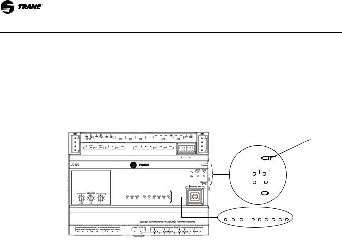
LED Description and Behavior
There are 15 LEDs on the front of the Tracer UC400 controller. Figure 1, p. 14 shows the locations of each LED and describes the behavior of each.
Tracer UC400 Controller Module
Figure 1. LED locations
Marquee LED
LINK IMC
TX
RX
SERVICE
BO1 BO2 BO3 BO4 BO5 BO6 BO7 BO8 BO9
LED Description and Operation
There are 15 LEDs on the front of the Tracer UC400 controller. Figure 1, p. 14 shows the locations of each LED and a description of its behavior in specific instances.
Marquee LED
•Shows solid green when the Tracer UC400 controller is powered and operating normally.
•Shows solid red when the Tracer UC400 controller is powered, but represents low power or a malfunction.
•Blinks red when an alarm exists.
LINK
•The TX LED blinks green at the data transfer rate when the Tracer UC400 controller transfers data to other devices on the link.
•The RX LED blinks yellow at the data transfer rate when the Tracer UC400 controller receives data from other devices on the link.
IMC
•The TX LED blinks green at the data transfer rate when the Tracer UC400 controller transfer data to other devices on the IMC bus.
•The RX LED blinks yellow at the data transfer rate when the Tracer UC400 controller receives data from other devices on the IMC bus.
Service
Shows solid green when pressed.
BO1 to BO9
Shows solid green when corresponding binary output is on.
14 |
VAV-SVX07A-EN |
VAV Start Up/Check Out Procedure
Communication Wiring
WARNING
Electrocution and Fire Hazards with Improperly Installed and Grounded Field Wiring!
Improperly installed and grounded field wiring poses FIRE & ELECTROCUTION hazards. To avoid these hazards, you MUST follow requirements for field wiring installation and grounding as described in NEC and your local/state electrical codes. All field wiring MUST be performed by qualified personnel. Failure to follow these requirements could result in death or serious injury.
Communication Link Wiring Requirements
•Use 18 AWG Trane purple-shielded communication wire for BACnet installations.
•Link limit of 4,000 ft and 60 devices maximum (without a repeater).
•Use a Trane BACnet termination on each end of the link.
•Use daisy chain topology. See Figure 2, p. 15.
•Maintain polarity.
Recommended Wiring Practices
To ensure proper network communication, follow these recommended wiring and planning guidelines when installing communication wire:
•All wiring must comply with the National Electrical Code (NEC) and local codes.
•Make sure that 24 VAC power supplies are consistent in how they are grounded. Avoid sharing 24 VAC between controllers.
•Avoid over tightening cable ties and other forms of cable wraps. This can damage the wires inside the cable.
•Do not run communication cable alongside or in the same conduit as 24 VAC power. This includes the conductors running from TRIAC-type inputs.
•In open plenums, avoid running wire near lighting ballasts, especially those using 277 VAC.
•Use same communication wire type, without terminators, for the zone sensor communication stubs from the Tracer UC400 controller IMC terminals to the zone sensor communication module.
Note: For more information see wiring guide BAS-SVN03*-EN, Unit Controller Wiring for Tracer SC™ System Controller.
Figure 2. BACnet link wiring in daisy chain configuration with Trane BACnet terminators and zone senor communication stubs
+ |
BACnet Terminator
|
|
|
+ |
IM |
BI |
LINK |
IMC |
VDC |
|
AI |
AI |
AI |
AI |
AI |
P P
LINK IM
TX
RX
SERVI
|
|
|
+ |
IM |
BI |
LINK |
IMC |
VDC |
|
AI |
AI |
AI |
AI |
AI |
P P
LINK IM
TX
RX
SERVI
|
|
|
+ |
IM |
BI |
LINK |
IMC |
VDC |
|
AI |
AI |
AI |
AI |
AI |
|
|
|
|
|
|
P |
P |
+ |
|
|
|
|
|
||
|
|
|
|
|
LINK |
IM |
|
|
|
|
|
TX |
|
|
|
|
|
|
RX |
|
|
|
|
|
|
SERVI |
|
BACnet Terminator
VAV-SVX07A-EN |
15 |
VAV Start Up/Check Out Procedure
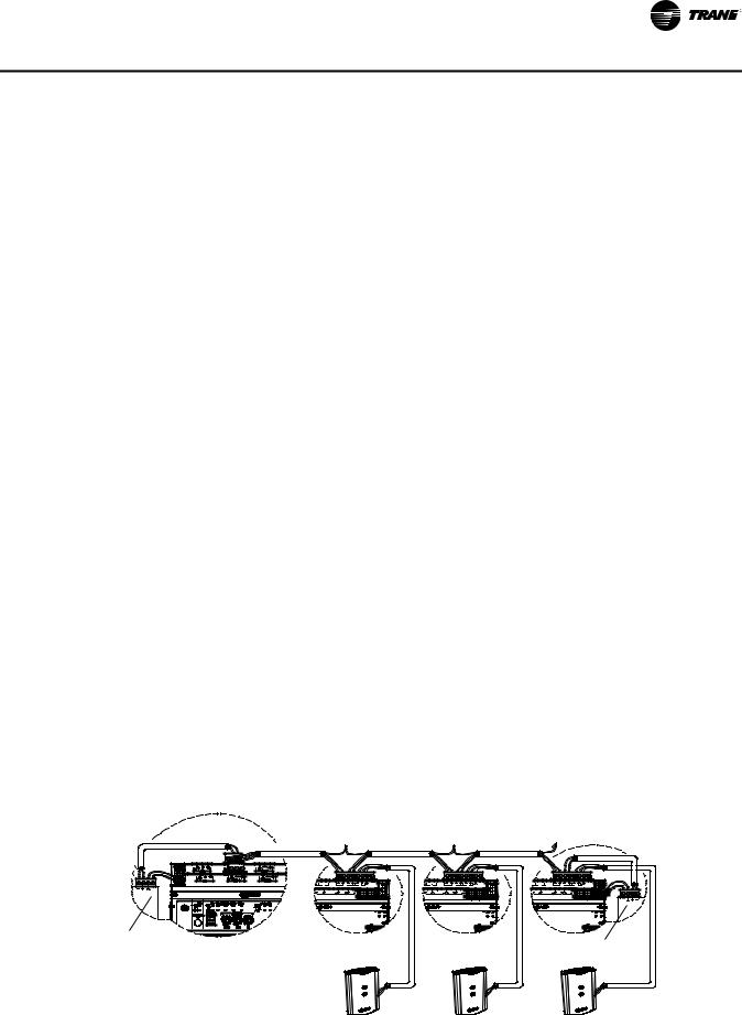
Rotary Switches
There are three rotary switches on the font of the Tracer™ UC400 controller device that are used to define a three-digit address when the Tracer TU service tool is installed on a BACnet communications network. The three-digit address setting is used as both the BACnet MAC address and the BACnet device ID.
Note: Valid MAC addresses are 001 to 120 for BACnet.
Figure 3. Setting rotary switches
9 |
0 |
1 |
8 |
|
2 |
|
|
|
7 |
|
3 |
|
|
|
6 |
5 |
4 |
|
||
|
|
x100
ADDRESS
|
9 |
0 |
1 |
8 |
|
||
|
|
2 |
|
|
|
|
|
7 |
|
3 |
|
|
|
||
|
6 |
5 |
4 |
|
|
||
|
x10 |
||
9 |
0 |
1 |
8 |
|
2 |
|
|
|
7 |
|
3 |
|
|
|
6 |
5 |
4 |
|
||
|
|
x1
Example of before and after setting addresses
Important: Each Tracer UC400 controller device on the BACnet link must have a unique rotary switch setting, otherwise, communication problems will occur.
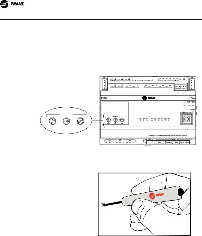
Use a 1/8 inch flathead screwdriver to set rotary switches.
9 |
0 |
1 |
|
|
2 |
||||
8 |
|
|
3 |
|
7 |
|
|
||
6 |
4 |
|||
|
||||
|
5 |
|
|
|
16 |
VAV-SVX07A-EN |

VAV Start Up/Check Out Procedure
Space Temperature Control Wiring
Zone Sensor Hardwired Option
Depending on the zone sensor options used, a maximum of seven wires may be required to run from the Tracer™ UC400 controller to the zone sensor. The zone sensor options are:
•Zone sensor (temperature only) - Part Number X1351152801.
•Zone sensor with timed override (TOV) on/cancel button - Part Number X1351153001.
•Zone sensor with adjustable setpoint thumbwheel - Part Number X1351152901.
•Zone sensor with adjustable setpoint thumbwheel, timed override (TOV) on/cancel button - Part Number X1351152701.
•Zone sensor with digital display - Part Number X1379088601. (Display sensor has factory mounted communication module.)
•Communications module - Part Number X1365146702. (for one box of 12)
Zone Sensor Wireless Option
Wireless zone sensors are available individually or on sensor/receiver sets. A receiver is used to receive the signal from the wireless zone sensor and can be factory installed. See BAS-SVX04*-EN for additional details on setup of the wireless zone sensors.
Note: Currently, wireless sensors do not provide a communication module option. It is recommended that at least one wired sensor with communications module be installed within the network of controllers, for service tool connection.
•Wireless zone sensor (temperature only)
–Sensor/Receiver Set - Part Number X1379082301.
–Sensor only - Part Number X13790821.
•Wireless zone sensor with adjustable setpoint thumbwheel (°F), timed override (TOV) on/cancel button
–Sensor/Receiver Set - Part Number X13790496.
–Sensor only - Part Number X13790492.
•Wireless zone sensor with adjustable setpoint thumbwheel (°C), timed override (TOV) on/cancel button
–Sensor/Receiver Set - Part Number X13790498.
–Sensor only - Part Number X13790494.
•Wireless zone sensor with digital display
–Sensor/Receiver Set - Part Number X1379082401.
–Sensor only - Part Number X1379082201.
•Wireless receiver only - Part Number X13790854.
VAV-SVX07A-EN |
17 |

VAV Start Up/Check Out Procedure
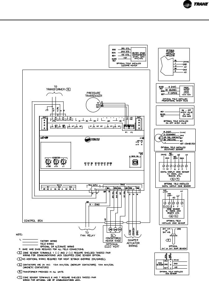
Figure 4. Tracer UC400 controller wiring connection diagram: single duct unit
18 |
VAV-SVX07A-EN |
VAV Start Up/Check Out Procedure
Figure 5. Tracer UC400 controller wiring connection diagram: fan powered unit
VAV-SVX07A-EN |
19 |

VAV Start Up/Check Out Procedure
Zone Sensor Wiring
Location and Mounting
A zone sensor in each control zone should be located in the most critical area of the zone. Sensors should not be mounted in direct sunlight or in the area's supply air stream. Subdivision of the zone may be necessary for adequate control and comfort. Avoid mounting zone sensors in areas subject to the following:
•Drafts or "dead spots" behind doors or corners.
•Hot or cold air ducts.
•Radiant heat from the sun or appliances.
•Concealed pipes or chimneys.
•Unheated or uncooled surfaces behind the sensor such as outside walls.
•Air flows from adjacent zones or other units.
Wiring
Each unit must be controlled by a zone sensor that utilizes a standard 10K ohm at 77°F thermister for temperature outputs. Field wiring for the zone sensors must meet the following requirements:
•18 to 22 AWG stranded, tinned-copper, shielded, twisted-pair wire is recommended.
•Maximum wire length 300 ft. (100 m).
•Refer to Figure 4, p. 18 and Figure 5, p. 19 and the sensor instructions for terminal connections.
•All wiring must be in accordance with the National Electrical Code and local codes.
•If local codes require enclosed conductors, the zone sensor wires should be installed in conduit.
Note: Do not route zone sensor wires in conduit with 24 VAC or other high power conducting wires.
Zone Sensor Communication Stubs
The wire that runs from a zone sensor to a unit controller is commonly referred to as a communication stub. Figure 2, p. 15 shows an example of communication stubs on a BACnet link. The stub is not the BACnet link; it is a wire that goes from the Tracer™ UC400 controller IMC terminal link down to the zone sensor. At least one zone sensor per area or controller network should include the optional communications module. Installing additional sensors with the communications module will provide added convenience for the service technician.
There is no limitation on the number of stubs that can be wired from the Tracer UC400 controller. Polarity must be maintained and the length limit is 600 ft (182 m).
The wire for the communication stub must be the same as that used for BACnet communication link wiring: low-capacitance, 18-gauge, shielded, twisted pair with stranded, tinned copper conductors.
Duct Temperature Sensor Wiring
The Tracer UC400 controller has separate analog inputs for discharge air sensors and supply air sensor. The typical mounting position of the supply air sensor is upstream of the VAV unit and connected into the UC400 controller (Figure 6, p. 21) at AI5 and . However, the discharge air temperature sensor may be downstream of the VAV unit, at the discharge, and connected into the Tracer UC400 controller at AI4 and
 . Refer to Controller Diagrams Figure 4, p. 18 and Figure 5, p. 19 for the Tracer UC400 controller terminal locations.
20 |
VAV-SVX07A-EN |
VAV Start Up/Check Out Procedure
Figure 6. Duct temperature sensors: upstream/downstream
Binary Input Wiring
Each Tracer™ UC400 controller provides three binary inputs. On the Tracer UC400 controller factory-installed controller, one of the binary inputs is configured in the factory for occupancy. The binary inputs can be configured with the Tracer TU service tool for occupancy or other use. The input associates 0 VAC with open contacts and 24 VAC with closed contacts. It is activated by a dry contact switch closure.
•Must be 18 to 22 AWG.
•Maximum wire length 1,000 ft. (300 m).
•Refer to Figure 4, p. 18 and Figure 5, p. 19 and the sensor instructions for terminal connections.
Occupancy Binary Input
The occupancy binary input can be configured as NO or NC. Occupied is the normal state. It is also the initial state at power-up and after a reset. Unoccupied is the other state. If the binary input is configured as generic, the default occupancy mode is occupied.
Binary Output Wiring
Binary outputs that are required for unit operation are factory wired and commissioned. The Tracer UC400 controller does have three extra binary outputs (BO2-BO4) available for other use. To program the three extra outputs on the Tracer UC400 controller, see BAS-SVX20*-EN Tracer UC400 Programmable Controller Installation, Operation, and Maintenance.
Ventilation Flow control
See Duct Temperature Sensor wiring described on Space Temperature Control Wiring.
Note: If heat is installed Discharge Air sensor must be located at the discharge of the VAV unit.
Flow Tracking Control
Two controllers are used on to separate VAV units for flow tracking. One is a space temperature controller, and the other is a flow tracking controller. The flow tracking unit does have inputs or output connected to the controller.
VAV-SVX07A-EN |
21 |

VAV Start Up/Check Out Procedure
Wireless Zone Sensor
The Trane Wireless Zone Sensor set includes a sensor and a receiver that work together to provide the same functions as the equivalent Trane wired sensor, such as the standard 10k Ω temperature input (with the exception of the communication jack). No further software or hardware is necessary for site evaluation, installation, or maintenance.
The sensor transmits the zone temperature, all zone temperature setpoint functions, timed override Occupied (On) and timed override Unoccupied (Cancel) information to the receiver. The receiver electrically reproduces the zone temperature resistance, all zone temperature setpoint function resistances, and timed override On and timed override Cancel information as sent by the sensor.
Dimensional Diagrams
See Figure 7, p. 22 and Figure 8, p. 23 for dimensions of the Wireless Zone Sensor set.
Figure 7. Outside dimensions for sensor
1.08 in (2.75 cm)
2.90 in (7.35 cm)
4.78 in (12.14 cm)
2.62 in (6.65 cm)
Note: The dimensions are the same for both the sensor and the receiver.
22 |
VAV-SVX07A-EN |

VAV Start Up/Check Out Procedure
Figure 8. Mounting hole dimensions for sensor
3.27 in (8.30 cm)
2.36 in (6.00 cm)
1.34 in (3.41 cm) |
Note: The dimensions are the same for both the sensor and the receiver.
Setting the Address, Mounting, Wiring, and Associating the Receiver and Sensor
The following procedure list shows the recommended order for installation:
•Choosing a Location for Mounting the Sensor.
•Setting the Rotary Address Switches on the Receiver and on the Sensor.
•Replacing and Securing the Receiver Cover.
•Powering the Sensor and Associating the Sensor to the Receiver.
•Applying Power to the Receiver.
•Testing Signal and Battery Strength.
•Disassociation.
VAV-SVX07A-EN |
23 |

VAV Start Up/Check Out Procedure
Choosing a Location for Mounting the Sensor
Placement of the receiver and the sensor set is critical to proper operation. In most installations, distance is not the limiting factor for proper radio signal quality. It is more greatly affected by walls, barriers, and general clutter. For best radio transmission range and reliability, wherever possible, mount the receiver and sensor in line of sight. Try to minimize the number of barriers between the pair of devices. In general, sheetrock walls and ceiling tiles offer little restriction to the propagation of the radio signal throughout the building; concrete or metal barriers offer the most restriction. The transmission range for the sensor is as follows:
•Open range: 2,500 ft (762 m) (packet error rate = 2%)
•Usable range: 200 ft (61 m)
•Typical range: 75 ft (23 m)
Ambient considerations
Avoid locations that are outside the operating temperature and humidity range.
Location Considerations for the Sensor
When selecting a location for the sensor, consider both thermal and radio transmission characteristics of the location.
Thermal considerations
•Avoid areas of direct sunlight.
•Avoid areas in the direct air stream of air diffusers.
•Avoid exterior walls and other walls that have a temperature differential between their two sides.
•Avoid areas close to sources of heat such as sunlight, appliances, or other equipment.
•Avoid drafty areas.
•Avoid dead spots behind doors, projection screens, or corners.
Radio transmission considerations
•Avoid metal barriers between the sensor and receiver, such as plastered walls with metal lathe. They will decrease radio signal quality.
•Avoid placing the sensor inside metal enclosures.
•Avoid radio transmissions through thick, solid concrete walls.
Setting the Rotary Address Switches on the Receiver and the Sensor
Note: To expedite the installation and association process, set the addresses before applying power to the receiver.
The process of establishing communication between the receiver and sensor is referred to as association. The receiver and the sensor must have their rotary switches set to the same address in order to enable communication between the two devices (see Figure 9, p. 25). Important limitations are as follows:
•Multiple pairs may be located in close proximity.
•It is not possible to associate more than one sensor to a receiver, nor is it possible to associate more than one receiver to a sensor.
24 |
VAV-SVX07A-EN |
VAV Start Up/Check Out Procedure
Figure 9. Setting the rotary address switches on the receiver and the sensor
Do not remove the insulation strip yet.
! |
B1 + |
|
|
|
|
|
|
|
|
|
Sensor |
|
|
|
|
|
|
|
|
|
|
|
|
|
|
|
|
|
|
|
|
|
|
|
|
|
|
|
|
|
|
|
|
|
|
|
|
|
|
|
|
|
|
|
|
|
|
|
|
|
|
|
|
|
|
|
|
|
|
|
|
|
|
|
Receiver |
|
|||||||
Setting the Receiver Address
1.Using a small screwdriver, set the three rotary address switches (locations S1, S2, S3) on the receiver (Figure 9, p. 25) to an address between 001 and 999.
Note: Do not use 000 as an address for installation. If you set the receiver address to 000, it will:
–Return the receiver outputs to their factory defaults indefinitely (zone temperature and setpoint outputs: 72.5°F [22.5°C]).
–Remove all association knowledge.
–Make the receiver unable to associate with a sensor.
•Read the switches from left to right in the order in which they are numbered (S1, S2, S3).
•Zero is at the nine o'clock position.
2.Make a notation of the address and location of the receiver.
Setting the Sensor Address
1.Using a small screwdriver, set the three rotary address switches (locations S1, S2, S3) on the sensor (Figure 9, p. 25) to the same address used for the receiver it is to be associated with.
2.Make a notation of the address and location where this sensor is to be mounted.
Note: Do not use 000 as an address for installation. If you set the address to 000, it will:
–Remove all association knowledge.
–Revert to a low-power hibernation mode.
–Send a disassociation request to the receiver. If the sensor and receiver are associated and communicating at the time the sensor is set to 000 and the Test button is pressed, the receiver will also become unassociated and will be available for re-association.
•Read the switches from left to right in the order in which they are numbered (S1, S2, S3).
•Zero is at the 9 o'clock position.
VAV-SVX07A-EN |
25 |
VAV Start Up/Check Out Procedure
3. Make a notation of the address and location of the sensor.
Factory Wiring of the Receiver to the VAV Unit Controller
The required power for the receiver is 24 VAC or 24 Vdc and is less than 1 VA. The receiver is designed to be powered by the Tracer™ UC400 controller. Please see Figure 4, p. 18 and Figure 5, p. 19 for wiring details.
Note: A dedicated transformer is not necessary or advised.
Note: The receiver is factory mounted and field wiring is not necessary. See Troubleshooting section for wiring details.
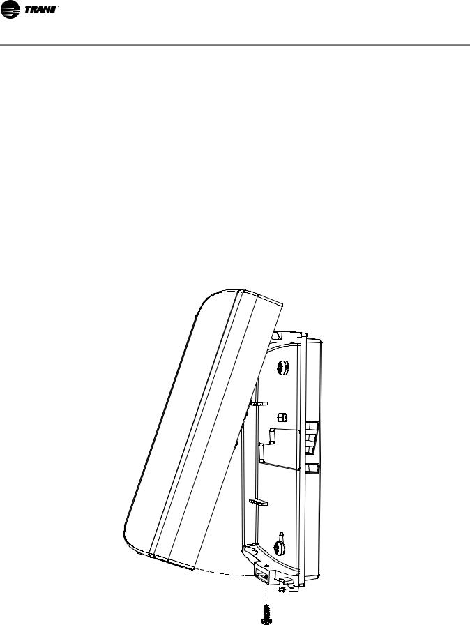
Replacing and Securing the Receiver Cover
1.To replace the receiver cover on the base plate, hook the cover over the top of the base plate. Apply light pressure to the bottom of the cover until it snaps in place.
2.If necessary to keep the cover securely attached, install the security screw into the bottom of the receiver (Figure 10, p. 26).
Figure 10. Snap receiver cover on base plate and attach security screw
Security screw
26 |
VAV-SVX07A-EN |

VAV Start Up/Check Out Procedure
Applying Power to the Receiver
Restore power to the unit controller. Observe LED5 on the receiver (Figure 11, p. 27). It will light and stay constantly On when 24 V power is normal.
Figure 11. LED5 stays on after applying power to the receiver
 LED5 stays constantly On
Receiver Indicates Readiness to Associate
After initial power up, the receiver conducts a channel scan for 10 seconds. During this time, the receiver selects from 16 available channels the clearest channel on which to operate. LED1, LED2, and LED3 flash rapidly in succession while the channel scan is in progress.
Note: Do not attempt association until the channel scan is finished. After the channel scan is finished, LED3 will begin blinking (one-blink pattern) to show that the receiver is ready to be associated with a sensor. LED3 will stop blinking when association has been established (Figure 12, p. 27).
Figure 12. LED3 blinks when the receiver is ready to be associated with a sensor
RECEIVER
LED3
LED3 will begin to blink after 10 seconds
VAV-SVX07A-EN |
27 |

VAV Start Up/Check Out Procedure
Powering the Sensor and Associating the Sensor to the Receiver
1.Verify that the sensor is set to the same address as the receiver it is to be associated with.
2.Remove the insulation barrier, which is a plastic strip located between the two batteries (Figure 13, p. 28). Association will automatically occur between the sensor and the receiver. If the first association attempt is unsuccessful, the sensor will automatically reattempt association with the receiver every 10 minutes.
Note: A disassociated sensor will transmit an association request every 10 minutes. An associated sensor that has lost communication with the receiver will transmit an association request every 50 minutes.
Note: LED3 on the receiver stops blinking to indicate that association has been established.
Figure 13. Removing the insulation barrier on the sensor
SENSOR
B1 + |
+ |
|
Pb
Pb-FREE
LED1
LED2
LED3
|
|
|
S1 |
|
S2 |
SIGNAL |
|
||||
LED5
ADDRESS
LED5 


BATTERY
STATUS
J1
S3


 LED4
LED4 


STATUS +
S4
WIRELESS
INSTALL
–
B2 - |
S5
28 |
VAV-SVX07A-EN |
VAV Start Up/Check Out Procedure
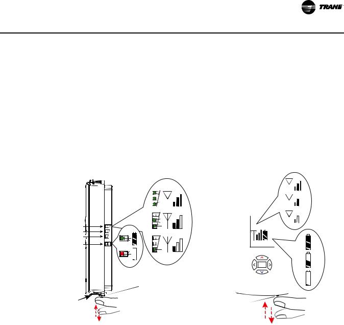
Testing Signal and Battery Strength
The following recommended test indicates signal and battery strength. It verifies that the association process was successful and that the batteries have adequate charge. (For more information on LEDs, see "Troubleshooting" chapter.)
1.Firmly press and release the Test button (S5) on the bottom of the sensor (Figure 14, p. 29).
2.View LED1, LED2, and LED3 to determine the strength of the signal. View LED5 to determine the strength of the battery.
Note: The LEDs will turn Off after 5 seconds to conserve battery strength.
3.Record the results in your commissioning statement.
Figure 14. Wireless sensors
Model WTS and WZS sensors |
|
|
|
Model WDS sensors |
||||||||||||||||||
|
|
|
|
|
|
|
|
|
|
|
|
|
|
|
|
|
|
|
|
|
|
|
|
|
|
|
|
|
|
|
|
|
|
|
|
|
|
|
|
|
|
|
|
|
|
|
|
|
|
|
|
|
|
|
|
|
|
|
|
|
|
|
|
|
|
|
|
|
|
|
|
|
|
|
|
|
|
|
|
|
|
|
|
|
|
|
|
|
|
|
|
|
|
|
|
|
|
|
|
|
|
|
|
|
|
|
|
|
|
|
|
|
|
|
|
|
|
|
|
|
|
|
|
|
|
|
|
|
|
|
|
|
|
|
|
|
|
LED1
LED2
LED3 
LED5
|
Test button |
|
Test button |
Push firmly, |
Push firmly, |
then release |
|
|
then release |
Disassociation
The receiver removes all stored association information, conducts a channel scan, and restarts itself, if any of the following are true:
•The receiver address is changed from its current setting (001-999).
•The receiver receives a disassociation notification from its associated sensor.
•The receiver does not receive a communication from its associated sensor within 35 minutes.
Configuring the Wireless Sensor (Model Digital Display WDS only)
The configuration of the sensor determines which system features can be accessed and changes can be made by the tenant (for example, changes to cooling/heating mode, setpoint, or fan speed. Verify system and associated unit features before configuring the sensor.
VAV-SVX07A-EN |
29 |
Loading...