


MUA-DS-5
MUA-DS-5
January 1998
Second Printing
Outdoor Gas Heating Units and Duct Furnaces
Packaged Rooftop Unit for Heating, Cooling, Ventilating and Make-Up Air Applications
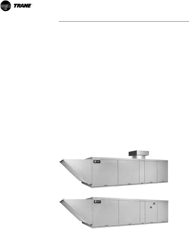
The Trane rooftop line is a packaged air heating and cooling system, suitable for heating, cooling, ventilating
and makeup air applications. Unit sizes range from 800 to 14,000 cfm (0.4-6.6 cu. m/s) with 1/2-15 hp motor capabilities. These rooftops are available with inputs from 100,000 Btu/h to 1,200,000 Btu/h (29.3 to 351.4 kW).
Duct furnaces are AGA and CGA certified for safety and performance with a range of 100,000 Btu/h input to 400,000 Btu/h (29.3 to 117.1 kW) input per duct furnace. Packaged units are also ETL and CSA certified for electrical safety in compliance with UL-1995 Standard for HVAC equipment. The rooftop units can be ordered as individual duct furnaces only, heating with evaporative cooling or packaged heating and cooling systems.
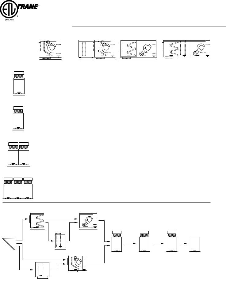
The mechanical configuration is determined by selecting one of the nine standard arrangements. Rooftop arrangements are divided into two classifications — standard and high cfm blower types.
The standard blower unit consists of a blower cabinet that houses the dampers, filters and blower in one cabinet. An optional evaporative cooling unit is available on units up to 800 MBh (234.3 kW). Trane recommends the use of 409 stainless steel whenever an evaporative cooling unit is installed upstream of a duct furnace section(s).
The high cfm blower unit utilizes a separate damper/filter cabinet with a “V” bank filter arrangement, a blower cabinet and up to three duct furnaces (1200 MBh) (351.4 kW). An optional cooling coil cabinet is offered on units up to 800 MBh. Trane recommends the use of 409 stainless steel whenever a cooling coil is used upstream of a furnace section(s). Both standard and high cfm blower arrangements may also include a downturn supply air plenum, outside air and/or return air, intake hood and a roof curb.
All units are completely packaged, railmounted, wired, piped, waterproofed and test fired to assure a smooth installation and easy start-up.
Features and Benefits
Furnace types are divided into two classifications — standard temperature rise and high temperature rise with natural and power vented models. All furnaces have optional left or right hand access. Standard temperature rise units have a lower pressure drop across the heat exchanger allowing higher airflow capabilities and an 80 percent efficiency rating with a temperature rise of 20 to 60 F (11 to 33 C). High temperature rise units are configured for higher temperature rise, and have a higher pressure drop across the furnace section of the unit and a 79 percent efficiency rating with a temperature rise of 60 to 90 F (33 to 50 C). The high temperature rise type furnace is not available in California and only available in a single furnace package. The maximum discharge air temperature for all duct furnaces is 150 F (66 C).
In addition to a versatile offering of mechanical features, this new rooftop unit also offers a wide variety of factory installed control options. Control components are located in the main electrical cabinet. The main electrical cabinet is located out of the air stream as part of the blower transition, between the blower cabinet and the first furnace for both standard and high cfm units. The standard electrical control scheme consists of a solid-state fan time delay, two pre-wired relay sockets which are mounted on the
unit’s main connection board, a solidstate gas ignition system and room or duct thermostats. The units are also equipped with a blower door safety interlock, a 24 VAC circuit breaker, a high temperature limit switch in each furnace section and a reverse airflow switch located in the blower cabinet as standard equipment.
Gas control options range from single stage to six stages of fire, mechanical or electronic modulation and direct digital control (DDC) interface. Air control options offer a similar range of control features from manual dampers to modulating dampers that may include mixed air, dry bulb, pressure sensing, enthalpy control, DDC interface or ASHRAE cycle control arrangements.
The venting is an integral part of the furnace and must not be altered in the field. The rooftop furnaces are equipped with a vent cap which is designed for gravity venting. Air for combustion enters at the base of the vent through a protective grill, and the design of the vent cap is such that the products of combustion are discharged at the upper section of the cap. This cap is shipped in a separate carton. It should be fastened in position and not be altered in any way.
Gravity Venting
Power Venting
©American Standard Inc. 1998
2

Contents
The proximity of the combustion air inlet to products of combustion discharge is designed to provide trouble-free operation under all types of wind conditions.
The power vented unit has a system with the inlet and discharge grill located in the upper section of a split-side panel. This balanced flue design also performs well under virtually all wind conditions.
Features and Benefits
•AGA and CGA Certified Duct Furnaces
•ETL and CSA UL-1995 Certified Packaged Units
•FM (Factory Mutual) Compliant
•Heating Capacities from 100 MBh to 1200 MBh (29.3 kW to 351.4 kW)
•Gravity and Power Vented Furnaces
•80% Efficient Standard Temperature Rise Furnace - 20 to 60 F (11 to 33 C) per Furnace
•79% Efficient High Temperature Rise Furnace - 60 to 90 F (33 to 50 C) - single furnace only
•CFM ranges from 800 to 14,000 CFM (0.4 to 6.6 Cu.m/s)
•Motor sizes up to 15 horsepower
•ODP motors with high efficiency, totally enclosed and two-speed options
•Left hand or right hand service access
•Draw-thru coil cabinet with stainless steel drain pan
•Evaporative cooling with standard 8 or optional 12” media (203 or 305 mm)
•Uninsulated or insulated roof curb
•Standard 18-gauge cabinets
•Standard 20-gauge aluminized steel heat exchanger. Optional stainless steel.
•Standard one-inch washable filters
•Standardvalve single stage combination gas
•Standard high temperature limit (each furnace)
•Standardswitch blower door safety interlock
•Standard reverse airflow safety switch
•Standard 24-volt circuit breaker
•Standard printed circuit main connection board
•Wiring harnesses with stamped wire numbers
•Solid-state automatic pilot ignition control
•Solid-state fan time delay
•Over 40 standard gas and air control packages
Features and Benefits |
2 |
|
|
Unit Configurations |
4 |
|
|
Model Number Description |
7 |
|
|
General Data |
9 |
|
|
Application Considerations |
11 |
|
|
Selection Procedure |
20 |
|
|
Performance Adjustment Factors |
26 |
|
|
Performance Data |
26 |
|
|
Electrical Data |
42 |
|
|
Controls |
43 |
|
|
Dimensional Data |
46 |
|
|
Weights |
100 |
|
|
Options |
102 |
|
|
Features Summary |
105 |
|
|
Mechanical Specifications |
106 |
3
Unit
Configurations
|
|
Unit Type |
Standard Features |
|
|
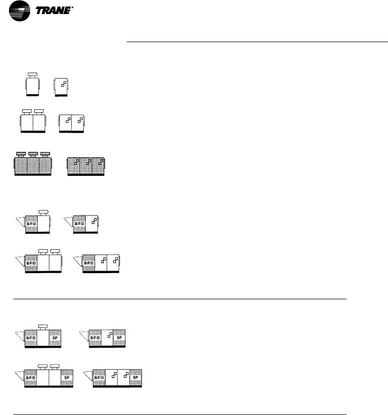
Arrangement A |
- Natural or LP (Propane Gas) |
|
|
Rooftop Duct Furnace |
- Single Stage 24-Volt Gas Valve |
|
|
|
- Intermittent Pilot Ignition |
|
|
|
|
|
|
|
- Orificed for Operation Up To 2000' Above Sea Level |
|
|
|
- Aluminized Steel Heat Exchanger |
|
|
|
- Flue Vent Cap (Gravity Vent Only) |
|
|
|
- 24-Volt High Temperature Safety Circuit |
|
|
|
- Terminal Block Wiring, Single Point Connection |
|
|
|
- Quick Opening Access Doors |
Arrangement B |
Same as Arrangement A with: |
Rooftop Heating Unit With Standard Blower |
- Insulated Blower/Filter/Damper Cabinet |
|
- 1” Permanent Filters |
|
- Fan Time Delay Relay |
|
- Electrical Cabinet Isolated from the Air Stream |
|
- 24-Volt Control Circuitry |
|
- Low Voltage Circuit Breaker |
|
- Blower Door Interlock Switch with Service Override |
Arrangement C
Rooftop Heating Unit with Standard Blower and Downflow Supply Plenum
Same as Arrangement B with: - Insulated Supply Plenum
See page 6 for Legend.
4
Unit
Configurations
Unit Type |
Standard Features |
|
|
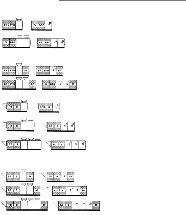
Arrangement D |
Same as Arrangement B with: |
|
|
Rooftop Heating Unit with Standard Blower |
- Evaporative Cooler |
|
|
and Evaporative Cooler |
- High Efficiency 8“ Media |
|
|
|
|
||
|
- Self-Cleaning Design |
|
|
|
- Sealed Pump Motor with Float Valve |
|
|
|
- 24-Volt Control Circuitry |
|
|
|
- Heavy-Duty Stainless Steel Water Tank |
|
|
|
- Easy Access Intake Filter and PVC Distribution Tubes |
|
|
Arrangement E |
|
Rooftop Heating Unit with Standard Blower, |
Same as Arrangement D with: |
Evaporative Cooler and Downflow Supply Plenum |
- Downflow Supply Plenum |
Arrangement G |
- Natural or LP (Propane Gas) |
Rooftop Heating Unit with High Cfm Blower |
- Single-Stage 24 Volt Gas Valve |
|
- Intermittent Pilot Ignition |
|
- Orificed for Operation up to 2000' above Sea Level |
|
- Aluminized Steel Heat Exchanger |
|
- Flue Vent Cap (Gravity Vent Only) |
|
- 24-Volt High Temperature Safety Circuit |
|
- Terminal Block Wiring, Single Point Connection |
|
- Quick Opening Access Doors |
|
- Permanent Filter |
|
- Fan Time Delay Relay |
|
- Standard V-bank Filter and Damper Cabinet |
|
- Insulated Filter/Damper and Blower Cabinet |
Arrangement J
Rooftop Heating Unit with High Cfm Blower and Downflow Supply Plenum
Same as Arrangement G with: - Insulated Supply Plenum
See page 6 for Legend.
5
Unit
Configurations
|
|
Unit Type |
Standard Features |
|
|
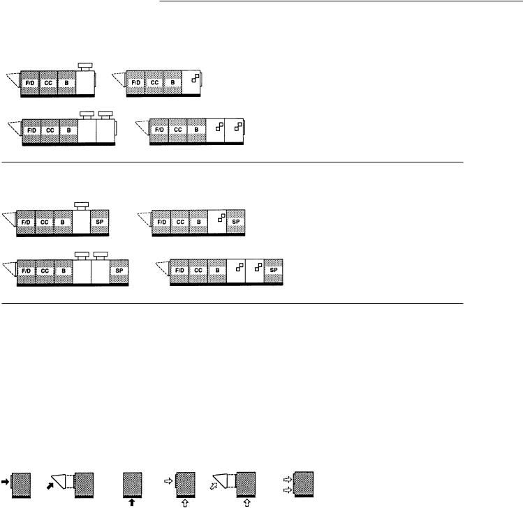
Arrangement K |
Same as Arrangement G with: |
|
|
Rooftop Heating Unit with High Cfm Blower |
- Coil Section |
|
|
and Coil Cabinet |
- Mounting for 4 to 6 Row Coils |
|
|
||
|
|
|
- Stainless Steel Drain Pan with 3/4” Tapped Outlets |
|
|
|
|
Arrangement L
Rooftop Heating Unit with High Cfm Blower, Coil Cabinet and Downflow Supply Plenum
Same as Arrangement K with: - Insulated Supply Plenum
Motors, Air Inlet Configuration/Air Control and Damper Arrangement Must Be Selected for Each Unit
Notes:
1.Gravity vent or power vent models available on all unit sizes.
2.Optional air inlet hood shown in dotted lines.
3.Legend is as follows:
B/F/D - Standard Blower/Filter/Damper
SP - Supply Plenum
EV - Evaporative Cooler
F/D - Filter/Damper
B - High cfm Blower
CC- Coil Cabinet
4.Horizontal outside air over return air. Specify air inlet configuration 4 or 5 and then select miscellaneous option “D” for horizontal return.
Air Inlet Configurations (Digit 18 of the Model Number)
1 |
2 |
3 |
4 |
5 |
See Note 4 Above |
6

Model
Number
Description
|
G R A A 40 G D C C 0 N 2 B Q 1 0 2 A 0 + |
|
||||||||
|
1 |
2 |
3 |
4 5,6 7 |
8 |
9 |
10 11 12 13 14 15 16 17 18 19 20 21 |
|
||
Digit 1 — Gas Heating Equipment |
Digit 9 — Gas Control Option (Intermittent |
Digit 14 — Rooftop Arrangements |
|
|||||||
G = Gas |
|
|
|
Pilot Ignition) |
|
|
A = Duct Furnace |
|
||
Digit 2 — Unit Type |
A = Single-Stage |
|
|
|
B = Blower (Standard) |
|
||||
B = Two-Stage |
|
|
|
C = Blower (Standard) Plenum |
|
|||||
F = Rooftop Duct Furnace |
C = Hydraulic Modulating (60-100) |
D = Blower (Standard) Evaporative Cooler |
|
|||||||
|
||||||||||
R = Rooftop Heating Unit |
D = Hydraulic Modulating (75-200) |
E = Blower (Standard) Evaporative Cooler/ |
|
|||||||
S = Special Unit Type |
E = Hydraulic Modulating With Bypass and |
|
Plenum |
|
||||||
Digit 3 — Furnace Type |
|
limit (60-100) |
|
|
|
G = Blower (High CFM) /Plenum |
|
|||
F = Hydraulic Modulating With Bypass |
J = Blower (High CFM) /Plenum |
|
||||||||
A = Standard Temp Rise (20-60 F) LH |
|
(75-200) |
|
|
|
K = Blower (High CFM) /Coil Cabinet |
|
|||
|
|
|
|
|
||||||
B = Standard Temp Rise (20-60 F) RH |
G = Electronic Modulating With Room |
L = Blower (High CFM) /Coil Cabinet/ |
|
|||||||
C = High Temp Rise (60-90 F) LH |
|
T-Stat |
|
|
|
|
|
Plenum |
|
|
D = High Temp Rise (60-90 F) RH |
H = Electronic Modulating With Duct T-Stat |
S = Special Rooftop Arrangement |
|
|||||||
S = Special Furnace Type |
J = Electronic Modulating With Duct T-Stat |
Digit 15 — Rooftop Heating Unit Motor |
|
|||||||
Note: LH = Left Hand |
|
and Override Room Thermostat |
|
|||||||
RH = Right Hand |
K = Electronic Modulating W/External |
|
Selection |
|
||||||
Digit 4 — Development Sequence |
|
4-20 mA Input (Furnace 1) |
0 |
= None (Rooftop duct furnace) |
|
|||||
L = Electronic Modulating W/External |
A |
= 1/2 HP w/contactor |
|
|||||||
A = First Generation |
|
4-20 mA Input (All furnaces) |
B |
= 3/4 HP w/contactor |
|
|||||
Digit 5,6 — Input Capacity |
M = Electronic Modulating W/External |
C |
= 1 HP w/contactor |
|
||||||
|
0-10 VDC Input (Furnace 1) |
D |
= 1 1/2 HP w/contactor |
|
||||||
Single Furnace |
N = Electronic Modulating W/External |
E |
= 2 HP w/contactor |
|
||||||
10 = 100 MBh Input |
|
0-10 VDC Input (All furnaces) |
F |
= 3 HP w/contactor |
|
|||||
15 = 150 MBh Input |
P = Two-Stage Discharge Air Control w/OA |
G |
= 5 HP w/contactor |
|
||||||
20 = 200 MBh Input |
|
Reset. |
|
|
|
|
H |
= 1/2 HP w/magnetic starter |
|
|
25 = 250 MBh Input |
R = Three-Stage Discharge Air Control |
J |
= 3/4 HP w/magnetic starter |
|
||||||
30 = 300 MBh Input |
|
w/OA Reset. |
|
|
|
K |
= 1 HP w/magnetic starter |
|
||
35 = 350 MBh Input |
T = Four-Stage Discharge Air Control w/OA |
L |
= 1 1/2 HP w/magnetic starter |
|
||||||
40 = 400 MBh Input |
|
reset. |
|
|
|
|
N |
= 2 HP w/magnetic starter |
|
|
Double Furnace |
U = S-350 2 Stage Modular Electronic |
P |
= 3 HP w/magnetic starter |
|
||||||
50 = 500 MBh Input |
|
Control System |
|
|
|
Q |
= 5 HP w/magnetic starter |
|
||
60 = 600 MBh Input |
W= S-350 3 Stage Modular Electronic |
R |
= 7 1/2 HP w/magnetic starter |
|
||||||
70 = 700 MBh Input |
|
Control System |
|
|
|
T |
= 10 HP w/magnetic starter |
|
||
80 = 800 MBh Input |
X = S-350 4 Stage Modular Electronic |
U |
= 15 HP w/magnetic starter |
|
||||||
Triple Furnace |
|
Control System |
|
|
|
S = Special Motor |
|
|||
12 = 1200 MBh Input |
Y = S-350 6 Stage Modular Electronic |
Digit 16 — Motor Speed |
|
|||||||
SS = Special unit |
|
Control System |
|
|
|
|
||||
Digit 7 — Venting Type |
S = Special Gas Control |
|
|
0 = No Selection |
|
|||||
Digit 10, 11 — Design Sequence |
1 = Single Speed ODP 1800 RPM |
|
||||||||
G = Gravity Venting |
2 = Single Speed TEFC 1800 RPM |
|
||||||||
P = Power Venting |
DO = Design Sequence |
|
|
3 = Single Speed High Efficiency ODP |
|
|||||
S = Special Venting |
Digit 12 — Fuel Type |
|
|
|
1800 RPM |
|
||||
Digit 8 — Main Power Supply |
|
|
4 = Single Speed High Efficiency |
|
||||||
N = Natural Gas |
|
|
|
|
TEFC 1800 RPM |
|
||||
A = 115/60/1 |
P = LP (Propane) Gas |
|
|
5 = 2S1W ODP 1800/900 RPM |
|
|||||
B = 208/60/1 |
L = Natural Gas with 100% Lockout |
6 = 2S2W ODP 1800/1200 RPM |
|
|||||||
C = 230/60/1 |
S = Special Fuel type |
|
|
S = Special Motor Speed & Starter |
|
|||||
D = 208/60/3 |
Digit 13 — Heat Exchanger Material |
Digit 17 — Coil Options |
|
|||||||
E = 230/60/3 |
|
|||||||||
F = 460/60/3 |
1 = Aluminized Steel |
|
|
0 |
= No cooling coil selection |
|
||||
G = 575/60/3 |
2 = #409 Stainless Steel (First Furnace Only) |
A |
= DX coil, 4 Row, Single Circuit |
|
||||||
S = Special Main Power Supply |
3 = #409 Stainless Steel (All Furnace |
B |
= DX coil, 4 Row, Dual Circuit |
|
||||||
|
|
Sections) |
|
|
|
C |
= DX coil, 6 Row, Single Circuit |
|
||
|
4 = #321 Stainless Steel (First Furnace Only) |
D |
= DX coil, 6 Row, Dual Circuit |
|
||||||
|
5 = #321 Stainless Steel (All Furnace |
E |
= Chilled Water Coil, 4 Row, |
|
||||||
|
|
Sections) |
|
|
|
G |
= Chilled Water Coil, 6 Row, |
|
||
|
6 = #409 Stainless Steel Package |
S = Special coil |
|
|||||||
|
|
(First Furnace Only) |
|
|
|
|
|
|||
7 = #409 Stainless Steel Package
(All Furnace Sections)
8 = #321 Stainless Steel Package
(First Furnace Only)
9 = #321 Stainless Steel Package
(All Furnace Sections)
S= Special Heat Exchanger Package
7

Model
Number
Description
Digit 18 — Air Inlet Configuration
0 = None (Rooftop Duct Furnace)
1 = Outside Air (OA) (Horizontal Inlet)
2 = Outside Air W/Air Hood (Horizontal Inlet
3 = Bottom Return Air (RA)
4 = Outside And Return Air (OA/RA)
5 = Outside and Return Air W/Air Hood S= Special Air inlet configuration
Digit 19 — Air Control and Damper Arrangement
0 = None (Rooftop Duct Furnace) A = Outside Air 2 pos. Motor/SR B = Return Air 2 pos. Motor/SR C = OA/RA 2 pos SR
E = OA/RA Mod Mtr W/Mixed Air Control/ Min Pot/SR
H = OA/RA Mod Mtr W/Mixed Air Control/ SR
K = OA/RA Mod Mtr W/Min Pot/SR
M = OA/RA Mod Mtr W/Dry Bulb/Mixed Air Control/Min Pot/SR
N = OA/RA Mod Mtr W/ Enthalpy
Controlled Economizer/SR
P = OA/RA Mod Mtr W/ Space Pressure Controller
R = OA/RA Mod Mtr W/ S-350 P Proportional Mixed Air Control/SR
U = OA/RA Mtr. W/External 0-10 VDC and 4-20 mA Analog Input/SR (External Input)
W= ASHRAE Cycle I (OA/RA 2 pos. w/ warm-up stat/SR
X = ASHRAE Cycle II (OA/RA Mod W/Warm-up Stat/Mixed Air/min pot/SR
Y = ASHRAE Cycle III (OA/RA Mod. W/Warm-up Stat/Mixed Air/SR
Z = Manual Dampers
S = Special Air Control and Damper Arrangement
Digit 20
0 = Non-California Shipment
1 = California Shipment
Digit 21 — Miscellaneous Options
A = Orifices For Elevation Above 2000 Feet
(Specify Elevation)
B = 12” Evaporative Media
C = Moisture Eliminators
D = Horizontal Return
E = Continuous Fan Relay
F = Freezestat
G = Fan Time Delay Control
(Duct Furnace Only)
H = Return Air Firestat
J = Supply Air Firestat
K = Manual Blower Switch
L = 409 Stainless Steel Furnace Drip Pan
N = Foil Face Insulation
P = Low Leak Dampers
Q = Clogged Filter Switch
R = High/Low Gas Pressure Limit Switches
T = Status Indicator Lamps (Elec Cabinet)
V = Manual Reset High LImit Switch
W= Interlock Relay —24/115V Coil
SPDT 10A
X = Interlock Relay —24/115-230V Coil
DPDT 10A
Y =Ambient Lockout
8
General
Data
|
|
|
|
Standard Blower |
Standard Blower w/Evap. |
|
High CFM Blower |
High CFM Blower w/Cooling |
|
|||||||||||||||
*The maximum CFM for |
Rooftop Arrangements B,C |
Rooftop Arrangements D,E |
|
Rooftop Arrangements G, J |
Rooftop Arrangements K,L*† |
|
||||||||||||||||||
|
Rooftop Arrangements |
|
|
|
|
|
|
|
|
|
|
|
|
|
|
|
|
|
|
|
|
|
|
|
|
K and L is 6,300 |
|
|
|
|
|
|
|
|
|
|
|
|
|
|
|
|
|
|
|
|
|
|
|
|
|
|
|
|
|
|
|
|
|
|
|
|
|
|
|
|
|
|
|
|
|
|
|
|
|
(3.0 m3/S). A two-speed |
|
|
|
|
|
|
|
|
|
|
|
|
|
|
|
|
|
|
|
|
|
|
|
|
motor may be utilized |
|
|
|
|
|
|
|
|
|
|
|
|
|
|
|
|
|
|
|
|
|
|
|
|
for non-cooling airflow |
|
|
|
|
|
|
|
|
|
|
|
|
|
|
|
|
|
|
|
|
|
|
|
|
up to 14,000 CFM |
|
|
|
|
|
|
|
|
|
|
|
|
|
|
|
|
|
|
|
|
|
|
|
|
|
|
|
|
|
|
|
|
|
|
|
|
|
|
|
|
|
|
|
|
|
|
|
|
|
|
|
|
|
|
|
|
|
|
|
|
|
|
|
|
|
|
|
|
|
|
|
|
|
|
(6.6 m3/S). |
|
|
|
|
|
|
|
|
|
|
|
|
|
|
|
|
|
|
|
|
|
|
|
|
Furnace Type A,B |
|
|
Capacity 10-40 |
Capacity 10-40 |
|
Capacity 20-40 |
Capacity 10-40 |
|
|||||||||||||||
|
T20 - 60F |
10 - 1,200-3,500 CFM, 1/2 - 5 HP |
10 -1,200-3,500 CFM, 1/2 - 5 HP |
20 -2,500-7,400 CFM, 3/4 - 10 HP |
10 -1,200-3,000 CFM, 1/2 - 5 HP |
|
||||||||||||||||||
|
|
15 - 2,000-4,500 CFM, 1/2 - 5 HP |
15 - 2,000-4,500 CFM, 1/2 - 5 HP |
25 - 3,100-7,500 CFM, 3/4 - 10 HP |
15 - 2,000-3,000 CFM, 1/2 - 5 HP |
|
||||||||||||||||||
|
|
20 - 2,500-5,500 CFM, 1/2 - 5 HP |
20 - 2,500-5,500 CFM, 1/2 - 5 HP |
30 - 3,700-11,00 CFM, 1/2 - 15 HP |
20 - 2,500-4,400 CFM, 3/4 - 10 HP |
|
||||||||||||||||||
|
|
25 - 3,000-5,500 CFM, 3/4 - 5 HP |
25 - 3,000-5,500 CFM, 3/4 - 5 HP |
35 - 4,500-13,000 CFM, 3/4 - 15 HP |
25 - 3,100-4,400 CFM, 3/4 - 10 HP |
|
||||||||||||||||||
|
|
30 - 3,700-7,000 CFM, 3/4 - 5 HP |
30 - 3,700-7,000 CFM, 3/4 - 5 HP |
40 - 5,000-14,000 CFM, 1 - 15 HP |
30 - 3,700-5,700 CFM, 1/2 - 15 HP |
|
||||||||||||||||||
|
|
|
||||||||||||||||||||||
|
|
35 - 4,500-8,500 CFM, 3/4 - 5 HP |
35 - 4,500-8,500 CFM, 3/4 - 5 HP |
|
|
|
|
|
|
35 - 4,500-5,700 CFM, 3/4 - 15 HP |
|
|||||||||||||
|
|
40 - 5,000-8,500 CFM, 1 - 5 HP |
40 - 5,000-8,500 CFM, 1 - 5 HP |
|
|
|
|
|
|
40 - 5,000-6,300 CFM, 1 - 15 HP |
|
|||||||||||||
|
|
ESP .1 - 2 in. WC |
ESP .1 - 2 in. WC |
ESP .1 - 2 in. WC |
ESP .1 - 2 in. WC |
|
|
|||||||||||||||||
|
Furnace Type C,D |
|
|
Capacity 10-40 |
Capacity 10-40 |
|
NA |
Capacity 20-40 |
|
|||||||||||||||
|
|
|
|
|||||||||||||||||||||
|
T60 - 90F |
10 - 800-1,200 CFM, 1/2 - 1 1/2 HP |
10 - 800-1,200 CFM, 1/2 - 1 1/2 HP |
|
|
|
|
|
|
20 - 1,600-2,400 CFM, 1/2 - 2 HP |
|
|||||||||||||
|
|
15 - 12,000-1,800 CFM, 1/2 - 2 HP |
15 - 12,000-1,800 CFM, 1/2 - 2 HP |
|
|
|
|
|
|
25 - 2,000-3,000 CFM, 1/2 - 2 HP |
|
|||||||||||||
|
|
20 - 1,600-2,400 CFM, 1/2 - 2 HP |
20 - 1,600-2,400 CFM, 1/2 - 2 HP |
|
|
|
|
|
|
30 - 2,400-3,600 CFM, 1/2 - 5 HP |
|
|||||||||||||
|
|
25 - 2,000-3,000 CFM, 1/2 - 3 HP |
25 - 2,000-3,000 CFM, 1/2 - 3 HP |
|
|
|
|
|
|
35 - 3,000-4,200 CFM, 1/2 - 5 HP |
|
|||||||||||||
|
|
30 - 2,400-3,600 CFM, 1/2 - 5 HP |
30 - 2,400-3,600 CFM, 1/2 - 5 HP |
|
|
|
|
|
|
40 - 3,300-5,000 CFM, 1/2 - 5 HP |
|
|||||||||||||
|
|
35 - 2,800-4,200 CFM, 1/2 - 5 HP |
35 - 2,800-4,200 CFM, 1/2 - 5 HP |
|
|
|
|
|
|
|
|
|
|
|
|
|
|
|||||||
|
|
40 - 3,200-4,800 CFM, 1/2 - 5 HP |
40 - 3,200-4,800 CFM, 1/2 - 5 HP |
|
|
|
|
|
|
|
|
|
|
|
|
|
|
|||||||
|
|
ESP .1 - 2 in. WC |
ESP .1 - 2 in. WC |
|
|
|
|
|
|
ESP .1 - 2 in. WC |
|
|||||||||||||
|
|
|
|
|
|
|
|
|
|
|
|
|
|
|
|
|
|
|
||||||
|
Furnace Type A,B |
|
|
Capacity 50-80 |
Capacity 50-80 |
|
Capacity 50-80 |
Capacity 50-80 |
|
|||||||||||||||
|
T40 - 120F |
50 - 3,000-3,500 CFM, 1 - 5 HP |
50 - 3,000-3,500 CFM, 1 - 5 HP |
50 - 3,100-7,500 CFM, 1 - 10 HP |
50 - 3,000-4,400 CFM, 1 - 10 HP |
|
||||||||||||||||||
|
|
60 - 3,700-6,500 CFM, 1 - 5 HP |
60 - 3,700-6,500 CFM, 1 - 5 HP |
|
60 - 3,700-11,000 CFM, 3/4 - 15 HP |
60 - 3,700-5,700 CFM, 3/4 - 15 HP |
|
|||||||||||||||||
|
|
70 - 4,500-8,000 CFM, 1 - 5 HP |
70 - 4,500-8,000 CFM, 1 - 5 HP |
|
70 - 4,500-13,000 CFM, 1 - 15 HP |
70 - 4,500-5,700 CFM, 1 - 15 HP |
|
|||||||||||||||||
|
|
80 - 5,000-8,000 CFM, 1 - 5 HP |
80 - 5,000-8,000 CFM, 1 - 5 HP |
|
80 - 5,000-13,500 CFM, 1 - 15 HP |
80 - 5,000-6,300 CFM, 1 - 15 HP |
|
|||||||||||||||||
|
|
ESP .1 - 2 in. WC |
ESP .1 - 2 in. WC |
ESP .1 - 2 in. WC |
ESP .1 - 2 in. WC |
|
||||||||||||||||||
|
|
|
|
|
|
|
|
|
|
|
|
|
|
|
|
|
|
|||||||
|
Furnace Type A,B |
|
|
NA |
NA |
|
Capacity 12 |
NA |
|
|||||||||||||||
|
T60 - 180F |
|
|
|
|
|
|
|
|
|
12 - 5,500-13,000 CFM, 1 1/2 - 15 HP |
|
|
|
|
|
|
|
|
|||||
ESP .1 - 2 in. WC
†These minimum and maximum CFM’s shown are for Arrangements K and L in the cooling mode. See Performance Data for heating mode specifications.
Damper/Filters |
Blower/Main Electrical |
|
|
|
|
(High CFM) |
(High CFM) 0-15 HP |
|
|
|
|
Intake Hood |
Coil Cabinet |
|
|
|
|
(High CFM) |
|
|
Furnace Three |
Supply Plenum |
|
|
Furnace One |
Furnace Two |
|||
|
|
||||
|
|
|
Furnace Type A-B |
Furnace Type A-B |
|
|
|
|
Arrangement B-E |
Arrangement G-J Only |
|
|
|
|
Arrangement G-L |
|
|
|
Dampers/Filters/Blower/Main |
|
|
|
|
|
Electrical |
|
|
|
|
Evaporative Cooler |
(Standard) 0-5 HP |
|
|
|
|
(Standard) |
|
|
|
|
|
9

General
Data
Table G-1 — Filter Data
Rooftop |
|
|
Unit Size |
|
Arrangement |
10,15 |
20,25,50 |
30,35,60,70 |
40,80,12 |
B-E |
(4)16 x 20 |
(4)20 x 20 |
(4)16 x 20 |
(6)20 x 20 |
|
|
|
(2)20 x 20 |
|
G-L |
(8)16 x 20 |
(8)20 x 20 |
(8)16 x 20 |
(12)20 x 20 |
|
|
|
(4)20 x 20 |
|
Table G-2 — Metric Conversion Table
Unless otherwise specified, the following conversions may be used for calculating SI unit measurements:
|
|
1 cubic foot= 0.028 m3 |
1 inch water column = 0.029 kPa |
|
|
1 foot = 0.0305 m |
1 gallon = 3.785 L |
|
|
1 inch = 25.4 mm |
1,000 Btu/Cu. Ft. = 37.5 MJ/m3 |
|
|
1 psig = 6.894 kPa |
1 liter/second = CFM x 0.472 |
|
|
1 pound = 0.453 kg |
1 meter/second = FPM ÷ 196.8 |
|
|
||
|
|
1,000 Btu per hour = 0.293 kW |
|
|
|
|
|
10
Application
Considerations
General
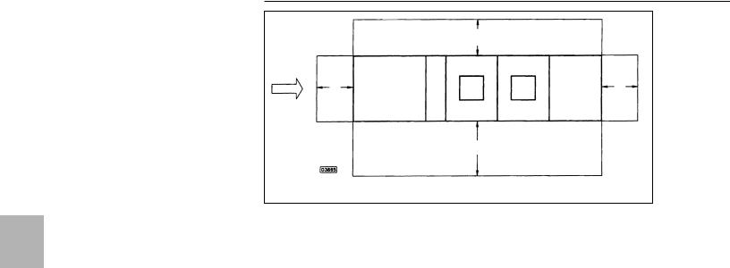
Outdoor duct furnaces are designed for use in ducted applications with a separate air handling device such as a horizontal blower assembly. By utilizing a separate air source, greater application flexibility in airflow delivery can be obtained. Multiple duct furnaces can be used with an air handling unit to provide zone heating.
|
FURNDUCT |
To Zone |
|
|
No. 1 |
||
Air |
DUCT |
To Zone |
|
Handling |
|||
FURN |
No. 2 |
||
Unit |
|||
|
|
||
|
DUCT |
To Zone |
|
|
FURN |
No. 3 |
Note: When installing duct furnaces in parallel or in series, minimum clearance requirements must be considered. This clearance is required for serviceability. Duct furnaces are approved for blow-thru applications only. Right-hand burner drawers are available for parallel applications. Contact your local Trane representative for more information.
When used in conjunction with filters, cooling coils and an air handler, the duct furnace can become part of a builtup heating and cooling system.
Filter |
Fan |
Duct |
Cooling |
|
|||
|
Supply |
Furnace |
Coil |
Outdoor heating units are designed for make-up air or space heating applications. These weatherproofed units are intended for roof or slab mounting, saving indoor space and offering easy access for service and maintenance. The units are typically used in ducted applications.
Outdoor units cannot be mounted indoors due to the flue configuration.
Gas Heating Value
The majority of gas heating units are installed in applications where natural gas is readily available. In areas where natural gas is not available, Trane units may be ordered directly from the factory for use on LP (propane) gas.
Gas heat content varies by fuel type and location. The standard gross heating value for natural gas is 1,000 Btuh per cubic foot; for propane it is 2,500 Btuh per cubic foot. Significant variations from these standard values should be taken into account in equipment selections. To account for variations in the gross heating value of the fuel, adjust the total heat input required and select the unit on the basis of the adjusted load using the following formula:
Adjusted load = Calculated load x Standard gross heat value (Btuh/cu ft) Actual gross heat value (Btuh/cu ft)
Low Temperature Rise
Trane recommends against the set-up of a unit which will result in a temperature rise of less than 20 F. With such low temperature rises, the flue gases passing through the heat exchanger are cooled to condensate before reaching the flue outlet. This condensate is corrosive and will result in shortened heat exchanger life.
Air Density
Catalog performance data is based on elevations up to 2,000 feet (610 m) above sea level. Above 2,000 feet (610 m), the unit’s heating capacity must be derated four percent for each 1,000 feet above sea level and special orifice selections are required. Table PAF-1 contains correction factors that can be applied to the unit’s cataloged heating capacity, fan rpm, and fan bhp to obtain actual values for elevations above 2,000 feet.
Corrosive Atmospheres
Corrosion of heat exchangers and draft diverters have two basic variables — moisture (condensation) and sulphur. These two ingredients form to make sulfuric acid in the combustion process. Condensation occurs commonly in make-up air systems, using large amounts of fresh air, when air temperatures entering the heat exchanger drop to 40 F or below. This reaction can also occur in recirculating systems where some quantity of
outside air is introduced upstream of the exchanger. The sulphur will always be present as an integral component of the gas. The resulting concentration of the acid is governed by the amount of sulphur in the gas. This concentration varies from gas to gas and geographically within the same type of gas.
Beyond sulfuric acid corrosion, there is the area of chlorinated or halogenated hydrocarbon vapor corrosion. This type of corrosion occurs when substances are mixed with combustion air that will cause the formation of hydrochloric or hydrofluoric acid when burned. These basic substances are found in degreasers, dry cleaning solvents, glues, cements, paint removers and aerosol propellants. Specific chemicals included in this group are trichloroethylene, perchloroethylene, carbon tetrachloride, methylene chloride, methyl chloroform and refrigerants 11, 12, 21, 22 and 114.
If sufficient PPM content of these corrosives is present, none of the common heat exchanger materials will hold up. The dilemma becomes whether to place the gas heating equipment outside of the area to be conditioned or use equipment in the space which does not burn a fuel such as gas (i.e., electric or hydronic).
Units should not be installed in areas with corrosive or inflammable atmospheres. Locations containing solvents or chlorinated hydrocarbons will produce corrosive acids when coming in contact with burner flames. This reaction will greatly reduce the life of the heat exchanger and may void the warranty. For added protection against heat exchanger corrosion, optional 409 and 321 stainless steel construction is available.
On units using outside air, with entering air temperature below 40 F, condensation of flue gas in the heat exchanger is possible. In these cases, stainless steel heat exchangers are recommended. An optional 409 or 321 stainless steel heat exchanger is recommended whenever there is an evaporative cooler or cooling coil upstream of the furnace section(s).
11
Application
Considerations
Careful review of the job application with respect to use, probable contaminants within a conditioned space and the amount of fresh air to be brought in will help to make the proper selection of heat exchanger material. This review will help to eliminate problems before they begin.
Outdoor gas heating products are used in either make-up air or space heating applications (constant volume or variable air volume). These two basic applications are discussed in detail below.
Make-Up Air Applications
Make-up air systems provide outside air for ventilation requirements and replace air removed by an exhaust air system. Typical applications include kitchens, restaurants, manufacturing areas, sports centers, garages and terminals.
Local codes and ordinances frequently specify ventilation requirements for public places and industrial installations. Generally accepted industry practices are given in the ASHRAE Handbook of Fundamentals. Published industrial ventilation codes are usually based on summer ventilation conditions of a work environment and should be reviewed for winter operation. Exhaust requirements should also be examined to establish the year-round make-up air requirement within limitations of codes and regulations. Whenever fresh air will be used and is present at temperatures below 40 F, 409 stainless steel heat exchangers are recommended.
18” (457 mm)
|
|
|
Cabinet |
Duct Furnace |
Duct Furnace |
|
|
|
|
|
|
||
AIR FLOW |
18” |
Blower |
Electrical |
|
Supply Plenum |
18” |
|
(457 mm) |
|
|
|
(457 mm) |
|
|
|
|
|
|
F*
*Refer to Outdoor Duct Furnace Manual for specific clearances.
Space Heating Applications — Constant Volume
Make-up air units can be used to offset a portion of the building heat losses in addition to supplying make-up air. This is accomplished by heating the makeup air beyond the required space temperature. The additional heat supplied above room temperature can satisfy a portion of the space heating requirement. The additional capacity (Btuh) available for heating can be calculated with the following equation:
Space Heating Capacity =
1.085 x SCFM Make-up Air x (Max T - (Troom - TO.A.))
Outdoor units using 100 percent return air or a combination of return and outside air are more efficient in providing space heat than make-up air units using 100 percent outside air at a colder temperature.
Space Heating Applications — Variable Air Volume
Dual duct VAV systems have one duct to distribute cold air to those spaces that need cooling and another to distribute warm air to those spaces that need heating. When separate fans are used to handle the two duct systems, the ductwork can be arranged to allow simultaneous use of airside economizers and plenum heat of lights. The cooling unit uses return air or cold outside air in order to save compressor energy. The heating unit uses only plenum heated return air. This return air contains the rejected heat from the lights in the building and when recovered through the heating unit, can lower gas heating costs.
In this mode, the dual duct VAV is not unlike water source heat pumps or three deck multizone air handlers, but also has the added savings of variable air volume.
Result — dual duct VAV is an efficient system capable of using economizers and heat recovery devices. Occupant comfort is enhanced because heating and cooling are always available to the perimeter zones.
12
Application
Considerations
General System Types
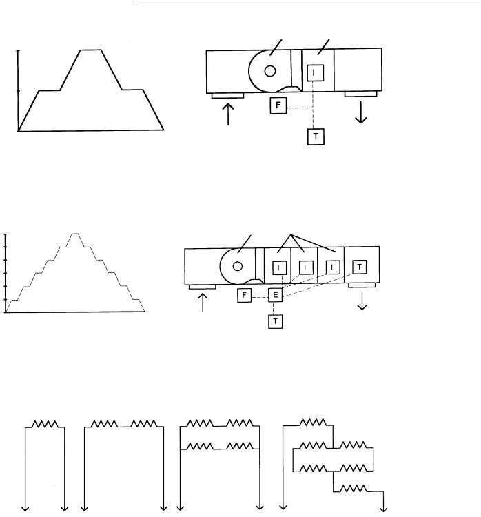
Single-Zone Staged Systems
100%
50%
0%
Stages of Fire
Single-zone staged systems can use multistage thermostats or ductstats for control of heating and cooling as well as multi-stage electronic controls. Systems need to be sized with respect
100%
85%
67%
50%
33%
17%
0%
Stages of Fire
Supply Fan Gas Fired Furnace
Return Air |
|
Supply Air |
|
T = Thermostat |
F = Fan Switch I = Ignition System |
|
|
to the heated space. Typical staged |
|
temperature with a differential setting |
|
|
|
||
single-zone heating is achieved with a |
for high and low fire. A fan time delay |
|
|
two-stage thermostat, delivering 50 |
|
relay provides fan control with a post |
|
percent of the units rated input at low |
warm-up delay period preventing |
|
|
fire and 100 percent at high fire. The |
|
discomfort in the space. |
|
|
|
||
thermostat is set to the desired space |
|
|
|
Supply Fan |
Gas Fired Furnace |
|
|
Return Air |
Supply Air |
T = Temperature Sensor |
F = Fan Switch |
I = Ignition System |
E = Electronic Control |
Electronic controls generally provide |
stage system equipped with an |
||
more stages of control with a higher |
electronic control system can deliver |
||
degree of precision in temperature |
16 percent of a units input at stage 1 |
||
sensing and actuation of stages. A six- |
(low fire), 33 percent at stage 2, |
||
1000 Ohms |
500 Ohms |
500 Ohms |
1000 Ohms 1000 Ohms |
|
|
|
1000 Ohms 1000 Ohms |
To |
To |
To |
Controller |
Controller |
Controller |
Direct |
Series |
Series/Parallel |
50 percent at stage 3, 66 percent at stage 4, 84 percent at stage 5 and 100 percent at stage 6 (high fire).
333.3Ohms
333.3Ohms 333.3 Ohms
333.3 Ohms
To
Controller
Series/Parallel
Large areas may incur hot and cold spots due to thermostat location, this can be overcome with electronic controls by incorporating within the
space a scheme of temperature averaging, by locating a number of series or series/paralleled temperature sensors such as thermisters, rtds or
prtd type sensors, an average temperature within the space can be transmitted to the control system.
13
Application
Considerations
|
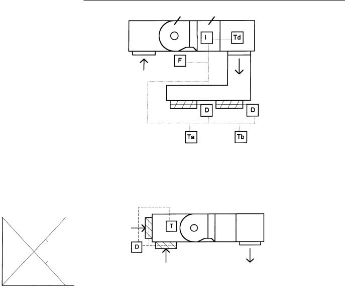
Multizone Staged Systems |
Supply Fan |
Gas Fired Furnace |
|
Multizone staged systems act on the |
|
|
|
same basic principals as a single-zone |
|
|
|
staged system where as each stage is |
|
|
|
engaged with respect to demand. With |
|
|
|
multizone systems a thermostat or |
|
|
|
zone sensor is used for each zone. The |
|
|
|
system must be sized to maintain |
|
|
|
comfort levels for all zones. Zone |
|
|
|
dampers are used for efficient |
Return Air |
|
|
operation of multizone systems. Upon |
|
|
|
a call for heat from either zone the |
|
|
|
system will fire at low fire, upon a call |
|
Supply Air |
|
from both zones the system will go to |
|
|
|
high fire. The zone dampers shall open |
|
|
|
and close upon a call for heat from |
Zone A |
Zone B |
|
their respective zone sensors. Typically |
|
|
|
|
|
|
|
a discharge air thermostat or sensor is |
|
|
|
used to maintain supply air |
|
|
|
temperature in multizone systems. |
Td = Discharge Air Temperature |
|
|
|
Ta/b = Temperature Sensor Zone A/B |
|
F = Fan Switch
I = Ignition System
D = Damper Actuator
Two Zone System
100% |
|
|
|
Damper |
|
Outside Air |
|
|
|
|
|
Percent |
|
|
|
Open |
Outside Air Damper |
|
|
50% |
|
|
|
|
|
|
|
|
Return Air Damper |
|
|
|
|
Return Air |
Supply Air |
|
|
T = Temperature Sensor |
|
0% |
|
D = Damper Actuator |
|
Interlocked Outside and Return Air Dampers |
Outside and Return Air Damper Arrangement |
||
Outside and Return Air Damper Control
Outside and return air damper control may be included in a staged single or multizone system. Interlocked outside and return air dampers with proportional actuator control, either electronic or electromechanical can maintain a minimum outside air setting and a mixed air setting. Damper control may also include enthalpy or pressure control.
14
Application
Considerations
Make-Up Air Systems
Supply Fan |
Exhaust Fan |
Outside Air
Exhaust Air
Return Air |
Supply Air |
Inside Air |
T = Temperature Sensor
D = Damper Actuator
P = Pressure Sensor
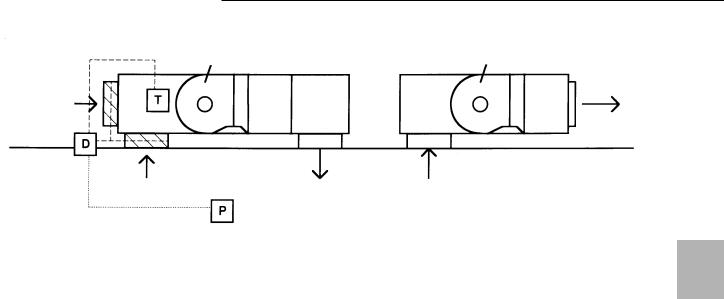
Rooftop Make-Up Air Unit with a Rooftop Exhaust Unit
Outside air is introduced in order to replace or make up for exhausted air due to commercial or industrial processes that require exhausted air within a space. The make up air is heated to a comfortable level relieving any additional load on the space heating system. Make-up air systems may also be configured to supplement space heating by increasing the discharge air temperature beyond the required temperature for the space. This additional heat above space temperature can offset a portion of the buildings heat losses. The additional heating capacity (Btuh) can be calculated as:
Space Heating Capacity = 1.085 x SCFM Make-Up Air x (Max T - (TROOM - TO.A.)).
Typical applications for make up air may include restaurants, kitchens, public arenas, airport and bus terminals, parking and maintenance garages, manufacturing and process areas. Make-up air and exhaust units may be matched in size and electrically interlocked with 100 percent outside air introduced when the exhaust fan is engaged. The make-up air system may also incorporate outside and return air and modulate the mixture based upon building pressure typically maintaining a slightly positive pressure within the space in order to reduce infiltration. The mixed air arrangement is generally the more efficient method due to the tempering of the outside air, however some applications may require 100 percent outside air due to poor return air quality. The use of 409 or 321 stainless steel heat exchangers is recommended whenever outside air is used.
15
Application
Considerations
Direct Digital Control (DDC) Systems
Damper |
|
Supply Fan |
|
Actuator |
Cooling |
Heating |
|
|
|
|
Discharge |
|
|
|
Air Sensor |
Outside Air |
|
|
|
Sensor |
|
|
|
|
Mixed Air |
|
|
|
Sensor |
|
|
Room Sensor
Communication
Via Modem
Digital Control Panel
Personal Computer
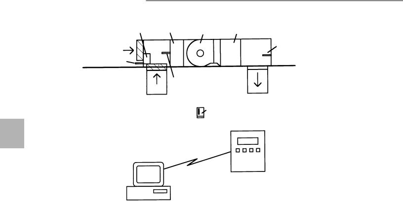
Basic DDC Control System with Heating/Cooling Rooftop Unit
The basic direct digital control (DDC) system uses a microprocessor based controller and software to perform system and building control functions. The controller receives input from sensors mounted within the system. Based upon input data, the controller outputs a programmed response to the system’s actuators (gas valves, fan motors and damper motors). Inputs may consist of temperature, pressure or flow and can be analog or digital signals. Output can also be analog or digital; analog output signals are generally 4-20 mA or 0-10 VDC and digital outputs a relay actuation.
The control may be located in the unit or in the building. A personal computer (PC) and software may be provided for remote communication. Temperature setpoints, night setback, time limited cycling, safety interlock input and system override functions may be setup at the controller or by PC interface via modem or direct connection. The controller may store in memory a number of previous cycles of operation with date, time, sensed temperatures, rate of fire and duration- of-cycle information available for down loading to a PC for report generation and printout. With digital control, energy use can be easily optimized for economical operation while maintaining comfort levels with a higher degree of accuracy.
Unit Placement
Refer to the applicable Trane Installation, Operation and Maintenance literature for specific installation instructions. Installations must conform with local building codes or, in the absence of local codes, with the National Fuel Gas Code ANSI Z223.1.
Outdoor units are designed and certified for outdoor use only. They may be located on the roof or at any convenient location outside the building to be heated. When locating units on the roof, make certain that it is capable of carrying the additional load of this equipment.
Units are mounted on skids and are suitable for curb or slab mounting. It is recommended that the unit’s skids be mounted either on solid planking or steel channels, but not on a soft tar roof where the skids could sink and reduce the clearance between the bottom of the unit and the roof.
16

Application
Considerations
Venting
The venting is an integral part of the furnace and must not be altered in the field. The rooftop furnaces are equipped with a vent cap which is designed for gravity venting. Air for combustion enters at the base of the vent through a protective grill, and the design of the vent cap is such that the products of combustion are discharged at the upper section of the cap. This cap is shipped in a separate carton. It should be fastened in position and not be altered in any way.
The proximity of the combustion air inlet to products of combustion discharge is designed to provide trouble-free operation under all types of wind conditions.
The power vented unit has a system with the inlet and discharge grill located in the upper section of a splitside panel. This balanced flue design also performs well under virtually all wind conditions.
FM and IRI Requirements
IRI, which stands for Industrial Risk Insurers, and FM, which stands for Factory Mutual, are both basically insurance companies which insure commercial/industrial firms against a variety of losses. Both publish requirements which must be met by certain equipment operating in the facilities they are preparing to insure.
Listed below is our interpretation of the requirements of both insurers pertaining to heating units only to the extent of features/controls required by IRI and/or FM. There are a number of additional requirements which pertain to electrical service, details of installation, etc., and we urge you to obtain copies of the publications pertaining to these details if you are involved in a job where IRI or FM adherence has been indicated. The requirements detailed herein are our interpretations of the latest publications in our possession and we must disclaim any responsibility for errors due to our interpretation and/or lack of any updated revision of these standards. Our intent is to provide you with an understanding of the application of these standards and how we believe our indirect-fired gas heating equipment applies.
IRI Requirements
1
All input sizes require 100 percent shutoff. This requires that any natural gas unit, equipped with intermittent pilot ignition, must employ a “lockout” type ignition system which will shut off pilot gas if the pilot fails to light at any time. This system is required by AGA on LP gas units as standard equipment. However, for natural gas units, you will need to specify fuel type “L” Natural Gas with 100 percent lockout.
2
All units require AGA certification or UL “listed” controls. Our units are AGA certified and meet this
requirement.
3
Models with inputs of 150,000 to 400,000 Btuh (43.9-117.1 kW) require “mechanical exhaust” and a “safety interlock.” For our units this means a power vented unit.
FM Requirements
1
All units must be AGA certified or UL listed. Our units are AGA certified.
2
The high limit control must be in a circuit, the voltage of which does not exceed 120 VAC. All of our high limits would meet this requirement.
The specific requirement for an “IRI or FM gas train,” while it applies to direct and indirect-fired gas heating equipment as well as oil-fired, comes into play only with units having an input in excess of 400,000 Btuh (117.1 kW). This may be one of the reasons why the majority of gas heating equipment manufacturers (indirectfired) limit their largest individual furnace to 400,000 Btuh (117.1 kW).
Minimum/Maximum Gas Inlet Pressures
Gas valves are suitable to a maximum inlet pressure of 0.5 psi (14 inches water column) on natural gas. If the main gas supply pressure is greater than 14 inches WC (3.5 kPa), a step down pressure regulator must be field installed ahead of the gas valve. Minimum inlet pressure for natural gas units is 6 1/2 inches W.C (1.6 kPa).
For LP (propane) gas, the minimum inlet pressure is 11 1/2 inches WC (2.9 kPa) and the maximum inlet pressure is 14.0 inches WC (3.5 kPa).
17

Application
Considerations
High Pressure Regulators — Natural Gas Only
The Trane gas heating products contained in this catalog are designed to operate at a pressure of 3.5-inch WC (0.9 kPa) (water column) when firing on natural gas. This is the “manifold” pressure or that which is present at the burner orifices. All five and six-function valves provide a built-in pressure regulator which is capable of reducing “supply” pressures from a maximum of 14-inch WC (3.5 kPa) (1/2 psi) down to 3.5-inch WC (0.9 kPa) on the leaving side of the valve. The valve typically “drops” about 1 1/2-inch so the minimum supply pressure is 5-inch WC.
Whenever supply pressures exceed 14-inch WC (3.5 kPa), a high pressure regulator should be selected. We supply an Equimeter regulator which is fitted with pressure springs and capacity orificing to meet the requirements of each specific job. In order to select the proper spring/orifice combination, we need to know what the supply pressure is on that particular job and the input size of the unit being ordered. More than one unit can be run from one regulator; however, we recommend that each unit have its own regulator.
We require that the “job” supply pressure be included on all jobs requiring high pressure regulators along with the unit size. The table that follows displays the regulator’s range as it pertains to inlet pressure and MBh. NA requires the customer to contact a local utility or an industrial supply house.
These devices are not available from Trane for LP gas. LP accessories must be secured from the gas supplier or industrial supply house.
18
Selection
Procedure
Quick Sizer Chart 1
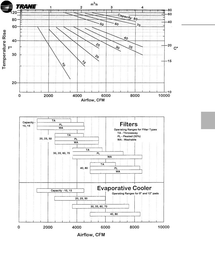
Furnace Type (A, B) Standard Temperature Rise Rooftop Arrangement (B, C, D, E)
19
Selection
Procedure
Quick Sizer Chart 2
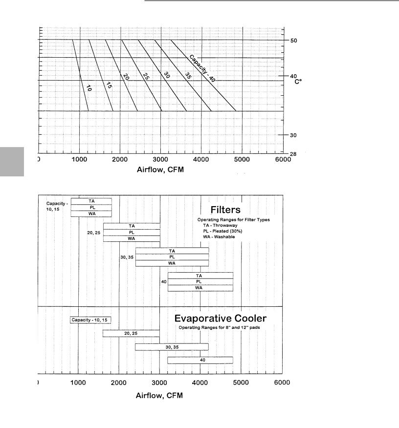
Furnace Type (C, D) High Temperature Rise Rooftop Arrangement (B, C, D, E)
20
Selection
Procedure
Quick Sizer Chart 3
Furnace Type (A, B) Low Temperature Rise Rooftop Arrangement (G, J, K, L)
21
Selection
Procedure
Quick Sizer Chart 4
Furnace Type (C, D) High Temperature Rise Rooftop Arrangement (G, J, K, L)
22
Selection
Procedure
Step 1
To properly select a unit, two of the three following items must be known: temperature rise (TR) required, cubic feet per minute of air delivery (cfm) required and output (Btu/h out) required. From any two of these items the third item can be determined, as well as the input (Btu/h In) required by using the following:
TR = BTU/H Out ÷ (1.085 x CFM) CFM = BTU/H ÷ (1.085 x TR) BTU/H Out = (CFM x 1.085) x TR
BTU/H In = BTU/H Out ÷ Efficiency
.80or.79
(The value 1.085 represents a constant.)
With any two of the three required values, match these requirements to a unit with the nearest input (Btu/h), temperature rise (TR) and airflow (cfm) capabilities keeping in mind that:
BTU/H Out = BTU/H In x Efficiency
Refer to the “Packaged Rooftop Arrangement Reference,” page 9, to match a capacity range (Btu/h), air delivery (cfm) and temperature rise (TR) with a rooftop arrangement.
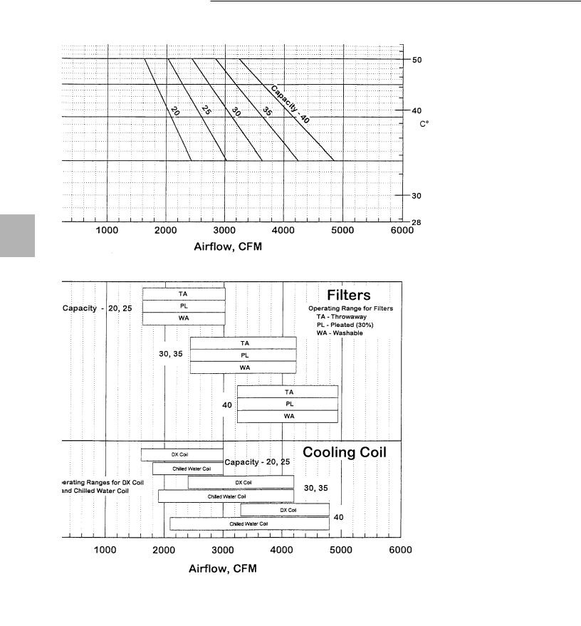
The top portion of Quick Sizer Charts 1, 2, 3 and 4 allows the use of temperature rise and cfm to determine capacity, or temperature rise and capacity to determine cfm, or capacity and cfm to determine temperature rise. Follow the top chart down to the corresponding filter and cooling range for the selection.
Step 2
Once capacity, temperature rise and cfm have been determined, go to the accessory pressure losses table for the arrangement and calculate pressure losses for unit accessories. Add the losses for filters, plenums, dampers, rainhood with screen or moisture eliminators, evaporative cooler or cooling coil and losses due to ductwork to determine the total esp.
Step 3A — 2000 ft. Altitude and Below
Refer to the performance table for the selection and determine rpm and bhp for the total external static pressure (esp). Go to the table row that most closely matches unit capacity, temperature rise and cfm, follow the row out to the column that equals the total esp for rpm and bhp values.
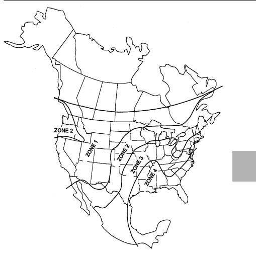
Figure SP-1 — Zone Chart
Step 3B — Above 2000 ft. Altitude
To correct for altitude, go to Table PAF-1, Correction Factors for Altitude. From this table, determine the correction factor from temperature and altitude for the system.
Correct the esp from ductwork to actual esp for altitude, then add sp from accessories as shown below. Refer to the performance table for the selected unit. Go to the row that most closely matches unit capacity, temperature rise and cfm, and follow the row out to the column that equals the corrected actual esp for rpm and bhp values. The bhp value can now be corrected to actual bhp for altitude as shown below.
Actual ESP = Duct ESP x Factor + Access. SP
Actual BHP = Cat. BHP ÷ Factor
Corrected BTUH Input = Catalog BTUH Input ÷ Factor
Corrected BTUH Output = Corrected BTUH Input x Efficiency
Performance
Evaporative cooling is most commonly used in areas where the relative humidity is low and the dry bulb temperatures are high. However, cooling through evaporation can be used in most areas.
Evaporative cooling is best utilized whenever the wet bulb depression (difference between dry and wet bulb temperature) is a minimum of 15 F.
The efficiency of the evaporative cooler is determined by a variety of factors: geographical location, application, air change requirements, sufficient water supply, airflow and maintenance. In most instances, efficiency is expected to be between 77 percent and 88 percent. Heat gains in the distribution system will affect the final output temperature.
Note: For SI metric conversion, see Table G-2 on page 10.
23
Selection
Procedure
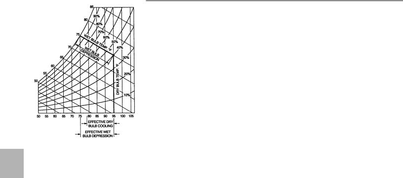
Figure SP-2 — Psychrometrics Chart
Use the psychrometric chart (shown in Figure SP-2) or actual humidity temperature readings to estimate the leaving dry bulb temperature at the outlet of the evaporative cooler.
Example:
Entering Dry Bulb: 95 F
Entering Wet Bulb: 75 F
Wet Bulb Depression (95 F - 75 F) = 20 F
Effective Wet Bulb Depression (20 F x .85) = 17 F
Leaving Dry Bulb Temperature (95 F - 17 F) = 78 F
Leaving Wet Bulb = Entering Wet Bulb = 75 F
Selection Method
The easiest method for selecting an evaporative cooler is to first determine the required number of air changes per minute.
1
Using Figure SP-1, choose the geographical zone in which the unit is
to be installed.
2
Determine the internal load within the structure:
Normal Load: structures with normal people loads, and without high internal heat gains.
High Load: Structures with high equipment loads (i.e. factories, laundromats, beauty salons, restaurant kitchens, etc.), and structures with high occupancy (night clubs, arenas, etc.).
3
Determine whether the structure has normal or high heat gains.
Normal Gain: Structures that have insulated roofs or are in shaded areas. Structures that have two or more stories or facing directions with no sun. High Gain: Structures that have uninsulated roofs, unshaded areas, or
rooms that are exposed to sun.
4
Using Table SP-1, determine the required air changes per minute based on zone selection and the type of heat load.
5
Finally, determine the air quantity for the space chosen, by calculating the volume (L x W x H). Multiply this volume by the air changes per minute.
Example:
Structure Dimensions:
25 L x 24 W x 10 H = 6000 Ft3 Exterior Load Type: Normal Interior Load Type: Normal Location: Dallas, Texas — Zone 3 Air Changes Per Minute: 3/4 Evaporative Cooler Requirements: 6000 Ft3 x 3/4 Air Change/Minute = 4500 CFM Required
See the evaporative cooler performance chart for unit size that would best apply.
Table SP-1 — Air Changes Per Minute
|
|
Zone |
|
|
Type Heat Load |
1 |
2 |
3 |
4 |
High Load/High Gain |
3/4 |
1 |
1 1/3 |
2 |
High Load/Normal Gain |
1/2 |
3/4 |
1 |
1 1/3 |
Normal Load/High Gain |
1/2 |
3/4 |
1 |
1 1/3 |
Normal Load/Normal Gain |
1/2 |
1/2 |
3/4 |
1 |
Cooling Coils
Cooling coils are used in air handling systems to cool and dehumidify an air stream for comfort purposes. To reduce the cooling load in buildings, most applications recirculate a large percentage of the air. Usually recirculated air is 75 to 80 percent of the airflow with the remainder being outside fresh air. Some codes require 100 percent outside air, particularly for hospitals and schools. Also many engineers specify higher percentages of outside air to meet the requirements of ASHRAE Standard 62-1989 “Ventilation for Acceptable Indoor Air Quality.”
1
In order to select the least expensive coil to meet the specific performance criteria, the following information is required:
-Unit size
-Airflow in SCFM or ACFM and altitude (see “Fan Selection at Altitude“)
-Entering air dry bulb and wet bulb temperatures based on ratio of outside to return air.
-Cooling load MBh (1000’s Btu/h) or leaving air wet bulb.
2
For chilled water coils, the following additional information is required.
-Fluid type: water, ethylene glycol, propylene glycol and percent of mixture.
-Entering fluid temperature — F
-Leaving fluid temperature — F or rate of flow GPM.
Chilled water catalog tables are based on:
45 F entering water temperature Entering air temperature of 80 F DB/67 F WB. Data is certified in accordance with ARI Standard 410. For other than these conditions, please consult the factory.
24

Selection
Procedure
3
For DX (refrigerant) coils thefollowing additional information is required:
-Refrigerant type
-Suction temperature — F
-Liquid temperature — F
-Type of circuiting desired
-Hot gas bypass required?
DX catalog tables are based on: 45 F suction temperature
Entering air temperature of 80 F DB/ 67 F WB
R-22 refrigerant
100 F liquid temperature
Data is certified in accordance with ARI Standard 410. For other than these conditions, please consult the
factory.
4
When specifying a coil, one of the most important pieces of information is the airflow in SCFM. As stated in the “Fan Selection at Altitude” section, SCFM means Standard CFM or air at a density of 0.075 lb./cu. ft. A fan must be selected using ACFM or ACTUAL CFM. A cooling coil or heating coil must be selected using SCFM. Up to an altitude of approximately 1,500 feet above sea level, very little error would be introduced in the selection of a cooling coil. For altitudes above 1,500 feet above sea level, the coil must be selected using SCFM. The relationship between ACFM and SCFM is shown by the following equation:
SCFM = ACFM x (Actual Density ÷ 0.075)
The term “0.075 ÷ Actual Density” is referred to as the density correction factor, herein called the “Factor.” This factor can be found in Table PAF-1. The previous equation can then be rewritten as:
SCFM = (ACFM ÷ Factor)
Example: A cooling coil must be selected at 5,000 ft. altitude. The unit delivers 10,000 ACFM. What is the SCFM? At 5,000 ft. altitude, the factor from Table PAF-1 is 1.20, therefore:
SCFM = 10,000 ACFM ÷ 1.20 =
8.333 SCFM
5
The entering air temperatures, both wet bulb and dry bulb, must also be considered when selecting a coil. A majority of units usually use recirculated air with a percentage of outside air. The cooling coil must be selected using the mixed air temperature entering the coil.
The following example shows how to calculate the mixed air temperature:
25 percent outside air at 95 F DB/
75 F WB
75 percent recirculated air at 78 F DB/
67 F WB
The mixed dry bulb is simply the proportional value between the outside and recirculated dry bulb temperatures.
.25 x 95 + .75 x 78 = 82.3 F
The mixed wet bulb temperatures must be calculated using either the humidity ratio from a psychrometric chart or from Table SP-2, The enthalpy of saturated air at various wet bulb temperatures.
Using Table SP-2, the enthalpy of the outside air at 75 F WB is 38.62 Btu/lb. and the recirculated air at 67 F WB is 31.63 Btu/lb., the mixed enthalpy is:
.25 x 38.62 + .75 x 31.63 = 33.38 Btu/lb.
Using this value in Table SP-2, the interpolated wet bulb temperature is 69.1 F.
So the final mixed temperatures are: 82.3 F DB/69.1 F WB
Table SP-2 — Enthalpy of Saturated Air at
Various Wet Bulb
Temperatures
Wet |
BTU |
Wet |
BTU |
|
|
Bulb |
per |
Bulb |
Per |
|
|
Temp. |
Pound |
Temp. |
Pound |
|
|
50 |
20.38 |
65 |
30.05 |
|
|
50.5 |
20.64 |
65.5 |
30.44 |
|
|
51 |
20.90 |
66 |
30.83 |
|
|
51.5 |
21.17 |
66.5 |
31.23 |
|
|
52 |
21.45 |
67 |
31.63 |
|
|
52.5 |
21.73 |
67.5 |
32.03 |
|
|
53 |
22.01 |
68 |
32.44 |
|
|
53.5 |
22.29 |
68.5 |
32.86 |
|
|
54 |
22.59 |
69 |
33.27 |
|
|
54.5 |
22.88 |
69.5 |
33.70 |
|
|
55 |
23.18 |
70 |
34.12 |
|
|
55.5 |
23.48 |
70.5 |
34.55 |
|
|
56 |
23.79 |
71 |
34.99 |
|
|
56.5 |
24.10 |
71.5 |
35.42 |
|
|
57 |
24.42 |
72 |
35.87 |
|
|
57.5 |
24.74 |
72.5 |
36.31 |
|
|
58 |
25.06 |
73 |
36.77 |
|
|
58.5 |
25.39 |
73.5 |
37.22 |
|
|
59 |
25.73 |
74 |
37.68 |
|
|
59.5 |
26.06 |
74.5 |
38.15 |
|
|
60 |
26.40 |
75 |
38.61 |
|
|
60.5 |
26.75 |
75.5 |
39.09 |
|
|
61 |
27.10 |
76 |
39.56 |
|
|
61.5 |
27.45 |
76.5 |
40.04 |
|
|
62 |
27.81 |
77 |
40.53 |
|
|
62.5 |
28.17 |
77.5 |
41.02 |
|
|
63 |
28.54 |
78 |
41.51 |
|
|
63.5 |
28.91 |
78.5 |
42.01 |
|
|
64 |
29.29 |
79 |
42.51 |
|
|
64.5 |
29.67 |
79.5 |
43.02 |
|
|
25

Performance
Adjustment
Factors
Table PAF-1 — Correction Factors for Altitude
|
|
|
|
|
|
Altitude (Feet) |
|
|
|
|
|
||
|
0’ |
500’ |
1000’ |
1500’ |
2000’ |
2500’ |
3000’ |
3500’ |
4000’ |
4500’ |
5000’ |
5500’ |
6000’ |
Temp. |
|
|
|
|
Barometric Pressure (In. Hg) |
|
|
|
|
||||
F |
39.92 |
29.38 |
28.86 |
28.33 |
27.82 |
27.31 |
26.82 |
26.32 |
25.84 |
25.36 |
24.9 |
24.43 |
29.98 |
-40 |
0.79 |
0.81 |
0.82 |
0.84 |
0.85 |
0.87 |
0.88 |
0.90 |
0.92 |
0.93 |
0.95 |
0.97 |
0.99 |
0 |
0.87 |
0.88 |
0.90 |
0.92 |
0.93 |
0.95 |
0.97 |
0.99 |
1.00 |
1.02 |
1.04 |
1.06 |
1.08 |
40 |
0.94 |
0.96 |
0.98 |
1.00 |
1.01 |
1.03 |
1.05 |
1.07 |
1.09 |
1.11 |
1.13 |
1.16 |
1.18 |
70 |
1.00 |
1.02 |
1.04 |
1.06 |
1.08 |
1.10 |
1.12 |
1.14 |
1.16 |
1.18 |
1.20 |
1.22 |
1.25 |
80 |
1.02 |
1.04 |
1.06 |
1.08 |
1.10 |
1.12 |
1.14 |
1.16 |
1.18 |
1.20 |
1.22 |
1.25 |
1.27 |
100 |
1.06 |
1.08 |
1.10 |
1.12 |
1.14 |
1.16 |
1.18 |
1.20 |
1.22 |
1.25 |
1.27 |
1.29 |
1.32 |
120 |
1.90 |
1.11 |
1.13 |
1.16 |
1.18 |
1.20 |
1.22 |
1.24 |
1.27 |
1.29 |
1.31 |
1.34 |
1.37 |
1.Actual ESP = Duct ESP x Factor ÷ Accs. SP
2.Actual BHP = Cat. BHP ÷ Factor
3.Correct BTUH Input = Catalog BTUH Input ÷ Factor
4.Corrected BTUH Output = Corrected BTUH Input x Efficiency
Performance
Data
|
|
Table PD-1 — Rooftop Gas Duct Furnace Performance Data — Arrangement A |
|
|
|
|
|
|||||||
|
|
|
|
|
|
|
|
|
|
|
|
|
||
|
|
|
Input |
Output |
|
Temp. Rise |
|
|
Pressure Drop |
|
|
|||
|
|
Capacity 10-12 |
Rating |
Rating |
|
|
Deg. F |
CFM |
in. of Water |
Nat. Gas |
L.P. Gas |
|||
|
|
Furnace Type A,B/C,D |
BTU/Hr |
BTU/Hr |
Eff. |
(Deg. C) |
(cu. m/s) |
(cu. m/s) |
(kPa) |
(kPa) |
Inlet |
Inlet |
||
|
|
Rooftop Arrangement “A” |
(kW) |
(kW) |
% |
Min. |
Max. |
|
Min. |
Max. |
Min. |
Max. |
in. |
in. |
|
|
10 A/B |
100,000 |
80,000 |
80 |
20 |
60 |
|
1,235 |
3,704 |
0.15 |
1.10 |
1/2 |
1/2 |
|
|
|
(29.3) |
(23.4) |
|
(11) |
(33) |
|
(0.583) |
(1.748) |
(0.04) |
(0.27) |
|
|
|
|
15 A/B |
150,000 |
120,000 |
80 |
20 |
60 |
|
1,852 |
5,556 |
0.15 |
1.00 |
1/2 |
1/2 |
|
|
|
(43.9) |
(35.1) |
|
(11) |
(33) |
|
(0.874) |
(2.622) |
(0.04) |
(0.25) |
|
|
|
|
20 A/B |
200,000 |
160,000 |
80 |
20 |
60 |
|
2,469 |
7,407 |
0.15 |
1.05 |
1/2 |
1/2 |
|
|
|
(58.6) |
(46.9) |
|
(11) |
(33) |
|
(1.165) |
(3.496) |
(0.04) |
(0.26) |
|
|
|
|
25 A/B |
250,000 |
200,000 |
80 |
20 |
60 |
|
3,086 |
9,259 |
0.15 |
1.08 |
3/4 |
1/2 OR 3/4 |
|
|
|
(73.2) |
(58.6) |
|
(11) |
(33) |
|
(1.457) |
(4.370) |
(0.04) |
(0.27) |
|
|
|
|
30 A/B |
300,000 |
240,000 |
80 |
20 |
60 |
|
3,704 |
11,111 |
0.15 |
1.10 |
3/4 |
1/2 OR 3/4 |
|
|
|
(87.8) |
(70.3) |
|
(11) |
(33) |
|
(1.748) |
(5.244) |
(0.04) |
(0.27) |
|
|
|
|
35 A/B |
350,000 |
280,000 |
80 |
20 |
60 |
|
4,321 |
12,963 |
0.15 |
1.11 |
3/4 |
1/2 OR 3/4 |
|
|
|
(102.5) |
(82.0) |
|
(11) |
(33) |
|
(2.040) |
(6.119) |
(0.04) |
(0.28) |
|
|
|
|
40 A/B |
400,000 |
320,000 |
80 |
20 |
60 |
|
4,938 |
14,815 |
0.15 |
1.12 |
3/4 |
1/2 OR 3/4 |
|
|
|
(117.1) |
(93.7) |
|
(11) |
(33) |
|
(2.331) |
(6.993) |
(0.04) |
(0.28) |
|
|
|
|
50 A/B |
500,000 |
400,000 |
80 |
40 |
120 |
|
3,086 |
9,269 |
0.30 |
2.16 |
3/4 |
1/2 OR 3/4 |
|
|
|
(146.4) |
(117.1) |
|
(22) |
(67) |
|
(1.457) |
(4.375) |
(0.07) |
(0.54) |
|
|
|
|
60 A/B |
600,000 |
480,000 |
80 |
40 |
120 |
|
3,704 |
11,111 |
0.30 |
2.20 |
3/4 |
1/2 OR 3/4 |
|
|
|
(175.7) |
(140.6) |
|
(22) |
(67) |
|
(1.748) |
(5.244) |
(0.07) |
(0.55) |
|
|
|
|
70 A/B |
700,000 |
560,000 |
80 |
40 |
120 |
|
4,321 |
12,963 |
0.30 |
2.22 |
3/4 |
1/2 OR 3/4 |
|
|
|
(205.0) |
(164.0) |
|
(22) |
(67) |
|
(2.040) |
(6.119) |
(0.07) |
(0.55) |
|
|
|
|
80 A/B |
800,000 |
640,000 |
80 |
40 |
120 |
|
4,938 |
14,815 |
0.30 |
2.24 |
3/4 |
1/2 OR 3/4 |
|
|
|
(234.3) |
(187.4) |
|
(22) |
(67) |
|
(2.331) |
(6.993) |
(0.07) |
(0.56) |
|
|
|
|
12 A/B |
1,200,000 |
960,000 |
80 |
60 |
180 |
|
4,938 |
14,815 |
0.45 |
3.36 |
3/4 |
1/2 OR 3/4 |
|
|
|
(351.4) |
(281.1) |
|
(33) |
(100) |
|
(2.331) |
(6.993) |
(0.11) |
(0.84) |
|
|
|
|
10 C/D |
100,000 |
79,000 |
79 |
30 |
90 |
|
823 |
2,469 |
0.10 |
0.88 |
1/2 |
1/2 |
|
|
|
(29.3) |
(23.1) |
|
(17) |
(50) |
|
(0.388) |
(1.165) |
(0.02) |
(0.22) |
|
|
|
|
15 C/D |
150,000 |
118,500 |
79 |
30 |
90 |
|
1,219 |
3,657 |
0.10 |
0.78 |
1/2 |
1/2 |
|
|
|
(43.9) |
(34.7) |
|
(17) |
(50) |
|
(0.575) |
(1.726) |
(0.02) |
(0.19) |
|
|
|
|
20 C/D |
200,000 |
158,000 |
79 |
30 |
90 |
|
1,626 |
4,876 |
0.10 |
0.81 |
1/2 |
1/2 |
|
|
|
(58.6) |
(46.3) |
|
(17) |
(50) |
|
(0.767) |
(2.301) |
(0.02) |
(0.20) |
|
|
|
|
25 C/D |
250,000 |
197,500 |
79 |
30 |
90 |
|
2,032 |
6,096 |
0.10 |
0.85 |
3/4 |
1/2 OR 3/4 |
|
|
|
(73.2) |
(57.8) |
|
(17) |
(50) |
|
(0.959) |
(2.877) |
(0.02) |
(0.21) |
|
|
|
|
30 C/D |
300,000 |
237,000 |
79 |
30 |
90 |
|
2,438 |
7,315 |
0.10 |
0.86 |
3/4 |
1/2 OR 3/4 |
|
|
|
(87.8) |
(69.4) |
|
(17) |
(50) |
|
(1.151) |
(3.453) |
(0.02) |
(0.21) |
|
|
|
|
35 C/D |
350,000 |
276,500 |
79 |
30 |
90 |
|
2,845 |
8,534 |
0.10 |
0.87 |
3/4 |
1/2 OR 3/4 |
|
|
|
(102.5) |
(81.0) |
|
(17) |
(50) |
|
(1.343) |
(4.028) |
(0.02) |
(0.22) |
|
|
|
|
40 C/D |
400,000 |
316,000 |
79 |
30 |
90 |
|
3,251 |
9,753 |
0.10 |
0.88 |
3/4 |
1/2 OR 3/4 |
|
|
|
(117.1) |
(92.5) |
|
(17) |
(50) |
|
(1.534) |
(4.603) |
(0.02) |
(0.22) |
|
|
Ratings shown are for elevations up to 2000 feet (610 m) above sea level. Above 2000 feet (610 m), input must be derated four percent for each 1000 feet (305 m) above sea level.
26

Performance
Data
Chart PD-1 — Duct Furnace Performance
Furnace Type — (A, B)
Standard Temperature Rise Duct Furnace Performance
Furnace Type — (A, B)
20-60 F Rise/Furnace
80% Efficiency
Chart PD-2 — Duct Furnace Performance
Furnace Type — (C, D)
High Temperature Rise Duct Furnace Performance
Furnace Type — (C, D)
60-90 F Rise/Furnace
79% Efficiency
27

Performance
Data
Table PD-2 — Rooftop Gas Heating Units Performance Data — Furnace Type (A,B) Standard Temperature Rise —
Rooftop Arrangement B,C,D,E
|
|
Capacity |
|
|
|
|
|
|
|
|
TOTAL EXTERNAL STATIC PRESSURE (INCHES OF WATER) |
|
|
|
|
|
||||||||||
|
|
Furnace |
TR |
|
Input |
Output |
0.2 |
0.4 |
0.6 |
0.8 |
1 |
|
1.2 |
1.4 |
1.6 |
1.8 |
|
2 |
||||||||
|
|
Type |
(F) |
CFM |
BTU/H |
BTU/H |
RPM BHP RPM BHP RPM BHP RPM BHP RPM BHP RPM BHP RPM BHP RPM BHP RPM BHP RPM BHP |
|||||||||||||||||||
|
|
|
61 |
1,200 |
100,000 |
80,000 |
575 |
0.16 |
705 |
0.23 |
825 |
0.31 |
940 |
0.4 |
1040 |
0.5 |
1135 |
0.6 |
1220 |
0.7 |
1300 |
0.8 |
1375 |
0.91 |
1440 |
1.02 |
|
|
|
49 |
1,500 |
|
|
655 |
0.26 |
765 |
0.35 |
870 |
0.44 |
965 |
0.54 |
1060 |
0.64 |
1150 |
0.75 |
1235 |
0.87 |
1315 |
0.99 |
1390 |
1.12 |
1460 |
1.24 |
|
|
10-A,B |
37 |
2,000 |
|
|
795 |
0.55 |
890 |
0.65 |
975 |
0.77 1055 |
0.88 1130 |
1 1205 |
1.12 1280 |
1.25 1355 |
1.39 1425 |
1.54 1490 |
1.68 |
|||||||
|
|
|
29 |
2,500 |
|
|
950 |
1.01 |
1030 |
1.12 |
1105 |
1.25 |
1175 |
1.39 |
1240 |
1.54 |
1305 |
1.68 |
1365 |
1.83 |
1425 |
1.98 |
1485 |
2.13 |
1545 |
2.29 |
|
|
|
25 |
3,000 |
|
|
1110 |
1.68 |
1175 |
1.82 |
1240 |
1.95 |
1305 |
2.1 1365 |
2.27 |
1420 |
2.44 |
1475 |
2.62 |
1530 |
2.79 |
1580 |
2.97 |
1635 |
3.14 |
|
|
|
|
21 |
3,500 |
|
|
1270 |
2.59 |
1330 |
2.77 |
1385 |
2.93 |
1440 |
3.08 |
1495 |
3.25 |
1550 |
3.43 |
1600 |
3.63 |
1650 |
3.83 |
1695 |
4.04 |
1745 |
4.25 |
|
|
|
55 |
2,000 |
150,000 120,000 |
685 |
0.44 |
785 |
0.54 |
880 |
0.63 |
965 |
0.75 |
1045 |
0.87 |
1120 |
0.98 |
1195 |
1.11 |
1270 |
1.24 |
1345 |
1.37 |
1415 |
1.52 |
|
|
|
|
44 |
2,500 |
|
|
805 |
0.78 |
890 |
0.91 |
970 |
1.04 |
1045 |
1.15 |
1120 |
1.28 |
1190 |
1.43 |
1255 |
1.57 |
1320 |
1.72 |
1380 |
1.86 |
1440 |
2.01 |
|
|
15-A,B |
37 |
3,000 |
|
|
935 |
1.28 1005 |
1.44 1075 |
1.6 1140 |
1.75 1205 |
1.88 1270 |
2.02 1335 |
2.18 1390 |
2.35 1450 |
2.53 1500 |
2.7 |
|||||||||
|
|
|
32 |
3,500 |
|
|
1065 |
1.97 |
1130 |
2.15 |
1190 |
2.33 |
1250 |
2.52 |
1305 |
2.7 1360 |
2.87 |
1420 |
3.02 |
1475 |
3.17 |
1525 |
3.35 |
1580 |
3.55 |
|
|
|
|
28 |
4,000 |
|
|
1200 |
2.88 |
1255 |
3.08 |
1310 |
3.28 |
1365 |
3.49 |
1415 |
3.7 1465 |
3.91 |
1515 |
4.12 |
1565 |
4.3 1615 |
4.48 |
1660 |
4.65 |
||
|
|
|
25 |
4,500 |
|
|
1340 |
4.04 |
1390 |
4.26 |
1435 |
4.49 |
1485 |
4.72 |
1530 |
4.95 |
|
|
|
|
|
|
|
|
|
|
|
|
|
59 |
2,500 |
200,000 160,000 |
555 |
0.44 |
650 |
0.55 |
740 |
0.66 |
820 |
0.78 |
895 |
0.89 |
965 |
1.02 |
1035 |
1.14 |
1105 |
1.28 |
1170 |
1.41 |
1230 |
1.56 |
|
|
|
|
49 |
3,000 |
|
|
630 |
0.71 |
710 |
0.83 |
790 |
0.96 |
865 |
1.1 |
935 |
1.23 |
1000 |
1.37 |
1065 |
1.52 |
1125 |
1.66 |
1180 |
1.81 |
1240 |
1.96 |
|
|
20-A,B |
37 |
4,000 |
|
|
790 |
1.58 |
855 |
1.72 |
915 |
1.86 |
975 |
2.03 1035 |
2.21 1090 |
2.39 1145 |
2.57 1200 |
2.76 1250 |
2.94 1300 |
3.13 |
||||||
|
|
|
29 |
5,000 |
|
|
965 |
2.98 |
1010 |
3.15 |
1060 |
3.32 |
1110 |
3.5 1160 |
3.7 1205 |
3.9 1255 |
4.12 |
1300 |
4.35 |
1345 |
4.57 |
1390 |
4.8 |
|||
|
|
|
27 |
5,500 |
|
|
1050 |
3.92 |
1095 |
4.11 |
1135 |
4.3 1180 |
4.49 |
1225 |
4.7 1270 |
4.91 |
|
|
|
|
|
|
|
|
||
|
|
|
61 |
3,000 |
250,000 200,000 |
615 |
0.69 |
695 |
0.8 |
775 |
0.93 |
850 |
1.07 |
920 |
1.21 |
985 |
1.34 |
1050 |
1.49 |
1110 |
1.63 |
1170 |
1.78 |
1225 |
1.93 |
|
|
|
|
53 |
3,500 |
|
|
690 |
1.05 |
760 |
1.17 |
830 |
1.31 |
900 |
1.46 |
965 |
1.62 |
1025 |
1.78 |
1085 |
1.94 |
1140 |
2.11 |
1195 |
2.27 |
1250 |
2.44 |
|
|
25-A,B |
46 |
4,000 |
|
|
770 |
1.53 |
830 |
1.66 |
895 |
1.81 |
955 |
1.97 1015 |
2.14 1070 |
2.32 1125 |
2.51 1180 |
2.69 1235 |
2.87 1285 |
3.06 |
||||||
|
|
|
41 |
4,500 |
|
|
855 |
2.13 |
905 |
2.29 |
960 |
2.44 |
1015 |
2.61 |
1070 |
2.79 |
1125 |
2.98 |
1175 |
3.19 |
1225 |
3.39 |
1275 |
3.6 1320 |
3.8 |
|
|
|
|
37 |
5,000 |
|
|
940 |
2.88 |
985 |
3.05 |
1030 |
3.23 |
1080 |
3.4 1130 |
3.59 |
1180 |
3.79 |
1230 |
4 |
1275 |
4.22 |
1320 |
4.45 |
1365 |
4.68 |
|
|
|
|
34 |
5,500 |
|
|
1025 |
3.8 1065 |
3.98 |
1110 |
4.17 |
1150 |
4.36 |
1195 |
4.56 |
1240 |
4.77 |
1285 |
4.98 |
|
|
|
|
|
|
|
|
|
|
60 |
3,700 |
300,000 240,000 |
655 |
0.73 |
760 |
0.91 |
860 |
1.11 |
945 |
1.32 |
1030 |
1.54 |
1110 |
1.76 |
1190 |
2.01 |
1270 |
2.26 |
1345 |
2.53 |
1415 |
2.81 |
|
|
|
|
55 |
4,000 |
|
|
690 |
0.89 |
790 |
1.09 |
885 |
1.28 |
970 |
1.51 |
1050 |
1.74 |
1125 |
1.98 |
1200 |
2.22 |
1275 |
2.48 |
1345 |
2.76 |
1415 |
3.05 |
|
|
30-A,B |
44 |
5,000 |
|
|
815 |
1.59 |
895 |
1.85 |
975 |
2.1 1055 |
2.32 1125 |
2.58 1195 |
2.88 1260 |
3.17 1325 |
3.46 1385 |
3.75 1445 |
4.05 |
|||||||
|
|
|
37 |
6,000 |
|
|
945 |
2.6 1015 |
2.91 |
1080 |
3.23 |
1150 |
3.53 |
1215 |
3.79 |
1280 |
4.07 |
1340 |
4.39 |
1400 |
4.74 |
|
|
|
|
|
|
|
|
34 |
6,500 |
|
|
1010 |
3.25 |
1075 |
3.58 |
1140 |
3.92 |
1200 |
4.26 |
1260 |
4.58 |
1320 |
4.86 |
|
|
|
|
|
|
|
|
|
|
|
32 |
7,000 |
|
|
1075 |
4 |
1140 |
4.35 |
1200 |
4.71 |
|
|
|
|
|
|
|
|
|
|
|
|
|
|
|
|
|
57 |
4,500 |
350,000 280,000 |
535 |
0.7 |
640 |
0.9 |
730 |
1.11 |
815 |
1.32 |
890 |
1.55 |
970 |
1.78 |
1040 |
2.02 |
1110 |
2.28 |
1175 |
2.55 |
1235 |
2.82 |
|
|
|
|
52 |
5,000 |
|
|
575 |
0.91 |
670 |
1.13 |
755 |
1.36 |
835 |
1.59 |
910 |
1.83 |
980 |
2.08 |
1050 |
2.33 |
1115 |
2.6 1180 |
2.88 |
1240 |
3.16 |
|
|
|
35-A,B |
43 |
6,000 |
|
|
650 |
1.48 |
735 |
1.72 |
810 |
1.99 |
880 |
2.26 |
950 |
2.54 1015 |
2.82 1080 |
3.1 1140 |
3.39 1195 |
3.69 1255 |
4 |
|||||
|
|
|
37 |
7,000 |
|
|
735 |
2.25 |
805 |
2.51 |
875 |
2.81 |
940 |
3.12 |
1000 |
3.44 |
1060 |
3.76 |
1120 |
4.09 |
1175 |
4.41 |
1230 |
4.74 |
|
|
|
|
|
|
|
|
|
||||||||||||||||||||
|
|
|
32 |
8,000 |
|
|
820 |
3.27 |
880 |
3.56 |
940 |
3.87 |
1000 |
4.21 |
1060 |
4.57 |
1115 |
4.94 |
|
|
|
|
|
|
|
|
|
|
|
30 |
8,500 |
|
|
860 |
3.88 |
920 |
4.18 |
980 |
4.51 |
1035 |
4.86 |
|
|
|
|
|
|
|
|
|
|
|
|
|
|
|
59 |
5,000 |
400,000 320,000 |
560 |
0.89 |
655 |
1.1 |
745 |
1.33 |
825 |
1.56 |
900 |
1.8 |
970 |
2.04 |
1040 |
2.3 1105 |
2.56 |
1170 |
2.84 |
1230 |
3.12 |
||
|
|
|
45 |
6,500 |
|
|
675 |
1.78 |
750 |
2.03 |
825 |
2.3 |
895 |
2.6 |
960 |
2.9 1025 |
3.2 1085 |
3.5 1145 |
3.8 1200 |
4.12 |
1255 |
4.44 |
||||
|
|
40-A,B |
42 |
7,000 |
|
|
715 |
2.19 |
785 |
2.44 |
855 |
2.73 |
920 |
3.04 |
985 |
3.36 1045 |
3.68 1105 |
4 1160 |
4.33 1215 |
4.66 1270 |
4.99 |
|||||
|
|
|
37 |
8,000 |
|
|
800 |
3.18 |
860 |
3.46 |
920 |
3.76 |
980 |
4.09 |
1040 |
4.45 |
1095 |
4.81 |
|
|
|
|
|
|
|
|
|
|
|
35 |
8,500 |
|
|
840 |
3.77 |
895 |
4.07 |
955 |
4.38 |
1015 |
4.72 |
|
|
|
|
|
|
|
|
|
|
|
|
|
|
|
123 |
3,000 |
500,000 400,000 |
645 |
0.73 |
730 |
0.85 |
805 |
0.99 |
880 |
1.12 |
950 |
1.26 |
1015 |
1.4 1075 |
1.55 |
1135 |
1.69 |
1195 |
1.84 |
1250 |
1.99 |
||
|
|
|
105 |
3,500 |
|
|
730 |
1.12 |
800 |
1.25 |
870 |
1.39 |
935 |
1.55 |
1000 |
1.71 |
1060 |
1.87 |
1115 |
2.03 |
1175 |
2.2 1225 |
2.36 |
1280 |
2.53 |
|
|
|
50-A,B |
92 |
4,000 |
|
|
815 |
1.63 |
875 |
1.77 |
940 |
1.92 1000 |
2.09 1055 |
2.27 1110 |
2.46 1165 |
2.64 1220 |
2.82 1270 |
3.01 1320 |
3.19 |
|||||||
|
|
|
82 |
4,500 |
|
|
900 |
2.27 |
955 |
2.43 |
1010 |
2.59 |
1065 |
2.77 |
1120 |
2.97 |
1170 |
3.17 |
1220 |
3.37 |
1270 |
3.58 |
1320 |
3.78 |
1365 |
3.99 |
|
|
|
74 |
5,000 |
|
|
990 |
3.07 |
1040 |
3.25 |
1085 |
3.42 |
1135 |
3.61 |
1185 |
3.81 |
1235 |
4.03 |
1280 |
4.25 |
1325 |
4.47 |
1370 |
4.7 1415 |
4.93 |
|
|
|
|
67 |
5,500 |
|
|
1080 |
4.05 |
1120 |
4.23 |
1165 |
4.43 |
1210 |
4.63 |
1255 |
4.84 |
|
|
|
|
|
|
|
|
|
|
|
|
|
120 |
3,700 |
600,000 480,000 |
700 |
0.82 |
805 |
0.99 |
900 |
1.2 |
985 |
1.42 |
1065 |
1.64 |
1145 |
1.87 |
1225 |
2.12 |
1305 |
2.38 |
1375 |
2.65 |
1450 |
2.94 |
|
|
|
|
111 |
4,000 |
|
|
740 |
1 |
840 |
1.18 |
930 |
1.4 1010 |
1.63 |
1090 |
1.86 |
1165 |
2.1 1240 |
2.36 |
1310 |
2.63 |
1385 |
2.91 |
1455 |
3.2 |
||
|
|
60-A,B |
88 |
5,000 |
|
|
880 |
1.79 |
960 |
2.05 1035 |
2.27 1110 |
2.53 1180 |
2.82 1250 |
3.11 1310 |
3.4 1370 |
3.69 1430 |
3.99 1490 |
4.29 |
||||||||
|
|
|
74 |
6,000 |
|
|
1025 |
2.95 |
1090 |
3.27 |
1155 |
3.57 |
1220 |
3.83 |
1285 |
4.11 |
1345 |
4.43 |
1405 |
4.78 |
|
|
|
|
|
|
|
|
|
68 |
6,500 |
|
|
1095 |
3.69 |
1160 |
4.03 |
1220 |
4.37 |
1280 |
4.67 |
1340 |
4.95 |
|
|
|
|
|
|
|
|
|
|
|
|
|
115 |
4,500 |
700,000 560,000 |
590 |
0.8 |
685 |
1.01 |
770 |
1.22 |
855 |
1.43 |
930 |
1.66 |
1005 |
1.9 1075 |
2.15 |
1140 |
2.41 |
1205 |
2.68 |
1265 |
2.96 |
||
|
|
|
103 |
5,000 |
|
|
630 |
1.04 |
720 |
1.27 |
805 |
1.5 |
880 |
1.74 |
950 |
1.98 |
1020 |
2.23 |
1090 |
2.49 |
1155 |
2.76 |
1215 |
3.05 |
1275 |
3.34 |
|
|
70-A,B |
86 |
6,000 |
|
|
720 |
1.68 |
800 |
1.95 |
870 |
2.22 |
940 |
2.5 1005 |
2.78 1070 |
3.06 1130 |
3.35 1190 |
3.65 1245 |
3.96 1300 |
4.27 |
||||||
|
|
|
74 |
7,000 |
|
|
815 |
2.55 |
885 |
2.85 |
950 |
3.17 |
1010 |
3.49 |
1070 |
3.81 |
1130 |
4.13 |
1185 |
4.46 |
1240 |
4.79 |
|
|
|
|
|
|
|
65 |
8,000 |
|
|
910 |
3.7 |
970 |
4.03 |
1030 |
4.38 |
1085 |
4.75 |
|
|
|
|
|
|
|
|
|
|
|
|
|
|
|
118 |
5,000 |
800,000 640,000 |
605 |
0.98 |
695 |
1.21 |
780 |
1.44 |
860 |
1.67 |
935 |
1.91 |
1005 |
2.16 |
1070 |
2.42 |
1135 |
2.69 |
1200 |
2.97 |
1260 |
3.26 |
|
|
|
80-A,B |
98 |
6,000 |
|
|
690 |
1.59 |
770 |
1.84 |
845 |
2.12 |
915 |
2.39 |
980 |
2.67 1045 |
2.95 1105 |
3.24 1165 |
3.53 1225 |
3.84 1280 |
4.15 |
|||||
|
|
|
84 |
7,000 |
|
|
780 |
2.41 |
850 |
2.7 |
915 |
3.01 |
980 |
3.33 |
1040 |
3.65 |
1100 |
3.97 |
1155 |
4.29 |
1210 |
4.62 |
1265 |
4.96 |
|
|
|
|
|
74 |
8,000 |
|
|
870 |
3.51 |
930 |
3.81 |
990 |
4.15 |
1050 |
4.51 |
1105 |
4.87 |
|
|
|
|
|
|
|
|
|
|
Notes:
1.Refer to Accessory Pressure Loss table.
2.Values are based on the “Basic Packaged Unit” which includes pressure drop of the duct furnace(s) and “system effect” of the blower module.
3.Brake horsepower (BHP) includes drive losses.
4.Unit leaving air temperature is limited to 150 F (66 C) and is equal to: Entering Air Temperature + Duct Furnace(s) Temperature Rise.
5.“Total External Pressure” is the sum of the unit’s “Internal” accessory pressure loss(es) plus the external static pressure.
6.Ratings shown are for elevations between 0 and 2000 ft. (610 m). For unit installation in the U.S.A. above 2000 ft. (610 m), the unit input must be derated 4% for each 1000 ft. (305 m) above sea level; refer to local codes, or in absence of local codes, refer to the National Fuel Gas Code, ANSI Standard Z223.1-1992 (N.F.P.A. No. 54), or the latest edition.
For installation in Canada, any references to deration at altitudes in excess of 2000 ft. (610 m) are to be ignored. At altitudes of 2000 to 4500 ft. (610 to 1372 m), the unit must be derated to 90% of the normal rating, and be so marked in accordance with the C.G.A. certification.
28

Performance
Data
Table PD-3 — Rooftop Gas Heating Units Performance Data — Furnace Type C,D — High Temperature Rise — Rooftop Arrangement B,C,D,E
Capacity |
|
|
|
|
|
|
|
|
TOTAL EXTERNAL STATIC PRESSURE (INCHES OF WATER) |
|
|
|
|
|
||||||||||
Furnace |
TR |
|
Input |
Output |
0.2 |
0.4 |
0.6 |
0.8 |
1 |
|
1.2 |
1.4 |
1.6 |
1.8 |
|
2 |
||||||||
Type |
(F) |
CFM |
BTU/H |
BTU/H |
RPM BHP RPM BHP RPM BHP RPM BHP RPM BHP RPM BHP RPM BHP RPM BHP RPM BHP RPM BHP |
|||||||||||||||||||
|
91 |
800 |
100,000 |
79,000 |
550 |
.09 |
710 |
.15 |
840 |
.22 |
950 |
.29 |
1045 |
.37 |
1135 |
.45 1210 |
.53 1285 |
.61 1355 |
.69 1420 |
.78 |
||||
|
81 |
900 |
|
|
575 |
.11 |
730 |
.18 |
855 |
.25 |
965 |
.33 |
1065 |
.41 1150 |
.50 1230 |
.58 1305 |
.67 1375 |
.76 1440 |
.86 |
|||||
10-C,D |
73 |
1,000 |
|
|
605 |
.14 |
745 |
.21 |
870 |
.29 |
980 |
.37 1080 |
.46 1165 |
.55 1245 |
.64 1320 |
.74 1390 |
.83 1455 |
.93 |
||||||
|
66 |
1,100 |
|
|
635 |
.17 |
770 |
.25 |
890 |
.33 |
995 |
.42 |
1095 |
.51 |
1180 |
.61 |
1260 |
.71 |
1335 |
.81 |
1410 |
.91 |
1475 |
1.01 |
|
61 |
1,200 |
|
|
670 |
.21 |
795 |
.29 |
910 |
.38 |
1015 |
.47 |
1110 |
.57 |
1195 |
.67 |
1280 |
.77 |
1355 |
.88 |
1425 |
.99 |
1490 |
1.10 |
|
91 |
1,200 |
150,000 |
118,500 |
580 |
.16 |
705 |
.23 |
830 |
.31 |
940 |
.40 |
1045 |
.50 |
1135 |
.60 |
1220 |
.70 |
1300 |
.80 |
1375 |
.91 |
1445 |
1.02 |
15-C,D |
78 |
1,400 |
|
|
630 |
.23 |
745 |
.31 |
855 |
.39 |
960 |
.49 1055 |
.59 1150 |
.70 1235 |
.81 1315 |
.93 1385 |
1.05 1460 |
1.17 |
||||||
|
68 |
1,600 |
|
|
685 |
.31 |
795 |
.40 |
890 |
.50 |
985 |
.60 |
1075 |
.70 |
1160 |
.82 |
1245 |
.94 |
1325 |
1.07 |
1400 |
1.19 |
1470 |
1.33 |
|
61 |
1,800 |
|
|
740 |
.42 |
845 |
.52 |
935 |
.62 |
1020 |
.73 |
1100 |
.84 |
1180 |
.96 |
1260 |
1.09 |
1340 |
1.22 |
1410 |
1.36 |
1480 |
1.50 |
|
91 |
1,600 |
200,000 |
158,000 |
500 |
.19 |
615 |
.26 |
720 |
.35 |
815 |
.44 |
900 |
.54 |
980 |
.64 |
1055 |
.76 |
1130 |
.88 |
1200 |
1.00 |
1270 |
1.13 |
|
81 |
1,800 |
|
|
530 |
.24 |
640 |
.33 |
735 |
.42 |
830 |
.51 |
915 |
.62 |
990 |
.73 1060 |
.84 1130 |
.96 1200 |
1.09 1265 |
1.23 |
||||
20-C,D |
73 |
2,000 |
|
|
560 |
.31 |
665 |
.41 |
755 |
.50 |
845 |
.60 |
925 |
.71 1000 |
.83 1075 |
.95 1140 |
1.07 1205 |
1.20 1265 |
1.34 |
|||||
|
66 |
2,200 |
|
|
595 |
.40 |
695 |
.50 |
780 |
.60 |
860 |
.71 |
940 |
.82 |
1015 |
.94 |
1085 |
1.07 |
1150 |
1.19 |
1215 |
1.33 |
1270 |
1.47 |
|
61 |
2,400 |
|
|
635 |
.49 |
725 |
.60 |
805 |
.71 |
885 |
.83 |
955 |
.95 |
1030 |
1.07 |
1095 |
1.20 |
1160 |
1.34 |
1225 |
1.48 |
1285 |
1.62 |
|
91 |
2,000 |
250,000 |
197,500 |
540 |
.30 |
645 |
.39 |
740 |
.48 |
825 |
.58 |
910 |
.69 |
985 |
.80 |
1060 |
.92 |
1125 |
1.05 |
1190 |
1.18 |
1250 |
1.31 |
|
81 |
2,250 |
|
|
580 |
.39 |
680 |
.50 |
765 |
.60 |
850 |
.71 |
925 |
.82 |
1000 |
.94 |
1070 |
1.07 |
1140 |
1.20 |
1200 |
1.33 |
1260 |
1.47 |
25-C,D |
73 |
2,500 |
|
|
625 |
.51 |
715 |
.63 |
795 |
.74 |
875 |
.86 |
945 |
.98 1015 |
1.10 1085 |
1.23 1150 |
1.37 1210 |
1.51 1270 |
1.66 |
|||||
|
66 |
2,750 |
|
|
665 |
.66 |
750 |
.78 |
830 |
.90 |
905 |
1.03 |
970 |
1.16 |
1035 |
1.29 |
1100 |
1.43 |
1160 |
1.57 |
1225 |
1.72 |
1280 |
1.87 |
|
61 |
3,000 |
|
|
710 |
.83 |
790 |
.96 |
865 |
1.10 |
935 |
1.23 |
1000 |
1.37 |
1065 |
1.51 |
1125 |
1.66 |
1180 |
1.81 |
1240 |
1.96 |
1295 |
2.12 |
|
91 |
2,400 |
300,000 |
237,000 |
585 |
.33 |
710 |
.47 |
835 |
.63 |
945 |
.81 |
1045 |
1.00 |
1140 |
1.20 |
1225 |
1.41 |
1305 |
1.62 |
1375 |
1.83 |
1445 |
2.05 |
|
81 |
2,700 |
|
|
625 |
.43 |
740 |
.58 |
850 |
.75 |
960 |
.94 |
1055 |
1.14 |
1150 |
1.36 |
1235 |
1.58 |
1315 |
1.80 |
1390 |
2.04 |
1460 |
2.27 |
30-C,D |
73 |
3,000 |
|
|
665 |
.54 |
775 |
.72 |
875 |
.90 |
975 |
1.09 1070 |
1.30 1160 |
1.53 1245 |
1.76 1325 |
2.00 1395 |
2.25 1470 |
2.50 |
||||||
|
66 |
3,300 |
|
|
705 |
.69 |
815 |
.87 |
905 |
1.07 |
1000 |
1.27 |
1085 |
1.49 |
1175 |
1.72 |
1255 |
1.97 |
1335 |
2.22 |
1405 |
2.48 |
1475 |
2.75 |
|
61 |
3,600 |
|
|
750 |
.86 |
850 |
1.05 |
940 |
1.26 |
1025 |
1.47 |
1110 |
1.70 |
1190 |
1.94 |
1270 |
2.20 |
1345 |
2.46 |
1415 |
2.74 |
1485 |
3.02 |
|
91 |
2,800 |
350,000 |
276,500 |
485 |
.30 |
610 |
.44 |
720 |
.60 |
815 |
.77 |
905 |
.96 |
990 |
1.17 |
1070 |
1.40 |
1145 |
1.63 |
1215 |
1.87 |
1280 |
2.12 |
|
82 |
3,100 |
|
|
510 |
.37 |
625 |
.52 |
730 |
.69 |
825 |
.87 |
910 |
1.07 |
990 |
1.28 |
1070 |
1.51 |
1140 |
1.75 |
1210 |
2.00 |
1280 |
2.26 |
35-C,D |
75 |
3,400 |
|
|
535 |
.46 |
645 |
.62 |
745 |
.79 |
840 |
.98 |
920 |
1.19 1000 |
1.40 1070 |
1.63 1140 |
1.88 1210 |
2.14 1275 |
2.41 |
|||||
|
69 |
3,700 |
|
|
560 |
.56 |
665 |
.73 |
760 |
.91 |
850 |
1.11 |
935 |
1.32 |
1010 |
1.55 |
1080 |
1.78 |
1145 |
2.03 |
1210 |
2.29 |
1275 |
2.57 |
|
64 |
4,000 |
|
|
590 |
.67 |
690 |
.86 |
780 |
1.05 |
865 |
1.26 |
945 |
1.48 |
1020 |
1.71 |
1090 |
1.95 |
1155 |
2.20 |
1220 |
2.47 |
1280 |
2.75 |
|
61 |
4,200 |
|
|
605 |
.76 |
705 |
.95 |
790 |
1.15 |
875 |
1.36 |
950 |
1.59 |
1025 |
1.82 |
1095 |
2.07 |
1160 |
2.33 |
1225 |
2.60 |
1285 |
2.88 |
|
91 |
3,200 |
400,000 |
316,000 |
500 |
.38 |
620 |
.53 |
725 |
.70 |
820 |
.88 |
905 |
1.08 |
985 |
1.29 |
1060 |
1.52 |
1130 |
1.76 |
1205 |
2.01 |
1270 |
2.28 |
|
81 |
3,600 |
|
|
535 |
.50 |
645 |
.66 |
740 |
.84 |
830 |
1.04 |
915 |
1.24 |
995 |
1.46 |
1065 |
1.69 |
1135 |
1.94 |
1200 |
2.20 |
1265 |
2.47 |
40-C,D |
73 |
4,000 |
|
|
570 |
.64 |
670 |
.82 |
760 1.01 845 1.22 930 |
1.43 1005 |
1.66 1075 |
1.90 1145 |
2.15 1205 |
2.42 1265 |
2.69 |
|||||||||
|
66 |
4,400 |
|
|
605 |
.80 |
700 |
1.01 |
785 |
1.21 |
865 |
1.43 |
945 |
1.66 |
1020 |
1.90 |
1090 |
2.15 |
1155 |
2.41 |
1215 |
2.68 |
1275 |
2.96 |
|
61 |
4,800 |
|
|
640 |
1.00 |
730 |
1.22 |
815 |
1.44 |
890 |
1.67 |
960 |
1.91 |
1035 |
2.16 |
1100 |
2.42 |
1165 |
2.69 |
1230 |
2.97 |
1285 |
3.26 |
Notes:
1.Refer to Accessory Pressure Loss table.
2.Values are based on the “Basic Packaged Unit” which includes pressure drop of the duct furnace(s) and “system effect” of the blower module.
3.Brake horsepower (BHP) includes drive losses.
4.Unit leaving air temperature is limited to 150 F (66 C) and is equal to: Entering Air Temperature + Duct Furnace(s) Temperature Rise.
5.“Total External Pressure” is the sum of the unit’s “Internal” accessory pressure loss(es) plus the external static pressure.
6.Ratings shown are for elevations between 0 and 2000 ft. (610 m). For unit installation in the U.S.A. above 2000 ft. (610 m), the unit input must be derated 4% for each 1000 ft. (305 m) above sea level; refer to local codes, or in absence of local codes, refer to the National Fuel Gas Code, ANSI Standard Z223.1-1992 (N.F.P.A. No. 54), or the latest edition.
For installation in Canada, any references to deration at altitudes in excess of 2000 ft. (610 m) are to be ignored. At altitudes of 2000 to 4500 ft. (610 to 1372 m), the unit must be derated to 90% of the normal rating, and be so marked in accordance with the C.G.A. certification.
29

Performance
Data
Table PD-4 — Rooftop Gas Heating Units Accessory Pressure Loss Data — Rooftop Arrangements B,C,D,E
|
|
|
|
|
|
|
|
Pressure Loss (Inches of Water) |
|
|
|
|||
|
|
|
|
Rainhood |
|
|
|
Filters |
|
|
Supply |
Evaporative |
Return or Outside |
|
|
|
|
|
With |
|
Throwaway |
Washable |
Pleated |
|
Air |
|
Media |
Air |
|
|
|
Capacity |
CFM |
Screen Mstr.Elim. |
2” |
1” |
2” |
1” |
2” |
Plenum |
8” |
12” |
Damper |
|
|
|
|
800 |
<.01 |
.01 |
.03 |
<.01 |
<.01 |
.03 |
.01 |
.02 |
.01 |
.02 |
.01 |
|
|
|
900 |
.01 |
.01 |
.03 |
<.01 |
<.01 |
.03 |
.02 |
.02 |
.02 |
.02 |
.02 |
|
|
|
1,100 |
.02 |
.02 |
.04 |
<.01 |
<.01 |
.04 |
.02 |
.03 |
.02 |
.04 |
.03 |
|
|
10 |
1,200 |
.02 |
.02 |
.05 |
<.01 |
<.01 |
.05 |
.03 |
.04 |
.03 |
.04 |
.03 |
|
|
|
1,500 |
.03 |
.04 |
.06 |
.01 |
.02 |
.07 |
.04 |
.06 |
.04 |
.07 |
.05 |
|
|
|
2,000 |
.05 |
.07 |
.09 |
.02 |
.03 |
.12 |
.07 |
.10 |
.08 |
.12 |
.09 |
|
|
|
2,500 |
.08 |
.11 |
.12 |
.03 |
.04 |
.17 |
.10 |
.15 |
.12 |
.18 |
.13 |
|
|
|
3,000 |
.11 |
.15 |
.16 |
.04 |
.06 |
.23 |
.14 |
.22 |
.17 |
.26 |
.19 |
|
|
|
3,500 |
.16 |
.21 |
.19 |
.06 |
.08 |
.30 |
.18 |
.29 |
.24 |
.35 |
.25 |
|
|
|
1,200 |
.02 |
.02 |
.05 |
<.01 |
<.01 |
.05 |
.03 |
.03 |
.03 |
.04 |
.03 |
|
|
|
1,400 |
.03 |
.03 |
.06 |
<.01 |
.01 |
.06 |
.03 |
.03 |
.04 |
.06 |
.04 |
|
|
|
1,600 |
.03 |
.04 |
.07 |
.01 |
.02 |
.08 |
.04 |
.04 |
.05 |
.07 |
.06 |
|
|
|
1,800 |
.04 |
.05 |
.08 |
.02 |
.02 |
.10 |
.05 |
.06 |
.06 |
.09 |
.07 |
|
|
15 |
2,000 |
.05 |
.07 |
.09 |
.02 |
.03 |
.12 |
.07 |
.07 |
.08 |
.12 |
.09 |
|
|
|
2,500 |
.08 |
.11 |
.12 |
.03 |
.04 |
.17 |
.10 |
.11 |
.12 |
.18 |
.13 |
|
|
|
3,000 |
.11 |
.15 |
.16 |
.04 |
.06 |
.23 |
.14 |
.15 |
.17 |
.26 |
.19 |
|
|
|
3,500 |
.16 |
.21 |
.19 |
.06 |
.08 |
.30 |
.18 |
.21 |
.24 |
.35 |
.25 |
|
|
|
4,000 |
.20 |
.27 |
|
.07 |
.11 |
.38 |
.23 |
.27 |
N/A |
N/A |
.33 |
|
|
|
4,500 |
.26 |
.34 |
|
.09 |
.14 |
|
|
.34 |
N/A |
N/A |
.42 |
|
|
|
1,600 |
.02 |
.02 |
.05 |
<.01 |
.01 |
.06 |
.03 |
.02 |
.02 |
.03 |
.03 |
|
|
|
1,800 |
.02 |
.03 |
.06 |
<.01 |
.01 |
.07 |
.04 |
.03 |
.02 |
.03 |
.03 |
|
|
|
2,000 |
.02 |
.03 |
.07 |
.01 |
.02 |
.08 |
.04 |
.03 |
.03 |
.04 |
.04 |
|
|
|
2,200 |
.03 |
.04 |
.08 |
.01 |
.02 |
.09 |
.05 |
.04 |
.03 |
.05 |
.05 |
|
|
20 |
2,400 |
.03 |
.05 |
.09 |
.02 |
.02 |
.11 |
.06 |
.05 |
.04 |
.06 |
.05 |
|
|
|
2,500 |
.04 |
.05 |
.09 |
.02 |
.03 |
.12 |
.07 |
.05 |
.04 |
.07 |
.06 |
|
|
|
3,000 |
.05 |
.07 |
.12 |
.03 |
.04 |
.16 |
.09 |
.07 |
.06 |
.10 |
.08 |
|
|
|
4,000 |
.09 |
.13 |
.17 |
.05 |
.07 |
.26 |
.16 |
.13 |
.11 |
.17 |
.15 |
|
|
|
5,000 |
.15 |
.20 |
|
.07 |
.11 |
.38 |
.23 |
.21 |
.18 |
.27 |
.23 |
|
|
|
5,500 |
.18 |
.25 |
|
.09 |
.13 |
.44 |
.28 |
.25 |
.22 |
.32 |
.28 |
|
|
|
2,000 |
.02 |
.03 |
.07 |
.01 |
.02 |
.08 |
.04 |
.02 |
.03 |
.04 |
.04 |
|
|
|
2,250 |
.03 |
.04 |
.08 |
.02 |
.02 |
.10 |
.05 |
.03 |
.04 |
.05 |
.05 |
|
|
|
2,500 |
.04 |
.05 |
.09 |
.02 |
.03 |
.12 |
.07 |
.04 |
.04 |
.07 |
.06 |
|
|
|
2,750 |
.04 |
.06 |
.10 |
.02 |
.03 |
.14 |
.08 |
.04 |
.05 |
.08 |
.07 |
|
|
|
||||||||||||
|
|
25 |
3,000 |
.05 |
.07 |
.12 |
.03 |
.04 |
.16 |
.09 |
.05 |
.06 |
.10 |
.08 |
|
|
|
4,000 |
.09 |
.13 |
.17 |
.05 |
.07 |
.26 |
.16 |
.09 |
.11 |
.17 |
.15 |
|
|
|
4,500 |
.12 |
.16 |
|
.06 |
.09 |
.31 |
.19 |
.12 |
.15 |
.22 |
.19 |
|
|
|
5,000 |
.15 |
.20 |
|
.07 |
.11 |
.38 |
.23 |
.14 |
.18 |
.27 |
.23 |
|
|
|
5,500 |
.18 |
.25 |
|
.09 |
.13 |
.44 |
.28 |
.17 |
.22 |
.32 |
.28 |
|
|
|
2,400 |
.02 |
.03 |
.06 |
.01 |
.01 |
.07 |
.04 |
.02 |
.03 |
.04 |
.03 |
|
|
|
2,700 |
.02 |
.03 |
.07 |
.01 |
.02 |
.09 |
.05 |
.03 |
.03 |
.05 |
.04 |
|
|
|
3,000 |
.03 |
.04 |
.08 |
.02 |
.02 |
.10 |
.06 |
.03 |
.04 |
.06 |
.05 |
|
|
|
3,300 |
.04 |
.05 |
.09 |
.02 |
.03 |
.12 |
.07 |
.04 |
.05 |
.07 |
.06 |
|
|
30 |
3,600 |
.04 |
.06 |
.10 |
.02 |
.03 |
.14 |
.08 |
.05 |
.06 |
.09 |
.07 |
|
|
|
4,000 |
.05 |
.08 |
.12 |
.03 |
.04 |
.17 |
.10 |
.06 |
.07 |
.11 |
.08 |
|
|
|
5,000 |
.09 |
.12 |
.16 |
.04 |
.06 |
.24 |
.14 |
.09 |
.11 |
.17 |
.13 |
|
|
|
6,000 |
.12 |
.17 |
|
.06 |
.09 |
.33 |
.20 |
.13 |
.16 |
.24 |
.19 |
|
|
|
6,500 |
.14 |
.20 |
|
.07 |
.11 |
.38 |
.23 |
.16 |
.19 |
.29 |
.22 |
|
|
|
7,000 |
.17 |
.23 |
|
.09 |
.13 |
.43 |
.27 |
.18 |
.22 |
.33 |
.25 |
30
 Loading...