


SIMATIC NET PROFIBUS
Table of contents
 Loading...
Symbols, Contents
PROFIBUS Networks
1
Topologies of SIMATIC NET PROFIBUS
Networks
2
Configuring Networks
3
Passive Components of RS–485 Networks
4
Active Components of RS–485 Networks
5
Passive Components for PROFIBUS–PA
6
Passive Components for Electrical Networks
7
Active Components for Optical Networks
8
Active Components for Wireless Networks
9
Testing PROFIBUS
A
Lightning and Surge Voltage Protection for
LAN Cables Between Buildings
B
Installing LAN Cables
C
Installing Instructions for SIAMTIC NET
PROFIBUS Plastic Fiber Optic with Simplex
Connenctors or BFOC Connectors and Pul-
ling Loop for the FO Standard Cable
D
Installing Network Components in Cubicles
E
Dimension Drawings
F
Operating Instructions ILM / OLM / OBT
G
General Information
H
References
I
SIMATIC NET – Support and Training
J
Glossary, Index
Manual
05/2000
6GK1970–5CA20–0AA1
Release 2
SIMATIC NET
PROFIBUS Networks

!
Danger
indicates that death, severe personal injury or substantial property damage will result if proper precau-
tions are not taken.
!
Warning
indicates that death, severe personal injury or substantial property damage can result if proper precau-
tions are not taken.
!
Caution
indicates that minor personal injury or property damage can result if proper precautions are not taken.
Note
draws your attention to particularly important information on the product, handling the product, or to a
particular part of the documentation.
Qualified Personnel
Only qualified personnel should be allowed to install and work on this equipment Qualified persons are
defined as persons who are authorized to commission, to ground, and to tag circuits, equipment, and sy-
stems in accordance with established safety practices and standards.
Correct Usage
Note the following:
!
Warning
This device and its components may only be used for the applications described in the catalog or the
technical description, and only in connection with devices or components from other manufacturers which
have been approved or recommended by Siemens.
This product can only function correctly and safely if it is transported, stored, set up, and installed cor-
rectly, and operated and maintained as recommended.
Trademarks
SIMATICR, SIMATIC HMIR and SIMATIC NETR are registered trademarks of SIEMENS AG.
HCS is a registered trademark of Ensign–Bickford Optics Company.
Third parties using for their own purposes any other names in this document which refer to trademarks
might infringe upon the rights of the trademark owners.
Safety Guidelines
We have checked the contents of this manual for agreement with the hard-
ware and software described. Since deviations cannot be precluded entirely,
we cannot guarantee full agreement. However, the data in this manual are
reviewed regularly and any necessary corrections included in subsequent
editions. Suggestions for improvement are welcomed.
Disclaimer of LiabilityCopyright Siemens AG 1999 All rights reserved
The reproduction, transmission or use of this document or its contents is not
permitted without express written authority. Offenders will be liable for
damages. All rights, including rights created by patent grant or registration of
a utility model or design, are reserved.
Siemens AG
Bereich Automatisierungs– und Antriebstechnik
Geschäftsgebiet Industrielle Kommunikation
Postfach 4848, D-90327 Nürnberg
E Siemens AG 1999
Subject to technical change.
Siemens Aktiengesellschaft Order no. 6GK 1970–5AC20–0AA1
i
PROFIBUS Networks SIMATIC NET
6GK1970-5CA20-0AA1 Release 2 05/2000
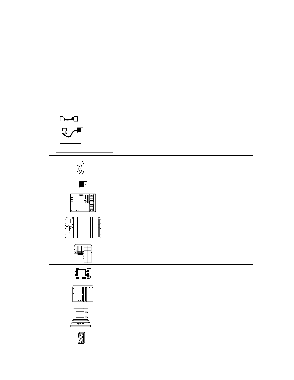
Symbols
PROFIBUS 830–1 T connecting cable
PROFIBUS 830-2 connecting cable
LAN cable (twisted-pair)
Duplex FO cable
Wireless transmission (infrared)
Bus connector
S7–300
S7–400
ET200S
OP25
ET 200M (with IM 153–2 FO)
PG/PC/OP
AS-i branch
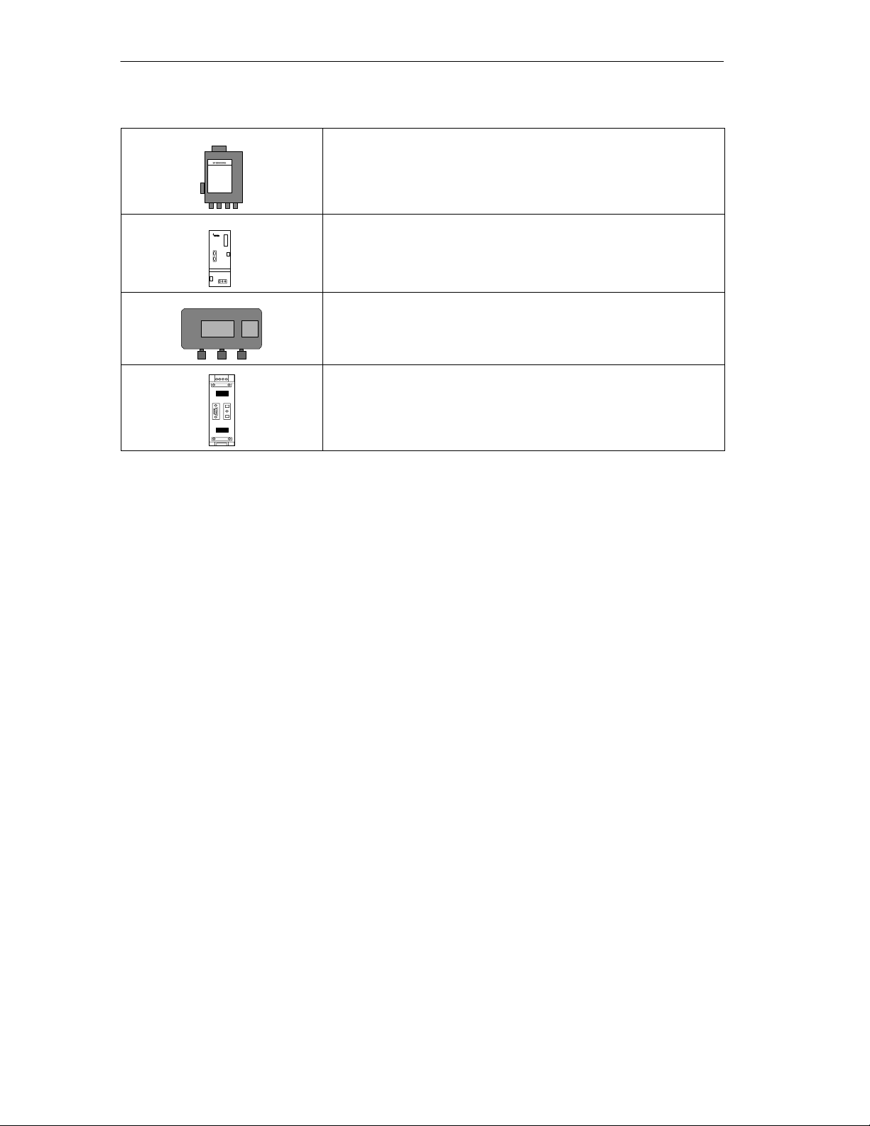
Symbols
ii
PROFIBUS Networks SIMATIC NET
6GK1970-5CA20-0AA1 Release 2 05/2000
Optical link module (OLM)
Optical bus terminal (OBT)
Infrared link module (ILM)
Repeater

Contents
iii
PROFIBUS Networks SIMATIC NET
6GK1970-5CA20-0AA1 Release 2 05/2000
Contents
1 PROFIBUS NETWORKS 1-1. . . . . . . . . . . . . . . . . . . . . . . . . . . . . . . . . . . . . . . . . . . . . . . . .
1.1 Local Area Networks in Manufacturing and Process Automation 1-2. . . . . . .
1.1.1 General Introduction 1-2. . . . . . . . . . . . . . . . . . . . . . . . . . . . . . . . . . . . . . . . . . . . .
1.1.2 Overview of the SIMATIC NET System 1-3. . . . . . . . . . . . . . . . . . . . . . . . . . . . .
1.2 Basics of the PROFIBUS Network 1-5. . . . . . . . . . . . . . . . . . . . . . . . . . . . . . . . .
1.2.1 Standards 1-7. . . . . . . . . . . . . . . . . . . . . . . . . . . . . . . . . . . . . . . . . . . . . . . . . . . . . .
1.2.2 Access Techniques 1-8. . . . . . . . . . . . . . . . . . . . . . . . . . . . . . . . . . . . . . . . . . . . . .
1.2.3 Transmission Techniques 1-9. . . . . . . . . . . . . . . . . . . . . . . . . . . . . . . . . . . . . . . . .
1.2.4 Transmission Techniques According to EIA Standard RS-485 1-10. . . . . . . . .
1.2.5 Transmission Techniques for Optical Components 1-12. . . . . . . . . . . . . . . . . . .
1.2.6 Transmission Technique for Wireless Infrared Technology 1-14. . . . . . . . . . . . .
1.2.7 Transmission Technique for PROFIBUS-PA 1-15. . . . . . . . . . . . . . . . . . . . . . . . .
2 Topologies of SIMATIC NET PROFIBUS Networks 2-1. . . . . . . . . . . . . . . . . . . . . . . . .
2.1 Topologies of RS-485 Networks 2-2. . . . . . . . . . . . . . . . . . . . . . . . . . . . . . . . . . .
2.1.1 Components for Transmission Rates up to 1.5 Mbps 2-3. . . . . . . . . . . . . . . .
2.1.2 Components for Transmission Rates up to
12 Mbps 2-4. . . . . . . . . . . . . . . . . . . . . . . . . . . . . . . . . . . . . . . . . . . . . . . . . . . . . . .
2.2 Topologies of Optical Networks 2-5. . . . . . . . . . . . . . . . . . . . . . . . . . . . . . . . . . . .
2.2.1 Topology with Integrated Optical Interfaces 2-6. . . . . . . . . . . . . . . . . . . . . . . . .
2.2.2 Topologies with OLMs 2-7. . . . . . . . . . . . . . . . . . . . . . . . . . . . . . . . . . . . . . . . . . . .
2.2.3 Combination of Integrated Optical Interfaces and OLMs 2-13. . . . . . . . . . . . . .
2.3 Topologies of Wireless Networks 2-14. . . . . . . . . . . . . . . . . . . . . . . . . . . . . . . . . .
2.4 Topologies with PROFIBUS-PA 2-17. . . . . . . . . . . . . . . . . . . . . . . . . . . . . . . . . . .
2.5 Connectivity Devices 2-20. . . . . . . . . . . . . . . . . . . . . . . . . . . . . . . . . . . . . . . . . . . . .
2.5.1 DP/DP Coupler 2-20. . . . . . . . . . . . . . . . . . . . . . . . . . . . . . . . . . . . . . . . . . . . . . . . .
2.5.2 Connecting to PROFIBUS-PA 2-22. . . . . . . . . . . . . . . . . . . . . . . . . . . . . . . . . . . . .
2.5.3 DP/PA Coupler 2-23. . . . . . . . . . . . . . . . . . . . . . . . . . . . . . . . . . . . . . . . . . . . . . . . . .
2.5.4 DP/PA Link 2-25. . . . . . . . . . . . . . . . . . . . . . . . . . . . . . . . . . . . . . . . . . . . . . . . . . . . .
2.5.5 Connecting PROFIBUS-DP to RS-232C 2-28. . . . . . . . . . . . . . . . . . . . . . . . . . . .
2.5.6 Connecting with the DP/AS-Interface Link 65 2-30. . . . . . . . . . . . . . . . . . . . . . .
2.5.7 Connecting with the DP/AS-Interface Link 20 2-33. . . . . . . . . . . . . . . . . . . . . . . .
2.5.8 Connecting PROFIBUS-DP to instabus EIB 2-36. . . . . . . . . . . . . . . . . . . . . . . . .
3 Configuring Networks 3-1. . . . . . . . . . . . . . . . . . . . . . . . . . . . . . . . . . . . . . . . . . . . . . . . . .
3.1 Configuring Electrical Networks 3-2. . . . . . . . . . . . . . . . . . . . . . . . . . . . . . . . . . .
3.1.1 Segments for Transmission Rates up to a Maximum of 500 Kbps 3-3. . . . . .
3.1.2 Segments for a Transmission Rate of 1.5 Mbps 3-4. . . . . . . . . . . . . . . . . . . . .
3.1.3 Segments for Transmission Rates up to a Maximum of
12 Mbps 3-8. . . . . . . . . . . . . . . . . . . . . . . . . . . . . . . . . . . . . . . . . . . . . . . . . . . . . . .
3.1.4 Configuring Electrical Networks with RS-485 Repeaters 3-9. . . . . . . . . . . . . .
3.2 Configuring Optical Networks 3-11. . . . . . . . . . . . . . . . . . . . . . . . . . . . . . . . . . . . .
3.2.1 How a Fiber-Optic Cable Transmission System Works 3-12. . . . . . . . . . . . . . .
3.2.2 Optical Power Budget of a Fiber-Optic Transmission System 3-14. . . . . . . . . .
3.2.3 Cable Lengths for Plastic and PCF FO Paths 3-17. . . . . . . . . . . . . . . . . . . . . . .
3.2.4 Calculating the Power Budget of Glass Fiber Optical Links with OLMs 3-18. .

Contents
iv
PROFIBUS Networks SIMATIC NET
6GK1970-5CA20-0AA1 Release 2 05/2000
3.3 Transmission Delay Time 3-22. . . . . . . . . . . . . . . . . . . . . . . . . . . . . . . . . . . . . . . . .
3.3.1 Configuring Optical Buses and
Star Topologies with OLMs 3-23. . . . . . . . . . . . . . . . . . . . . . . . . . . . . . . . . . . . . . .
3.3.2 Configuring Redundant Optical Rings with OLMs 3-27. . . . . . . . . . . . . . . . . . . .
3.3.3 Example of Configuring the Bus Parameters in STEP 7 3-31. . . . . . . . . . . . . . .
4 Passive Components for RS-485 Networks 4-1. . . . . . . . . . . . . . . . . . . . . . . . . . . . . . .
4.1 SIMATIC NET PROFIBUS Cables 4-2. . . . . . . . . . . . . . . . . . . . . . . . . . . . . . . . .
4.1.1 FC Standard Cable 4-7. . . . . . . . . . . . . . . . . . . . . . . . . . . . . . . . . . . . . . . . . . . . . .
4.1.2 FC-FRNC Cable (LAN cable with halogen-free outer sheath) 4-8. . . . . . . . . .
4.1.3 FC Food Cable 4-9. . . . . . . . . . . . . . . . . . . . . . . . . . . . . . . . . . . . . . . . . . . . . . . . .
4.1.4 FC Robust Cable 4-10. . . . . . . . . . . . . . . . . . . . . . . . . . . . . . . . . . . . . . . . . . . . . . . .
4.1.5 PROFIBUS Flexible Cable 4-11. . . . . . . . . . . . . . . . . . . . . . . . . . . . . . . . . . . . . . . .
4.1.6 FC Underground Cable 4-13. . . . . . . . . . . . . . . . . . . . . . . . . . . . . . . . . . . . . . . . . .
4.1.7 FC Trailing Cable 4-14. . . . . . . . . . . . . . . . . . . . . . . . . . . . . . . . . . . . . . . . . . . . . . . .
4.1.8 PROFIBUS Festoon Cable 4-18. . . . . . . . . . . . . . . . . . . . . . . . . . . . . . . . . . . . . . .
4.1.9 SIENOPYR-FR Marine Cable 4-22. . . . . . . . . . . . . . . . . . . . . . . . . . . . . . . . . . . . .
4.2 FastConnect Bus Connector 4-24. . . . . . . . . . . . . . . . . . . . . . . . . . . . . . . . . . . . . .
4.2.1 The FastConnect System 4-24. . . . . . . . . . . . . . . . . . . . . . . . . . . . . . . . . . . . . . . .
4.2.2 Area of Application and Technical Specifications of the FastConnect Bus
Connector 4-25. . . . . . . . . . . . . . . . . . . . . . . . . . . . . . . . . . . . . . . . . . . . . . . . . . . . . .
4.2.3 Using the FastConnect Stripping Tool for Preparing FC Cables 4-30. . . . . . . .
4.3 Bus Connectors 4-32. . . . . . . . . . . . . . . . . . . . . . . . . . . . . . . . . . . . . . . . . . . . . . . . .
4.3.1 Area of Application and Technical Specifications of the Bus Connector 4-33. .
4.4 Attaching the LAN Cable to the Bus Connector 4-37. . . . . . . . . . . . . . . . . . . . . .
4.4.1 Attaching the LAN Cable to Bus Connector (6ES7 972-0B.11..) 4-37. . . . . . . .
4.4.2 Connecting the LAN Cable to Bus Connector (6ES7 972-0BA30-0XA0) 4-40.
4.4.3 Connecting the LAN Cable to Bus Connector (6ES7 972-0B.40) 4-42. . . . . . .
4.5 Installing the Bus Connector with Axial Cable Outlet 4-44. . . . . . . . . . . . . . . . . .
4.6 Plugging the Bus Connector into the Module 4-46. . . . . . . . . . . . . . . . . . . . . . . .
4.7 Bus Terminals for RS-485 Networks 4-48. . . . . . . . . . . . . . . . . . . . . . . . . . . . . . .
4.7.1 Versions 4-48. . . . . . . . . . . . . . . . . . . . . . . . . . . . . . . . . . . . . . . . . . . . . . . . . . . . . . .
4.7.2 Design and Functions of the RS-485 Bus Terminal 4-49. . . . . . . . . . . . . . . . . . .
4.7.3 Design and Functions of the 12M Bus Terminal 4-52. . . . . . . . . . . . . . . . . . . . . .
4.7.4 Mounting/Attaching the LAN Cables 4-55. . . . . . . . . . . . . . . . . . . . . . . . . . . . . . .
4.7.5 Grounding 4-58. . . . . . . . . . . . . . . . . . . . . . . . . . . . . . . . . . . . . . . . . . . . . . . . . . . . . .
4.7.6 Technical Data of the RS-485 Bus Terminal 4-60. . . . . . . . . . . . . . . . . . . . . . . . .
4.7.7 Technical Data of the 12M Bus Terminal 4-61. . . . . . . . . . . . . . . . . . . . . . . . . . . .
4.8 Cable Connections 4-63. . . . . . . . . . . . . . . . . . . . . . . . . . . . . . . . . . . . . . . . . . . . . .
4.8.1 Cable Connections to Network Components 4-63. . . . . . . . . . . . . . . . . . . . . . . .
4.8.2 Cable Connection without Bus Connection Elements 4-63. . . . . . . . . . . . . . . . .
4.9 Preassembled Connecting Cables 4-65. . . . . . . . . . . . . . . . . . . . . . . . . . . . . . . . .
4.9.1 830-1T Connecting Cable 4-65. . . . . . . . . . . . . . . . . . . . . . . . . . . . . . . . . . . . . . . .
4.9.2 830-2 Connecting Cable 4-67. . . . . . . . . . . . . . . . . . . . . . . . . . . . . . . . . . . . . . . . . .
5 Active Components for RS-485 Networks 5-1. . . . . . . . . . . . . . . . . . . . . . . . . . . . . . . . .
5.1 RS-485 Repeater 5-2. . . . . . . . . . . . . . . . . . . . . . . . . . . . . . . . . . . . . . . . . . . . . . . .
5.2 Possible Configurations with the RS-485 Repeater 5-6. . . . . . . . . . . . . . . . . . .

Contents
v
PROFIBUS Networks SIMATIC NET
6GK1970-5CA20-0AA1 Release 2 05/2000
5.3 Installing and Uninstalling the RS-485 Repeater 5-9. . . . . . . . . . . . . . . . . . . . .
5.4 Ungrounded Operation of the RS-485 Repeater 5-12. . . . . . . . . . . . . . . . . . . . .
5.5 Connecting the Power Supply 5-13. . . . . . . . . . . . . . . . . . . . . . . . . . . . . . . . . . . . .
5.6 Connecting the LAN Cable 5-14. . . . . . . . . . . . . . . . . . . . . . . . . . . . . . . . . . . . . . .
5.7 PROFIBUS Terminator 5-15. . . . . . . . . . . . . . . . . . . . . . . . . . . . . . . . . . . . . . . . . . .
6 Passive Components for PROFIBUS-PA 6-1. . . . . . . . . . . . . . . . . . . . . . . . . . . . . . . . . .
6.1 FC Process Cable 6-2. . . . . . . . . . . . . . . . . . . . . . . . . . . . . . . . . . . . . . . . . . . . . . .
6.2 SpliTConnect Tap 6-3. . . . . . . . . . . . . . . . . . . . . . . . . . . . . . . . . . . . . . . . . . . . . . .
7 Passive Components for Electrical Networks 7-1. . . . . . . . . . . . . . . . . . . . . . . . . . . . .
7.1 Fiber-Optic Cables 7-2. . . . . . . . . . . . . . . . . . . . . . . . . . . . . . . . . . . . . . . . . . . . . .
7.2 Plastic Fiber-Optic Cables 7-3. . . . . . . . . . . . . . . . . . . . . . . . . . . . . . . . . . . . . . . .
7.2.1 Plastic Fiber Optic, Duplex Cord 7-5. . . . . . . . . . . . . . . . . . . . . . . . . . . . . . . . . . .
7.2.2 Plastic Fiber-Optic, Standard Cables 7-7. . . . . . . . . . . . . . . . . . . . . . . . . . . . . . .
7.2.3 PCF Fiber-Optic Cables 7-10. . . . . . . . . . . . . . . . . . . . . . . . . . . . . . . . . . . . . . . . . .
7.3 Glass Fiber-Optic Cables 7-13. . . . . . . . . . . . . . . . . . . . . . . . . . . . . . . . . . . . . . . . .
7.3.1 Fiber-Optic Standard Cable 7-17. . . . . . . . . . . . . . . . . . . . . . . . . . . . . . . . . . . . . . .
7.3.2 INDOOR Fiber-Optic Cable 7-18. . . . . . . . . . . . . . . . . . . . . . . . . . . . . . . . . . . . . . .
7.3.3 Flexible Fiber-Optic Trailing Cable 7-19. . . . . . . . . . . . . . . . . . . . . . . . . . . . . . . . .
7.3.4 SIENOPYR Duplex Fiber-Optic Marine Cable 7-22. . . . . . . . . . . . . . . . . . . . . . .
7.3.5 Special Cables 7-24. . . . . . . . . . . . . . . . . . . . . . . . . . . . . . . . . . . . . . . . . . . . . . . . . .
7.4 Fiber-Optic Connectors 7-26. . . . . . . . . . . . . . . . . . . . . . . . . . . . . . . . . . . . . . . . . .
7.4.1 Connectors for Plastic Fiber-Optic Cables 7-26. . . . . . . . . . . . . . . . . . . . . . . . . .
7.4.2 Simplex Connector and Adapter for Devices with Integrated Optical Interfaces .
7-26
7.4.3 BFOC Connectors for OLMs 7-30. . . . . . . . . . . . . . . . . . . . . . . . . . . . . . . . . . . . . .
7.4.4 Connectors for Glass Fiber Cables 7-30. . . . . . . . . . . . . . . . . . . . . . . . . . . . . . . .
8 Active Components for Optical Networks 8-1. . . . . . . . . . . . . . . . . . . . . . . . . . . . . . . .
8.1 Optical Bus Terminal OBT 8-2. . . . . . . . . . . . . . . . . . . . . . . . . . . . . . . . . . . . . . . .
8.2 Optical Link Module OLM 8-4. . . . . . . . . . . . . . . . . . . . . . . . . . . . . . . . . . . . . . . . .
9 Active Components for Wireless Networks 9-1. . . . . . . . . . . . . . . . . . . . . . . . . . . . . . .
9.1 Infrared Link Module ILM 9-2. . . . . . . . . . . . . . . . . . . . . . . . . . . . . . . . . . . . . . . . .
A Testing PROFIBUS A-1. . . . . . . . . . . . . . . . . . . . . . . . . . . . . . . . . . . . . . . . . . . . . . . . . . . . .
A.1 Hardware Test Device BT200 for PROFIBUS-DP A-2. . . . . . . . . . . . . . . . . . . .
A.1.1 Possible Uses A-2. . . . . . . . . . . . . . . . . . . . . . . . . . . . . . . . . . . . . . . . . . . . . . . . . .
A.1.2 Area of Application A-2. . . . . . . . . . . . . . . . . . . . . . . . . . . . . . . . . . . . . . . . . . . . . .
A.1.3 Logging Functions A-2. . . . . . . . . . . . . . . . . . . . . . . . . . . . . . . . . . . . . . . . . . . . . . .
A.1.4 Design A-3. . . . . . . . . . . . . . . . . . . . . . . . . . . . . . . . . . . . . . . . . . . . . . . . . . . . . . . . .
A.1.5 Functions A-4. . . . . . . . . . . . . . . . . . . . . . . . . . . . . . . . . . . . . . . . . . . . . . . . . . . . . .
A.1.6 How the Unit Functions A-5. . . . . . . . . . . . . . . . . . . . . . . . . . . . . . . . . . . . . . . . . .
A.2 Testing FO Transmission Paths A-7. . . . . . . . . . . . . . . . . . . . . . . . . . . . . . . . . . .
A.2.1 Necessity of a Final Test A-7. . . . . . . . . . . . . . . . . . . . . . . . . . . . . . . . . . . . . . . . .
A.2.2 Optical Power Source and Meter A-7. . . . . . . . . . . . . . . . . . . . . . . . . . . . . . . . . .
A.2.3 Optical Time Domain Reflectometer (OTDR) A-9. . . . . . . . . . . . . . . . . . . . . . . .

Contents
vi
PROFIBUS Networks SIMATIC NET
6GK1970-5CA20-0AA1 Release 2 05/2000
A.2.4 Checking the Optical Signal Quality with PROFIBUS OLM V3 A-12. . . . . . . . .
B Lightning and Surge Voltage Protection for LAN Cables Between Buildings B-1
B.1 Why Protect Your Automation System From Overvoltage? B-2. . . . . . . . . . . .
B.2 Protecting LAN Cables from Lightning B-2. . . . . . . . . . . . . . . . . . . . . . . . . . . . . .
B.2.1 Instructions for Installing Coarse Protection B-5. . . . . . . . . . . . . . . . . . . . . . . . .
B.2.2 Instructions for Installing Fine Protection B-6. . . . . . . . . . . . . . . . . . . . . . . . . . . .
B.2.3 General Information on the Lightning Protection Equipment from the Firm of
Dehn & Söhne B-7. . . . . . . . . . . . . . . . . . . . . . . . . . . . . . . . . . . . . . . . . . . . . . . . . .
C Installing LAN Cables C-1. . . . . . . . . . . . . . . . . . . . . . . . . . . . . . . . . . . . . . . . . . . . . . . . . . .
C.1 LAN Cables in Automation Systems C-2. . . . . . . . . . . . . . . . . . . . . . . . . . . . . . .
C.2 Electrical Safety C-3. . . . . . . . . . . . . . . . . . . . . . . . . . . . . . . . . . . . . . . . . . . . . . . . .
C.3 Mechanical Protection of LAN Cables C-4. . . . . . . . . . . . . . . . . . . . . . . . . . . . . .
C.4 Electromagnetic Compatibility of LAN Cables C-7. . . . . . . . . . . . . . . . . . . . . . .
C.4.1 Measures to Counter Interference Voltages C-7. . . . . . . . . . . . . . . . . . . . . . . . .
C.4.2 Installation and Grounding of Inactive Metal Parts C-8. . . . . . . . . . . . . . . . . . .
C.4.3 Using the Shields of Electrical LAN Cables C-8. . . . . . . . . . . . . . . . . . . . . . . . . .
C.4.4 Equipotential Bonding C-10. . . . . . . . . . . . . . . . . . . . . . . . . . . . . . . . . . . . . . . . . . . .
C.5 Routing Electrical LAN Cables C-13. . . . . . . . . . . . . . . . . . . . . . . . . . . . . . . . . . . .
C.5.1 Cable Categories and Clearances C-13. . . . . . . . . . . . . . . . . . . . . . . . . . . . . . . . .
C.5.2 Cabling within Closets C-16. . . . . . . . . . . . . . . . . . . . . . . . . . . . . . . . . . . . . . . . . . .
C.5.3 Cabling within Buildings C-16. . . . . . . . . . . . . . . . . . . . . . . . . . . . . . . . . . . . . . . . . .
C.5.4 Cabling outside Buildings C-17. . . . . . . . . . . . . . . . . . . . . . . . . . . . . . . . . . . . . . . . .
C.5.5 Special Noise Suppression Measures C-18. . . . . . . . . . . . . . . . . . . . . . . . . . . . . .
C.6 Electromagnetic Compatibility of Fiber-Optic Cables C-20. . . . . . . . . . . . . . . . .
C.7 Installing LAN Cables C-21. . . . . . . . . . . . . . . . . . . . . . . . . . . . . . . . . . . . . . . . . . . .
C.7.1 Instructions for Installing Electrical and Optical LAN cables C-21. . . . . . . . . . . .
C.8 Additional Instructions on Installing Fiber-Optic Cables C-24. . . . . . . . . . . . . . .
D Installation Instructions for SIMATIC NET PROFIBUS Plastic Fiber-Optic with
Simplex Connectors or BFOC Connectors and Pulling Loop for the FO Standard
Cable D-1. . . . . . . . . . . . . . . . . . . . . . . . . . . . . . . . . . . . . . . . . . . . . . . . . . . . . . . . . . . . . . . . . .
E Installing Network Components in Cubicles E-1. . . . . . . . . . . . . . . . . . . . . . . . . . . . . .
E.1 IP Degrees of Protection E-1. . . . . . . . . . . . . . . . . . . . . . . . . . . . . . . . . . . . . . . . .
E.2 SIMATIC NET Components E-3. . . . . . . . . . . . . . . . . . . . . . . . . . . . . . . . . . . . . . .
F Dimension Drawings F-1. . . . . . . . . . . . . . . . . . . . . . . . . . . . . . . . . . . . . . . . . . . . . . . . . . . .
F.1 Dimension Drawings of the Bus Connectors F-2. . . . . . . . . . . . . . . . . . . . . . . . .
F.2 Dimension Drawings of the RS-485 Repeater F-5. . . . . . . . . . . . . . . . . . . . . . .
F.3 Dimension Drawing of the PROFIBUS Terminator F-6. . . . . . . . . . . . . . . . . . .
F.4 Dimension Drawings of the RS-485 Bus Terminal F-7. . . . . . . . . . . . . . . . . . . .
F.5 Dimension Drawings of the BT12M Bus Terminal F-8. . . . . . . . . . . . . . . . . . . .
F.6 Dimension Drawings of the Optical Bus Terminal OBT F-9. . . . . . . . . . . . . . . .

Contents
vii
PROFIBUS Networks SIMATIC NET
6GK1970-5CA20-0AA1 Release 2 05/2000
F.7 Dimension Drawings Infrared Link Module ILM F-11. . . . . . . . . . . . . . . . . . . . . .
F.8 Dimension Drawings Optical Link Module OLM F-12. . . . . . . . . . . . . . . . . . . . . .
G Operating Instructions ILM / OLM / OBT G-1. . . . . . . . . . . . . . . . . . . . . . . . . . . . . . . . . .
H General Information H-1. . . . . . . . . . . . . . . . . . . . . . . . . . . . . . . . . . . . . . . . . . . . . . . . . . . .
H.1 Abbreviations/Acronyms H-1. . . . . . . . . . . . . . . . . . . . . . . . . . . . . . . . . . . . . . . . . .
I References I-1. . . . . . . . . . . . . . . . . . . . . . . . . . . . . . . . . . . . . . . . . . . . . . . . . . . . . . . . . . . . .
J SIMATIC NET – Support and Training J-1. . . . . . . . . . . . . . . . . . . . . . . . . . . . . . . . . . . .
Glossary Glossary-1. . . . . . . . . . . . . . . . . . . . . . . . . . . . . . . . . . . . . . . . . . . . . . . . . . . . . . . . . .
Index Index-1. . . . . . . . . . . . . . . . . . . . . . . . . . . . . . . . . . . . . . . . . . . . . . . . . . . . . . . . . . . . . . .

Contents
viii
PROFIBUS Networks SIMATIC NET
6GK1970-5CA20-0AA1 Release 2 05/2000

PROFIBUS NETWORKS
1

PROFIBUS NETWORKS
1-2
PROFIBUS Networks SIMATIC NET
6GK1970-5CA20-0AA1 Release 2 05/2000
1.1 Local Area Networks in Manufacturing and Process Automation
1.1.1 General Introduction
Communication Systems
The performance of control systems is no longer simply determined by the
programmable logic controllers, but also to a great extent by the environment in
which they are located. Apart from plant visualization, operating and monitoring,
this also means a high-performance communication system.
Distributed Systems
Distributed automation systems are being used increasingly in manufacturing and
process automation. This means that a complex control task is divided into smaller
“handier” subtasks with distributed control systems. As a result, efficient
communication between the distributed systems is an absolute necessity. Such
structures have, for example, the following advantages:
S Independent and simultaneous startup of individual sections of plant/system
S Smaller, clearer programs
S Parallel processing by distributed automation systems
This results in the following:
– Shorter reaction times
– Reduced load on the individual processing units
S System-wide structures for handling additional diagnostic and logging functions
S Increased plant/system availability since the rest of the system can continue to
operate if a substation fails.
A comprehensive, high-performance communication system is a must for a
distributed system structure.

PROFIBUS NETWORKS
1-3
PROFIBUS Networks SIMATIC NET
6GK1970-5CA20-0AA1 Release 2 05/2000
SIMATIC NET
With SIMATIC NET, Siemens provides an open, heterogeneous communication
system for various levels of process automation in an industrial environment. The
SIMATIC NET communication systems are based on national and international
standards according to the ISO/OSI reference model.
The basis of such communication systems are local area networks (LANs) which
can be implemented in one of the following ways:
S Electrically
S Optically
S Wireless
S Combined electrical/optical/wireless
S Electrically, intrinsically safe
1.1.2 Overview of the SIMATIC NET System
SIMATIC NET is the name of the communication networks connecting SIEMENS
programmable controllers, host computers, work stations and personal computers.
SIMATIC NET includes the following:
S The communication network consisting of transmission media, network
attachment and transmission components and the corresponding transmission
techniques
S Protocols and services used to transfer data between the devices listed above
S The modules of the programmable controller or computer that provide the
connection to the LAN (communications processors “CPs” or “interface
modules”).
To handle a variety of tasks in automation engineering, SIMATIC NET provides
different communication networks to suit the particular situation.
The topology of rooms, buildings, factories, and complete company complexes and
the prevalent environmental conditions mean different requirements. The
networked automation components also make different demands on the
communication system.
To meet these various requirements, SIMATIC NET provides the following
communication networks complying with national and international standards:

PROFIBUS NETWORKS
1-4
PROFIBUS Networks SIMATIC NET
6GK1970-5CA20-0AA1 Release 2 05/2000
Industrial Ethernet/Fast Ethernet
A communication network for the LAN and cell area using baseband technology
complying with IEEE 802.3 and using the CSMA/CD medium access technique
(Carrier Sense Multiple Access/Collision Detection). The network is operated on
S 50 Ω triaxial cable
S 100 Ω Twisted pair cables
S Glass fiber-optic cable
AS-Interface
The actuator sensor interface (AS-i) is a communication network for automation at
the lowest level for connecting binary actuators and sensors to programmable logic
controllers via the AS-i bus cable.
PROFIBUS
A communication network for the cell and field area complying with EN 50170-1-2
with the hybrid medium access technique token bus and master slave. Networking
is on twisted pair, fiber-optic cable or wireless.
PROFIBUS-PA
PROFIBUS-PA is the PROFIBUS for process automation (PA). It connects the
PROFIBUS-DP communication protocol with the IEC 61158-2 transmission
technique.

PROFIBUS NETWORKS
1-5
PROFIBUS Networks SIMATIC NET
6GK1970-5CA20-0AA1 Release 2 05/2000
1.2 Basics of the PROFIBUS Network
EN 50170
SIMATIC NET PROFIBUS products and the networks they make up comply with
the PROFIBUS standard EN 50170 (1996). The SIMATIC NET PROFIBUS
components can also be used with SIMATIC S7 to create a SIMATIC MPI subnet
(MPI = Multipoint Interface).
Attachable Systems
The following systems can be connected:
S SIMATIC S5/S7/M7/C7 programmable controllers
S ET 200 distributed I/O system
S SIMATIC programming devices/PCs
S SIMATIC operator control and monitoring devices or systems
S SICOMP IPCs
S SINUMERIK CNC numerical controls
S SIMODRIVE sensors
S SIMOVERT master drives
S SIMADYN D digital control system
S SIMOREG
S Micro-/Midimasters
S SIPOS reversing power controllers/actuators
S SIPART industry/process controllers
S MOBY identification systems
S SIMOCODE low-voltage switchgear
S Circuit breakers
S SICLIMAT COMPAS compact automation stations
S TELEPERM M process control system
S Devices from other manufacturers with a PROFIBUS-compliant interface

PROFIBUS NETWORKS
1-6
PROFIBUS Networks SIMATIC NET
6GK1970-5CA20-0AA1 Release 2 05/2000
Transmission Media
PROFIBUS networks can be implemented with the following:
S Shielded, twisted pair cables (characteristic impedance 150 Ω)
S Shielded, twisted pair cables, intrinsically safe (with PROFIBUS-PA)
S Fiber-optic cables
S Wireless (infrared technology)
The various communication networks can be used independently or if required can
also be combined with each other.

PROFIBUS NETWORKS
1-7
PROFIBUS Networks SIMATIC NET
6GK1970-5CA20-0AA1 Release 2 05/2000
1.2.1 Standards
SIMATIC NET PROFIBUS is based on the following standards and directives:
IEC 61158–2 to 6: 1993/2000
Digital data communications for measurement and control –
Fieldbus for use in industrial control systems
EN 50170-1-2: 1996
General purpose field communication system
Volume 2 : Physical Layer Specification and Service Definition
PROFIBUS User Organization Guidelines:
PROFIBUS Implementation Guide to DIN 19245
Part 3 (Draft)
Version 1.0 dated 14.12.1995
Fiber Optic Data Transfer for PROFIBUS
Version 2.1 dated 12.98
EIA RS-485: 1983
Standard for Electrical Characteristics of Generators and
Receivers for Use in Balanced Digital Multipoint Systems
SIMATIC NET PROFIBUS-PA is based on the following standards and directives:
EN 50170-1-2: 1996
General Purpose Field Communication System
Volume 2 : Physical Layer Specification and Service Definition
IEC 61158-2: 1993
Fieldbus standard for use in industrial control systems
Part 2 : Physical layer specification and service definition
EN 61158-2: 1994
Fieldbus standard for use in industrial control systems
Part 2 : Physical layer specification and service definition
PTB-Bericht W-53: 1993
Untersuchungen zur Eigensicherheit bei Feldbussystemen
Braunschweig, March 1993
PNO-Richtlinie: 1996
PROFIBUS-PA Inbetriebnahmeleitfaden (Hinweise zur Nutzung
der IEC 61158-2-Technik für PROFIBUS, Art.-Nr. 2.091)
PROFIBUS NETWORKS
1-8
PROFIBUS Networks SIMATIC NET
6GK1970-5CA20-0AA1 Release 2 05/2000
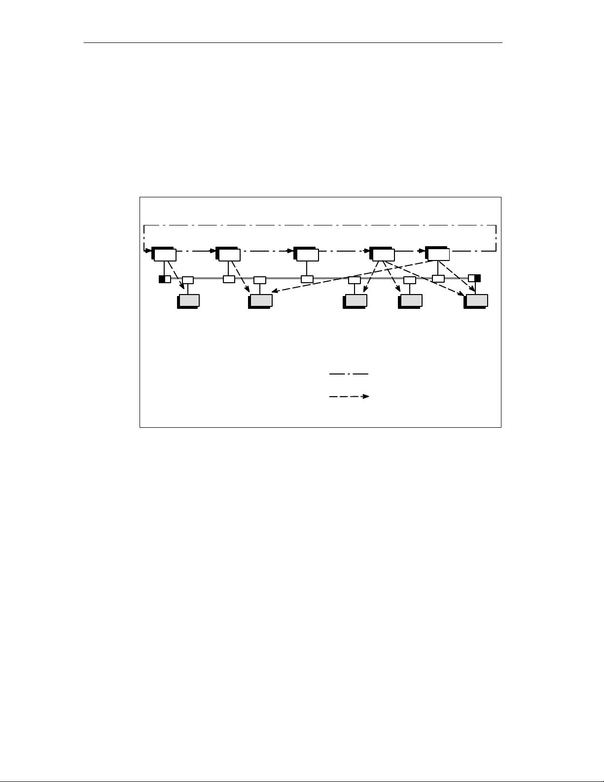
1.2.2 Access Techniques
TOKEN BUS/Master-Slave Method
Network access on PROFIBUS corresponds to the method specified in EN 50170,
Volume 2 “Token Bus” for active and “Master-Slave” for passive stations.
Slave
Master
Token rotation
(logical ring)
Slave = passive node
Logical token ring
Master-slave relationship
Master
Master
Master
Master
Master = active node
Slave
Slave
Slave
Slave
Figure 1-1 Principle of the PROFIBUS Medium Access Technique

PROFIBUS NETWORKS
1-9
PROFIBUS Networks SIMATIC NET
6GK1970-5CA20-0AA1 Release 2 05/2000
Active and Passive Nodes
The access technique is not dependent on the transmission medium. Figure 1-1
“Principle of the PROFIBUS Medium Access Technique” shows the hybrid
technique with active and passive nodes. This is explained briefly below:
S All active nodes (masters) form the logical token ring in a fixed order and each
active node knows the other active nodes and their order in the logical ring (the
order does not depend on the topological arrangement of the active nodes on
the bus).
S The right to access the medium, the “Token”, is passed from active node to
active node in the order of the logical ring.
S If a node has received the token (addressed to it), it can send frames. The time
in which it is allowed to send frames is specified by the token holding time.
Once this has expired, the node is only allowed to send one high priority
message. If the node does not have a message to send, it passes the token
directly to the next node in the logical ring. The token timers from which the
maximum token holding time is calculated are configured for all active nodes.
S If an active node has the token and if it has connections configured to passive
nodes (master-slave connections), the passive nodes are polled (for example
values read out) or data is sent to the slaves (for example setpoints).
S Passive nodes never receive the token.
This access technique allows nodes to enter or leave the ring during operation.
1.2.3 Transmission Techniques
The physical transmission techniques used depend on the SIMATIC NET
PROFIBUS transmission medium:
S RS-485 for electrical networks on shielded, twisted pair cables
S Optical techniques according to the PROFIBUS User Organization guideline /3/
on fiber-optic cables
S Wireless techniques based on infrared radiation
S IEC 61158-2 technique for intrinsically safe and non-intrinsically safe electrical
networks in process control (PROFIBUS-PA) based on shielded, twisted pair
cables.

PROFIBUS NETWORKS
1-10
PROFIBUS Networks SIMATIC NET
6GK1970-5CA20-0AA1 Release 2 05/2000
1.2.4 Transmission Techniques According to EIA Standard RS-485
EIA Standard RS-485
The RS-485 transmission technique corresponds to balanced data transmission as
specified in the EIA Standard RS-485 /4/. This transmission technique is
mandatory in the PROFIBUS standard EN 50170 for data transmission on twisted
pair cables.
The medium is a shielded, twisted pair cable.
The bus cable is terminated at both ends with the characteristic impedance. Such
a terminated bus cable is known as a segment.
The attachment of the node to the bus is via a bus terminal with a tap line or a bus
connector (maximum 32 nodes per segment). The individual segments are
interconnected by repeaters.
The maximum length of a segment depends on the following:
S The transmission rate
S The type of cable being used
Advantages:
S Flexible bus or tree structure with repeaters, bus terminals, and bus connectors
for attaching PROFIBUS nodes
S Purely passive passing on of signals allows nodes to be deactivated without
affecting the network (except for the nodes that supply power to the terminating
resistors)
S Simple installation of the bus cable without specialized experience.

PROFIBUS NETWORKS
1-11
PROFIBUS Networks SIMATIC NET
6GK1970-5CA20-0AA1 Release 2 05/2000
Restrictions:
S Distance covered reduces as the transmission rate increases
S Requires additional lightning protection measures when installed outdoors
Properties of the RS-485 Transmission Technique
The RS-485 transmission technique in PROFIBUS has the following physical
characteristics:
Table 1-1 Physical Characteristics of the RS-485 Transmission Technique
Network topology:
Bus, tree structure with the use of repeaters
Medium: Shielded, twisted pair cable
Possible segment lengths:
(depending on the cable
type, see Table 3.1)
1,000 mFor transmission rates up to 187.5 Kbps
400 m For a transmission rate of 500 Kbps
200 m For a transmission rate of 1.5 Mbps Mbps
100 m For transmission rates of 3.6 and 12 Mbps
Number of repeaters con-
nected in series:
Maximum 9
Number of nodes: Maximum 32 on one bus segment
Maximum 127 per network when using repeaters
Transmission rates: 9.6 Kbps, 19.2 Kbps, 45.45 Kbps, 93.75 Kbps, 187.5 Kbps, 500 Kbps, 1.5
Mbps, 3 Mbps, 6 Mbps, 12 Mbps
Note
The properties listed in 1-1 assume a bus cable of type A and a bus terminator
according to the PROFIBUS standard EN 50170–1–2. The SIMATIC NET
PROFIBUS cables and bus connectors meet this specification. If reductions in the
segment length are necessary when using special versions of the bus cable with
increased d.c. loop resistance, this is pointed out in the sections on
“Configuration” and “SIMATIC NET PROFIBUS Cables”.

PROFIBUS NETWORKS
1-12
PROFIBUS Networks SIMATIC NET
6GK1970-5CA20-0AA1 Release 2 05/2000
1.2.5 Transmission Techniques for Optical Components
PROFIBUS User Organization Guideline
The optical transmission technique complies with the PROFIBUS User
Organization guideline:
“Fiber Optic Data Transfer for PROFIBUS” /3/.
Integrated Optical Interfaces, OBT, OLM
The optical version of SIMATIC NET PROFIBUS is implemented with integrated,
optical ports, optical bus terminals (OBT) and optical link modules (OLM).
Duplex fiber-optic cables are used as the medium made of glass, PCF or plastic
fibers. Duplex fiber-optic cables consist of two conducting fibers surrounded by a
common jacket to form a cable.
Modules with integrated optical ports and optical bus terminals (OBTs) can be
interconnected to form optical networks only with a bus structure.
Using OLMs, optical networks can be installed using a bus, star and ring structure.
The ring structure provides a redundant signal transmission path and represents
the basis for networks with high availability.
Advantages:
S Regardless of the transmission rate, large distances can be covered between
two DTEs
(connections between OLM and OLM up to 15,000 m)
S Electrical isolation between nodes and transmission medium
S When plant components at different ground potential are connected, there are
no shield currents
S No electromagnetic interference
S No additional lightning protection elements are required
S Simple laying of fiber-optic cables
S High availability of the LAN due to the use of a ring topology
S Extremely simple attachment technique using plastic fiber-optic cables over
shorter distances.

PROFIBUS NETWORKS
1-13
PROFIBUS Networks SIMATIC NET
6GK1970-5CA20-0AA1 Release 2 05/2000
Restrictions:
S Frame throughput times are increased compared with an electrical network
S The assembly of glass fiber-optic cables with connectors requires specialist
experience and tools
S The absence of a power supply at the signal coupling points (node attachments,
OLMs, OBTs) stops the signal flow
Characteristics of the Optical Transmission Technique
The optical transmission technique has the following characteristics:
Network topology: Bus structure with integrated optical ports and OBT;
bus, star or ring structure with OLMs
Medium: Fiber-optic cables with glass, PCF or plastic fibers
Link lengths
(point-to-point)
With glass fibers up to 15,000 m dependent on the fiber and OLM
type
with plastic fibers:
OLM: 0 m to 80 m
OBT: 1 m to 50 m
Transmission rate: 9.6 Kbps, 19.2 Kbps, 45.45 Kbps, 93.75 Kbps, 187.5 Kbps, 500
Kbps, 1.5 Mbps, 3 Mbps*, 6 Mbps*, 12 Mbps
Number of nodes: Maximum of 127 per network (126 with ring structure with OLMs)
* not with integrated optical ports and OBT
Note
The optical ports of the OLMs are optimized for greater distances. The direct
coupling of the optical ports of an OLM with an OBT or integrated optical ports is
not possible due to differences in the technical specifications.

PROFIBUS NETWORKS
1-14
PROFIBUS Networks SIMATIC NET
6GK1970-5CA20-0AA1 Release 2 05/2000
1.2.6 Transmission Technique for Wireless Infrared Technology
The wireless PROFIBUS network uses infrared light for signal transmission. The
only transmission medium is a free line-of-sight connection between two nodes.
The maximum distance covered is approximately 15 m. Wireless networks are
implemented using infrared link modules (ILM). The nodes to be networked are
attached to the electrical port of the ILM.
Advantages:
S High mobility of attached plant components (for example trolleys)
S Coupling and decoupling from the fixed network with no wear and tear (for
example substitute for a slip ring)
S Coupling without cable installation (temporary setup, inaccessible areas)
S Not protocol dependent
S Electrical isolation between nodes and hardwired network
Restrictions
S Transmission rate <= 1.5 Mbps
S Free line-of-sight path required between nodes
S Maximum distance covered <= 15 m
S Only for single master networks
Characteristics of the Wireless Infrared Transmission Technique
The wireless infrared transmission technique has the following characteristics:
Network topology: Point-to-point
Point-to-multipoint
Medium: Free space with line-of-sight path
Maximum link length: 15 m
Transmission rate ILM: 9.6 Kbps, 19.2 Kbps, 45.45 Kbps, 93.75 Kbps, 187.5 Kbps,
500 Kbps, 1.5 Mbps
Number of nodes: Maximum 127 per network

PROFIBUS NETWORKS
1-15
PROFIBUS Networks SIMATIC NET
6GK1970-5CA20-0AA1 Release 2 05/2000
1.2.7 Transmission Technique for PROFIBUS-PA
IEC 61158-2 Standard
The transmission technique corresponds to the IEC 61158-2 standard (identical
with EN 61158-2).
The transmission medium is a shielded, twisted pair cable. The signal is
transmitted as a synchronous data stream Manchester-coded at 31.25 Kbps. In
general, the data line is normally also used to supply power to the field devices.
Advantages:
S Simple cabling with twisted pair
S Remote power supply via the signal cores
S Intrinsically safe operation possible (for hazardous areas)
S Bus and tree topology
S Up to 32 nodes per cable segment
Restrictions:
S Transmission rate restricted to 31.25 Kbps
Characteristics of the IEC 61158-2 Transmission Technique
The main characteristics of the IEC 61158-2 transmission technique are as follows:
Network topology: Bus, star and tree topology
Medium:
Shielded, twisted pair cable
Achievable segment lengths: 1900 m
Transmission rate:
31.25 Kbps
Number of nodes: Maximum 127 per network

PROFIBUS NETWORKS
1-16
PROFIBUS Networks SIMATIC NET
6GK1970-5CA20-0AA1 Release 2 05/2000

2-1
PROFIBUS Networks SIMATIC NET
6GK1970-5CA20-0AA1 Release 2 05/2000
Topologies of SIMATIC NET PROFIBUS
Networks
2

Topologies of SIMATIC NET PROFIBUS Networks
2-2
PROFIBUS Networks SIMATIC NET
6GK1970-5CA20-0AA1 Release 2 05/2000
2.1 Topologies of RS-485 Networks
Transmission Rate
When operating SIMATIC NET PROFIBUS in the RS-485 transmission technique,
the user can select one of the transmission rates below:
9.6 Kbps, 19.2 Kbps, 45.45 Kbps, 93.75 Kbps, 187.5 Kbps, 500 Kbps,
1.5 Mbps, 3 Mbps, 6 Mbps or 12 Mbps
Depending on the transmission rate, transmission medium, and network
components different segment lengths and therefore different network spans can
be implemented.
The bus attachment components can be divided into two groups:
S Components for transmission rates from 9.6 Kbps to a maximum of 1.5 Mbps
S Components for transmission rates from 9.6 Kbps to a maximum of 12 Mbps
LAN Cable
The transmission media used are the SIMATIC NET PROFIBUS cables described
in Chapter 4. The technical information below applies only to networks
implemented with these cables and SIMATIC NET PROFIBUS components.
Node Attachment
The nodes are attached to the LAN cables via bus connectors, bus terminals or
RS-485 repeaters.
Cable Termination
Each bus segment must be terminated at both ends with its characteristic
impedance. This cable terminator is integrated in the RS-485 repeaters, the bus
terminals, the ILM and the bus connectors and can be activated if required.
Before the cable terminator can be activated, the component must be supplied with
power. With the bus terminals and the bus connectors, this power is supplied by
the connected DTE, whereas the RS-485 repeater, the ILM, and the terminator
have their own power supply.
The RS-485 transmission technique allows the attachment of a maximum of 32
devices (DTEs and repeaters) per bus segment. The maximum permitted cable
length of a segment depends on the transmission rate and the LAN cable used.
Topologies of SIMATIC NET PROFIBUS Networks
2-3
PROFIBUS Networks SIMATIC NET
6GK1970-5CA20-0AA1 Release 2 05/2000
Connecting Segments Using RS-485 Repeaters
By using RS-485 repeaters, segments can be interconnected. The RS-485
repeater amplifies the data signals on the LAN cables. You require an RS-485
repeater when you want to attach more than 32 nodes to a network or when the
permitted segment length is exceeded. A maximum of 9 repeaters can be used
between any two nodes. Both bus and tree structures can be implemented.
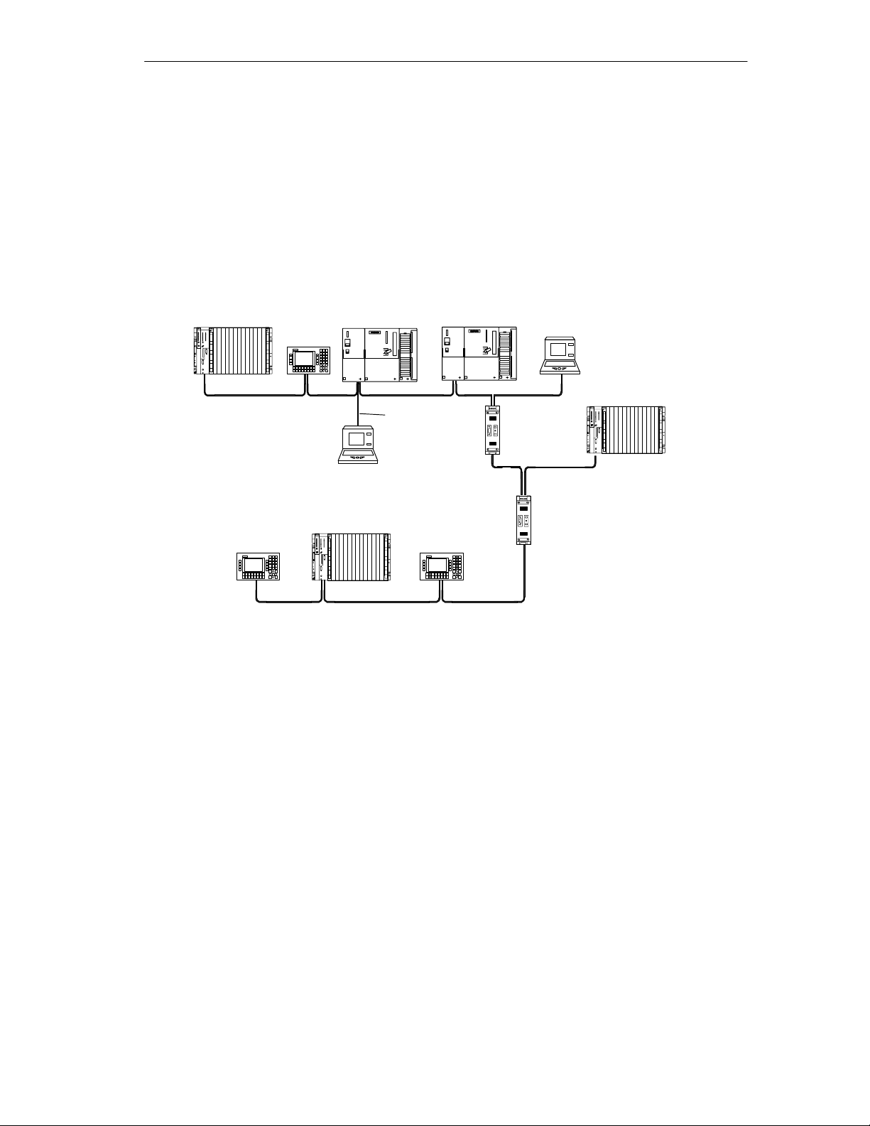
Figure 2-1 shows a typical topology using the RS-485 technique with 3 segments
and 2 repeaters.
Terminating resistor activated
PG attached via tap line (6ES7 901-4BD00-0XA0)
for maintenance purposes
RS-485
repeater
RS-485
repeater
S7-400
S7-300 S7-300
S7-400
S7-400
Tap line
OP 25
PG
OP 25
OP 25
PG
Figure 2-1 Topology Using the RS-485 Technique
Increasing the overall span of a network by using repeaters can lead to longer
transmission times that may need to be taken into account when configuring the
network (see Chapter 3).
2.1.1 Components for Transmission Rates up to 1.5 Mbps
All SIMATIC NET bus attachment components can be used for transmission rates
≤ 1.5 Mbps.

Topologies of SIMATIC NET PROFIBUS Networks
2-4
PROFIBUS Networks SIMATIC NET
6GK1970-5CA20-0AA1 Release 2 05/2000
2.1.2 Components for Transmission Rates up to
12 Mbps
The following bus attachment components can be used for transmission rates up
to 12 Mbps:
Table 2-1 Bus Attachment Components for Transmission Rates up to 12 Mbps
Order number
PROFIBUS bus connector with
axial cable outlet
6GK1 500-0EA02
PROFIBUS FastConnect bus connector RS-485
Plug 180
with 180° cable outlet 6GK1500-0FC00
RS-485 bus connector with vertical cable outlet
Without PG interface
With PG interface
6ES7 972-0BA11-0XA0
6ES7 972-0BB11-0XA0
PROFIBUS FastConnect RS-485 bus connector
with 90° cable outlet with insulation displacement terminal
system
max. transmission rate 12 Mbps
Without PG interface
With PG interface
6ES7 972-0BA50-0XA0
6ES7 972-0BB50-0XA0
RS-485 bus connector with 35
o
cable outlet
Without PG interface
With PG interface
6ES7 972-0BA40-0XA0
6ES7 972-0BB40-0XA0
SIMATIC NET 830-1T connecting cable, preassembled, fitted
with terminating resistors, as link between electrical interface
of an OLM or OBT and the PROFIBUS interface of a
PROFIBUS node.
1.5 m
3 m
6XV1830-1CH15
6XV1830-1CH30
SIMATIC NET 830-2 connecting cable for PROFIBUS,
preassembled cable with two sub-D, 9-pin male connectors,
terminating resistors can be activated.
3 m
5 m
10 m
6XV1830-2AH30
6XV1830-2AH50
6XV1830-2AN10
SIMATIC S5/S7 PROFIBUS connecting cable
for connecting programming devices up to 12 Mbps
preassembled with 2 sub-D connectors, length 3 m 6ES7 901-4BD00-0XA0
PROFIBUS RS-485 repeater 24 V DC, casing with IP 20
degree of protection
6ES7 972-0AA01-0XA0
Bus terminal BT12M 6GK1 500-0AA10
Optical Link Module OLM V3 6GK1 502-_C_00
Loading...