


 Loading...
SIMATIC
Automation System S7-400
Hardware and Installation
Installation Manual
This manual is part of the documentation package with the order number
6ES7498-8AA05-8BA0
11/2006
Preface, Contents
Product Overview
Installing the S7-400
Addressing the S7-400
Wiring the S7-400
Networking
Commissioning
Maintenance
Appendices
Assembling and
Installing Systems
Guidelines for Handling Electro- statically-Sensitive Devices (ESD)
Glossary, Index
1
2
3
4
5
6
7
A B
A5E00850741-01

Safety Guidelines
This manual contains notices you have to observe in order to ensure your personal safety, as well as to prevent damage to property. The notices referring to your personal safety are highlighted in the manual by a safety alert symbol, notices referring to property damage only have no safety alert symbol. The notices shown below are graded according to the degree of danger.
Danger
!indicates that death or severe personal injury will result if proper precautions are not taken.
Warning
!indicates that death or severe personal injury may result if proper precautions are not taken.
Caution
!with a safety alert symbol indicates that minor personal injury can result if proper precautions are not taken.
Caution
without a safety alert symbol indicates that property damage can result if proper precautions are not taken.
Notice
indicates that an unintended result or situation can occur if the corresponding notice is not taken into account.
If more than one degree of danger is present, the warning notice representing the highest degree of danger will be used. A notice warning of injury to persons with a safety alert symbol may also include a warning relating to property damage.
Qualified Personnel
The device/system may only be set up and used in conjunction with this documentation. Commissioning and operation of a device/system may only be performed by qualified personnel. Within the context of the safety notices in this documentation qualified persons are defined as persons who are authorized to commission, ground and label devices, systems and circuits in accordance with established safety practices and standards.
Prescribed Usage
Note the following:
Warning
!This device and its components may only be used for the applications described in the catalog or the technical description, and only in connection with devices or components from other manufacturers which have been approved or recommended by Siemens.
Correct, reliable operation of the product requires proper transport, storage, positioning and assembly as well as careful operation and maintenance.
Trademarks
All names identified by → are registered trademarks of the Siemens AG.
The remaining trademarks in this publication may be trademarks whose use by third parties for their own purposes could violate the rights of the owner.
Disclaim of Liability
We have reviewed the contents of this publication to ensure consistency with the hardware and software described. Since variance cannot be precluded entirely, we cannot guarantee full consistency. However, the information in this publication is reviewed regularly and any necessary corrections are included in subsequent editions.
SIEMENS AG |
A5E00850741-01 |
Copyright E Siemens AG 2006 |
Automation and Drives |
11/2006 |
Technical data subject to change |
Postfach 4848
90437 NÜRNBERG GERMANY

Preface
Purpose of the Manual
The manual contains reference information on operator actions, descriptions of functions and technical specifications of the central processing units, power supply modules and interface modules of the S7-400.
How to configure, assemble and wire these modules (and other) in an S7-400 system is described in the installation manuals for each system.
Required Basic Knowledge
You will need general knowledge of automation to understand this manual.
Prerequisite is also sufficient knowledge in the use of computers or PC-type equipment (programming devices, for example) with Windows 2000 or XP operating system. The S7-400 system is configured in STEP 7 standard software. You should therefore have sufficient knowledge of this standard software. This knowledge is provided in the “Programming with STEP 7” manual.
Please note the information on the safety of electronic control systems in the appendix of this manual, in particular when operating an S7-400 in safety-relevant areas.
Scope of this Manual
The manual applies to the S7-400 automation system.
Approvals
You can find details on approvals and standards in the “Module Data” reference manual.
Place of this Documentation in the Information Environment
This manual is part of the documentation package for S7-400.
System |
|
|
Documentation Package |
|
|
|
|
S7-400 |
• |
S7-400 |
Programmable Controller; Hardware and Installation |
|
• |
S7-400 |
Programmable Controllers; Module Data |
|
• Automation System S7-400; CPU Data |
||
|
• |
S7-400 |
Instruction List |
|
|
|
|
Automation System S7-400 |
Hardware and Installation |
iii |
A5E00850741-01 |
|

Preface
Navigating
The manual offers the following access help to make it easy for you to find specific information:
•At the start of the manual you will find a complete table of contents and a list of the diagrams and tables that appear in the manual.
•An overview of the contents of each section is provided in the left column on each page of each chapter.
•You will find a glossary in the appendix at the end of the manual. The glossary contains definitions of the main technical terms used in the manual.
•At the end of the manual you will find a comprehensive index which gives you rapid access to the information you need.
Recycling and Disposal
The S7-400 is low in contaminants and can therefore be recycled. To recycle and dispose of your old device in an environment-friendly manner, please contact a disposal company certified for disposal of electronic waste.
Further Support
If you have any technical questions, please get in touch with your Siemens representative or responsible agent .
You will find your contact person at:
http://www.siemens.com/automation/partner
You will find a guide to the technical documentation offered for the individual SIMATIC Products and Systems here at:
http://www.siemens.com/simatic-tech-doku-portal
The online catalog and order system is found under:
http://mall.automation.siemens.com
Training Centers
Siemens offers a number of training courses to familiarize you with the SIMATIC S7 automation system. Please contact your regional training center or our central training center in D 90327 Nuremberg, Germany for details:
Telephone: |
+49 (911) 895-3200. |
Internet: |
http://www.sitrain.com |
iv |
Automation System S7-400 |
Hardware and Installation |
|
A5E00850741-01 |

Preface
Technical Support
You can reach the Technical Suport for all A&D products
•Via the Web formula for the Support Request http://www.siemens.com/automation/support-request
•Phone: + 49 180 5050 222
•Fax:+ 49 180 5050 223
Additional information about our Technical Support can be found on the Internet pages:
http://www.siemens.com/automation/service.
Service & Support on the Internet
In addition to our documentation, we offer our Know-how online on the internet at:
http://www.siemens.com/automation/service&support
where you will find the following:
•The newsletter, which constantly provides you with up-to-date information on your products.
•The right documents via our Search function in Service & Support.
•A forum, where users and experts from all over the world exchange their experiences.
•Your local representative for Automation & Drives.
•Information on field service, repairs, spare parts and more under “Services”.
Automation System S7-400 |
Hardware and Installation |
v |
A5E00850741-01 |
|

Preface
vi |
Automation System S7-400 |
Hardware and Installation |
|
A5E00850741-01 |
|
|
|
|

Contents
1 |
Product Overview . . . . . . . . . . . . . . . . . . . . . . . . . . . . . . . . . . . . . . . . . . . . . . . . . . . . . . |
1-1 |
|
2 |
Installing the S7-400 . . . . . . . . . . . . . . . . . . . . . . . . . . . . . . . . . . . . . . . . . . . . . . . . . . . . |
2-1 |
|
|
2.1 |
S7-400 Installation . . . . . . . . . . . . . . . . . . . . . . . . . . . . . . . . . . . . . . . . . . . . . . |
2-2 |
|
2.2 |
Installing the Central Rack (CR) and Expansion Rack (ER) . . . . . . . . . . . . |
2-6 |
|
2.3 |
Segmented CR . . . . . . . . . . . . . . . . . . . . . . . . . . . . . . . . . . . . . . . . . . . . . . . . . |
2-8 |
|
2.4 |
Subdivided CR . . . . . . . . . . . . . . . . . . . . . . . . . . . . . . . . . . . . . . . . . . . . . . . . . . |
2-9 |
|
2.5 |
Mounting and Grounding the Racks . . . . . . . . . . . . . . . . . . . . . . . . . . . . . . . . |
2-10 |
|
2.6 |
Chassis Terminal Connection in the Non-Isolated Configuration . . . . . . . . |
2-16 |
|
2.7 |
Methods of Ventilation . . . . . . . . . . . . . . . . . . . . . . . . . . . . . . . . . . . . . . . . . . . |
2-18 |
2.8Changing the Ventilation with the Cable Duct and Fan Subassembly . . . 2-20
|
2.9 |
Installing the Fan Subassembly . . . . . . . . . . . . . . . . . . . . . . . . . . . . . . . . . . . |
2-22 |
|
2.10 |
Installing the Cable Duct . . . . . . . . . . . . . . . . . . . . . . . . . . . . . . . . . . . . . . . . . |
2-24 |
|
2.11 |
Choosing and Setting up Cabinets with the S7-400 . . . . . . . . . . . . . . . . . . |
2-25 |
|
2.12 |
Rules for the Arrangement of Modules . . . . . . . . . . . . . . . . . . . . . . . . . . . . . |
2-29 |
|
2.13 |
Installing Modules in a Rack . . . . . . . . . . . . . . . . . . . . . . . . . . . . . . . . . . . . . . |
2-30 |
|
2.14 |
Marking the Modules with Slot Labels . . . . . . . . . . . . . . . . . . . . . . . . . . . . . . |
2-33 |
|
2.15 |
Methods of Expansion and Networking . . . . . . . . . . . . . . . . . . . . . . . . . . . . . |
2-34 |
|
2.16 |
Accessories . . . . . . . . . . . . . . . . . . . . . . . . . . . . . . . . . . . . . . . . . . . . . . . . . . . . |
2-35 |
3 |
Addressing the S7-400 . . . . . . . . . . . . . . . . . . . . . . . . . . . . . . . . . . . . . . . . . . . . . . . . . . |
3-1 |
|
|
3.1 |
Geographical and Logical Addresses . . . . . . . . . . . . . . . . . . . . . . . . . . . . . . |
3-2 |
|
3.2 |
How to Determine the Default Address of a Module . . . . . . . . . . . . . . . . . . |
3-4 |
|
3.3 |
How to Determine the Default Address of a Channel . . . . . . . . . . . . . . . . . |
3-6 |
4 |
Wiring the S7-400 . . . . . . . . . . . . . . . . . . . . . . . . . . . . . . . . . . . . . . . . . . . . . . . . . . . . . . . |
4-1 |
|
|
4.1 |
Supplying Power to Modules . . . . . . . . . . . . . . . . . . . . . . . . . . . . . . . . . . . . . . |
4-2 |
|
4.2 |
Choosing the Power Supply Module . . . . . . . . . . . . . . . . . . . . . . . . . . . . . . . |
4-3 |
|
4.3 |
Choosing the Load Current Power Supply . . . . . . . . . . . . . . . . . . . . . . . . . . |
4-4 |
|
4.4 |
Assembling an S7-400 with Process I/Os . . . . . . . . . . . . . . . . . . . . . . . . . . . |
4-5 |
|
4.5 |
Assembling an S7-400 with Grounded Reference Potential (M) . . . . . . . . |
4-7 |
4.6Assembling an S7-400 with Ungrounded Reference Potential
|
(Ungrounded Configuration) . . . . . . . . . . . . . . . . . . . . . . . . . . . . . . . . . . . . . . |
4-8 |
4.7 |
Assembling an S7-400 with Isolated Modules . . . . . . . . . . . . . . . . . . . . . . . |
4-10 |
4.8 |
Parallel Wiring of Digital S7-400 Outputs . . . . . . . . . . . . . . . . . . . . . . . . . . . |
4-12 |
Automation System S7-400 Hardware and Installation |
vii |
|
A5E00850741-01 |
|
|

Contents
4.9 Grounding . . . . . . . . . . . . . . . . . . . . . . . . . . . . . . . . . . . . . . . . . . . . . . . . . . . . . . 4-13
4.10Interference-Free Configuration for Local and Remote Connections . . . . 4-15
4.11 Wiring Rules . . . . . . . . . . . . . . . . . . . . . . . . . . . . . . . . . . . . . . . . . . . . . . . . . . . . 4-17 4.12 Wiring the Power Supply Module . . . . . . . . . . . . . . . . . . . . . . . . . . . . . . . . . . 4-18 4.13 Wiring the Signal Modules . . . . . . . . . . . . . . . . . . . . . . . . . . . . . . . . . . . . . . . . 4-22 4.14 Wiring the Front Connector, Crimping . . . . . . . . . . . . . . . . . . . . . . . . . . . . . . 4-24 4.15 Wiring the Front Connector, Screw Terminals . . . . . . . . . . . . . . . . . . . . . . . 4-25 4.16 Wiring the Front Connector, Spring-Type Terminals . . . . . . . . . . . . . . . . . . 4-26 4.17 Fitting the Strain Relief . . . . . . . . . . . . . . . . . . . . . . . . . . . . . . . . . . . . . . . . . . . 4-28 4.18 Labeling a Front Connector . . . . . . . . . . . . . . . . . . . . . . . . . . . . . . . . . . . . . . . 4-29 4.19 Fitting the Front Connector . . . . . . . . . . . . . . . . . . . . . . . . . . . . . . . . . . . . . . . 4-32 4.20 Interconnecting the CR and ER(s) . . . . . . . . . . . . . . . . . . . . . . . . . . . . . . . . . 4-35 4.21 Setting the Fan Subassembly to the Line Voltage and Wiring It . . . . . . . . 4-37 4.22 Cable routing in cable ducts or fan subassemblies . . . . . . . . . . . . . . . . . . . 4-38 4.23 Routing Fiber-Optic Cables . . . . . . . . . . . . . . . . . . . . . . . . . . . . . . . . . . . . . . . 4-38
5 |
Networking . . . . . . . . . . . . . . . . . . . . . . . . . . . . . . . . . . . . . . . . . . . . . . . . . . . . . . . . . . . . . |
5-1 |
|
|
5.1 |
Configuring a Network . . . . . . . . . . . . . . . . . . . . . . . . . . . . . . . . . . . . . . . . . . . |
5-2 |
|
5.2 |
Fundamentals . . . . . . . . . . . . . . . . . . . . . . . . . . . . . . . . . . . . . . . . . . . . . . . . . . |
5-3 |
|
5.3 |
Rules for Configuring a Network . . . . . . . . . . . . . . . . . . . . . . . . . . . . . . . . . . . |
5-7 |
|
5.4 |
Cable Lengths . . . . . . . . . . . . . . . . . . . . . . . . . . . . . . . . . . . . . . . . . . . . . . . . . . |
5-15 |
|
5.5 |
PROFIBUS-DP Bus Cables . . . . . . . . . . . . . . . . . . . . . . . . . . . . . . . . . . . . . . . |
5-18 |
|
5.6 |
Bus Connectors . . . . . . . . . . . . . . . . . . . . . . . . . . . . . . . . . . . . . . . . . . . . . . . . . |
5-19 |
|
5.7 |
RS 485 Repeater / Diagnostics Repeater . . . . . . . . . . . . . . . . . . . . . . . . . . . |
5-21 |
|
5.8 |
PROFIBUS-DP Network with Fiber-Optic Cables . . . . . . . . . . . . . . . . . . . . |
5-22 |
|
5.8.1 |
Fiber-Optic Cables . . . . . . . . . . . . . . . . . . . . . . . . . . . . . . . . . . . . . . . . . . . . . . |
5-24 |
|
5.8.2 |
Simplex Connectors and Connector Adapter . . . . . . . . . . . . . . . . . . . . . . . . |
5-26 |
|
5.8.3 |
Connecting a Fiber-Optic Cable to the PROFIBUS Device . . . . . . . . . . . . |
5-28 |
6 |
Commissioning . . . . . . . . . . . . . . . . . . . . . . . . . . . . . . . . . . . . . . . . . . . . . . . . . . |
. . . . . . 6-1 |
|
|
6.1 |
Recommended Procedure for First Startup . . . . . . . . . . . . . . . . . . . |
. . . . . . 6-2 |
|
6.2 |
Checks Prior to Switching On for the First Time . . . . . . . . . . . . . . . . |
. . . . . . 6-3 |
|
6.3 |
Connecting a Programming Device (PG) to an S7-400 . . . . . . . . . |
. . . . . . 6-5 |
|
6.4 |
Switching On an S7-400 for the First Time . . . . . . . . . . . . . . . . . . . . |
. . . . . . 6-6 |
|
6.5 |
Resetting the CPU with the Mode Selector Switch . . . . . . . . . . . . . |
. . . . . . 6-7 |
|
6.6 |
Cold, Warm, and Hot Restarts with the Mode Selector Switch . . . |
. . . . . . 6-10 |
|
6.7 |
Inserting a Memory Card . . . . . . . . . . . . . . . . . . . . . . . . . . . . . . . . . . . |
. . . . . . 6-11 |
|
6.8 |
Inserting a Backup Battery (Option) . . . . . . . . . . . . . . . . . . . . . . . . . . |
. . . . . . 6-13 |
|
6.9 |
Starting Up a PROFIBUS-DP Subnet . . . . . . . . . . . . . . . . . . . . . . . . |
. . . . . . 6-17 |
|
6.10 |
Installing Interface Modules (CPU 414-2, 414-3, 416-3, 417-4 |
|
|
|
and 417-4H) . . . . . . . . . . . . . . . . . . . . . . . . . . . . . . . . . . . . . . . . . . . . . . |
. . . . . . 6-18 |
viii |
|
Automation System S7-400 Hardware and Installation |
|
|
|
A5E00850741-01 |
|

|
|
|
Contents |
|
|
|
|
7 |
Maintenance . . . . . . . . . . . . . . . . . . . . . . . . . . . . . . . . . . . . . . . . . . . . . . . . . . . . . . . . . |
. . 7-1 |
|
|
7.1 |
Replacing the Backup Battery . . . . . . . . . . . . . . . . . . . . . . . . . . . . . . . . . . . . |
. 7-2 |
|
7.2 |
Replacing a Power Supply Module . . . . . . . . . . . . . . . . . . . . . . . . . . . . . . . . |
. 7-4 |
|
7.3 |
Replacing CPUs . . . . . . . . . . . . . . . . . . . . . . . . . . . . . . . . . . . . . . . . . . . . . . . |
. 7-5 |
|
7.4 |
Replacing Digital or Analog Modules . . . . . . . . . . . . . . . . . . . . . . . . . . . . . . |
. 7-7 |
|
7.5 |
Changing the Fuses in the Digital Modules . . . . . . . . . . . . . . . . . . . . . . . . . |
. 7-9 |
|
7.6 |
Replacing Interface Modules . . . . . . . . . . . . . . . . . . . . . . . . . . . . . . . . . . . . . |
. 7-11 |
|
7.7 |
Replacing the Fuse of the Fan Subassembly . . . . . . . . . . . . . . . . . . . . . . . |
. 7-13 |
|
7.8 |
Replacing Fans in the Fan Subassembly During Operation . . . . . . . . . . . |
. 7-14 |
|
7.9 |
Replacing the Filter Frame of the Fan Subassembly During Operation . |
. 7-16 |
7.10Replacing the Power Supply PCB and Monitoring PCB
|
|
of the Fan Subassembly . . . . . . . . . . . . . . . . . . . . . . . . . . . . . . . . . . . . . . . . . . |
7-18 |
|
7.11 |
Replacing Interface Submodules . . . . . . . . . . . . . . . . . . . . . . . . . . . . . . . . . . |
7-19 |
A |
Assembling and Installing Systems . . . . . . . . . . . . . . . . . . . . . . . . . . . . . . . . . . . . . . |
A-1 |
|
|
A.1 |
General Rules and Regulations for Operating the S7-400 . . . . . . . . . . . . . |
A-2 |
|
A.2 |
Principles of System Installation for EMC . . . . . . . . . . . . . . . . . . . . . . . . . . . |
A-5 |
|
A.3 |
Installation of Programmable Controllers for EMC . . . . . . . . . . . . . . . . . . . . |
A-9 |
|
A.4 |
Examples of EMC-Compatible Assembly . . . . . . . . . . . . . . . . . . . . . . . . . . . |
A-10 |
|
A.5 |
Shielding Cables . . . . . . . . . . . . . . . . . . . . . . . . . . . . . . . . . . . . . . . . . . . . . . . . |
A-13 |
|
A.6 |
Equipotential Bonding . . . . . . . . . . . . . . . . . . . . . . . . . . . . . . . . . . . . . . . . . . . . |
A-15 |
|
A.7 |
Cabling Inside Buildings . . . . . . . . . . . . . . . . . . . . . . . . . . . . . . . . . . . . . . . . . . |
A-17 |
|
A.8 |
Cabling Outside Buildings . . . . . . . . . . . . . . . . . . . . . . . . . . . . . . . . . . . . . . . . |
A-19 |
|
A.9 |
Lightning Protection and Overvoltage Protection . . . . . . . . . . . . . . . . . . . . . |
A-20 |
|
A.9.1 |
Lightning Protection Zone Concept . . . . . . . . . . . . . . . . . . . . . . . . . . . . . . . . |
A-21 |
|
A.9.2 |
Rules for the Transition between Lightning Protection Zones 0 and 1 . . . |
A-23 |
|
A.9.3 |
Rules for the Transitions between Lightning Protection Zones 1 <-> 2 |
|
|
|
and Greater . . . . . . . . . . . . . . . . . . . . . . . . . . . . . . . . . . . . . . . . . . . . . . . . . . . . |
A-25 |
|
A.9.4 |
Sample of a Surge Protection Circuit for Networked S7-400 PLCs . . . . . |
A-28 |
|
A.10 |
How to Protect Digital Output Modules against Inductive Surge . . . . . . . . |
A-30 |
|
A.11 |
Safety of Electronic Control Equipment . . . . . . . . . . . . . . . . . . . . . . . . . . . . . |
A-32 |
|
A.12 |
Interference-Free Connection of Monitors . . . . . . . . . . . . . . . . . . . . . . . . . . . |
A-34 |
B |
Guidelines for Handling Electrostatically-Sensitive Devices (ESD) . . . . . . . . . . |
B-1 |
|
|
B.1 |
What is ESD? . . . . . . . . . . . . . . . . . . . . . . . . . . . . . . . . . . . . . . . . . . . . . . . . . . . |
B-2 |
|
B.2 |
Electrostatic Charging of Persons . . . . . . . . . . . . . . . . . . . . . . . . . . . . . . . . . |
B-3 |
|
B.3 |
General Protective Measures Against Electrostatic Discharge Damage . |
B-4 |
Glossary
Index
Automation System S7-400 |
Hardware and Installation |
ix |
A5E00850741-01 |
|

Contents
Figures |
|
|
2-1 |
Rack Fitted with Modules in the S7-400 System . . . . . . . . . . . . . . . . . . . . . |
2-2 |
2-2 |
Max. Cabinet Ambient Temperature as a Function of Power Dissipation |
|
|
of Equipment in the Cabinet . . . . . . . . . . . . . . . . . . . . . . . . . . . . . . . . . . . . . . |
2-27 |
2-3 |
Removing the Cover . . . . . . . . . . . . . . . . . . . . . . . . . . . . . . . . . . . . . . . . . . . . . |
2-31 |
2-4 |
Attaching the Modules . . . . . . . . . . . . . . . . . . . . . . . . . . . . . . . . . . . . . . . . . . . |
2-32 |
2-5 |
Screwing the Modules in Place . . . . . . . . . . . . . . . . . . . . . . . . . . . . . . . . . . . . |
2-32 |
2-6 |
Fitting a Slot Label . . . . . . . . . . . . . . . . . . . . . . . . . . . . . . . . . . . . . . . . . . . . . . . |
2-33 |
4-1 |
Operating the S7-400 from a Grounded Supply . . . . . . . . . . . . . . . . . . . . . . |
4-6 |
4-2 |
An S7-400 Configured with Grounded Reference Potential . . . . . . . . . . . . |
4-7 |
4-3 |
An S7-400 Configured with Ungrounded Reference Potential . . . . . . . . . . |
4-8 |
4-4 |
Simplified Representation of Configuration with Isolated Modules . . . . . . |
4-11 |
4-5 |
Parallel Wiring of a Digital Output with Different Rated Load Voltages . . . |
4-12 |
4-6 |
Parallel Wiring of a Digital Output with Identical Rated Load Voltages . . . |
4-12 |
4-7 |
Grounded connection load voltage . . . . . . . . . . . . . . . . . . . . . . . . . . . . . . . . . |
4-14 |
4-8 |
Shielding and Grounding the Connecting Cable for a Remote Connection |
4-16 |
4-9 |
Disconnecting power supply connector . . . . . . . . . . . . . . . . . . . . . . . . . . . . . |
4-18 |
4-10 |
Wiring the power supply connector . . . . . . . . . . . . . . . . . . . . . . . . . . . . . . . . |
4-20 |
4-11 |
Plugging the power supply connector . . . . . . . . . . . . . . . . . . . . . . . . . . . . . . |
4-21 |
4-12 |
Preparing to wire the front connector . . . . . . . . . . . . . . . . . . . . . . . . . . . . . . . |
4-23 |
4-13 |
Wiring a Front Connector with Crimp Terminals . . . . . . . . . . . . . . . . . . . . . . |
4-24 |
4-14 |
Wiring a Front Connector with Screw-Type Terminals . . . . . . . . . . . . . . . . . |
4-25 |
4-15 |
Wiring a Front Connector with Spring-Type Terminals . . . . . . . . . . . . . . . . |
4-26 |
4-16 |
Principle of the spring contact . . . . . . . . . . . . . . . . . . . . . . . . . . . . . . . . . . . . . |
4-27 |
4-17 |
Fitting a Strain Relief (Viewed from Below) . . . . . . . . . . . . . . . . . . . . . . . . . . |
4-28 |
4-18 |
Fitting the Labels on the Front Connector . . . . . . . . . . . . . . . . . . . . . . . . . . . |
4-29 |
4-19 |
Fitting a Label in the Front Connector . . . . . . . . . . . . . . . . . . . . . . . . . . . . . . |
4-30 |
4-20 |
Attaching the Front Connector . . . . . . . . . . . . . . . . . . . . . . . . . . . . . . . . . . . . |
4-33 |
4-21 |
Screwing On the Front Connector . . . . . . . . . . . . . . . . . . . . . . . . . . . . . . . . . |
4-34 |
4-22 |
Plugging a Connecting Cable into a Send IM . . . . . . . . . . . . . . . . . . . . . . . . |
4-35 |
4-23 |
Connection Between a Send IM and Two Receive IMs . . . . . . . . . . . . . . . |
4-36 |
4-24 |
Wiring the Fan Subassembly . . . . . . . . . . . . . . . . . . . . . . . . . . . . . . . . . . . . . . |
4-37 |
5-1 |
Communication between Programming Device/Operator Panel |
|
|
and a Module without MPI . . . . . . . . . . . . . . . . . . . . . . . . . . . . . . . . . . . . . . . . |
5-5 |
5-2 |
Data Exchange . . . . . . . . . . . . . . . . . . . . . . . . . . . . . . . . . . . . . . . . . . . . . . . . . |
5-6 |
5-3 |
Terminating resistor on bus connector . . . . . . . . . . . . . . . . . . . . . . . . . . . . . . |
5-9 |
5-4 |
Terminating resistor on RS 485 repeater . . . . . . . . . . . . . . . . . . . . . . . . . . . . |
5-9 |
5-5 |
Terminating resistor on MPI network . . . . . . . . . . . . . . . . . . . . . . . . . . . . . . . |
5-10 |
5-6 |
Example of an MPI network . . . . . . . . . . . . . . . . . . . . . . . . . . . . . . . . . . . . . . . |
5-11 |
5-7 |
Example of a PROFIBUS DP network . . . . . . . . . . . . . . . . . . . . . . . . . . . . . . |
5-12 |
5-8 |
Example with CPU 414-2 . . . . . . . . . . . . . . . . . . . . . . . . . . . . . . . . . . . . . . . . . |
5-13 |
5-9 |
Programming device access beyond network limits . . . . . . . . . . . . . . . . . . |
5-14 |
5-10 |
Configuration of an MPI network . . . . . . . . . . . . . . . . . . . . . . . . . . . . . . . . . . . |
5-17 |
5-11 |
Bus connector . . . . . . . . . . . . . . . . . . . . . . . . . . . . . . . . . . . . . . . . . . . . . . . . . . |
5-19 |
5-12 |
Switch on terminating resistant . . . . . . . . . . . . . . . . . . . . . . . . . . . . . . . . . . . . |
5-20 |
5-13 |
Optical PROFIBUS-DP Network with Nodes that have an |
|
|
Integrated Fiber-Optic Cable Interface . . . . . . . . . . . . . . . . . . . . . . . . . . . . . . |
5-23 |
5-14 |
Simplex Connectors and a Special Connector Adapter for the IM 153-2 FO |
|
|
and IM 467 FO (installed) . . . . . . . . . . . . . . . . . . . . . . . . . . . . . . . . . . . . . . . . . |
5-27 |
6-1 |
Connecting PG to an S7-400 . . . . . . . . . . . . . . . . . . . . . . . . . . . . . . . . . . . . . . |
6-5 |
6-2 |
Positions of the mode selector switch . . . . . . . . . . . . . . . . . . . . . . . . . . . . . . |
6-8 |
6-3 |
Inserting a Memory Card in a CPU . . . . . . . . . . . . . . . . . . . . . . . . . . . . . . . . . |
6-12 |
6-4 |
Inserting Interface Submodules in the CPU . . . . . . . . . . . . . . . . . . . . . . . . . |
6-19 |
7-1 |
Inserting an Interface Submodule in a CPU . . . . . . . . . . . . . . . . . . . . . . . . . |
7-20 |
x |
Automation System S7-400 Hardware and Installation |
|
A5E00850741-01 |
||
|
|
Contents |
|
|
|
A-1 |
The Possible Routes for Electromagnetic Interference . . . . . . . . . . . . . . |
. . A-5 |
A-2 |
Example of Cabinet Installation for EMC . . . . . . . . . . . . . . . . . . . . . . . . . . |
. . A-10 |
A-3 |
Wall Mounting an S7-400 for EMC . . . . . . . . . . . . . . . . . . . . . . . . . . . . . . . |
. . A-12 |
A-4 |
Mounting Cable Shields . . . . . . . . . . . . . . . . . . . . . . . . . . . . . . . . . . . . . . . . |
. . A-14 |
A-5 |
Routing Equipotential Bonding Conductor and Signal Line . . . . . . . . . . . |
. A-16 |
A-6 |
Lightning Protection Zones of a Building . . . . . . . . . . . . . . . . . . . . . . . . . . . |
. A-22 |
A-7 |
Sample Circuitry for Networked S7-400 PLCs . . . . . . . . . . . . . . . . . . . . . . |
. A-28 |
A-8 |
Relay Contact for EMERGENCY OFF in the Output Circuit . . . . . . . . . . . |
. A-30 |
A-9 |
Suppression for DC-Operated Coils . . . . . . . . . . . . . . . . . . . . . . . . . . . . . . . |
. A-31 |
A-10 |
Suppression with AC-Operated Coils . . . . . . . . . . . . . . . . . . . . . . . . . . . . . . |
. A-31 |
A-11 |
Shielding and Grounding with a Great Distance between Monitor |
|
|
and Programmable Controller . . . . . . . . . . . . . . . . . . . . . . . . . . . . . . . . . . . . |
. A-36 |
B-1 |
Electrostatic Voltages which can build up on a person . . . . . . . . . . . . . . . |
. B-3 |
Automation System S7-400 |
Hardware and Installation |
xi |
A5E00850741-01 |
|

Contents
Tables |
|
|
2-1 |
Cabinet types . . . . . . . . . . . . . . . . . . . . . . . . . . . . . . . . . . . . . . . . . . . . . . . . . . . |
2-26 |
2-2 |
Modules in the different racks . . . . . . . . . . . . . . . . . . . . . . . . . . . . . . . . . . . . . |
2-29 |
2-3 |
Accessories for Modules and Racks . . . . . . . . . . . . . . . . . . . . . . . . . . . . . . . |
2-35 |
4-1 |
VDE Specifications for Assembling a Programmable Controller . . . . . . . . |
4-5 |
4-2 |
Methods of Protective Grounding . . . . . . . . . . . . . . . . . . . . . . . . . . . . . . . . . . |
4-13 |
4-3 |
Grounded connection load voltage . . . . . . . . . . . . . . . . . . . . . . . . . . . . . . . . . |
4-14 |
4-4 |
Front connector coding elements . . . . . . . . . . . . . . . . . . . . . . . . . . . . . . . . . |
4-32 |
5-1 |
Permitted Cable Length of a Segment in an MPI Network . . . . . . . . . . . . . |
5-15 |
5-2 |
Permitted Cable Length of a Segment in the PROFIBUS-DP Network |
|
|
Depending on the Transmisson Rate . . . . . . . . . . . . . . . . . . . . . . . . . . . . . . |
5-15 |
5-3 |
Lengths of Spur Lines per Segment . . . . . . . . . . . . . . . . . . . . . . . . . . . . . . . |
5-16 |
5-4 |
Features of the Fiber-Optic Cables . . . . . . . . . . . . . . . . . . . . . . . . . . . . . . . . |
5-24 |
5-5 |
Order Numbers - Fiber-Optic Cables . . . . . . . . . . . . . . . . . . . . . . . . . . . . . . |
5-26 |
5-6 |
Order Numbers - Simplex connectors and connector adapters . . . . . . . . |
5-27 |
5-7 |
Permissible Cable Lengths on the Optical PROFIBUS-DP Network |
|
|
(Partyline Topology) . . . . . . . . . . . . . . . . . . . . . . . . . . . . . . . . . . . . . . . . . . . . . |
5-28 |
6-1 |
Checklist to be Used Before Switching On for the First Time . . . . . . . . . . |
6-3 |
6-2 |
Setting the Battery Monitoring Switch . . . . . . . . . . . . . . . . . . . . . . . . . . . . . . |
6-5 |
A-1 |
Key for Example 1 . . . . . . . . . . . . . . . . . . . . . . . . . . . . . . . . . . . . . . . . . . . . . . |
A-11 |
A-2 |
Cabling Inside Buildings . . . . . . . . . . . . . . . . . . . . . . . . . . . . . . . . . . . . . . . . . |
A-17 |
A-3 |
High-Voltage Protection of Cables with the Help |
|
|
of Surge Protection Equipment . . . . . . . . . . . . . . . . . . . . . . . . . . . . . . . . . . . |
A-23 |
A-4 |
Low-Voltage Protection Components for |
|
|
Lightning Protection Zones 1 <--> 2 . . . . . . . . . . . . . . . . . . . . . . . . . . . . . . . . |
A-26 |
A-5 |
Surge Protection Components for Lightning Protection Zones 2 <--> 3 . |
A-27 |
A-6 |
Example of a Circuit Conforming to Lightning Protection Requirements |
|
|
(Legend to Figure A-7) . . . . . . . . . . . . . . . . . . . . . . . . . . . . . . . . . . . . . . . . . . . |
A-29 |
xii |
Automation System S7-400 |
Hardware and Installation |
|
A5E00850741-01 |

Product Overview |
1 |
Overview of the S7-400
The S7-400 is a programmable logic controller. Almost any automation task can be implemented with a suitable choice of S7-400 components.
S7-400 modules have a block design for swing-mounting in a rack. Expansion racks are available to extend the system.
In this chapter, we show you the most important components with which you can assemble an S7-400.
Features of the S7-400
The S7-400 programmable controller combines all the advantages of the previous system with those of a new system and new software. These are:
•A graded CPU platform
•Upwardly-compatible CPUs
•Enclosed modules of rugged design
•Convenient terminal system for the signal modules
•Compact modules with a high component density
•Optimum communication and networking facilities
•Convenient incorporation of operator interface systems
•Software parameter assignment for all modules
•Extensive choice of slots
•Operation without fans
•Multicomputing in the non-segmented rack
Automation System S7-400 |
Hardware and Installation |
1-1 |
A5E00850741-01 |
|
Product Overview
S7-400 components
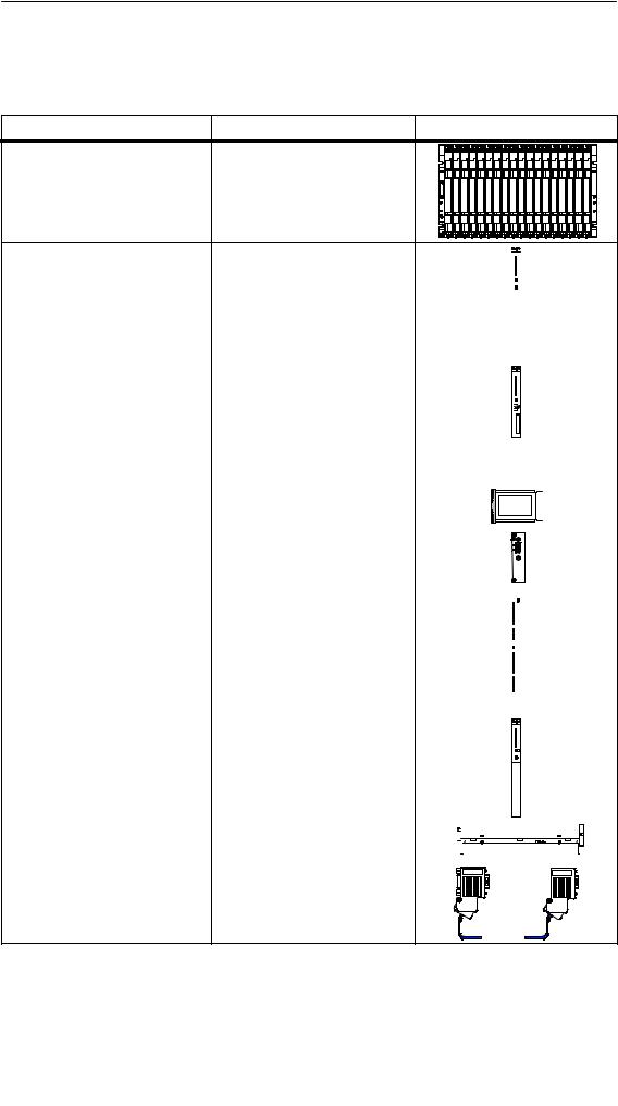
The most important components of the S7-400 and their functions are given in the following tables:
Components |
Function |
Illustration |
Racks |
... provide the mechanical and |
|
(UR: Universal Rack) |
electrical connections between |
|
(CR: Central Rack) |
the S7-400 modules. |
|
(ER: Expansion Rack) |
|
|
Power Supply Modules |
... convert the line voltage |
|
|
||||||||||||||||
|
|||||||||||||||||||
(PS = Power Supply) |
(120/230 VAC or 24 VDC) to the |
|
|
||||||||||||||||
|
5 VDC and 24 VDC operating |
|
|
||||||||||||||||
Accessories: |
voltages required to power the |
|
|
||||||||||||||||
|
|
|
|
|
|
|
|
|
|
|
|||||||||
Backup battery |
S7-400. |
|
|
||||||||||||||||
|
|
|
|
|
|
|
|
|
|
|
|
|
|
|
|
|
|
|
|
|
|
|
|
|
|
|
|
|
|
|
|
|
|
|
|
|
|
|
|
CPUs |
... execute the user program; |
|
|
|
|
|
|
|
|
|
|
|
|||||||
Central Processing Units (CPUs) |
communicate via the multipoint |
|
|
|
|
|
|
|
|
|
|
|
|||||||
|
interface (MPI) with other CPUs |
|
|
|
|
|
|
|
|
|
|
|
|||||||
|
or with a programming device |
|
|
|
|
|
|
|
|
|
|
|
|||||||
|
(PG). |
|
|
|
|
|
|
|
|
|
|
|
|||||||
|
|
|
|
|
|
|
|
|
|
|
|
|
|
|
|
|
|
|
|
|
|
|
|
|
|
|
|
|
|
|
|
|
|
|
|
|
|
|
|
Memory cards |
... store the user program and |
|
|
|
|
|
|
|
|
|
|
|
|
||||||
|
|
|
|
|
|
||||||||||||||
|
parameters. |
|
|
|
|
|
|
|
|
|
|
|
|
||||||
|
|
|
|
|
|
|
|
|
|
|
|
|
|
|
|
|
|
|
|
|
|
|
|
|
|
|
|
|
|
|
|
|
|
|
|
|
|
||
IF 964-DP interface module |
... used to connect distributed |
||||||||||||||||||
|
I/Os via PROFIBUS-DP |
||||||||||||||||||
|
|
|
|
|
|
|
|
|
|
|
|
|
|
|
|
|
|
||
Signal Modules |
... match the different process |
|
|
|
|
|
|
|
|
|
|||||||||
(SM = Signal Module) |
signal levels to the S7-400. |
|
|
|
|
|
|
|
|
|
|
||||||||
|
|
|
|
|
|
|
|
|
|
||||||||||
(digital input modules, digital |
... form the interface between |
|
|
|
|
|
|
|
|
|
|||||||||
|
|
|
|
|
|
|
|
|
|
||||||||||
output modules, analog input |
PLC and process. |
|
|
|
|
|
|
|
|
|
|
||||||||
|
|
|
|
|
|
|
|
|
|
||||||||||
modules, analog output modules) |
|
|
|
|
|
|
|
|
|
|
|
|
|
|
|
|
|
|
|
|
|
|
|
|
|
|
|
|
|
|
|
|
|
|
|
|
|
|
|
Accessories: |
|
|
|
|
|
|
|
|
|
|
|
|
|
|
|
|
|
|
|
|
|
|
|
|
|
|
|
|
|
|
|
|
|
|
|
|
|
|
|
Front connector with three |
|
|
|
|
|
|
|
|
|
|
|
|
|
|
|
|
|
|
|
|
|
|
|
|
|
|
|
|
|
|
|
|
|
|
|
|
|
|
|
different terminal systems |
|
|
|
|
|
|
|
|
|
|
|
|
|
|
|
|
|
|
|
|
|
|
|
|
|
|
|
|
|
|
|
|
|
|
|
|
|
|
|
|
|
|
|
|
|
|
|
|
|
|
|
|
|
|
|
|
|||
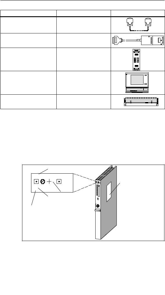
Interface modules |
... interconnect the individual |
||||||||||||||||||
(IM = Interface Module) |
racks of an S7-400. |
||||||||||||||||||
Accessories: |
|
|
|
|
|
|
|
|
|
|
|
|
|
|
|
|
|
|
|
Connecting cable |
|
|
|
|
|
|
|
|
|
|
|
|
|
|
|
|
|
|
|
Terminator |
|
|
|
|
|
|
|
|
|
|
|
|
|
|
|
|
|
|
|
|
|
|
|
|
|
|
|
|
|
|
|
|
|
|
|
|
|||
Cable ducts |
...are used for routing cables and |
|
|
|
|
|
|
|
|
|
|
|
|
|
|
|
|||
|
|
|
|
|
|
|
|
|
|
|
|
|
|
||||||
|
|
|
|
|
|
|
|
|
|
|
|
|
|
|
|
|
|
||
|
as ventilation. |
|
|
|
|
|
|
|
|
|
|
|
|
|
|
|
|
|
|
|
|
|
|
|
|
|
|
|
|
|
|
|
|
|
|
|
|
|
|
|
|
|
|
|
|
|
|
|
|
|
|
|
|
|
|
|
|
|
|
|
|
|
|
|
|
||||||||||||||
PROFIBUS bus cables |
...connect CPUs to programming |
||||||||||||||||||
|
devices. |
||||||||||||||||||
|
|
|
|
|
|
|
|
|
|
|
|
|
|
|
|
|
|
|
|
1-2 |
Automation System S7-400 |
Hardware and Installation |
|
A5E00850741-01 |
|
|
Product Overview |
Components |
Function |
Illustration |
PG cables |
...connect a CPU to a |
|
|
programming device. |
|
PROFIBUS components |
... connect the S7-400 to other |
|
for example, PROFIBUS bus |
S7-400 devices or programming |
|
terminal |
devices. |
|
RS 485 repeaters |
...amplify data signals on bus |
|
|
lines and links bus segments. |
|
Programming device (PG) or PC |
...configures, programs, debugs, |
|
with the STEP 7 software |
and assigns parameters to the |
|
package |
S7-400. |
|
Fan subassemblies |
...ventilates modules in special |
|
(for special areas of application) |
cases; can be operated with or |
|
|
without a filter. |
|
Additional components of the S7-400 such as communications processors, function modules, etc., are described in separate manuals.
Location of the order number and product version
The order number and product version are printed on every module of the SIMATIC S7-400. The firmware version is also printed on the CPUs. The following figure shows their locations on a module.
For the product version, an X is entered instead of the valid number. The following figure shows a module with Product Version 1.
Module designation
CPU 412-1
X 2 3 4
412-1XF04-0AB0 V 4.0
Type label
Product version
Abbreviated order number (6ES7 ...)
Firmware version (in CPUs)
Automation System S7-400 |
Hardware and Installation |
1-3 |
A5E00850741-01 |
|
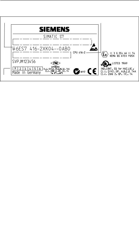
Product Overview
Example of a rating plate
Order no. |
Module designation |
Product version |
Approvals and marks |
|
1-4 |
Automation System S7-400 |
Hardware and Installation |
|
A5E00850741-01 |

Installing the S7-400 |
2 |
Chapter Overview
Section |
Description |
Page |
|
|
|
2.1 |
S7-400 Installation |
2-2 |
|
|
|
2.2 |
Installing the Central Rack (CR) and Expansion Rack (ER) |
2-6 |
|
|
|
2.3 |
Segmented CR |
2-8 |
|
|
|
2.4 |
Subdivided CR |
2-9 |
|
|
|
2.5 |
Mounting and Grounding the Racks |
2-10 |
|
|
|
2.6 |
Chassis Terminal Connection in the Non-Isolated Configuration |
2-16 |
|
|
|
2.7 |
Methods of Ventilation |
2-18 |
|
|
|
2.8 |
Changing the Ventilation with the Cable Duct and Fan Subassembly |
2-20 |
|
|
|
2.9 |
Installing the Fan Subassembly |
2-22 |
|
|
|
2.10 |
Installing the Cable Duct |
2-24 |
|
|
|
2.11 |
Choosing and Setting up Cabinets with the S7-400 |
2-25 |
|
|
|
2.12 |
Rules for the Arrangement of Modules |
2-29 |
|
|
|
2.13 |
Installing Modules in a Rack |
2-30 |
|
|
|
2.14 |
Marking the Modules with Slot Labels |
2-33 |
|
|
|
2.15 |
Methods of Expansion and Networking |
2-34 |
|
|
|
2.16 |
Accessories |
2-35 |
|
|
|
Automation System S7-400 |
Hardware and Installation |
2-1 |
A5E00850741-01 |
|
Installing the S7-400
2.1S7-400 Installation
Introduction
An S7-400 programmable controller consists of a central rack (CR) and one or more expansion racks (ERs), as required. You can add ERs to compensate for lack of slots for your application or operate signal modules at remote locations (e.g. in the immediate vicinity of your process).
When using ERs, you need interface modules (IMs) as well as the additional racks, and additional power supply modules if necessary. When using interface modules, you must always use the appropriate partners: you insert a send IM in the CR, and the matching receive IM in each connected ER (see Reference Manual,
Chapter 6).
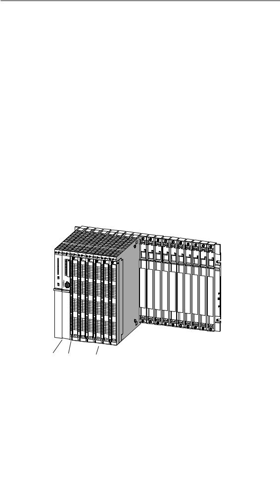
Central Rack (CR) and Expansion Rack (ER)
The rack containing the CPU is known as the central rack (CR). The racks containing modules in the system and connected to the CR are the expansion racks (ERs).
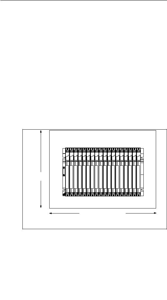
Shown in Figure 2-1 is a rack with 18 slots configured as a CR.
PS CPU |
SMs |
|
|
Figure 2-1 Rack Fitted with Modules in the S7-400 System
2-2 |
Automation System S7-400 |
Hardware and Installation |
|
A5E00850741-01 |

Installing the S7-400
Connecting the CR and ER(s)
To connect one or more ERs to a CR, you must fit one or more send IMs in the CR.
The send IMs have two interfaces. You can connect one chain of up to four ERs to each of the two interfaces of a send IM in the CR.
Different IMs are available for local connection and remote connection.
Connecting with a 5 V Supply
For a local connection with the IM 460-1 and IM 461-1, the 5 V supply voltage is also transferred via the interface modules. There must therefore be no power supply module inserted in an ER connected to an IM 460-1/IM 461-1.
Up to 5 A may flow through each of the two interfaces of an IM 460-1. This means that each ER connected via an IM 460-1/461-1 can be powered with a maximum of 5 A at 5 V. For further details, see the Reference Manual, Chapter 6.
Overview of the Connections
Observe the connection rules at the end of this section.
|
Local Connection |
Remote Connection |
|||
|
|
|
|
|
|
Send IM |
460-0 |
460-1 |
460-3 |
460-4 |
|
|
|
|
|
|
|
Receive IM |
461-0 |
461-1 |
461-3 |
461-4 |
|
|
|
|
|
|
|
Max. number of connectable |
4 |
1 |
4 |
4 |
|
EMs per chain |
|||||
|
|
|
|
||
|
|
|
|
|
|
Max. distance |
5 m |
1.5 m |
102.25 m |
605 m |
|
|
|
|
|
|
|
5 V transfer |
No |
Yes |
No |
No |
|
|
|
|
|
|
|
Max. current transfer per inter- |
-- |
5 A |
-- |
-- |
|
face |
|||||
|
|
|
|
||
|
|
|
|
|
|
Communication bus transmission |
Yes |
No |
Yes |
No |
|
|
|
|
|
|
|
Automation System S7-400 |
Hardware and Installation |
2-3 |
A5E00850741-01 |
|
Installing the S7-400
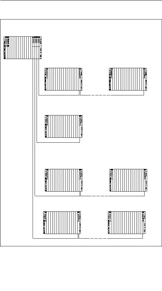
Ways of Connecting Central and Expansion Racks
|
|
|
|
|
|
|
|
IM 460-4 |
|
|
|
|
|
|
|
|
IM 460-3 |
|
|
|
|
|
|
|
|
IM 460-1 |
Central rack CR |
|
|
|
|
|
|
|
IM 460-0 |
|
|
|
|
|||||
|
|
|
|
|
|
|
|
Expansion without 5 V local transfer |
|
Expansion rack ER 1 |
Expansion rack ER 4 |
IM 461-0 |
IM 461-0 |
Chain length max. 5 m
Expansion with 5 V local transfer
Expansion rack ER 1
IM 461-1 |
|
Chain length max. 1.5 m |
|
Remote expansion |
|
Expansion rack ER 1 |
Expansion rack ER 4 |
IM 461-3 |
IM 461-3 |
|
Chain length max. 102.25 m |
Expansion rack ER 1 |
Expansion rack ER 4 |
IM 461-4 |
IM 461-4 |
Chain length max. 605 m
2-4 |
Automation System S7-400 |
Hardware and Installation |
|
A5E00850741-01 |
Installing the S7-400
Rules for Connection
When you connect a central rack to expansion racks, you must observe the following rules:
•You can connect up to 21 ERs of the S7-400 to one CR.
•The ERs are assigned numbers to identify them. The rack number must be set on the coding switch of the receive IM. Any rack number between 1 and 21 may be assigned. Numbers must not be duplicated.
•You may insert up to six send IMs in one CR. However, only two send IMs with 5 V transfer are allowed in one CR.
•Each chain connected to the interface of a send IM can comprise up to four ERs (without 5 V transfer) or one ER (with 5 V transfer).
•The exchange of data via the communication bus is limited to 7 racks, meaning the CR and ER numbers 1 to 6.
•The maximum (total) cable lengths specified for the type of connection must not be exceeded.
Type of Connection |
Maximum (Total) Cable Length |
|
|
|
|
Local connection with 5 V transfer via |
1.5 m |
|
IM 460-1 and IM 461-1 |
||
|
||
|
|
|
Local connection without 5 V transfer via |
5 m |
|
IM 460-0 and IM 461-0 |
||
|
||
|
|
|
Remote connection via IM 460-3 and |
102.25 m |
|
IM 461-3 |
||
|
||
|
|
|
Remote connection via IM 460-4 and |
605 m |
|
IM 461-4 |
||
|
||
|
|
Automation System S7-400 |
Hardware and Installation |
2-5 |
A5E00850741-01 |
|

Installing the S7-400
2.2Installing the Central Rack (CR) and Expansion Rack (ER)
Function of the Racks
The racks of the S7-400 system form the basic framework which accepts the individual modules. The modules exchange data and signals and are powered via the backplane bus. The racks are designed for wall mounting, for mounting on rails, and for installation in frames and cabinets.
Racks in the S7-400 System
Rack |
No. of |
Available |
Application |
Characteristics |
|
Slots |
Buses |
|
|
||
|
|
|
|||
|
|
|
|
|
|
UR1 |
18 |
I/O bus |
CR |
Rack for all module types in the S7-400. |
|
|
|
Communication |
or |
||
UR2 |
9 |
||||
bus |
ER |
|
|||
|
|
|
|||
|
|
|
|
|
|
|
|
|
|
Racks for signal modules (SMs), receive |
|
|
|
|
|
IMs, and all power supply modules. |
|
|
|
|
|
The I/O bus has the following restric- |
|
ER1 |
18 |
|
|
tions: |
|
|
|
• Interrupts from modules have no |
|||
|
|
|
|
||
|
|
|
|
effect because no interrupt lines |
|
|
|
|
|
exist. |
|
|
|
Restricted I/O |
ERs |
• Modules are not supplied with 24 V, |
|
|
|
bus |
i.e. modules requiring 24 V cannot |
||
|
|
|
|||
|
|
|
|
be used (see technical data of the |
|
|
|
|
|
modules). |
|
ER2 |
9 |
|
|
• Modules are neither backed up by |
|
|
|
the battery in the power supply |
|||
|
|
|
|
||
|
|
|
|
module nor by the voltage applied |
|
|
|
|
|
externally to the CPU or receive IM |
|
|
|
|
|
(EXT.BATT. socket). |
|
|
|
|
|
|
|
|
|
I/O bus, |
|
Rack for all module types in the S7-400 |
|
CR2 |
18 |
segmented |
Segmented |
except receive IMs. |
|
Communication |
CR |
The I/O bus is subdivided into 2 I/O bus |
|||
|
|
||||
|
|
bus, continuous |
|
segments of 10 and 8 slots respectively. |
|
|
|
|
|
|
|
CR3 |
4 |
I/O bus |
CR in standard |
Racks for all S7-400 module types ex- |
|
Communication |
cept receive IMs. CPUs 41x-H only in |
||||
systems |
|||||
|
|
bus |
stand-alone operation. |
||
|
|
|
|||
|
|
|
|
|
|
|
|
I/O bus, |
Subdivided CR or |
Rack for all S7-400 modules except |
|
|
|
ER for compact in- |
send IMs. |
||
|
|
segmented |
|||
UR2-H |
2*9 |
stallation of a fault-- |
The I/O bus and communication bus are |
||
Communication |
|||||
|
|
tolerant system |
divided into 2 bus segments, each with 9 |
||
|
|
bus, segmented |
|||
|
|
|
slots. |
||
|
|
|
|
||
|
|
|
|
|
2-6 |
Automation System S7-400 |
Hardware and Installation |
|
A5E00850741-01 |
Installing the S7-400
Electrical Supply
The modules inserted in the rack are supplied with the required operating voltages (5 V for logic, 24 V for interfaces) via the backplane bus and base connector, by the power supply module fitted in the slot on the extreme left in the rack.
For local connections, ERs can also be supplied with power via the IM 460-1 / IM 461-1 interface modules.
5 A may flow through each of the two interfaces of a send IM 460-1, meaning each ER in a local connection can be supplied with up to 5 A.
I/O Bus
The I/O bus is a parallel backplane bus designed for the fast interchange of I/O signals. Each rack has an I/O bus. Time-critical operations to access the process data of the signal modules take place via the I/O bus.
Communication Bus (C Bus)
The communication bus (C bus) is a serial backplane bus designed for the fast exchange of large volumes of data parallel to the I/O signals. Except for racks ER1 and ER2, each rack has a communication bus.
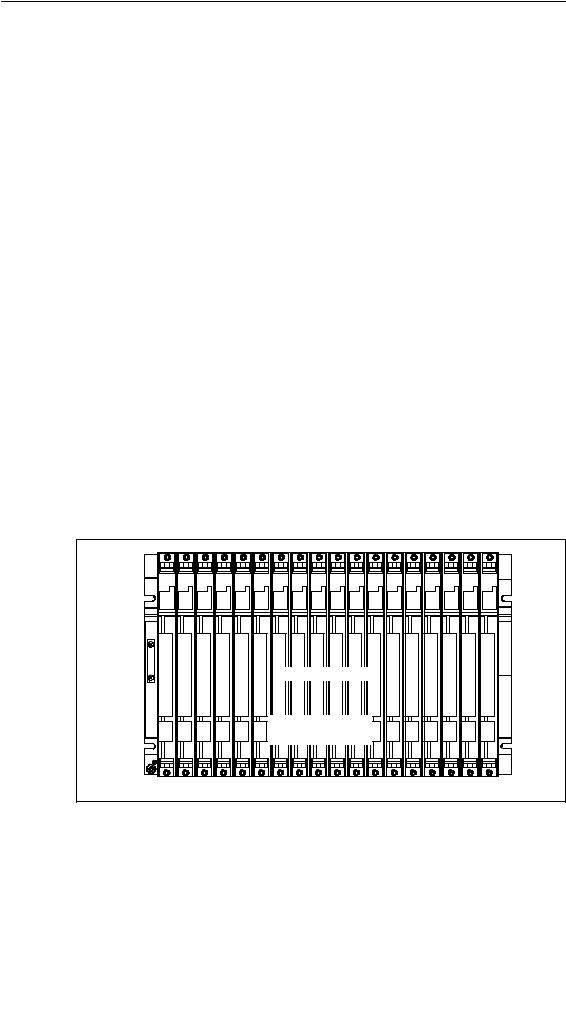
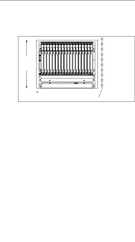
Rack with I/O Bus and Communication Bus
The following figure shows a rack with an I/O bus and a communication bus. The I/O bus connector and communication bus connector can be seen at each slot. When the rack is delivered, these connectors are protected by a cover.
1 |
2 |
3 |
4 |
5 |
6 |
7 |
8 |
9 |
10 |
11 |
12 |
13 |
14 |
15 |
16 |
17 |
18 |
I/O bus connector
Communication
bus connector
Automation System S7-400 |
Hardware and Installation |
2-7 |
A5E00850741-01 |
|
Installing the S7-400
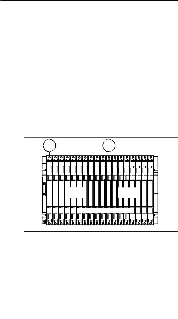
2.3Segmented CR
Properties
The “segmented” characteristic relates to the configuration of the CR. In the (non-segmented) CR the I/O bus is continuous and interconnects all 18 or 9 slots; in the segmented CR, however, the I/O bus consists of two I/O bus segments.
A segmented CR has the following important characteristics:
•The communication bus is continuous (global), whilst the I/O bus is divided into two I/O bus segments of 10 and 8 slots respectively.
•One CPU can be inserted per local bus segment.
•The two CPUs in a segmented CR may be in different operating states.
•The two CPUs can communicate with each other via the communication bus.
•All the modules inserted in a segmented CR are powered by the power supply module at slot 1.
•Both segments have a common backup battery.
The following figure shows a segmented CR with divided I/O bus and continuous communication bus.
1 |
|
|
|
|
|
|
|
|
|
11 |
|
|
|
|
|
|
|
SEG1 |
|
|
|
|
|
|
|
SEG2 |
|
|
|
|
|
|
|||
1 |
2 |
3 |
4 |
5 |
6 |
7 |
8 |
9 |
10 |
11 |
12 |
13 |
14 |
15 |
16 |
17 |
18 |
SEG1 |
SEG1 |
SEG1 |
SEG1 |
SEG1 |
SEG1 |
SEG1 |
SEG1 |
SEG1 |
SEG1 |
SEG2 |
SEG2 |
SEG2 |
SEG2 |
SEG2 |
SEG2 |
SEG2 |
SEG2 |
I/O bus Segment 1
I/O bus Segment 2
Communication bus
2-8 |
|
Automation System S7-400 |
Hardware and Installation |
|
|||
|
|
A5E00850741-01 |
Installing the S7-400
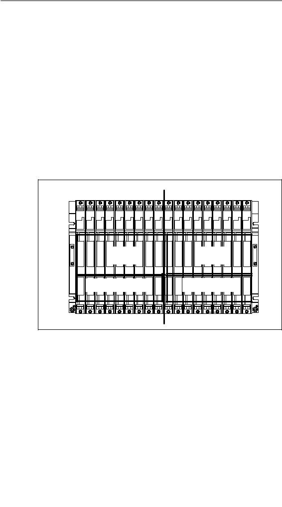
2.4Subdivided CR
Characteristics
The “subdivided” characteristic relates to the configuration of the CR. In the (non-divided) CR the I/O bus and communication bus are continuous and interconnect all the slots; in the subdivided CR, however, the I/O bus and communication bus consist of two segments each. The UR2-H rack used here functions as two electrically isolated UR2 racks on the same rack profile.
A subdivided CR has the following important characteristics:
•The communication bus and I/O bus are subdivided into two segments with 9 slots each.
•Each segment represents a self-contained CR.
The following figure shows a divided CR with a divided I/O bus and communication bus.
|
|
|
Division I |
|
|
|
|
|
|
|
Division II |
|
|
|
|||
1 |
2 |
3 |
4 |
5 |
6 |
7 |
8 |
9 |
1 |
2 |
3 |
4 |
5 |
6 |
7 |
8 |
9 |
1 |
2 |
3 |
4 |
5 |
6 |
7 |
8 |
9 |
1 |
2 |
3 |
4 |
5 |
6 |
7 |
8 |
9 |
|
|
|
|
I/O bus |
|
|
|
|
|
|
|
I/O bus |
|
|
|
||
|
|
|
Segment 1 |
|
|
|
|
|
|
|
Segment 2 |
|
|
||||
|
Communication bus |
|
|
|
|
Communication bus |
|
||||||||||
|
|
|
Segment 1 |
|
|
|
|
|
|
Segment 2 |
|
|
|
||||
|
|
|
|
|
|
|
|
|
|
|
|
|
|
|
|||
Automation System S7-400 |
Hardware and Installation |
2-9 |
A5E00850741-01 |
|
Installing the S7-400
2.5Mounting and Grounding the Racks
Important Notes on Installation
The S7-400 racks are designed for wall mounting, mounting on rails, and for installation in frames and cabinets. Their mounting dimensions are compliant with DIN 41 494.
According to the UL/CSA and the EU Directive 73/23/EEC (low-voltage directive), installation in a cabinet, a casing, or a closed operations room is necessary in order to fulfil the requirements for electrical safety (see Reference Manual, Chapter 1).
Step 1: Retaining Distances Between Devices
You must observe the minimum distances between the rack and neighboring devices. You need these minimum clearances during installation and operation.
•For fitting and removing modules
•For fitting and disconnecting the module front connectors
•To ensure the air flow required for cooling the modules during operation The following figure shows the minimum space you must provide for a rack.
|
|
|
|
|
|
40 mm |
|
|
|
|
|
|
|
|
|
|
||
|
1 |
2 |
3 |
4 |
5 |
6 |
7 |
8 |
9 |
10 |
11 |
12 |
13 |
14 |
15 |
16 |
17 |
18 |
|
20 mm |
|
|
|
|
|
|
|
|
|
|
|
|
|
|
|
|
20 mm |
352 mm |
* |
|
|
|
|
|
|
|
|
|
|
|
|
|
|
|
|
|
|
|
|
|
|
|
22 mm |
|
|
|
|
|
|
|
|
|
|
||
523 mm (18 slots)
298 mm (9 slots)
173 mm (4 slots)
*40 mm facilitates the mounting of a fan subassembly Mounting depth, fitted: max. 237 mm
2-10 |
Automation System S7-400 |
Hardware and Installation |
|
A5E00850741-01 |
Installing the S7-400
Space Required When Using Cable Channels and Fan Subassemblies
A cable duct or fan subassembly must be installed in the 19-inch pitch immediately below the rack. Additional space for cable routing must be provided on both sides.
The following figure shows how much space you need to allow for when using a cable duct or fan subassembly.
1 |
2 |
3 |
4 |
5 |
6 |
7 |
8 |
9 |
10 |
11 |
12 |
13 |
14 |
15 |
16 |
17 |
18 |
440 mm |
|
|
|
|
|
|
|
|
|
|
|
|
|
|
|
|
|
|
|
|
Cable duct/fan subassembly |
|
|
||||||||||||
 523 mm (with cable duct)
  543 mm (with fan subassembly)
Mounting depth, fitted: max. 237 mm 19-inch reference level
Dimensions of the Racks
The following figure shows the dimensions for racks with 18, 9 and 4 slots and the positions of cutouts for screw mounting.
The cutouts are arranged according to the 19-inch standard.
Automation System S7-400 |
Hardware and Installation |
2-11 |
A5E00850741-01 |
|

Installing the S7-400
60 mm |
1 2 3 4 5 6 7 8 9 10 11 12 13 14 15 16 17 18 |
290 mm 190 mm
40 mm 
465 mm
483 mm
1 |
2 |
3 |
4 |
1 |
2 |
3 |
4 |
5 |
6 |
7 |
8 |
9 |
1 2 3 4
290 mm 190 mm
Depth = 28 mm without modules
Depth = 237 mm with modules
40 mm
115 mm |
240 mm |
|
133 mm
258 mm
Step 2: Mounting the Rack
Screw the rack onto the mounting panel.
When mounting the equipment on a metal mounting plate, make sure to establish a low-impedance connection. On varnished or anodized metals, for example, wlayws use a suitable contact agent or special contact washers.
Special measures need not be taken if you do not use this type of panel.
2-12 |
Automation System S7-400 |
Hardware and Installation |
|
A5E00850741-01 |
Installing the S7-400
Mounting Screws
You have a choice of the following types of screw for securing a rack:
Screw Type |
Explanation |
|
|
|
|
M6 cylinder-head screw to |
Choose the screw length according to your |
|
ISO 1207/ISO 1580 (DIN 84/DIN 85) |
assembly. |
|
|
You also need “6.4” washers to ISO 7092 |
|
M6 hex. screw to ISO 4017 (DIN 4017) |
||
(DIN 433). |
||
|
||
|
|
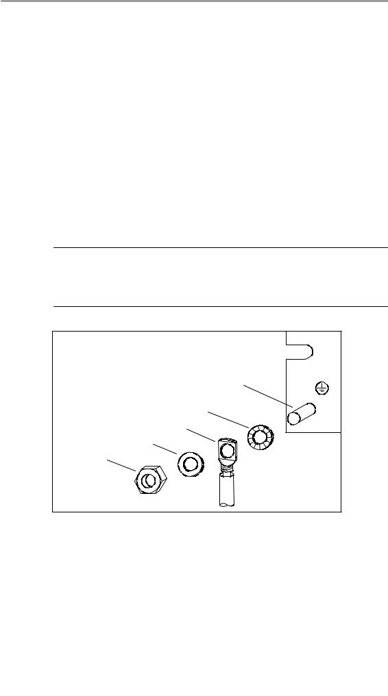
Step 3: Connecting the Rack to the Chassis Ground
Connect the rack to the chassis ground. A threaded bolt is provided for this purpose on the bottom left of the rack.
Minimum cross-section of the conductor to the chassis ground: 10 mm2.
If the S7-400 is mounted on a mobile rack, you must provide a flexible conductor to the chassis ground.
Note
Always ensure that there is a low-impedance connection to the chassis ground (see the figure below). You achieve this with the shortest possible, low-resistance conductor with a large surface to establish large-area contact.
M6 threaded bolt |
Contact washer |
Terminal |
Plain washer |
M6 nut |
To chassis ground |
Automation System S7-400 |
Hardware and Installation |
2-13 |
A5E00850741-01 |
|
Installing the S7-400
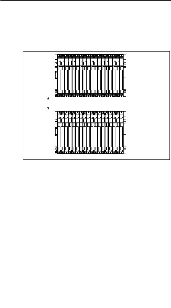
Step 4: Mounting Additional Racks
For S7-400 assemblies containing two or more racks, make allowances for additional clearance between the racks for installing a fan subassembly or cable duct.
The figure below shows the clearance you must allow between two racks of the S7-400 during installation.
1 |
2 |
3 |
4 |
5 |
6 |
7 |
8 |
9 |
10 |
11 |
12 |
13 |
14 |
15 |
16 |
17 |
18 |
110 mm
1 |
2 |
3 |
4 |
5 |
6 |
7 |
8 |
9 |
10 |
11 |
12 |
13 |
14 |
15 |
16 |
17 |
18 |
2-14 |
Automation System S7-400 |
Hardware and Installation |
|
A5E00850741-01 |
Loading...